EP4477883A1 - Ölfreier luftkompressor - Google Patents
Ölfreier luftkompressor Download PDFInfo
- Publication number
- EP4477883A1 EP4477883A1 EP22926095.5A EP22926095A EP4477883A1 EP 4477883 A1 EP4477883 A1 EP 4477883A1 EP 22926095 A EP22926095 A EP 22926095A EP 4477883 A1 EP4477883 A1 EP 4477883A1
- Authority
- EP
- European Patent Office
- Prior art keywords
- oil
- compressor body
- compressor
- air
- pressure stage
- Prior art date
- Legal status (The legal status is an assumption and is not a legal conclusion. Google has not performed a legal analysis and makes no representation as to the accuracy of the status listed.)
- Pending
Links
Images


Classifications
-
- F—MECHANICAL ENGINEERING; LIGHTING; HEATING; WEAPONS; BLASTING
- F04—POSITIVE - DISPLACEMENT MACHINES FOR LIQUIDS; PUMPS FOR LIQUIDS OR ELASTIC FLUIDS
- F04C—ROTARY-PISTON, OR OSCILLATING-PISTON, POSITIVE-DISPLACEMENT MACHINES FOR LIQUIDS; ROTARY-PISTON, OR OSCILLATING-PISTON, POSITIVE-DISPLACEMENT PUMPS
- F04C18/00—Rotary-piston pumps specially adapted for elastic fluids
- F04C18/08—Rotary-piston pumps specially adapted for elastic fluids of intermeshing-engagement type, i.e. with engagement of co-operating members similar to that of toothed gearing
- F04C18/12—Rotary-piston pumps specially adapted for elastic fluids of intermeshing-engagement type, i.e. with engagement of co-operating members similar to that of toothed gearing of other than internal-axis type
- F04C18/14—Rotary-piston pumps specially adapted for elastic fluids of intermeshing-engagement type, i.e. with engagement of co-operating members similar to that of toothed gearing of other than internal-axis type with toothed rotary pistons
- F04C18/16—Rotary-piston pumps specially adapted for elastic fluids of intermeshing-engagement type, i.e. with engagement of co-operating members similar to that of toothed gearing of other than internal-axis type with toothed rotary pistons with helical teeth, e.g. chevron-shaped, screw type
-
- F—MECHANICAL ENGINEERING; LIGHTING; HEATING; WEAPONS; BLASTING
- F04—POSITIVE - DISPLACEMENT MACHINES FOR LIQUIDS; PUMPS FOR LIQUIDS OR ELASTIC FLUIDS
- F04C—ROTARY-PISTON, OR OSCILLATING-PISTON, POSITIVE-DISPLACEMENT MACHINES FOR LIQUIDS; ROTARY-PISTON, OR OSCILLATING-PISTON, POSITIVE-DISPLACEMENT PUMPS
- F04C29/00—Component parts, details or accessories of pumps or pumping installations, not provided for in groups F04C18/00 - F04C28/00
- F04C29/02—Lubrication; Lubricant separation
- F04C29/025—Lubrication; Lubricant separation using a lubricant pump
-
- F—MECHANICAL ENGINEERING; LIGHTING; HEATING; WEAPONS; BLASTING
- F04—POSITIVE - DISPLACEMENT MACHINES FOR LIQUIDS; PUMPS FOR LIQUIDS OR ELASTIC FLUIDS
- F04C—ROTARY-PISTON, OR OSCILLATING-PISTON, POSITIVE-DISPLACEMENT MACHINES FOR LIQUIDS; ROTARY-PISTON, OR OSCILLATING-PISTON, POSITIVE-DISPLACEMENT PUMPS
- F04C18/00—Rotary-piston pumps specially adapted for elastic fluids
- F04C18/08—Rotary-piston pumps specially adapted for elastic fluids of intermeshing-engagement type, i.e. with engagement of co-operating members similar to that of toothed gearing
- F04C18/10—Rotary-piston pumps specially adapted for elastic fluids of intermeshing-engagement type, i.e. with engagement of co-operating members similar to that of toothed gearing of internal-axis type with the outer member having more teeth or tooth equivalents, e.g. rollers, than the inner member
-
- F—MECHANICAL ENGINEERING; LIGHTING; HEATING; WEAPONS; BLASTING
- F04—POSITIVE - DISPLACEMENT MACHINES FOR LIQUIDS; PUMPS FOR LIQUIDS OR ELASTIC FLUIDS
- F04C—ROTARY-PISTON, OR OSCILLATING-PISTON, POSITIVE-DISPLACEMENT MACHINES FOR LIQUIDS; ROTARY-PISTON, OR OSCILLATING-PISTON, POSITIVE-DISPLACEMENT PUMPS
- F04C28/00—Control of, monitoring of, or safety arrangements for, pumps or pumping installations specially adapted for elastic fluids
- F04C28/06—Control of, monitoring of, or safety arrangements for, pumps or pumping installations specially adapted for elastic fluids specially adapted for stopping, starting, idling or no-load operation
-
- F—MECHANICAL ENGINEERING; LIGHTING; HEATING; WEAPONS; BLASTING
- F04—POSITIVE - DISPLACEMENT MACHINES FOR LIQUIDS; PUMPS FOR LIQUIDS OR ELASTIC FLUIDS
- F04C—ROTARY-PISTON, OR OSCILLATING-PISTON, POSITIVE-DISPLACEMENT MACHINES FOR LIQUIDS; ROTARY-PISTON, OR OSCILLATING-PISTON, POSITIVE-DISPLACEMENT PUMPS
- F04C29/00—Component parts, details or accessories of pumps or pumping installations, not provided for in groups F04C18/00 - F04C28/00
- F04C29/0042—Driving elements, brakes, couplings, transmissions specially adapted for pumps
- F04C29/005—Means for transmitting movement from the prime mover to driven parts of the pump, e.g. clutches, couplings, transmissions
-
- F—MECHANICAL ENGINEERING; LIGHTING; HEATING; WEAPONS; BLASTING
- F04—POSITIVE - DISPLACEMENT MACHINES FOR LIQUIDS; PUMPS FOR LIQUIDS OR ELASTIC FLUIDS
- F04C—ROTARY-PISTON, OR OSCILLATING-PISTON, POSITIVE-DISPLACEMENT MACHINES FOR LIQUIDS; ROTARY-PISTON, OR OSCILLATING-PISTON, POSITIVE-DISPLACEMENT PUMPS
- F04C29/00—Component parts, details or accessories of pumps or pumping installations, not provided for in groups F04C18/00 - F04C28/00
- F04C29/0092—Removing solid or liquid contaminants from the gas under pumping, e.g. by filtering or deposition; Purging; Scrubbing; Cleaning
-
- F—MECHANICAL ENGINEERING; LIGHTING; HEATING; WEAPONS; BLASTING
- F04—POSITIVE - DISPLACEMENT MACHINES FOR LIQUIDS; PUMPS FOR LIQUIDS OR ELASTIC FLUIDS
- F04C—ROTARY-PISTON, OR OSCILLATING-PISTON, POSITIVE-DISPLACEMENT MACHINES FOR LIQUIDS; ROTARY-PISTON, OR OSCILLATING-PISTON, POSITIVE-DISPLACEMENT PUMPS
- F04C29/00—Component parts, details or accessories of pumps or pumping installations, not provided for in groups F04C18/00 - F04C28/00
- F04C29/04—Heating; Cooling; Heat insulation
-
- F—MECHANICAL ENGINEERING; LIGHTING; HEATING; WEAPONS; BLASTING
- F04—POSITIVE - DISPLACEMENT MACHINES FOR LIQUIDS; PUMPS FOR LIQUIDS OR ELASTIC FLUIDS
- F04C—ROTARY-PISTON, OR OSCILLATING-PISTON, POSITIVE-DISPLACEMENT MACHINES FOR LIQUIDS; ROTARY-PISTON, OR OSCILLATING-PISTON, POSITIVE-DISPLACEMENT PUMPS
- F04C29/00—Component parts, details or accessories of pumps or pumping installations, not provided for in groups F04C18/00 - F04C28/00
- F04C29/12—Arrangements for admission or discharge of the working fluid, e.g. constructional features of the inlet or outlet
-
- F—MECHANICAL ENGINEERING; LIGHTING; HEATING; WEAPONS; BLASTING
- F04—POSITIVE - DISPLACEMENT MACHINES FOR LIQUIDS; PUMPS FOR LIQUIDS OR ELASTIC FLUIDS
- F04C—ROTARY-PISTON, OR OSCILLATING-PISTON, POSITIVE-DISPLACEMENT MACHINES FOR LIQUIDS; ROTARY-PISTON, OR OSCILLATING-PISTON, POSITIVE-DISPLACEMENT PUMPS
- F04C2210/00—Fluid
- F04C2210/22—Fluid gaseous, i.e. compressible
- F04C2210/221—Air
-
- F—MECHANICAL ENGINEERING; LIGHTING; HEATING; WEAPONS; BLASTING
- F04—POSITIVE - DISPLACEMENT MACHINES FOR LIQUIDS; PUMPS FOR LIQUIDS OR ELASTIC FLUIDS
- F04C—ROTARY-PISTON, OR OSCILLATING-PISTON, POSITIVE-DISPLACEMENT MACHINES FOR LIQUIDS; ROTARY-PISTON, OR OSCILLATING-PISTON, POSITIVE-DISPLACEMENT PUMPS
- F04C2270/00—Control; Monitoring or safety arrangements
- F04C2270/70—Safety, emergency conditions or requirements
- F04C2270/72—Safety, emergency conditions or requirements preventing reverse rotation
Definitions
- the present invention relates to an oil-free air compressor such as an oil-free screw compressor.
- An oil-free screw compressor does not use lubricating oil or has a structure in which the lubricating oil does not enter a compression chamber, and provides clean compressed air that does not contain oil, and rotors rotate without being in contact with each other, so that the oil-free screw compressor has the advantage of having good durability and requiring little maintenance.
- Patent Document 1 discloses a "rust prevention method for a compressor during shutdown in which when the compressor is in shutdown, dry gas containing no moisture or only a small amount of moisture is suctioned into the compressor, gas containing moisture remaining in the compressor is replaced with the dry gas, and the dry gas is sealed therein" as a “rust prevention method for a compressor during shutdown” (refer to claim 1).
- Patent Document 1 JP H5-141350 A
- Patent Document 1 discloses a technique in which dry gas is suctioned into the compressor during shutdown, gas containing moisture remaining in the compressor is replaced with the dry gas, and the dry gas is sealed therein, as the rust prevention method for a compressor during shutdown.
- an internal gap is maintained at several tens of ⁇ m to prevent leakage of the air during compression.
- air has to pass through the very small gap to flow from an intake port to a discharge port of the compressor body. For that reason, even when the dry gas is supplied to a suction side, it is difficult for the dry gas to flow to a discharge side, and this approach is not suitable for the purpose of replacing the moist air with the dry gas.
- An object of the present invention is to provide an oil-free air compressor that prevents oil from entering a compressor body by preventing a reverse rotation of the compressor body when the compressor is in shutdown, while improving the rust prevention effect, and that has improved reliability.
- an "oil-free air compressor” of the present invention is an oil-free air compressor including: an oil-free compressor body that compresses air, and that outputs the compressed air; a cooler that is connected to the compressor body, and that cools the compressed high-temperature air; a dry air supply mechanism for supplying dry air to an output side of the compressor body; and a mechanism for preventing a reverse rotation of the compressor body during a shutdown of the compressor.
- an oil-free screw compressor that is one example of an oil-free air compressor will be described.
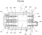
- Figs. 8A and 8B show cross-sectional views of a compressor body 1 of an oil-free screw compressor.
- Fig. 8A is a cross-sectional plan view
- Fig. 8B is a cross-sectional front view.
- the compressor body 1 is a capacity control air compressor that generates compressed air by allowing teeth of a pair of screw rotors, namely, a male rotor 50A and a female rotor 50B to mesh with each other in a state where a predetermined gap therebetween is maintained and allowing the screw rotors to rotate at high speed.
- the male rotor 50A is integrated with or directly coupled to a rotor shaft 48A
- the female rotor 50B is integrated with or directly coupled to a rotor shaft 48B.
- bearings 11A and 11B and bearings 12A and 12B are disposed in the direction of an air suction-side end portion and the direction of a discharge-side end portion, respectively, and rotatably support the rotor shafts.
- timing gears 9A and 9B are disposed at end portions of the rotor shafts 48A and 48B, respectively, the end portions being located further outside than the bearings 12A and 12B, and as the male rotor 50A connected to the rotor shaft 48A rotates, the male and female rotors rotate relative to each other due to meshing between the timing gears 9A and 9B.
- air suctioned from an intake port 41 is compressed in a working chamber 60, and then is supplied to a user side from a discharge port 42 through a predetermined compressed air path.
- a shaft seal portion 17 (17A and 17B) and a shaft seal portion 18 (18A and 18B) are disposed between the male and female rotors 50A and 50B and the bearings 11A and 11B.
- the shaft seal portion 18 is an air seal, and is an annular member that reduces leakage of the air compressed in the working chamber 60 to a bearing 11A side and the like.
- the shaft seal portion 18 is in non-contact with the rotor shaft 48A and the like, and a gap therebetween is very small, approximately several tens of ⁇ m.
- the air seals 18A (male side) and 18B (female side) are disposed on the rotor shafts 48 of the male and female rotors 50A and 50B, respectively.
- the shaft seal portion 17 is a screw seal, and serves to prevent lubricating oil from entering the working chamber 60, the lubricating oil being supplied to the bearings 11A and 11B via a path 34.
- Spiral angle grooves are applied to inner surfaces of the screw seals 17A and 17B, and the screw seals 17A and 17B are assembled in non-contact with the rotor shaft 48A and the like so as to maintain a very small gap therebetween.
- the rotation of the rotor shaft 48A and the like generates seal pressure in the groove portions of inner-diameter portions, so that the screw seals 17A and 17B act to push the lubricating oil back to the sides of the bearings 11A and 11B.
- an oil drain port 45 that collects the lubricating oil which has lubricated the bearings 11A and 11B and returns the lubricating oil to an oil reservoir 47 of a gear casing 2 is formed between the screw seals 17A and 17B and the bearings 11A and 11B.
- a shaft seal portion 20 air seal
- a shaft seal portion 19 screw seal
- the shaft seal portion 19 and the shaft seal portion 20 are disposed between the rotors 50A and 50B and the bearings 12A and 12B.
- a hole portion 44 communicating with the outside air and functioning as a gas vent for compressed air leaking from the working chamber 60 is formed between the shaft seal portion 19 and the shaft seal portion 20 of the compressor body casing.
- Three bearings 12A and three bearings 12B are disposed on each of the male and female rotor shafts. Furthermore, in the compressor body casing, a path 33 for supplying the lubricating oil from above is formed at a position between these three bearings 12. In addition, a discharge port 46 that collects the lubricating oil from a position between the bearings 12A and 12B and the screw seals 19A and 19B is formed in the compressor body casing. The lubricating oil supplied from the path 33 lubricates the bearings 12A and 12B, and then is collected from the oil drain port 46.
- the shaft seal portion 17 acts to push the lubricating oil back to the sides of the bearings 11A and 11B; however, when the compressor body rotates in a reverse direction, the shaft seal portion 17 acts to draw the lubricating oil from the bearings in the direction of the working chamber, so that it is not preferable that compressor body rotates in the reverse direction.
- the oil is prevented from entering the compressor body by preventing reverse rotation of the compressor body when the compressor is in shutdown, while improving the rust prevention effect, and reliability is improved.
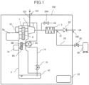
- Fig. 1 shows an oil-free screw compressor according to a first embodiment of the present invention.
- Fig. 1 shows a case where the minimum necessary devices are installed, and other devices may be installed.
- a compressor 100 includes a compressor body 1, a gear casing 2, a motor 3a as a drive source for the compressor body 1, and a motor 3c as a drive source for an oil pump 24.
- a speed-increasing drive gear 6 is attached to an output shaft of the motor 3a disposed on a side surface of the gear casing 2.
- the speed-increasing drive gear 6 meshes with a speed-increasing driven gear 7 set to a predetermined gear ratio, and transmits a driving force to a male rotor of the compressor body 1 via a rotor shaft connected to the speed-increasing driven gear 7.
- the oil pump 24 is attached to a side surface of the gear casing 2 through flange fitting, and a driving force is transmitted to the oil pump 24 via an oil pump drive gear 8A being attached to the motor 3c and an oil pump driven gear 8B that meshes with the oil pump drive gear 8A at a predetermined gear ratio.
- the oil pump 24 is a pump that circulates lubricating oil to various drive units of the compressor 100, and pressure-feeds the lubricating oil to various oil paths using the driving force transmitted via an oil pump shaft, the various oil paths being disposed in the compressor 100.
- the oil pump 24 suctions the lubricating oil from an oil reservoir 47 via an opening-closing valve 15, the oil reservoir 47 being provided at a lower portion of the gear casing 2, and pressure-feeds the lubricating oil to an oil cooler (not shown) via a path 14.
- the oil cooler is an air-cooled or water-cooled heat exchanger using a fan (not shown), and cools the lubricating oil to a predetermined temperature or less.
- Air compressed to be high temperature by the compressor body 1 becomes moist air when cooled in an aftercooler 5. For that reason, replacing the moist air with dry air is effective in preventing rust.
- a dry air supply line 23 including a dry air supply port 21 and a supply valve 22 is provided on a downstream side of the aftercooler 5, and dry air stored in an air tank 28 is supplied to the dry air supply line 23.
- the supply valve 22 is caused to perform an opening and closing operation at a predetermined timing by a control panel 32.
- a brake device 70 that operates when the compressor is in shutdown is provided for the compressor body 1.
- the brake device 70 is connected to the male rotor of the compressor body 1, and is controlled by the control panel 32 to prevent the male rotor from rotating during the supply of the dry air.
- the compressor body 1 can be prevented from rotating in the reverse direction during the supply of the dry air.
- the operation of the compressor is as follows.
- the brake device is one example of a mechanism for preventing reverse rotation of the compressor body. Any mechanism may be used as long as the mechanism can prevent reverse rotation of the compressor body, and as another example, a ratchet mechanism or the like may be used.
- the rust prevention effect is improved by supplying high-pressure dry air to the pipe on the output side of the aftercooler when the compressor is in shutdown, and the brake device that operates when the compressor is in shutdown is provided for the compressor body, so that reverse rotation of the compressor body can be prevented. And, it is possible to provide the oil-free air compressor that prevents the oil from entering the compressor body and that has improved reliability.
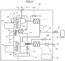
- Fig. 2 shows an oil-free screw compressor according to a second embodiment of the present invention.
- Fig. 2 shows a case where the minimum necessary devices are installed, and other devices may be installed.
- the compressor 100 includes a low-pressure stage compressor body la, a high-pressure stage compressor body 1b, the gear casing 2, and the motors 3a and 3b as drive sources.
- the low-pressure stage compressor body 1a and the high-pressure stage compressor body 1b are attached to the vicinity of an upper portion of the side surface of the gear casing 2 through flange fitting.
- Speed-increasing drive gears 6A and 6B are attached to the output shafts of the motors 3a and 3b disposed on the side surface of the gear casing 2.
- the speed-increasing drive gears 6A and 6B mesh with speed-increasing driven gears 7A and 7B set to a predetermined gear ratio, and transmit driving forces to a male rotor of the low-pressure stage compressor body 1a and a male rotor of the high-pressure stage compressor body 1b via rotor shafts connected to the speed-increasing driven gears 7A and 7B.
- An intercooler 4 is provided on a discharge side of the low-pressure stage compressor body 1a, and cools air that is compressed to be high temperature.
- An intermediate-stage pipe 13 connecting the intercooler 4 and the high-pressure stage compressor body 1b is provided, and supplies the compressed air cooled by the intercooler 4 to the high-pressure stage compressor body 1b.
- the aftercooler 5 is provided on a discharge side of the high-pressure stage compressor body lb, cools the air that is compressed to be high temperature, and outputs the air via the check valve 25.
- the intermediate-stage pipe 13 between the intercooler 4 and the high-pressure stage compressor body 1b is provided with the dry air supply line 23 including the dry air supply port 21 and the supply valve 22, and the dry air stored in the air tank 28 is supplied to the dry air supply line 23.
- the supply valve 22 is caused to perform an opening and closing operation at a predetermined timing by the control panel 32.
- the brake device 70 that operates when the compressor is in shutdown is provided for the low-pressure stage compressor body 1a.
- the brake device 70 is connected to the male rotor of the low-pressure stage compressor body la, and is controlled by the control panel 32 to prevent the rotor from rotating during the supply of the dry air.
- the low-pressure stage compressor body can be prevented from rotating in the reverse direction during the supply of the dry air.
- the operation of the compressor is as follows.
- the motors 3a and 3b are stopped and the low-pressure stage compressor body 1a and the high-pressure stage compressor body 1b are stopped.
- the air release valve 26A connected between the low-pressure stage compressor body 1a and the intercooler 4 and an air release valve 26B connected between the high-pressure stage compressor body 1b and the aftercooler 5 are opened to release pressure inside the compressor.
- the dry air stored in the air tank 28 is supplied to the intermediate-stage pipe 13 from the dry air supply line 23 including the dry air supply port 21 and the supply valve 22.
- the dry air supplied from the supply port 21 to the intermediate-stage pipe 13 is released into the atmosphere from the air release valves 26A and the air release valve 26B; however, since pressure in the intermediate-stage pipe 13 increases due to the dry air supplied from the supply port 21, a force acts to rotate the low-pressure stage compressor body 1a in the reverse direction. At this time, since braking is applied to the low-pressure stage compressor body 1a by the brake mechanism 70, the low-pressure stage compressor body 1a is prevented from rotating in the reverse direction even when high-pressure dry air is supplied.
- the brake device that operates when the compressor is in shutdown is provided for the low-pressure stage compressor, so that reverse rotation of the compressor bodies can be prevented. And, it is possible to provide a multi-stage oil-free air compressor that prevents the oil from entering the compressor bodies and that has improved reliability.
- Fig. 3 shows an oil-free screw compressor according to a third embodiment of the present invention.
- the motor is provided for each of the low-pressure stage compressor body, the high-pressure stage compressor body, and the oil pump that supplies the lubricating oil; however, in the third embodiment, these components are driven by one motor.
- the compressor 100 includes the low-pressure stage compressor body la, the high-pressure stage compressor body lb, the gear casing 2, and one motor 3 as a drive source.
- the speed-increasing drive gear 6 and the oil pump drive gear 8A are attached to an output shaft of the motor 3 disposed on the side surface of the gear casing 2.
- the speed-increasing drive gear 6 meshes with the speed-increasing driven gears 7A and 7B set to a predetermined gear ratio, and transmits driving forces to the male rotor of the low-pressure stage compressor body 1a via the rotor shaft connected to the speed-increasing driven gear 7A, and to the male rotor of the high-pressure stage compressor body 1b via the rotor shaft connected to the speed-increasing driven gear 7B.
- the pump drive gear 8A meshes with the oil pump driven gear 8B set to a predetermined gear ratio.
- the pump driven gear 8B is connected to the oil pump shaft penetrating to the outside of the gear casing 2, and transmits a driving force to the oil pump 24.
- the opening-closing valve 15 is provided on a suction side of the oil pump 24, namely, between the oil reservoir 47 and the oil pump 24.
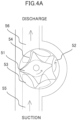
- Figs. 4A and 4B show a trochoid pump used as the oil pump, Fig. 4A shows a state of the trochoid pump when in operation, and Fig. 4B shows a state of the trochoid pump when closed.
- a working chamber formed by an inner rotor 51 and an outer rotor 52 pressure-feeds the lubricating oil from a suction flow path 55 to a discharge flow path 56 by expanding and contracting from a suction port 53 to a discharge port 54.
- the working chamber expands and contracts from the discharge port 54 to the suction port 53, so that the lubricating oil flows back to the suction port 53 from the discharge port 54.
- the suction flow path 55 is closed, the lubricating oil cannot be fed to the suction side, and a working space cannot contract, so that the pump is locked.
- the suction side 55 of the oil pump 24 is filled with the lubricating oil, so that reverse rotation of the oil pump 24 can be prevented. Since the oil pump 24 and the compressor bodies 1a and 1b are connected to each other via the drive gear 6, the compressor bodies 1a and 1b are not rotatable either if the oil pump 24 is not rotatable. Therefore, reverse rotation of the compressor bodies during stop of the compressor can be prevented.
- the trochoid pump has been provided as one example; however, any gear pump can be used as long as the gear pump transfers a fluid through meshing between teeth of gears.
- the low-pressure stage compressor body, the high-pressure stage compressor body, and the oil pump are driven by one motor via gears, and the opening-closing valve that opens during operation of the compressor and that closes during shutdown is provided on the suction side of the oil pump, so that reverse rotation of the compressor bodies when the compressor is in shutdown can be prevented. And, it is possible to provide the oil-free air compressor that prevents the oil from entering the compressor bodies and that has improved reliability.
- Fig. 5 shows an oil-free screw compressor according to a fourth embodiment of the present invention.
- the third embodiment is a multi-stage compressor including the low-pressure stage compressor body 1a and the high-pressure stage compressor body 1b; however, the present embodiment is a single-stage compressor including one compressor body.
- the compressor 100 includes the compressor body 1, the gear casing 2, and one motor 3 as a drive source.
- the speed-increasing drive gear 6 and the oil pump drive gear 8A are attached to the output shaft of the motor 3 disposed on the side surface of the gear casing 2.
- the speed-increasing drive gear 6 meshes with the speed-increasing driven gear 7 set to a predetermined gear ratio, and transmits a driving force to the male rotor of the compressor body 1 via the rotor shaft connected to the speed-increasing driven gear 7.
- the pump drive gear 8A meshes with the oil pump driven gear 8B set to a predetermined gear ratio.
- the pump driven gear 8B is connected to the oil pump shaft penetrating to the outside of the gear casing 2, and transmits a driving force to the oil pump 24.
- the opening-closing valve 15 is provided on the suction side of the oil pump 24, namely, in the oil pump suction path 14 between the oil reservoir 47 and the oil pump 24.
- the air compressed to be high temperature by the compressor body 1 becomes moist air when cooled in the aftercooler 5. For that reason, replacing the moist air with dry air is effective in preventing rust.
- the supply line 23 including the dry air supply port 21 and the supply valve 22 is provided on the downstream side of the aftercooler 5, and dry air stored in the air tank 28 is supplied to the supply line 23.
- the supply valve 22 is caused to perform an opening and closing operation at a predetermined timing by the control panel 32.
- the compressor body and the oil pump are driven by one motor via gears, and the opening-closing valve that opens during operation of the compressor and that closes during shutdown is provided on the suction side of the oil pump, so that reverse rotation of the compressor body when the compressor is in shutdown can be prevented. And, it is possible to provide the oil-free air compressor that prevents the oil from entering the compressor bodies and that has improved reliability.
- Fig. 6 shows an oil-free screw compressor according to a fifth embodiment of the present invention.
- a dry air supply port is also provided on a suction side of a low-pressure stage compressor.
- the suction pipe 103 is provided with a dry air supply line 23A including a dry air supply port 21A, the supply valve 22, and an orifice 33A.
- a dry air supply line 23B including a dry air supply port 21B, the supply valve 22, and an orifice 33B is provided in the intermediate stage.
- the air release valve 26A connected between the low-pressure stage compressor body 1a and the inner cooler 4, and the air release valve 26B connected between the high-pressure stage compressor body 1b and the aftercooler 5 are opened to release pressure inside the compressor.
- the supply valve 22 to open through the control panel 32 the dry air stored in the air tank 28 is caused to pass through the dry air supply lines 23A and 23B, and is supplied into the compressor.
- the dry air supplied from the supply port 21B to the intermediate-stage pipe 13 is released into the atmosphere from the air release valve 26A and the air release valve 26B.
- the dry air supplied from the supply port 21A is released into the atmosphere from the suction port 101.
- the multi-stage compressor has been described as an example; however, the present embodiment can also be used for the single-stage compressor shown in Fig. 1 .
- the dry air supply port 21 of the dry air supply line 23 may be connected to an outlet side of the aftercooler 5 to supply the dry air, the aftercooler 5 being provided on the discharge side of the compressor body 1, and the dry air supply port may be connected to the suction pipe 103, which is the suction side of the compressor body 1, to supply the dry air.
- the dry air when the compressor is in shutdown, the dry air is supplied to the intercooler or the aftercooler provided on the discharge side of the compressor body, and the dry air is also supplied to the suction side of the compressor body, so that reverse rotation of the compressor body can be prevented. And, it is possible to provide the oil-free air compressor that prevents the oil from entering the compressor body and that has improved reliability.
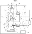
- Fig. 7 shows an oil-free screw compressor according to a sixth embodiment of the present invention.
- an unloader 105 is provided between the air suction port 101 and the suction pipe 103 in the low-pressure stage and the dry air supply port 21A is provided between the unloader 105 and the low-pressure stage compressor body 1a.
- the other configurations are the same as those of the fifth embodiment.
- the unloader 105 is a device that includes a valve thereinside, the valve throttling a path of compressed air, and that reduces power during unload operation of the compressor by controlling the valve to open during load operation and to close during unload operation. Since the compressor is normally stopped when unloading is stopped, the unloader is closed during shutdown.
- the dry air supplied from the dry air supply port 21A during shutdown of the compressor remains between the unloader 105 and the compressor body 1a, so that pressure in the suction pipe 103 increases.
- an air suction port 101 side of the suction pipe 103 is open to the atmosphere, and in order to increase the pressure in the suction pipe 103, the flow rate of the dry air supplied from the dry air supply port 21A should be set to be larger than that of the dry air supplied from the dry air supply port 21B; however, in the present embodiment, the amount of the dry air supplied from the dry air supply port 21A can be set to be smaller.
- the unloader is provided between the air suction port and the suction pipe in the low-pressure stage, and the dry air supply port is provided between the unloader and the low-pressure stage compressor body, in addition to the effects of the fifth embodiment, the amount of the dry air supplied from the dry air supply port to the suction side of the low-pressure stage compressor body can be reduced.
- the present invention is not limited to each embodiment described above, and includes various modification examples.
- the above-described embodiments have been described in detail to facilitate understanding of the present invention, and are not necessarily limited to including all the described configurations.
- a part of the configuration of one embodiment can be replaced with the configuration of another embodiment, and the configuration of another embodiment can also be added to the configuration of one embodiment.
Landscapes
- Engineering & Computer Science (AREA)
- Mechanical Engineering (AREA)
- General Engineering & Computer Science (AREA)
- Applications Or Details Of Rotary Compressors (AREA)
- Control Of Positive-Displacement Pumps (AREA)
- Compressor (AREA)
Applications Claiming Priority (2)
| Application Number | Priority Date | Filing Date | Title |
|---|---|---|---|
| JP2022019133A JP2023116366A (ja) | 2022-02-09 | 2022-02-09 | 無給油式空気圧縮機 |
| PCT/JP2022/046606 WO2023153081A1 (ja) | 2022-02-09 | 2022-12-19 | 無給油式空気圧縮機 |
Publications (2)
| Publication Number | Publication Date |
|---|---|
| EP4477883A1 true EP4477883A1 (de) | 2024-12-18 |
| EP4477883A4 EP4477883A4 (de) | 2026-03-25 |
Family
ID=87564262
Family Applications (1)
| Application Number | Title | Priority Date | Filing Date |
|---|---|---|---|
| EP22926095.5A Pending EP4477883A4 (de) | 2022-02-09 | 2022-12-19 | Ölfreier luftkompressor |
Country Status (5)
| Country | Link |
|---|---|
| US (1) | US20250101984A1 (de) |
| EP (1) | EP4477883A4 (de) |
| JP (1) | JP2023116366A (de) |
| CN (1) | CN118510996A (de) |
| WO (1) | WO2023153081A1 (de) |
Families Citing this family (1)
| Publication number | Priority date | Publication date | Assignee | Title |
|---|---|---|---|---|
| WO2025181936A1 (ja) * | 2024-02-28 | 2025-09-04 | 株式会社日立産機システム | 無給油式スクリュー圧縮機 |
Family Cites Families (5)
| Publication number | Priority date | Publication date | Assignee | Title |
|---|---|---|---|---|
| JPS5460712U (de) * | 1977-10-07 | 1979-04-26 | ||
| JPS61234291A (ja) * | 1986-04-14 | 1986-10-18 | Hitachi Ltd | オイルフリースクリュー圧縮機の給油量制御装置 |
| JPH04128595A (ja) * | 1990-09-19 | 1992-04-30 | Hitachi Ltd | 無給油式スクリュウ圧縮機 |
| JPH05141350A (ja) * | 1991-11-15 | 1993-06-08 | Hitachi Ltd | 運転休止時の圧縮機の防錆方法および防錆装置 |
| JP5881494B2 (ja) * | 2012-03-26 | 2016-03-09 | 三菱日立パワーシステムズ株式会社 | 送風機の運転休止方法、及び送風機 |
-
2022
- 2022-02-09 JP JP2022019133A patent/JP2023116366A/ja active Pending
- 2022-12-19 EP EP22926095.5A patent/EP4477883A4/de active Pending
- 2022-12-19 WO PCT/JP2022/046606 patent/WO2023153081A1/ja not_active Ceased
- 2022-12-19 CN CN202280088071.4A patent/CN118510996A/zh active Pending
- 2022-12-19 US US18/730,396 patent/US20250101984A1/en active Pending
Also Published As
| Publication number | Publication date |
|---|---|
| US20250101984A1 (en) | 2025-03-27 |
| EP4477883A4 (de) | 2026-03-25 |
| JP2023116366A (ja) | 2023-08-22 |
| CN118510996A (zh) | 2024-08-16 |
| WO2023153081A1 (ja) | 2023-08-17 |
Similar Documents
| Publication | Publication Date | Title |
|---|---|---|
| US7713040B2 (en) | Rotor shaft sealing method and structure of oil-free rotary compressor | |
| CN101581304B (zh) | 二级螺杆式压缩机及冷冻装置 | |
| CN105952639B (zh) | 压缩机设备以及此种压缩机设备的应用 | |
| US8827634B2 (en) | Gear-driven turbo compressor | |
| US6494696B2 (en) | Scroll compressor | |
| EP4477883A1 (de) | Ölfreier luftkompressor | |
| US6093007A (en) | Multi-rotor helical-screw compressor with thrust balance device | |
| KR20070005461A (ko) | 2단형 스크류 압축기 | |
| US5341658A (en) | Fail safe mechanical oil shutoff arrangement for screw compressor | |
| US5201648A (en) | Screw compressor mechanical oil shutoff arrangement | |
| US20110016914A1 (en) | Turbo compressor and refrigerator | |
| JP2013133740A (ja) | 油冷式2段圧縮機及びヒートポンプ | |
| JP2018003720A (ja) | 圧縮機 | |
| JP5054597B2 (ja) | 蒸気膨張機駆動空気圧縮装置 | |
| JP2016200058A (ja) | 給油式容積型圧縮機 | |
| CN213578184U (zh) | 压缩机、双压缩机串联热泵机组 | |
| CN112197453B (zh) | 压缩机、双压缩机串联热泵机组及其控制方法 | |
| US20250075698A1 (en) | Screw Compressor | |
| JP2009264306A (ja) | スクロール圧縮機 | |
| JPH0953583A (ja) | 油冷式スクリュ二段圧縮機 | |
| JP4301985B2 (ja) | スクロール圧縮機 | |
| WO2014106233A1 (en) | Compressor control for reverse rotation failure | |
| JP6518447B2 (ja) | 無給油式圧縮機 | |
| GB2269424A (en) | Preventing oil supply to screw compressor on shutdown | |
| JP4294212B2 (ja) | 高圧スクリュー圧縮装置 |
Legal Events
| Date | Code | Title | Description |
|---|---|---|---|
| STAA | Information on the status of an ep patent application or granted ep patent |
Free format text: STATUS: THE INTERNATIONAL PUBLICATION HAS BEEN MADE |
|
| PUAI | Public reference made under article 153(3) epc to a published international application that has entered the european phase |
Free format text: ORIGINAL CODE: 0009012 |
|
| STAA | Information on the status of an ep patent application or granted ep patent |
Free format text: STATUS: REQUEST FOR EXAMINATION WAS MADE |
|
| 17P | Request for examination filed |
Effective date: 20240909 |
|
| AK | Designated contracting states |
Kind code of ref document: A1 Designated state(s): AL AT BE BG CH CY CZ DE DK EE ES FI FR GB GR HR HU IE IS IT LI LT LU LV MC ME MK MT NL NO PL PT RO RS SE SI SK SM TR |
|
| DAV | Request for validation of the european patent (deleted) | ||
| DAX | Request for extension of the european patent (deleted) | ||
| REG | Reference to a national code |
Ref country code: DE Ref legal event code: R079 Free format text: PREVIOUS MAIN CLASS: F04B0039000000 Ipc: F04C0018160000 |
|
| A4 | Supplementary search report drawn up and despatched |
Effective date: 20260223 |
|
| RIC1 | Information provided on ipc code assigned before grant |
Ipc: F04C 18/16 20060101AFI20260217BHEP Ipc: F04C 28/06 20060101ALI20260217BHEP Ipc: F04C 29/00 20060101ALI20260217BHEP Ipc: F04C 29/02 20060101ALI20260217BHEP |