EP4477792A2 - Laundry treating apparatus - Google Patents
Laundry treating apparatus Download PDFInfo
- Publication number
- EP4477792A2 EP4477792A2 EP24210941.1A EP24210941A EP4477792A2 EP 4477792 A2 EP4477792 A2 EP 4477792A2 EP 24210941 A EP24210941 A EP 24210941A EP 4477792 A2 EP4477792 A2 EP 4477792A2
- Authority
- EP
- European Patent Office
- Prior art keywords
- frame
- cabinet
- side body
- connection plate
- drawer
- Prior art date
- Legal status (The legal status is an assumption and is not a legal conclusion. Google has not performed a legal analysis and makes no representation as to the accuracy of the status listed.)
- Granted
Links
Images

Classifications
-
- D—TEXTILES; PAPER
- D06—TREATMENT OF TEXTILES OR THE LIKE; LAUNDERING; FLEXIBLE MATERIALS NOT OTHERWISE PROVIDED FOR
- D06F—LAUNDERING, DRYING, IRONING, PRESSING OR FOLDING TEXTILE ARTICLES
- D06F37/00—Details specific to washing machines covered by groups D06F21/00 - D06F25/00
- D06F37/26—Casings; Tubs
-
- D—TEXTILES; PAPER
- D06—TREATMENT OF TEXTILES OR THE LIKE; LAUNDERING; FLEXIBLE MATERIALS NOT OTHERWISE PROVIDED FOR
- D06F—LAUNDERING, DRYING, IRONING, PRESSING OR FOLDING TEXTILE ARTICLES
- D06F31/00—Washing installations comprising an assembly of several washing machines or washing units, e.g. continuous flow assemblies
-
- D—TEXTILES; PAPER
- D06—TREATMENT OF TEXTILES OR THE LIKE; LAUNDERING; FLEXIBLE MATERIALS NOT OTHERWISE PROVIDED FOR
- D06F—LAUNDERING, DRYING, IRONING, PRESSING OR FOLDING TEXTILE ARTICLES
- D06F23/00—Washing machines with receptacles, e.g. perforated, having a rotary movement, e.g. oscillatory movement, the receptacle serving both for washing and for centrifugally separating water from the laundry
- D06F23/02—Washing machines with receptacles, e.g. perforated, having a rotary movement, e.g. oscillatory movement, the receptacle serving both for washing and for centrifugally separating water from the laundry and rotating or oscillating about a horizontal axis
- D06F23/025—Washing machines with receptacles, e.g. perforated, having a rotary movement, e.g. oscillatory movement, the receptacle serving both for washing and for centrifugally separating water from the laundry and rotating or oscillating about a horizontal axis with a rotatable imperforate tub
-
- D—TEXTILES; PAPER
- D06—TREATMENT OF TEXTILES OR THE LIKE; LAUNDERING; FLEXIBLE MATERIALS NOT OTHERWISE PROVIDED FOR
- D06F—LAUNDERING, DRYING, IRONING, PRESSING OR FOLDING TEXTILE ARTICLES
- D06F23/00—Washing machines with receptacles, e.g. perforated, having a rotary movement, e.g. oscillatory movement, the receptacle serving both for washing and for centrifugally separating water from the laundry
- D06F23/04—Washing machines with receptacles, e.g. perforated, having a rotary movement, e.g. oscillatory movement, the receptacle serving both for washing and for centrifugally separating water from the laundry and rotating or oscillating about a vertical axis
-
- D—TEXTILES; PAPER
- D06—TREATMENT OF TEXTILES OR THE LIKE; LAUNDERING; FLEXIBLE MATERIALS NOT OTHERWISE PROVIDED FOR
- D06F—LAUNDERING, DRYING, IRONING, PRESSING OR FOLDING TEXTILE ARTICLES
- D06F29/00—Combinations of a washing machine with other separate apparatus in a common frame or the like, e.g. with rinsing apparatus
-
- D—TEXTILES; PAPER
- D06—TREATMENT OF TEXTILES OR THE LIKE; LAUNDERING; FLEXIBLE MATERIALS NOT OTHERWISE PROVIDED FOR
- D06F—LAUNDERING, DRYING, IRONING, PRESSING OR FOLDING TEXTILE ARTICLES
- D06F39/00—Details of washing machines not specific to a single type of machines covered by groups D06F9/00 - D06F27/00
- D06F39/12—Casings; Tubs
Definitions
- the present disclosure relates to a laundry treating apparatus.
- a laundry treating apparatus includes an apparatus for washing laundry, an apparatus for drying laundry, and an apparatus for selectively performing washing and drying laundry.
- the drawer type support could perform washing or drying of laundry as well as serve as a means for supporting a bottom surface of the front loading type laundry treating apparatus.
- the drawer type laundry treating apparatus is provided to include a cabinet, a drawer drawn out from the cabinet, a tub provided inside the drawer, storing water therein, and a drum rotatably provided inside the tub, storing laundry therein.
- the cabinet since the cabinet includes a frame made of a metal material and a metal plate fixed to the frame, problems occur in that the laundry treating apparatus has a heavy weight, needs much manufacturing cost, and needs much time for coupling between components made of metal.
- An object of the present disclosure is to provide a drawer type laundry treating apparatus capable of performing washing or drying of laundry.
- Another object of the present disclosure is to provide a drawer type laundry treating apparatus capable of minimizing a weight and a manufacturing cost of a cabinet.
- Another object of the present disclosure is to provide a drawer type laundry treating apparatus capable of reducing an assembly time.
- a laundry treating apparatus comprises a cabinet provided with an outlet; a drawer drawn out from the cabinet through the outlet; a tub provided inside the drawer to provide a space in which water is stored, having an inlet on its upper surface; a drawer provided on the upper surface of the drawer or an upper surface of the tub, opening or closing the inlet; a drum rotatably provided inside the tub, storing laundry therein; and a drum inlet provided on an upper surface of the drum, allowing laundry supplied to the inlet to enter the inside of the drum, wherein the cabinet includes a first frame provided with a first outlet communication hole communicated with the outlet, at least a part of the first frame being made of a metal material; a second frame provided to be spaced apart from the first frame along a moving direction of the drawer, having a second outlet communication hole communicated with the outlet, at least a part of the second frame being made of a metal material; a base panel fixed to the first frame and the second frame, forming a bottom
- the base panel may be made of a plastic material.
- the laundry treating apparatus may further comprise a first support and a second support in the base panel along a direction where the drawer is drawn out and spaced apart from each other at an interval longer than a width of the drawer; a first fixed body fixed to the first support; a first detachable body having one end fixed to the drawer and the other end detachably coupled to the first fixed body; a second fixed body fixed to the second support; and a second detachable body having one end fixed to the drawer and the other end detachably coupled to the second fixed body.
- the base panel, the first support and the second support may be provided in one body through injection molding.
- the laundry treating apparatus may further comprises a stator provided on a bottom surface of the tub, generating a rotating field; a rotor rotated by the rotating field; a rotary shaft provided to pass through the bottom surface of the tub, connecting the rotor with a bottom surface of the drum; and a panel through hole provided to pass through the base panel, allowing the air to the inside of the cabinet.
- the first frame may include a first frame body of a bar shape provided to form a bottom surface of the first frame, supporting a lower surface of the base panel, and made of a metal material; a first frame first side body of a metal material extended from one end of the first frame body along a height direction of the drawer; a first frame second side body of a metal material extended from the other end of the first frame body along the height direction of the drawer; and a first frame upper body provided to connect the first frame first side body with the first frame second side body, forming an upper surface of the first frame, and made of a nonmetal material lighter than metal, and the second frame may include a second frame body of a bar shape provided to form a bottom surface of the second frame, supporting the lower surface of the base panel, and made of a metal material; a second frame second side body of a metal material extended from one end of the second frame body along the height direction of the drawer; a second frame second side body of a metal material extended from the other end of the second frame body along the height direction of the
- the first frame upper body and the second frame upper body may be made of a plastic material.
- the first frame body, the first frame first side body and the first frame second side body may be provided such that one metal is bent in a U shape through press molding
- the second frame body, the second frame first side body and the second frame second side body may be provided such that one metal is bent in a U shape through press molding
- the laundry treating apparatus may further comprise a first bracket having one end fixed to the first frame body and the other end fixed to the first frame first side body; a second bracket having one end fixed to the first frame body and the other end fixed to the first frame second side body; a third bracket having one end fixed to the second frame body and the other end fixed to the second frame first side body; and a fourth bracket having one end fixed to the second frame body and the other end fixed to the second frame second side body.
- the laundry treating apparatus may further comprise a second cabinet located on the cabinet; a second drum rotatably provided inside the second cabinet, providing a space in which laundry is stored; a first front leg and a second front leg provided to correspond to the first frame upper body in a space provided by a bottom surface of the second cabinet; a first rear leg and a second rear leg provided to correspond to the second frame upper body in the space provided by the bottom surface of the second cabinet; a first front leg accommodating unit provided in the first frame upper body to pass through the upper surface of the cabinet, providing a space in which the first front leg is accommodated; a second front leg accommodating unit provided in the first frame upper body to pass through the upper surface of the cabinet, providing a space in which the second front leg is accommodated; a first rear leg accommodating unit provided in the second frame upper body to pass through the upper surface of the cabinet, providing a space in which the first rear leg is accommodated; and a second rear leg accommodating unit provided in the second frame upper body to pass through the upper surface of the cabinet, providing a space in which the
- he laundry treating apparatus may further comprise a first front extension body extended from the first frame first side body toward the first frame second side body; a second front extension body extended from the first frame second side body toward the first frame first side body; a first rear extension body extended from the second frame first side body toward the second frame second side body; a second rear extension body extended from the second frame second side body toward the second frame first side body; a first front connection plate provided in the first front extension body and provided to pass through the first frame upper body and the upper surface of the first cabinet; a second front connection plate provided in the second front extension body and provided to pass through the first frame upper body and the upper surface of the first cabinet; a first rear connection plate provided in the first rear extension body and provided to pass through the second frame upper body and the upper surface of the first cabinet; a first front joint plate provided on the bottom surface of the second cabinet and jointed to the first front connection plate; a second front joint plate provided on the bottom surface of the second cabinet and jointed to the second front connection plate; a first rear joint plate provided on the bottom surface of
- the first frame body, the first frame first side body, the first frame second side body, the first front extension body, and the second front extension body may be provided such that one metal is bent in a U shape through press molding
- the second frame body, the second frame first side body, the second frame second side body, the first rear extension body, and the second rear extension body may be provided such that one metal is bent in a U shape through press molding
- the laundry treating apparatus may further comprise a first upper bracket having one end fixed to the first frame first side body and the other end fixed to the first front extension body; a second upper bracket having one end fixed to the first frame second side body and the other end fixed to the second front extension body; a third upper bracket having one end fixed to the second frame first side body and the other end fixed to the first rear extension body; and a fourth upper bracket having one end fixed to the second frame second side body and the other end fixed to the second rear extension body.
- the laundry treating apparatus may further comprise a third front extension body extended from the first frame first side body toward the second frame first side body; a fourth front extension body extended from the first frame second side body toward the second frame second side body; a third rear extension body extended from the second frame first side body toward the first frame first side body; a fourth rear extension body extended from the second frame second side body toward the first frame second side body; a first left connection plate provided in the third front extension body and provided to pass through the first frame upper body and the upper surface of the cabinet; a first right connection plate provided in the fourth front extension body and provided to pass through the first frame upper body and the upper surface of the cabinet; a second left connection plate provided in the third rear extension body and provided to pass through the second frame upper body and the upper surface of the cabinet; a second right connection plate provided in the fourth rear extension body and provided to pass through the second frame upper body and the upper surface of the cabinet; a first left joint plate provided on the bottom surface of the second cabinet and jointed to the first left connection plate; a first right joint plate provided on the bottom
- a drawer type laundry treating apparatus capable of performing washing or drying of laundry may be provided.
- a drawer type laundry treating apparatus capable of minimizing a weight and a manufacturing cost of a cabinet may be provided.
- a drawer type laundry treating apparatus capable of reducing an assembly time may be provided.
- a laundry treating apparatus may be provided with only a first treating apparatus L that is a drawer type laundry treating apparatus, or may be provided with the first treating apparatus L and a second treating apparatus T arranged on the first treating apparatus.
- FIG. 1 illustrates that the laundry treating apparatus 100 is provided with both a first treating apparatus L and a second treating apparatus T as an example.
- the first treating apparatus L is provided to include a cabinet 6 (first cabinet), a drawer drawn out from the first cabinet, a tub 8 (first tub) provided in the drawer, providing a space where water is stored, and a drum 9 (first drum) provided inside the first tub 8, storing laundry therein.
- an outlet 699 is provided on a front surface 698 of the first cabinet 6, and the drawer 7 includes a drawer body 71 drawn out from the first cabinet 6 through the outlet 699, and a drawer panel 73 fixed to the drawer body, opening or closing the outlet 699.
- the drawer body 71 may be provided in a hexahedral shape, and a first drawer through hole 71a and a second drawer through hole 71b for communicating the inside of the drawer body 71 with the outside of the drawer body 71 may be provided on an upper surface of the drawer body 71.
- the first drawer through hole 71a is a means for supplying laundry to the first drum 9
- the second drawer through hole 71b is a means for supplying water to the first tub 8, and a detailed description of the first drawer through hole 71a and the second drawer through hole 71b will be described later.
- the drawer panel 73 is fixed to a front surface of the drawer body 71 and located outside the first cabinet 6, and may be provided in a shape capable of opening or closing the outlet 699.
- the case that the drawer panel 73 opens the outlet 699 means that the drawer panel 73 moves along a direction (+Z axis direction) far away from the front surface 698 of the first cabinet and therefore the outlet 699 is externally exposed.
- the case that the drawer panel 73 closes the outlet 699 means that the outlet 699 is covered with the drawer panel 73 and therefore is not externally exposed.
- the drawer panel 73 may include a control panel 75 (first control panel).
- the first control panel 75 may be provided with an input unit for receiving a control command from a user, and a display unit for providing the user with information related to an operation of the first treating apparatus.
- the first tub 8 may be provided in a hollow cylindrical shape and fixed into the drawer body 71 through a first tub support 84.
- An inlet 81 (first inlet) and a supply hole 82 are provided on an upper surface of the first tub 8.
- the first inlet 81 is preferably located below the first drawer through hole 71a, and the supply hole 82 may be located below the second drawer through hole 71b.
- the first inlet 81 is opened or closed by a door 83 (first door), and the first door 83 may rotatably be fixed to the upper surface of the first tub 8 or may rotatably be fixed to the upper surface of the drawer body 71.
- FIG. 2 illustrates that the first door 83 is coupled to the upper surface of the first tub through a hinge as an example.
- the first door 83 should be provided in a shape that can be rotated toward a direction far away from the upper surface of the first tub 8 through the first through hole 71a.
- the first tub 8 is supplied with water through a water supply (first water supply), and the water stored in the first tub 8 is discharged from the first tub through a drainage unit (first drainage unit).
- the first water supply pipe 85 and the first drainage pipe 88 may be provided as pipes, each of which has an elastic length.
- the first drum 9 is provided in a hollow cylindrical shape, and includes a first drum inlet 91 and a communication hole 93 on its upper surface, wherein the first drum inlet 91 is communicated with the first inlet 81, and the communication hole 93 is provided to pass through a circumferential surface and a bottom surface of the first drum.
- the first drum inlet 91 is located below the first inlet 81. Therefore, the user may supply laundry to the first drum 9 through the first drawer through hole 71a, the first inlet 81, and the first drum inlet 91.
- the communication hole 93 is a means for communicating the inside of the first drum 9 with the first tub 8. Therefore, the water supplied to the first tub 8 is supplied to the laundry inside the first drum through the communication hole 93, and the water and particles remaining in laundry are discharged to the first tub 8 through the communication hole 93.
- the first drum 9 is rotated through a first driver, and the first driver may be provided with a first stator 95, a first rotor 97, and a first rotary shaft 99.
- the first stator 95 is a means fixed to the bottom surface of the first tub 8, forming a rotating electric field
- the first rotor 97 is a means rotated by the rotating electric field
- the first rotary shaft 99 is a means provided to pass through the bottom surface of the first tub, connecting the first drum 9 with the first rotor 97.
- the second treating apparatus T includes a second cabinet 1 fixed to an upper surface of the first cabinet 6, a second inlet 113 provided on a front surface 11 of the second cabinet, a second door 12 opening or closing the second inlet, a second tub 3 provided inside the second cabinet to provide a space where the water is stored and communicated with the second inlet, and a second drum 4 rotatably provided inside the second tub to provide a space where laundry supplied through the second inlet is stored. If the second treating apparatus T is located on the first treating apparatus L, vibration and noise generated in the first treating apparatus L during rotation of the first drum 9 may be attenuated, and the height of the second inlet 113 may become high, whereby the user may conveniently insert or draw out laundry into or from the second treating apparatus T.
- the front surface 11 of the second cabinet means a surface toward the same direction as the front surface 698 of the first cabinet in the space provided by the second cabinet, and a second controller 111 may be provided on the front surface 11 of the second cabinet 1.
- the second controller 111 may include a second input unit for receiving a control command from a user, and a second display unit for displaying information related to an operation of the second treating apparatus.
- the second treating apparatus T is fixed to the upper surface of the first cabinet 6 through a plurality of legs provided on a bottom surface 14 of the second cabinet. That is, the legs are means for supporting the second treating apparatus T, and may be provided at each corner of the bottom surface 14.
- FIG. 1 illustrates that the legs are provided as a first front leg 15, a second front leg 16, a first rear leg 17 (see FIG. 2 ), and a second rear leg 18, as an example.
- the second tub 3 may be provided in a hollow cylindrical shape, and a second tub inlet 31 may be provided on a front surface of the second tub 3.
- the second tub inlet 31 may be connected to the second inlet 113 through a corrugated type gasket.
- the second tub 3 is fixed into the second cabinet 1 through a second tub support 33, and the second tub support 33 may be provided with a damper for fixing a lower area of the second tub to the bottom surface 14 of the second cabinet, and a spring for fixing an upper area of the second tub to the second cabinet.
- the second tub is supplied with water through the second water supply, and discharges the water stored in the second tub to the outside of the second cabinet.
- the second water supply may be provided to include a second water supply pipe 35 connecting the water supply source with the second tub3, and a second valve 37 for opening or closing the second water supply pipe 35 in accordance with a control signal of a second controller (not shown).
- the second drainage unit may be provided to include a second drainage pipe 39 guiding the water in the second tub 3 to the outside of the second cabinet 1, and a second pump 38 allowing the water to move along the second drainage pipe 39.
- the second drum 4 may be provided in a hollow cylindrical shape, and may include a second drum inlet 41 on its front surface, wherein the second drum inlet 41 is communicated with the second tub inlet 31.
- a plurality of communication holes 43 may be provided on a front surface, a circumferential surface and a rear surface of the second drum 4.
- the second drum 4 is rotated through a second driver, and the second driver may be provided to include a second stator 45 fixed to a rear surface of the second tub 3, forming a rotating field, a second rotor 46 rotated by the rotating field, and a second rotary shaft 47 provided to pass through the rear surface of the second tub 3, connecting the second drum 4 with the second rotor 46.
- the second driver may be provided to include a second stator 45 fixed to a rear surface of the second tub 3, forming a rotating field, a second rotor 46 rotated by the rotating field, and a second rotary shaft 47 provided to pass through the rear surface of the second tub 3, connecting the second drum 4 with the second rotor 46.
- the second treating apparatus T may further include a joint unit for fixing the second cabinet 1 to the first treating apparatus L.
- FIG. 3 illustrates that the joint unit includes a first front joint plate 51, a second front joint plate 53, a first rear joint plate (not shown), a second rear joint plate 55, a first left j oint plate 52, a first right j oint plate 54, a second left j oint plate (not shown), and a second right joint plate 56, as an example.
- the first front joint plate 51 and the second front joint plate 53 may be provided to be protruded from the bottom surface 14 of the second cabinet to be parallel with the front surface 11 of the second cabinet, and the first rear joint plate and the second rear joint plate 55 may be provided to be protruded from the bottom surface 14 of the second cabinet to be parallel with the rear surface of the second cabinet.
- the first left joint plate 52 and the second left joint plate may be provided to be protruded from the bottom surface 14 of the second cabinet to be parallel with the left side of the second cabinet
- the first right joint plate 54 and the second right joint plate 56 may be provided to be protruded from the bottom surface 14 of the second cabinet to be parallel with the right side of the second cabinet.
- the joint unit may be provided to include only the first front joint plate 51, the second front joint plate 53, the first rear joint plate (not shown), and the second rear joint plate 55, or may be provided to include only the first left joint plate 52, the first right joint plate 54, the second left joint plate (not shown), and the second right joint plate 56.
- the first cabinet 6 provided in the first treating apparatus includes first and second frames 61 and 62 spaced apart from each other along a moving direction (Z axis direction) of the drawer 7, a base panel 68 fixed to the first and second frames, forming the bottom surface of the first cabinet 6, and a cover 69 fixed to the first and second frames, forming the upper surface of the first cabinet 6 and both sides of the first cabinet 6.
- the base panel 68 may be made of a material lighter than the frames 61 and 62 or a material lighter than the cover 69. That is, if the frames 61 and 62 and the cover 69 are made of a metal material, the base panel 68 may be made of plastic. This is to minimize a weight of the first cabinet 6 and reduce the manufacturing cost.
- the base panel 68 includes a first slide 77 providing a moving path of the drawer 7, and first and second supports 683 and 685 to which first and second slides 77 and 79 are respectively fixed.
- the first support 683 and the second support 685 are provided in the base panel 68 along a direction where the drawer body 71 is drawn out, and an interval between the first support 683 and the second support 685 should be set to be longer than a width (X axis direction length of the drawer body) of the drawer body 71.
- the base panel 68, the first support 683 and the second support 685 may be provided in one body.
- the case that the base panel 68, the first support 683 and the second support 685 are provided in one body means that the first support 683 and the second support 685 are fixed to the base panel 68 through a manufacturing method such as injection molding without a joint member.
- the first slide 77 may include a first fixed body 771 fixed to the first support 683, and a first detachable body 773 having one end fixed to the drawer body 71 and the other end detachably coupled to the first fixed body 771.
- the second slide 79 may include a second fixed body 791 fixed to the second support 685, and a first detachable body 793 having one end fixed to the drawer body 71 and the other end detachably coupled to the second fixed body 791.
- the first fixed body 771 and the second fixed body 791 may respectively be fixed to the first support 683 and the second support 685 by a joint means such as a bolt.
- a panel through hole 681 may be provided in the base panel 68, and may be a means for allowing the external air for cooling of the first driver to enter the inside of the first cabinet 6.
- the cover 69 includes an upper panel 691 forming the upper surface of the first cabinet 6, a first side panel 696 forming the left side of the first cabinet, and a second side panel 697 forming the right side of the first cabinet.
- the upper panel 691, the first side panel 696 and the second side panel 697 may be provided in such a manner that both ends of one metal plate are downwardly bent.
- the outlet 699 formed on the front surface 698 of the first cabinet 6 is formed by the cover 69 and the base panel 68.
- the laundry treating apparatus may further include a rear panel forming the rear surface of the first cabinet 6.
- the rear panel is detachably coupled to the rear of the cover 69 or the second frame 62. Since the first water supply, the first drainage are located in a rear area of the first cabinet 6, if the rear panel is detachably provided at the rear of the second frame 62 or the cover 69, it will be easy to check and repair the first water supply or the first drainage.
- the first frame 61 and the second frame 62 are means for supporting the cover 69 and the base panel 68.
- the first frame 61 may include a first frame body 611 of a bar shape provided to form the bottom surface of the first frame 61 to allow the bottom surface of the base panel 68 to be fixed thereto, a first frame first side body 612 extended from one end of the first frame body 611 along a height direction (Y axis direction) of the drawer, a first frame second side body 615 extended from the other end of the first frame body 611 along a height direction of the drawer, and a first frame upper body 618 (see FIG. 4 ) connecting the first frame first side boy 612 with the first frame second side body 615.
- a first frame body 611 of a bar shape provided to form the bottom surface of the first frame 61 to allow the bottom surface of the base panel 68 to be fixed thereto
- a first frame first side body 612 extended from one end of the first frame body 611 along a height direction (Y axis direction) of the drawer
- a first frame second side body 615 extended from the other end of the first frame body 611 along a
- the first frame body 611, the first frame first side body 612, and the first frame second side body 615 may be provided in such a manner that one metal is bent in a U shape through press molding.
- the first frame upper body 618 is provided to form the upper surface of the first frame 61, and provides a space where the upper panel 691 is fixed. Also, an interval between a free end of the first frame first side body 612 and a free end of the first frame second side body 615 is maintained (strength of the first frame is reinforced).
- the first frame upper body 618 may be made of a material lighter than the first frame body 611, for example, plastic. If the first frame upper body 618 is made of a material lighter than metal, a weight and manufacturing cost of the first cabinet 6 may be minimized.
- a first outlet communication hole communicated with the outlet 699 should be provided in the first frame 61 such that the drawer body 71 may pass through the first frame 61.
- the first outlet communication hole is formed by the first frame body 611, the first frame first side body 612, the first frame second side body 615, and the first frame upper body 618.
- a first front leg accommodating unit 618a providing a space in which the first front leg 15 provided in the second treating apparatus is accommodated and a second front leg accommodating unit 618b providing a space in which the second front leg 16 provided in the second treating apparatus is accommodated are provided in the first frame upper body 618.
- the first front leg accommodating unit 618a is protruded from the first frame upper body 618 to form a space in which the first front leg 15 is accommodated
- the second front leg accommodating unit 618b is protruded from the first frame upper body 618 to form a space in which the second front leg 16 is accommodated.
- the first front leg accommodating unit 618a is exposed to the upper surface of the first cabinet 6 through a first upper through hole 692 provided to pass through the upper panel 691, and the second front leg accommodating unit 618b is exposed to the outside of the first cabinet 6 through a second upper through hole 693 provided to pass through the upper panel 691.
- the second frame 62 includes a second frame body 621 of a bar shape provided to form the bottom surface of the second frame 62, supporting the bottom surface of the base panel 68, a second frame first side body 622 extended from one end of the second frame body 621 along a height direction (Y axis direction) of the drawer, a second frame second side body 625 extended from the other end of the second frame body 621 along a height direction of the drawer, and a second frame upper body 628 forming the upper surface of the second frame 62.
- the second frame body 621, the second frame first side body 622, and the second frame second side body 625 may be provided in such a manner that one metal is bent in a U shape through press molding.
- the second frame upper body 628 may be made of a plastic material.
- the second frame upper body 628 is provided to connect the second frame first side body 622 with the second frame second side body 625 and provides a space where the upper panel 691 is fixed.
- a second outlet communication hole communicated with the outlet 699 should be provided in the second frame 62.
- the second outlet communication hole is formed by the second frame body 621, the second frame first side body 622, the second frame second side body 625, and the second frame upper body 628.
- a first rear leg accommodating unit 628a providing a space in which the first rear leg 17 provided in the second treating apparatus is accommodated and a second rear leg accommodating unit 628b providing a space in which the second rear leg 18 provided in the second treating apparatus is accommodated are provided in the second frame upper body 628.
- the first rear leg accommodating unit 628a is protruded from the second frame upper body 628 to form a space in which the first rear leg 17 is accommodated
- the second rear leg accommodating unit 628b is protruded from the second frame upper body 628 to form a space in which the second rear leg 18 is accommodated.
- the first rear leg accommodating unit 628a is exposed to the upper surface of the first cabinet 6 through a third upper through hole 694 provided to pass through the upper panel 691, and the second rear leg accommodating unit 628b is exposed to the outside of the first cabinet 6 through a fourth upper through hole 695 provided to pass through the upper panel 691.
- the laundry treating apparatus needs to assemble separate leg accommodating units in the upper panel 691 after fixing the cover 60 to the frames 61 and 62.
- first front leg accommodating unit 618a and the second front leg accommodating unit 618b are provided to detached from the first frame upper body 618 and the first rear leg accommodating unit 628a and the second rear leg accommodating unit 628b are provided to be detached from the second frame upper body 628.
- a worker should assemble the first front leg accommodating unit 618a, the second front leg accommodating unit 618b, the first rear leg accommodating unit 628a and the second rear leg accommodating unit 628b in each corner of the upper panel 691 by using a bolt, etc. after assembling the cover 69 in the two frames 61 and 62.
- the laundry treating apparatus 100 may further include a first bracket 641 having one end fixed to the first frame body 611 and the other end fixed to the first frame first side body 612, a second bracket 642 having one end fixed to the first frame body 611 and the other end fixed to the first frame second side body 615, a third bracket 643 having one end fixed to the second frame body 621 and the other end fixed to the second frame first side body 622, and a fourth bracket 644 having one end fixed to the second frame body 621 and the other end fixed to the second frame second side body 625.
- a first bracket 641 having one end fixed to the first frame body 611 and the other end fixed to the first frame first side body 612
- a second bracket 642 having one end fixed to the first frame body 611 and the other end fixed to the first frame second side body 615
- a third bracket 643 having one end fixed to the second frame body 621 and the other end fixed to the second frame first side body 622
- a fourth bracket 644 having one end fixed to the second frame body 6
- the first frame 61 may further include a first front extension body 612a, a second front extension body 615a, a first rear extension body 622a, and a second rear extension body 625a.
- the first front extension body 612a may be made of a metal plate extended from the first frame first side body 612 to the first frame second side body 615
- the second front extension body 615a may be made of a metal plate extended from the first frame second side body 615 to the first frame first side body 612.
- first rear extension body 622a may be made of a metal plate extended from the second frame first side body 622 to the second frame second side body 625
- second rear extension body 625a may be made of a metal plate extended from the second frame second side body 625 to the second frame first side body 622.
- the first frame body 611, the first frame first side body 612, the first frame second side body 615, the first front extension body 612a, and the second front extension body 615a may be provided in such a manner that one metal is bent in a U shape through press molding.
- the first frame first side body 612 may be connected with the first front extension body 612a through a first upper bracket 645
- the first frame second side body 615 may be connected with the second front extension body 615a through a second upper bracket 646.
- first upper bracket 645 may be fixed to the first frame first side body 612 through a joint means such as a bolt, and the other end of the first upper bracket 645 may be fixed to the first front extension body 612a through a joint means such as a bolt.
- second upper bracket 646 may be fixed to the first frame second side body 615 through a joint means such as a bolt, and the other end of the second upper bracket 646 may be fixed to the second front extension body 615a through a joint means such as a bolt.
- the second frame body 621, the second frame first side body 622, the second frame second side body 625, the first rear extension body 622a, and the second rear extension body 625a may be provided in such a manner that one metal is bent in a U shape through press molding.
- the second frame first side body 622 may be connected with the first rear extension body 622a through a third upper bracket 647
- the second frame second side body 625 may be connected with the second rear extension body 625a through a fourth upper bracket 648.
- the first upper bracket 645, the second upper bracket 646, the third upper bracket 647 and the fourth upper bracket 648 may be made of a metal material.
- the first front extension body 612a may be provided with a first front connection plate 613 to which a first front joint plate 51 of the second treating apparatus T is fixed through the upper panel 691 of the first cabinet and the first frame upper body 618
- the second front extension body 615a may be provided with a second front connection plate 616 to which a second front joint plate 53 of the second treating apparatus T is fixed through the upper panel 691 of the first cabinet and the first frame upper body 618.
- the first front connection plate 613 may be made of a metal plate projected from the first front extension body 612a toward the upper panel 691 of the first cabinet (projected toward a height direction of the first cabinet).
- the first front extension body 612a and the first front connection plate 613 are provided in one body.
- the second front connection plate 616 may be made of a metal plate projected from the second front extension body 615a toward the upper panel 691 of the first cabinet.
- the second front extension body 615a and the second front connection plate 616 are provided in one body.
- the first frame upper body 618 should be provided with a first front connection plate through hole 618c and a second front connection plate through hole 618d through which the first front connection plate 613 and the second front connection plate 616 pass, and the upper panel 691 should be provided with a first front connection plate cabinet through hole (not shown) and a second front connection plate cabinet through hole (not shown).
- the first rear extension body 622a may be provided with a first rear connection plate 623 to which the first rear joint plate of the second treating apparatus is fixed through the upper panel 691 of the first cabinet and the second frame upper body 628
- the second rear extension body 625a may be provided with a second rear connection plate 626 to which the second rear joint plate 55 of the second treating apparatus T is fixed through the upper panel 691 and the second frame upper body 628.
- the second frame upper body 628 should be provided with a first rear connection plate through hole 628c and a second rear connection plate through hole 628d through which the first rear connection plate 623 and the second rear connection plate 626 pass, and the upper panel 691 should be provided with a first rear connection plate cabinet through hole (not shown) and a second rear connection plate cabinet through hole (not shown).
- the first frame 61 may further include a third front extension body 612b, a fourth front extension body 643, a third rear extension body 622b, and a fourth rear extension body 625b.
- the third front extension body 612b may be made of a metal plate extended from the first frame first side body 612 to the second frame first side body 622, and the fourth front extension body 615b may be made of a metal plate extended from the first frame second side body 615 to the second frame second side body 625.
- the third front extension body 612b may be fixed to the first frame first side body 612 through a bolt, and the fourth front extension body 615b may be fixed to the first frame second side body 615 through a bolt.
- the third rear extension body 622b may be made of a metal plate extended from the second frame first side body 622 to the first frame first side body 612, and the fourth rear extension body 625b may be made of a metal plate extended from the second frame second side body 625 to the first frame second side body 615.
- the third rear extension body 622b may be fixed to the second frame first side body 622 through a bolt, and the fourth rear extension body 625b may be fixed to the second frame second side body 625 through a bolt.
- the third front extension body 612b is provided with a first left connection plate 614 to which the first left joint plate 52 of the second treating apparatus T is fixed through the upper panel 691 of the first cabinet and the first frame upper body 618
- the fourth front extension body 615b is provided with a first right connection plate 617 to which the first right joint plate 54 of the second treating apparatus T is fixed through the upper panel 691 and the first frame upper body 618.
- the first frame upper body 618 should be provided with a first left connection plate through hole 618e and a first right connection plate through hole 618f through which the first left connection plate 614 and the first right connection plate 617 pass, and the upper panel 691 should be provided with a first left connection plate cabinet through hole (not shown) and a second right connection plate cabinet through hole (not shown).
- the third rear extension body 622b is provided with a second left connection plate 624 to which the second left joint plate (not shown) of the second treating apparatus T is fixed through the upper panel 691 and the second frame upper body 628
- the fourth rear extension body 625b is provided with a second right connection plate 627 to which the second right joint plate 54 of the second treating apparatus T is fixed through the upper panel 691 and the second frame upper body 628.
- the second frame upper body 628 should be provided with a second left connection plate through hole 628e and a second right connection plate through hole 628f through which the second left connection plate 624 and the second right connection plate 627 pass, and the upper panel 691 should be provided with a second left connection plate cabinet through hole (not shown) and a second right connection plate cabinet through hole (not shown).
- the first frame upper body 618 and the second frame upper body 628 may be provided in the same structure.
- the first frame upper body 618 may be the second frame upper body if rotated at 180°.
Landscapes
- Engineering & Computer Science (AREA)
- Textile Engineering (AREA)
- Main Body Construction Of Washing Machines And Laundry Dryers (AREA)
- Detail Structures Of Washing Machines And Dryers (AREA)
Abstract
Description
- The present disclosure relates to a laundry treating apparatus.
- Generally, a laundry treating apparatus includes an apparatus for washing laundry, an apparatus for drying laundry, and an apparatus for selectively performing washing and drying laundry.
- In case of a front loading type laundry treating apparatus (drum washing machine) in which laundry is loaded at the front, since an inlet provided to load laundry into the laundry treating apparatus is formed at a position lower than a waist of a user, an inconvenience exists in that the user should bend his/her back to load laundry into the laundry treating apparatus when inserting or drawing out laundry into or from the laundry treating apparatus. In order to solve this inconvenience, a drawer type support is added below the front loading type laundry treating apparatus of the related art to enhance a height of the inlet.
- Moreover, in the laundry treating apparatus of the related art, the drawer type support could perform washing or drying of laundry as well as serve as a means for supporting a bottom surface of the front loading type laundry treating apparatus. The drawer type laundry treating apparatus is provided to include a cabinet, a drawer drawn out from the cabinet, a tub provided inside the drawer, storing water therein, and a drum rotatably provided inside the tub, storing laundry therein. In the drawer type laundry treating apparatus having the aforementioned structure, since the cabinet includes a frame made of a metal material and a metal plate fixed to the frame, problems occur in that the laundry treating apparatus has a heavy weight, needs much manufacturing cost, and needs much time for coupling between components made of metal.
- An object of the present disclosure is to provide a drawer type laundry treating apparatus capable of performing washing or drying of laundry.
- Another object of the present disclosure is to provide a drawer type laundry treating apparatus capable of minimizing a weight and a manufacturing cost of a cabinet.
- Other object of the present disclosure is to provide a drawer type laundry treating apparatus capable of reducing an assembly time.
- To achieve the above objects of the present disclosure, a laundry treating apparatus according to the present disclosure comprises a cabinet provided with an outlet; a drawer drawn out from the cabinet through the outlet; a tub provided inside the drawer to provide a space in which water is stored, having an inlet on its upper surface; a drawer provided on the upper surface of the drawer or an upper surface of the tub, opening or closing the inlet; a drum rotatably provided inside the tub, storing laundry therein; and a drum inlet provided on an upper surface of the drum, allowing laundry supplied to the inlet to enter the inside of the drum, wherein the cabinet includes a first frame provided with a first outlet communication hole communicated with the outlet, at least a part of the first frame being made of a metal material; a second frame provided to be spaced apart from the first frame along a moving direction of the drawer, having a second outlet communication hole communicated with the outlet, at least a part of the second frame being made of a metal material; a base panel fixed to the first frame and the second frame, forming a bottom surface of the cabinet, and made of a nonmetal material lighter than metal; and a cover fixed to the first frame and the second frame, forming an upper surface and both sides of the cabinet, and made of a metal material.
- The base panel may be made of a plastic material.
- The laundry treating apparatus may further comprise a first support and a second support in the base panel along a direction where the drawer is drawn out and spaced apart from each other at an interval longer than a width of the drawer; a first fixed body fixed to the first support; a first detachable body having one end fixed to the drawer and the other end detachably coupled to the first fixed body; a second fixed body fixed to the second support; and a second detachable body having one end fixed to the drawer and the other end detachably coupled to the second fixed body.
- The base panel, the first support and the second support may be provided in one body through injection molding.
- The laundry treating apparatus may further comprises a stator provided on a bottom surface of the tub, generating a rotating field; a rotor rotated by the rotating field; a rotary shaft provided to pass through the bottom surface of the tub, connecting the rotor with a bottom surface of the drum; and a panel through hole provided to pass through the base panel, allowing the air to the inside of the cabinet.
- The first frame may include a first frame body of a bar shape provided to form a bottom surface of the first frame, supporting a lower surface of the base panel, and made of a metal material; a first frame first side body of a metal material extended from one end of the first frame body along a height direction of the drawer; a first frame second side body of a metal material extended from the other end of the first frame body along the height direction of the drawer; and a first frame upper body provided to connect the first frame first side body with the first frame second side body, forming an upper surface of the first frame, and made of a nonmetal material lighter than metal, and the second frame may include a second frame body of a bar shape provided to form a bottom surface of the second frame, supporting the lower surface of the base panel, and made of a metal material; a second frame second side body of a metal material extended from one end of the second frame body along the height direction of the drawer; a second frame second side body of a metal material extended from the other end of the second frame body along the height direction of the drawer; and a second frame upper body provided to connect the second frame first side body with the second frame second side body, forming an upper surface of the second frame, and made of a nonmetal material.
- The first frame upper body and the second frame upper body may be made of a plastic material.
- The first frame body, the first frame first side body and the first frame second side body may be provided such that one metal is bent in a U shape through press molding, and the second frame body, the second frame first side body and the second frame second side body may be provided such that one metal is bent in a U shape through press molding.
- The laundry treating apparatus may further comprise a first bracket having one end fixed to the first frame body and the other end fixed to the first frame first side body; a second bracket having one end fixed to the first frame body and the other end fixed to the first frame second side body; a third bracket having one end fixed to the second frame body and the other end fixed to the second frame first side body; and a fourth bracket having one end fixed to the second frame body and the other end fixed to the second frame second side body.
- The laundry treating apparatus may further comprise a second cabinet located on the cabinet; a second drum rotatably provided inside the second cabinet, providing a space in which laundry is stored; a first front leg and a second front leg provided to correspond to the first frame upper body in a space provided by a bottom surface of the second cabinet; a first rear leg and a second rear leg provided to correspond to the second frame upper body in the space provided by the bottom surface of the second cabinet; a first front leg accommodating unit provided in the first frame upper body to pass through the upper surface of the cabinet, providing a space in which the first front leg is accommodated; a second front leg accommodating unit provided in the first frame upper body to pass through the upper surface of the cabinet, providing a space in which the second front leg is accommodated; a first rear leg accommodating unit provided in the second frame upper body to pass through the upper surface of the cabinet, providing a space in which the first rear leg is accommodated; and a second rear leg accommodating unit provided in the second frame upper body to pass through the upper surface of the cabinet, providing a space in which the second rear leg is accommodated.
- he laundry treating apparatus may further comprise a first front extension body extended from the first frame first side body toward the first frame second side body; a second front extension body extended from the first frame second side body toward the first frame first side body; a first rear extension body extended from the second frame first side body toward the second frame second side body; a second rear extension body extended from the second frame second side body toward the second frame first side body; a first front connection plate provided in the first front extension body and provided to pass through the first frame upper body and the upper surface of the first cabinet; a second front connection plate provided in the second front extension body and provided to pass through the first frame upper body and the upper surface of the first cabinet; a first rear connection plate provided in the first rear extension body and provided to pass through the second frame upper body and the upper surface of the first cabinet; a first front joint plate provided on the bottom surface of the second cabinet and jointed to the first front connection plate; a second front joint plate provided on the bottom surface of the second cabinet and jointed to the second front connection plate; a first rear joint plate provided on the bottom surface of the second cabinet and jointed to the first rear connection plate; and a second rear joint plate provided on the bottom surface of the second cabinet and jointed to the second rear connection plate.
- The first frame body, the first frame first side body, the first frame second side body, the first front extension body, and the second front extension body may be provided such that one metal is bent in a U shape through press molding, and the second frame body, the second frame first side body, the second frame second side body, the first rear extension body, and the second rear extension body may be provided such that one metal is bent in a U shape through press molding.
- The laundry treating apparatus may further comprise a first upper bracket having one end fixed to the first frame first side body and the other end fixed to the first front extension body; a second upper bracket having one end fixed to the first frame second side body and the other end fixed to the second front extension body; a third upper bracket having one end fixed to the second frame first side body and the other end fixed to the first rear extension body; and a fourth upper bracket having one end fixed to the second frame second side body and the other end fixed to the second rear extension body.
- The laundry treating apparatus may further comprise a third front extension body extended from the first frame first side body toward the second frame first side body; a fourth front extension body extended from the first frame second side body toward the second frame second side body; a third rear extension body extended from the second frame first side body toward the first frame first side body; a fourth rear extension body extended from the second frame second side body toward the first frame second side body; a first left connection plate provided in the third front extension body and provided to pass through the first frame upper body and the upper surface of the cabinet; a first right connection plate provided in the fourth front extension body and provided to pass through the first frame upper body and the upper surface of the cabinet; a second left connection plate provided in the third rear extension body and provided to pass through the second frame upper body and the upper surface of the cabinet; a second right connection plate provided in the fourth rear extension body and provided to pass through the second frame upper body and the upper surface of the cabinet; a first left joint plate provided on the bottom surface of the second cabinet and jointed to the first left connection plate; a first right joint plate provided on the bottom surface of the second cabinet and jointed to the first right connection plate; a second left joint plate provided on the bottom surface of the second cabinet and jointed to the second left connection plate; and a second right joint plate provided on the bottom surface of the second cabinet and jointed to the second right connection plate.
- According to the present disclosure, a drawer type laundry treating apparatus capable of performing washing or drying of laundry may be provided.
- Also, according to the present disclosure, a drawer type laundry treating apparatus capable of minimizing a weight and a manufacturing cost of a cabinet may be provided.
- Also, according to the present disclosure, a drawer type laundry treating apparatus capable of reducing an assembly time may be provided.
-
-
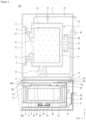
FIGS. 1 and2 illustrate examples of a laundry treating apparatus. -
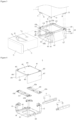
FIGS. 3 and 4 illustrate examples of a first cabinet provided in a laundry treating apparatus. -
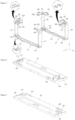
FIG. 5 illustrates an example of a first frame and a second frame. -
FIG. 6 illustrates an example of a first frame upper body. -
FIG. 7 illustrates an example of a second frame upper body. - Hereinafter, preferred embodiments of the present disclosure will be described in detail with reference to the accompanying drawings.
- A laundry treating apparatus may be provided with only a first treating apparatus L that is a drawer type laundry treating apparatus, or may be provided with the first treating apparatus L and a second treating apparatus T arranged on the first treating apparatus.
FIG. 1 illustrates that thelaundry treating apparatus 100 is provided with both a first treating apparatus L and a second treating apparatus T as an example. - The first treating apparatus L is provided to include a cabinet 6 (first cabinet), a drawer drawn out from the first cabinet, a tub 8 (first tub) provided in the drawer, providing a space where water is stored, and a drum 9 (first drum) provided inside the
first tub 8, storing laundry therein. - As shown in
FIG. 2 , anoutlet 699 is provided on afront surface 698 of thefirst cabinet 6, and thedrawer 7 includes adrawer body 71 drawn out from thefirst cabinet 6 through theoutlet 699, and adrawer panel 73 fixed to the drawer body, opening or closing theoutlet 699. - The
drawer body 71 may be provided in a hexahedral shape, and a first drawer throughhole 71a and a second drawer throughhole 71b for communicating the inside of thedrawer body 71 with the outside of thedrawer body 71 may be provided on an upper surface of thedrawer body 71. The first drawer throughhole 71a is a means for supplying laundry to thefirst drum 9, and the second drawer throughhole 71b is a means for supplying water to thefirst tub 8, and a detailed description of the first drawer throughhole 71a and the second drawer throughhole 71b will be described later. - The
drawer panel 73 is fixed to a front surface of thedrawer body 71 and located outside thefirst cabinet 6, and may be provided in a shape capable of opening or closing theoutlet 699. - The case that the
drawer panel 73 opens theoutlet 699 means that thedrawer panel 73 moves along a direction (+Z axis direction) far away from thefront surface 698 of the first cabinet and therefore theoutlet 699 is externally exposed. The case that thedrawer panel 73 closes theoutlet 699 means that theoutlet 699 is covered with thedrawer panel 73 and therefore is not externally exposed. - The
drawer panel 73 may include a control panel 75 (first control panel). Thefirst control panel 75 may be provided with an input unit for receiving a control command from a user, and a display unit for providing the user with information related to an operation of the first treating apparatus. - The
first tub 8 may be provided in a hollow cylindrical shape and fixed into thedrawer body 71 through afirst tub support 84. An inlet 81 (first inlet) and asupply hole 82 are provided on an upper surface of thefirst tub 8. Thefirst inlet 81 is preferably located below the first drawer throughhole 71a, and thesupply hole 82 may be located below the second drawer throughhole 71b. - The
first inlet 81 is opened or closed by a door 83 (first door), and thefirst door 83 may rotatably be fixed to the upper surface of thefirst tub 8 or may rotatably be fixed to the upper surface of thedrawer body 71.FIG. 2 illustrates that thefirst door 83 is coupled to the upper surface of the first tub through a hinge as an example. In this case, thefirst door 83 should be provided in a shape that can be rotated toward a direction far away from the upper surface of thefirst tub 8 through the first throughhole 71a. - The
first tub 8 is supplied with water through a water supply (first water supply), and the water stored in thefirst tub 8 is discharged from the first tub through a drainage unit (first drainage unit). - The first water supply is provided to include a first
water supply pipe 85 inserted into the second drawer throughhole 71b, connecting a water supply source (not shown) with thesupply hole 82, and afirst valve 86 for opening or closing the firstwater supply pipe 85 by means of a first controller (not shown). The first drainage unit is provided to include a first drainage pipe 88 guiding the water in thefirst tub 8 to the outside of thefirst cabinet 6, and afirst pump 87 allowing the water to move along the first drainage pipe 88. - Since the
drawer body 71 is provided to move along a length direction (Z axis direction) of thefirst cabinet 6, the firstwater supply pipe 85 and the first drainage pipe 88 may be provided as pipes, each of which has an elastic length. - *43The
first drum 9 is provided in a hollow cylindrical shape, and includes afirst drum inlet 91 and acommunication hole 93 on its upper surface, wherein thefirst drum inlet 91 is communicated with thefirst inlet 81, and thecommunication hole 93 is provided to pass through a circumferential surface and a bottom surface of the first drum. Thefirst drum inlet 91 is located below thefirst inlet 81. Therefore, the user may supply laundry to thefirst drum 9 through the first drawer throughhole 71a, thefirst inlet 81, and thefirst drum inlet 91. - The
communication hole 93 is a means for communicating the inside of thefirst drum 9 with thefirst tub 8. Therefore, the water supplied to thefirst tub 8 is supplied to the laundry inside the first drum through thecommunication hole 93, and the water and particles remaining in laundry are discharged to thefirst tub 8 through thecommunication hole 93. - The
first drum 9 is rotated through a first driver, and the first driver may be provided with afirst stator 95, afirst rotor 97, and a firstrotary shaft 99. Thefirst stator 95 is a means fixed to the bottom surface of thefirst tub 8, forming a rotating electric field, thefirst rotor 97 is a means rotated by the rotating electric field, and the firstrotary shaft 99 is a means provided to pass through the bottom surface of the first tub, connecting thefirst drum 9 with thefirst rotor 97. - The second treating apparatus T includes a
second cabinet 1 fixed to an upper surface of thefirst cabinet 6, asecond inlet 113 provided on afront surface 11 of the second cabinet, asecond door 12 opening or closing the second inlet, asecond tub 3 provided inside the second cabinet to provide a space where the water is stored and communicated with the second inlet, and asecond drum 4 rotatably provided inside the second tub to provide a space where laundry supplied through the second inlet is stored. If the second treating apparatus T is located on the first treating apparatus L, vibration and noise generated in the first treating apparatus L during rotation of thefirst drum 9 may be attenuated, and the height of thesecond inlet 113 may become high, whereby the user may conveniently insert or draw out laundry into or from the second treating apparatus T. - As shown in
FIG. 1 , thefront surface 11 of the second cabinet means a surface toward the same direction as thefront surface 698 of the first cabinet in the space provided by the second cabinet, and asecond controller 111 may be provided on thefront surface 11 of thesecond cabinet 1. Thesecond controller 111 may include a second input unit for receiving a control command from a user, and a second display unit for displaying information related to an operation of the second treating apparatus. - The second treating apparatus T is fixed to the upper surface of the
first cabinet 6 through a plurality of legs provided on abottom surface 14 of the second cabinet. That is, the legs are means for supporting the second treating apparatus T, and may be provided at each corner of thebottom surface 14.FIG. 1 illustrates that the legs are provided as a firstfront leg 15, a secondfront leg 16, a first rear leg 17 (seeFIG. 2 ), and a secondrear leg 18, as an example. - The
second tub 3 may be provided in a hollow cylindrical shape, and asecond tub inlet 31 may be provided on a front surface of thesecond tub 3. Thesecond tub inlet 31 may be connected to thesecond inlet 113 through a corrugated type gasket. - The
second tub 3 is fixed into thesecond cabinet 1 through asecond tub support 33, and thesecond tub support 33 may be provided with a damper for fixing a lower area of the second tub to thebottom surface 14 of the second cabinet, and a spring for fixing an upper area of the second tub to the second cabinet. - The second tub is supplied with water through the second water supply, and discharges the water stored in the second tub to the outside of the second cabinet. The second water supply may be provided to include a second
water supply pipe 35 connecting the water supply source with the second tub3, and asecond valve 37 for opening or closing the secondwater supply pipe 35 in accordance with a control signal of a second controller (not shown). The second drainage unit may be provided to include asecond drainage pipe 39 guiding the water in thesecond tub 3 to the outside of thesecond cabinet 1, and asecond pump 38 allowing the water to move along thesecond drainage pipe 39. - The
second drum 4 may be provided in a hollow cylindrical shape, and may include asecond drum inlet 41 on its front surface, wherein thesecond drum inlet 41 is communicated with thesecond tub inlet 31. A plurality of communication holes 43 may be provided on a front surface, a circumferential surface and a rear surface of thesecond drum 4. - The
second drum 4 is rotated through a second driver, and the second driver may be provided to include asecond stator 45 fixed to a rear surface of thesecond tub 3, forming a rotating field, asecond rotor 46 rotated by the rotating field, and a secondrotary shaft 47 provided to pass through the rear surface of thesecond tub 3, connecting thesecond drum 4 with thesecond rotor 46. - The second treating apparatus T may further include a joint unit for fixing the
second cabinet 1 to the first treating apparatus L.FIG. 3 illustrates that the joint unit includes a first front joint plate 51, a second frontjoint plate 53, a first rear joint plate (not shown), a second rearjoint plate 55, a first left j oint plate 52, a first right j oint plate 54, a second left j oint plate (not shown), and a second rightjoint plate 56, as an example. - The first front joint plate 51 and the second front
joint plate 53 may be provided to be protruded from thebottom surface 14 of the second cabinet to be parallel with thefront surface 11 of the second cabinet, and the first rear joint plate and the second rearjoint plate 55 may be provided to be protruded from thebottom surface 14 of the second cabinet to be parallel with the rear surface of the second cabinet. - The first left joint plate 52 and the second left joint plate may be provided to be protruded from the
bottom surface 14 of the second cabinet to be parallel with the left side of the second cabinet, and the first right joint plate 54 and the second rightjoint plate 56 may be provided to be protruded from thebottom surface 14 of the second cabinet to be parallel with the right side of the second cabinet. - As shown in
FIG. 3 , the joint unit may be provided to include only the first front joint plate 51, the second frontjoint plate 53, the first rear joint plate (not shown), and the second rearjoint plate 55, or may be provided to include only the first left joint plate 52, the first right joint plate 54, the second left joint plate (not shown), and the second rightjoint plate 56. - As shown in
FIG. 4 , thefirst cabinet 6 provided in the first treating apparatus includes first andsecond frames drawer 7, abase panel 68 fixed to the first and second frames, forming the bottom surface of thefirst cabinet 6, and acover 69 fixed to the first and second frames, forming the upper surface of thefirst cabinet 6 and both sides of thefirst cabinet 6. - The
base panel 68 may be made of a material lighter than theframes cover 69. That is, if theframes cover 69 are made of a metal material, thebase panel 68 may be made of plastic. This is to minimize a weight of thefirst cabinet 6 and reduce the manufacturing cost. - The
base panel 68 includes afirst slide 77 providing a moving path of thedrawer 7, and first andsecond supports second slides - The
first support 683 and thesecond support 685 are provided in thebase panel 68 along a direction where thedrawer body 71 is drawn out, and an interval between thefirst support 683 and thesecond support 685 should be set to be longer than a width (X axis direction length of the drawer body) of thedrawer body 71. Considering minimization of the manufacturing cost and easiness of assembly, thebase panel 68, thefirst support 683 and thesecond support 685 may be provided in one body. The case that thebase panel 68, thefirst support 683 and thesecond support 685 are provided in one body means that thefirst support 683 and thesecond support 685 are fixed to thebase panel 68 through a manufacturing method such as injection molding without a joint member. - The
first slide 77 may include a firstfixed body 771 fixed to thefirst support 683, and a firstdetachable body 773 having one end fixed to thedrawer body 71 and the other end detachably coupled to the firstfixed body 771. Likewise, thesecond slide 79 may include a secondfixed body 791 fixed to thesecond support 685, and a firstdetachable body 793 having one end fixed to thedrawer body 71 and the other end detachably coupled to the secondfixed body 791. The firstfixed body 771 and the secondfixed body 791 may respectively be fixed to thefirst support 683 and thesecond support 685 by a joint means such as a bolt. - Meanwhile, a panel through
hole 681 may be provided in thebase panel 68, and may be a means for allowing the external air for cooling of the first driver to enter the inside of thefirst cabinet 6. - The
cover 69 includes anupper panel 691 forming the upper surface of thefirst cabinet 6, afirst side panel 696 forming the left side of the first cabinet, and asecond side panel 697 forming the right side of the first cabinet. Theupper panel 691, thefirst side panel 696 and thesecond side panel 697 may be provided in such a manner that both ends of one metal plate are downwardly bent. In this case, theoutlet 699 formed on thefront surface 698 of thefirst cabinet 6 is formed by thecover 69 and thebase panel 68. - Although not shown, the laundry treating apparatus may further include a rear panel forming the rear surface of the
first cabinet 6. Preferably, the rear panel is detachably coupled to the rear of thecover 69 or thesecond frame 62. Since the first water supply, the first drainage are located in a rear area of thefirst cabinet 6, if the rear panel is detachably provided at the rear of thesecond frame 62 or thecover 69, it will be easy to check and repair the first water supply or the first drainage. - The
first frame 61 and thesecond frame 62 are means for supporting thecover 69 and thebase panel 68. - As shown in
FIG. 5 , thefirst frame 61 may include afirst frame body 611 of a bar shape provided to form the bottom surface of thefirst frame 61 to allow the bottom surface of thebase panel 68 to be fixed thereto, a first frame first side body 612 extended from one end of thefirst frame body 611 along a height direction (Y axis direction) of the drawer, a first framesecond side body 615 extended from the other end of thefirst frame body 611 along a height direction of the drawer, and a first frame upper body 618 (seeFIG. 4 ) connecting the first frame first side boy 612 with the first framesecond side body 615. - The
first frame body 611, the first frame first side body 612, and the first framesecond side body 615 may be provided in such a manner that one metal is bent in a U shape through press molding. - As shown in
FIG. 4 , the first frameupper body 618 is provided to form the upper surface of thefirst frame 61, and provides a space where theupper panel 691 is fixed. Also, an interval between a free end of the first frame first side body 612 and a free end of the first framesecond side body 615 is maintained (strength of the first frame is reinforced). The first frameupper body 618 may be made of a material lighter than thefirst frame body 611, for example, plastic. If the first frameupper body 618 is made of a material lighter than metal, a weight and manufacturing cost of thefirst cabinet 6 may be minimized. - A first outlet communication hole communicated with the
outlet 699 should be provided in thefirst frame 61 such that thedrawer body 71 may pass through thefirst frame 61. The first outlet communication hole is formed by thefirst frame body 611, the first frame first side body 612, the first framesecond side body 615, and the first frameupper body 618. - A first front
leg accommodating unit 618a providing a space in which the firstfront leg 15 provided in the second treating apparatus is accommodated and a second front legaccommodating unit 618b providing a space in which the secondfront leg 16 provided in the second treating apparatus is accommodated are provided in the first frameupper body 618. - The first front
leg accommodating unit 618a is protruded from the first frameupper body 618 to form a space in which the firstfront leg 15 is accommodated, and the second front legaccommodating unit 618b is protruded from the first frameupper body 618 to form a space in which the secondfront leg 16 is accommodated. - The first front
leg accommodating unit 618a is exposed to the upper surface of thefirst cabinet 6 through a first upper throughhole 692 provided to pass through theupper panel 691, and the second front legaccommodating unit 618b is exposed to the outside of thefirst cabinet 6 through a second upper throughhole 693 provided to pass through theupper panel 691. - As shown in
FIG. 5 , thesecond frame 62 includes asecond frame body 621 of a bar shape provided to form the bottom surface of thesecond frame 62, supporting the bottom surface of thebase panel 68, a second framefirst side body 622 extended from one end of thesecond frame body 621 along a height direction (Y axis direction) of the drawer, a second framesecond side body 625 extended from the other end of thesecond frame body 621 along a height direction of the drawer, and a second frameupper body 628 forming the upper surface of thesecond frame 62. - The
second frame body 621, the second framefirst side body 622, and the second framesecond side body 625 may be provided in such a manner that one metal is bent in a U shape through press molding. The second frameupper body 628 may be made of a plastic material. - As shown in
FIG. 4 , the second frameupper body 628 is provided to connect the second framefirst side body 622 with the second framesecond side body 625 and provides a space where theupper panel 691 is fixed. - A second outlet communication hole communicated with the
outlet 699 should be provided in thesecond frame 62. The second outlet communication hole is formed by thesecond frame body 621, the second framefirst side body 622, the second framesecond side body 625, and the second frameupper body 628. - A first rear
leg accommodating unit 628a providing a space in which the firstrear leg 17 provided in the second treating apparatus is accommodated and a second rearleg accommodating unit 628b providing a space in which the secondrear leg 18 provided in the second treating apparatus is accommodated are provided in the second frameupper body 628. - The first rear
leg accommodating unit 628a is protruded from the second frameupper body 628 to form a space in which the firstrear leg 17 is accommodated, and the second rearleg accommodating unit 628b is protruded from the second frameupper body 628 to form a space in which the secondrear leg 18 is accommodated. - The first rear
leg accommodating unit 628a is exposed to the upper surface of thefirst cabinet 6 through a third upper throughhole 694 provided to pass through theupper panel 691, and the second rearleg accommodating unit 628b is exposed to the outside of thefirst cabinet 6 through a fourth upper throughhole 695 provided to pass through theupper panel 691. - Since the first front
leg accommodating unit 618a and the second front legaccommodating unit 618b are provided in the first frameupper body 618 and the first rearleg accommodating unit 628a and the second rearleg accommodating unit 628b are provided in the second frameupper body 628, the laundry treating apparatus needs to assemble separate leg accommodating units in theupper panel 691 after fixing the cover 60 to theframes - It is assumed that the first front
leg accommodating unit 618a and the second front legaccommodating unit 618b are provided to detached from the first frameupper body 618 and the first rearleg accommodating unit 628a and the second rearleg accommodating unit 628b are provided to be detached from the second frameupper body 628. In this case, a worker should assemble the first frontleg accommodating unit 618a, the second front legaccommodating unit 618b, the first rearleg accommodating unit 628a and the second rearleg accommodating unit 628b in each corner of theupper panel 691 by using a bolt, etc. after assembling thecover 69 in the twoframes upper body 618 and the second frameupper body 628 reduce the working time and minimize the number of components. - As shown in
FIG. 5 , in order to enhance strength of thecabinet 6, thelaundry treating apparatus 100 may further include afirst bracket 641 having one end fixed to thefirst frame body 611 and the other end fixed to the first frame first side body 612, asecond bracket 642 having one end fixed to thefirst frame body 611 and the other end fixed to the first framesecond side body 615, athird bracket 643 having one end fixed to thesecond frame body 621 and the other end fixed to the second framefirst side body 622, and afourth bracket 644 having one end fixed to thesecond frame body 621 and the other end fixed to the second framesecond side body 625. - Moreover, in order to enhance strength of the
first cabinet 6 by stably supporting the first frameupper body 618 and the second frameupper body 628, thefirst frame 61 may further include a firstfront extension body 612a, a secondfront extension body 615a, a firstrear extension body 622a, and a secondrear extension body 625a. - The first
front extension body 612a may be made of a metal plate extended from the first frame first side body 612 to the first framesecond side body 615, and the secondfront extension body 615a may be made of a metal plate extended from the first framesecond side body 615 to the first frame first side body 612. - Likewise, the first
rear extension body 622a may be made of a metal plate extended from the second framefirst side body 622 to the second framesecond side body 625, and the secondrear extension body 625a may be made of a metal plate extended from the second framesecond side body 625 to the second framefirst side body 622. - The
first frame body 611, the first frame first side body 612, the first framesecond side body 615, the firstfront extension body 612a, and the secondfront extension body 615a may be provided in such a manner that one metal is bent in a U shape through press molding. In this case, the first frame first side body 612 may be connected with the firstfront extension body 612a through a firstupper bracket 645, and the first framesecond side body 615 may be connected with the secondfront extension body 615a through a secondupper bracket 646. - One end of the first
upper bracket 645 may be fixed to the first frame first side body 612 through a joint means such as a bolt, and the other end of the firstupper bracket 645 may be fixed to the firstfront extension body 612a through a joint means such as a bolt. Likewise, one end of the secondupper bracket 646 may be fixed to the first framesecond side body 615 through a joint means such as a bolt, and the other end of the secondupper bracket 646 may be fixed to the secondfront extension body 615a through a joint means such as a bolt. - The
second frame body 621, the second framefirst side body 622, the second framesecond side body 625, the firstrear extension body 622a, and the secondrear extension body 625a may be provided in such a manner that one metal is bent in a U shape through press molding. In this case, the second framefirst side body 622 may be connected with the firstrear extension body 622a through a thirdupper bracket 647, and the second framesecond side body 625 may be connected with the secondrear extension body 625a through a fourthupper bracket 648. The firstupper bracket 645, the secondupper bracket 646, the thirdupper bracket 647 and the fourthupper bracket 648 may be made of a metal material. - The first
front extension body 612a may be provided with a firstfront connection plate 613 to which a first front joint plate 51 of the second treating apparatus T is fixed through theupper panel 691 of the first cabinet and the first frameupper body 618, and the secondfront extension body 615a may be provided with a secondfront connection plate 616 to which a second frontjoint plate 53 of the second treating apparatus T is fixed through theupper panel 691 of the first cabinet and the first frameupper body 618. - The first
front connection plate 613 may be made of a metal plate projected from the firstfront extension body 612a toward theupper panel 691 of the first cabinet (projected toward a height direction of the first cabinet). Preferably, the firstfront extension body 612a and the firstfront connection plate 613 are provided in one body. - Likewise, the second
front connection plate 616 may be made of a metal plate projected from the secondfront extension body 615a toward theupper panel 691 of the first cabinet. Preferably, the secondfront extension body 615a and the secondfront connection plate 616 are provided in one body. - As shown in
FIG. 6 , the first frameupper body 618 should be provided with a first front connection plate throughhole 618c and a second front connection plate throughhole 618d through which the firstfront connection plate 613 and the secondfront connection plate 616 pass, and theupper panel 691 should be provided with a first front connection plate cabinet through hole (not shown) and a second front connection plate cabinet through hole (not shown). - As shown in
FIG. 5 , the firstrear extension body 622a may be provided with a firstrear connection plate 623 to which the first rear joint plate of the second treating apparatus is fixed through theupper panel 691 of the first cabinet and the second frameupper body 628, and the secondrear extension body 625a may be provided with a secondrear connection plate 626 to which the second rearjoint plate 55 of the second treating apparatus T is fixed through theupper panel 691 and the second frameupper body 628. - As shown in
FIG. 7 , the second frameupper body 628 should be provided with a first rear connection plate throughhole 628c and a second rear connection plate throughhole 628d through which the firstrear connection plate 623 and the secondrear connection plate 626 pass, and theupper panel 691 should be provided with a first rear connection plate cabinet through hole (not shown) and a second rear connection plate cabinet through hole (not shown). - In order to enhance strength of the
first cabinet 6 along a length direction (Z axis direction), thefirst frame 61 may further include a third front extension body 612b, a fourthfront extension body 643, a thirdrear extension body 622b, and a fourthrear extension body 625b. - The third front extension body 612b may be made of a metal plate extended from the first frame first side body 612 to the second frame
first side body 622, and the fourth front extension body 615b may be made of a metal plate extended from the first framesecond side body 615 to the second framesecond side body 625. The third front extension body 612b may be fixed to the first frame first side body 612 through a bolt, and the fourth front extension body 615b may be fixed to the first framesecond side body 615 through a bolt. - The third
rear extension body 622b may be made of a metal plate extended from the second framefirst side body 622 to the first frame first side body 612, and the fourthrear extension body 625b may be made of a metal plate extended from the second framesecond side body 625 to the first framesecond side body 615. The thirdrear extension body 622b may be fixed to the second framefirst side body 622 through a bolt, and the fourthrear extension body 625b may be fixed to the second framesecond side body 625 through a bolt. - The third front extension body 612b is provided with a first
left connection plate 614 to which the first left joint plate 52 of the second treating apparatus T is fixed through theupper panel 691 of the first cabinet and the first frameupper body 618, and the fourth front extension body 615b is provided with a firstright connection plate 617 to which the first right joint plate 54 of the second treating apparatus T is fixed through theupper panel 691 and the first frameupper body 618. - As shown in
FIG. 6 , the first frameupper body 618 should be provided with a first left connection plate throughhole 618e and a first right connection plate throughhole 618f through which the firstleft connection plate 614 and the firstright connection plate 617 pass, and theupper panel 691 should be provided with a first left connection plate cabinet through hole (not shown) and a second right connection plate cabinet through hole (not shown). - Meanwhile, the third
rear extension body 622b is provided with a secondleft connection plate 624 to which the second left joint plate (not shown) of the second treating apparatus T is fixed through theupper panel 691 and the second frameupper body 628, and the fourthrear extension body 625b is provided with a secondright connection plate 627 to which the second right joint plate 54 of the second treating apparatus T is fixed through theupper panel 691 and the second frameupper body 628. - As shown in
FIG. 7 , the second frameupper body 628 should be provided with a second left connection plate through hole 628e and a second right connection plate throughhole 628f through which the secondleft connection plate 624 and the secondright connection plate 627 pass, and theupper panel 691 should be provided with a second left connection plate cabinet through hole (not shown) and a second right connection plate cabinet through hole (not shown). - The first frame
upper body 618 and the second frameupper body 628 may be provided in the same structure. In this case, the first frameupper body 618 may be the second frame upper body if rotated at 180°. - It will be apparent to those skilled in the art that the present disclosure may be embodied in other specific forms without departing from the spirit and essential characteristics of the invention. Thus, the above embodiments are to be considered in all respects as illustrative and not restrictive. The scope of the invention should be determined by reasonable interpretation of the appended claims and all change which comes within the equivalent scope of the invention are included in the scope of the invention.
- It follows a list of examples:
- 1. A laundry treating apparatus comprising: a cabinet provided with an outlet; a drawer drawn out from the cabinet through the outlet; a tub provided inside the drawer to provide a space in which water is stored, having an inlet on its upper surface; a drawer provided on the upper surface of the drawer or an upper surface of the tub, opening or closing the inlet; a drum rotatably provided inside the tub, storing laundry therein; and a drum inlet provided on an upper surface of the drum, allowing laundry supplied to the inlet to enter the inside of the drum, wherein the cabinet includes: a first frame provided with a first outlet communication hole communicated with the outlet, at least a part of the first frame being made of a metal material; a second frame provided to be spaced apart from the first frame along a moving direction of the drawer, having a second outlet communication hole communicated with the outlet, at least a part of the second frame being made of a metal material; a base panel fixed to the first frame and the second frame, forming a bottom surface of the cabinet, and made of a nonmetal material lighter than metal; and a cover fixed to the first frame and the second frame, forming an upper surface and both sides of the cabinet, and made of a metal material.
- 2. The laundry treating apparatus of example 1, wherein the base panel is made of a plastic material.
- 3. The laundry treating apparatus of example 1, further comprising: a first support and a second support in the base panel along a direction where the drawer is drawn out and spaced apart from each other at an interval longer than a width of the drawer; a first fixed body fixed to the first support; a first detachable body having one end fixed to the drawer and the other end detachably coupled to the first fixed body; a second fixed body fixed to the second support; and a second detachable body having one end fixed to the drawer and the other end detachably coupled to the second fixed body.
- 4. The laundry treating apparatus of example 3, wherein the base panel, the first support and the second support are provided in one body through injection molding.
- 5. The laundry treating apparatus of example 3, further comprising: a stator provided on a bottom surface of the tub, generating a rotating field; a rotor rotated by the rotating field; a rotary shaft provided to pass through the bottom surface of the tub, connecting the rotor with a bottom surface of the drum; and a panel through hole provided to pass through the base panel, allowing the air to the inside of the cabinet.
- 6. The laundry treating apparatus of example 1, wherein the first frame includes: a first frame body of a bar shape provided to form a bottom surface of the first frame, supporting a lower surface of the base panel, and made of a metal material; a first frame first side body of a metal material extended from one end of the first frame body along a height direction of the drawer; a first frame second side body of a metal material extended from the other end of the first frame body along the height direction of the drawer; and a first frame upper body provided to connect the first frame first side body with the first frame second side body, forming an upper surface of the first frame, and made of a nonmetal material lighter than metal, and the second frame includes: a second frame body of a bar shape provided to form a bottom surface of the second frame, supporting the lower surface of the base panel, and made of a metal material; a second frame second side body of a metal material extended from one end of the second frame body along the height direction of the drawer; a second frame second side body of a metal material extended from the other end of the second frame body along the height direction of the drawer; and a second frame upper body provided to connect the second frame first side body with the second frame second side body, forming an upper surface of the second frame, and made of a nonmetal material.
- 7. The laundry treating apparatus of example 6, wherein the first frame upper body and the second frame upper body are made of a plastic material.
- 8. The laundry treating apparatus of example 6, wherein the first frame body, the first frame first side body and the first frame second side body are provided such that one metal is bent in a U shape through press molding, and the second frame body, the second frame first side body and the second frame second side body are provided such that one metal is bent in a U shape through press molding.
- 9. The laundry treating apparatus of example 8, further comprising: a first bracket having one end fixed to the first frame body and the other end fixed to the first frame first side body; a second bracket having one end fixed to the first frame body and the other end fixed to the first frame second side body; a third bracket having one end fixed to the second frame body and the other end fixed to the second frame first side body; and a fourth bracket having one end fixed to the second frame body and the other end fixed to the second frame second side body.
- 10. The laundry treating apparatus of example 6, further comprising: a second cabinet located on the cabinet; a second drum rotatably provided inside the second cabinet, providing a space in which laundry is stored; a first front leg and a second front leg provided to correspond to the first frame upper body in a space provided by a bottom surface of the second cabinet; a first rear leg and a second rear leg provided to correspond to the second frame upper body in the space provided by the bottom surface of the second cabinet; a first front leg accommodating unit provided in the first frame upper body to pass through the upper surface of the cabinet, providing a space in which the first front leg is accommodated; a second front leg accommodating unit provided in the first frame upper body to pass through the upper surface of the cabinet, providing a space in which the second front leg is accommodated; a first rear leg accommodating unit provided in the second frame upper body to pass through the upper surface of the cabinet, providing a space in which the first rear leg is accommodated; and a second rear leg accommodating unit provided in the second frame upper body to pass through the upper surface of the cabinet, providing a space in which the second rear leg is accommodated.
- 11. The laundry treating apparatus of example 10, further comprising: a first front extension body extended from the first frame first side body toward the first frame second side body; a second front extension body extended from the first frame second side body toward the first frame first side body; a first rear extension body extended from the second frame first side body toward the second frame second side body; a second rear extension body extended from the second frame second side body toward the second frame first side body; a first front connection plate provided in the first front extension body and provided to pass through the first frame upper body and the upper surface of the first cabinet; a second front connection plate provided in the second front extension body and provided to pass through the first frame upper body and the upper surface of the first cabinet; a first rear connection plate provided in the first rear extension body and provided to pass through the second frame upper body and the upper surface of the first cabinet; a first front joint plate provided on the bottom surface of the second cabinet and jointed to the first front connection plate; a second front joint plate provided on the bottom surface of the second cabinet and jointed to the second front connection plate; a first rear j oint plate provided on the bottom surface of the second cabinet and jointed to the first rear connection plate; and a second rear joint plate provided on the bottom surface of the second cabinet and jointed to the second rear connection plate.
- 12. The laundry treating apparatus of example 11, wherein the first frame body, the first frame first side body, the first frame second side body, the first front extension body, and the second front extension body are provided such that one metal is bent in a U shape through press molding, and the second frame body, the second frame first side body, the second frame second side body, the first rear extension body, and the second rear extension body are provided such that one metal is bent in a U shape through press molding.
- 13. The laundry treating apparatus of example 12, further comprising: a first upper bracket having one end fixed to the first frame first side body and the other end fixed to the first front extension body; a second upper bracket having one end fixed to the first frame second side body and the other end fixed to the second front extension body; a third upper bracket having one end fixed to the second frame first side body and the other end fixed to the first rear extension body; and a fourth upper bracket having one end fixed to the second frame second side body and the other end fixed to the second rear extension body.
- 14. The laundry treating apparatus of example 10, further comprising: a third front extension body extended from the first frame first side body toward the second frame first side body; a fourth front extension body extended from the first frame second side body toward the second frame second side body; a third rear extension body extended from the second frame first side body toward the first frame first side body; a fourth rear extension body extended from the second frame second side body toward the first frame second side body; a first left connection plate provided in the third front extension body and provided to pass through the first frame upper body and the upper surface of the cabinet; a first right connection plate provided in the fourth front extension body and provided to pass through the first frame upper body and the upper surface of the cabinet; a second left connection plate provided in the third rear extension body and provided to pass through the second frame upper body and the upper surface of the cabinet; a second right connection plate provided in the fourth rear extension body and provided to pass through the second frame upper body and the upper surface of the cabinet; a first left joint plate provided on the bottom surface of the second cabinet and jointed to the first left connection plate; a first right joint plate provided on the bottom surface of the second cabinet and jointed to the first right connection plate; a second left joint plate provided on the bottom surface of the second cabinet and jointed to the second left connection plate; and a second right joint plate provided on the bottom surface of the second cabinet and jointed to the second right connection plate.
Claims (15)
- A laundry treating apparatus (100) comprising:a cabinet (6) provided with an outlet (699);a drawer (7) configured to be drawn out from the cabinet (6) through the outlet (699);a tub (8) provided inside the drawer to provide a space in which water is stored, having an inlet (81) on its upper surface;a door (83) provided on the upper surface of the drawer (7) or an upper surface of the tub (8), for opening or closing the inlet (81);a drum (9) rotatably provided inside the tub (8), for storing laundry therein; anda drum inlet (91) provided on an upper surface of the drum (9), allowing laundry supplied to the inlet (81) to enter the inside of the drum (9);wherein the cabinet (6) comprises:a first frame (61);a second frame (62) provided to be spaced apart from the first frame (61) along a moving direction of the drawer (7);a base panel (68) fixed to the first frame (61) and the second frame (62), forming a bottom surface of the cabinet (6); anda cover (69) fixed to the first frame (61) and the second frame (62), forming an upper surface and both sides of the cabinet (6);wherein:- the first frame (61) comprises: a first frame first side body (612) extended from a front one end of the base panel (68) along a height direction of the drawer (7), a first frame second side body (615) extended from the other front end of the base panel (68) along the height direction of the drawer (7) and a first frame upper body (618) provided to connect the first frame first side body (612) with the first frame second side body (615), forming an upper surface of the first frame (61), and the second frame (62) comprises: a second frame first side body (622) extended from a rear one end of the base panel (68) along the height direction of the drawer (7), a second frame second side body (625) extended from the other rear end of the base panel (68) along the height direction of the drawer and a second frame upper body (628) provided to connect the second frame first side body (622) with the second frame second side body (625), forming an upper surface of the second frame (62); or- the first frame (61) comprises: a first frame body (611) of a bar shape provided to form a bottom surface of the first frame (61), a first frame first side body (612) extended from one end of the first frame body (611) along a height direction of the drawer (7), a first frame second side body (615) extended from the other end of the first frame body (611) along the height direction of the drawer (7) and a first frame upper body (618) provided to connect the first frame first side body (612) with the first frame second side body (615), forming an upper surface of the first frame (61), and the second frame (62) comprises: a second frame body (621) of a bar shape provided to form a bottom surface of the second frame (62), a second frame first side body (622) extended from one end of the second frame body (621) along the height direction of the drawer (7), a second frame second side body (625) extended from the other end of the second frame body (621) along the height direction of the drawer and a second frame upper body (628) provided to connect the second frame first side body (622) with the second frame second side body (625), forming an upper surface of the second frame (62).
- The laundry treating apparatus (100) of claim 1, wherein the cabinet (6) further comprises:a first front extension body (612a) extended from the first frame first side body (612) toward the first frame second side body (615);a second front extension body (615a) extended from the first frame second side body (615) toward the first frame first side body (612);a first rear extension body (622a) extended from the second frame first side body (622) toward the second frame second side body (625); anda second rear extension body (625a) extended from the second frame second side body (625) toward the second frame first side body (622).
- The laundry treating apparatus (100) of claim 2, wherein the cabinet (6) further comprises:a third front extension body (612b) extended from the first frame first side body (612) toward the second frame first side body (622);a fourth front extension body (643) extended from the first frame second side body (615) toward the second frame second side body (625);a third rear extension body (622b) extended from the second frame first side body (622) toward the first frame first side body (612); anda fourth rear extension body (625b) extended from the second frame second side body (625) toward the first frame second side body (615).
- The laundry treating apparatus (100) of claim 2 or 3, wherein the cabinet (6) further comprises:a first upper bracket (645) having one end fixed to the first frame first side body (612) and the other end fixed to the first front extension body (612a);a second upper bracket (646) having one end fixed to the first frame second side body (615) and the other end fixed to the second front extension body (615a);a third upper bracket (647) having one end fixed to the second frame first side body (622) and the other end fixed to the first rear extension body (622a); anda fourth upper bracket (648) having one end fixed to the second frame second side body (625) and the other end fixed to the second rear extension body (625a).
- The laundry treating apparatus (100) of any one of the preceding claims when depending on claims 2 and 3,wherein the cabinet (6) further comprises:- a first front connection plate (613) provided in the first front extension body (612a) and provided to pass through the first frame upper body (618) and the upper surface of the cabinet (6),- a second front connection plate (616) provided in the second front extension body (615a) and provided to pass through the first frame upper body (618) and the upper surface of the cabinet (6),- a first rear connection plate (623) provided in the first rear extension body (622a) and provided to pass through the second frame upper body (628) and the upper surface of the cabinet (6), and- a second rear connection plate (626) provided in the second rear extension body (625a) and provided to pass through the second frame upper body (628) and the upper surface of the cabinet (6); and/orwherein the cabinet (6) further comprises:- a first left connection plate (614) provided in the third front extension body (612b) and provided to pass through the first frame upper body (618) and the upper surface of the cabinet (6),- a first right connection plate (617) provided in the fourth front extension body (643) and provided to pass through the first frame upper body (618) and the upper surface of the cabinet (6),- a second left connection plate (624) provided in the third rear extension body (622b) and provided to pass through the second frame upper body (628) and the upper surface of the cabinet (6), and- a second right connection plate (627) provided in the fourth rear extension body (625b) and provided to pass through the second frame upper body (628) and the upper surface of the cabinet (6).
- The laundry treating apparatus (100) of any one of the preceding claims, wherein the cabinet (6) further comprises:a first support (683) and a second support (685) in the base panel (68) along a direction where the drawer (7) is drawn out and spaced apart from each other at an interval longer than a width of the drawer (7);a first fixed body (771) fixed to the first support (683);a first detachable body (773) having one end fixed to the drawer (7) and the other end detachably coupled to the first fixed body (771);a second fixed body (791) fixed to the second support (685); anda second detachable body (793) having one end fixed to the drawer and the other end detachably coupled to the second fixed body (791).
- The laundry treating apparatus (100) of claim 6, wherein the base panel (68), the first support (683) and the second support (685) are provided in one body through injection molding.
- The laundry treating apparatus (100) of any one of the preceding claims,wherein the first frame first side body (612), the first frame second side body (615), the second frame first side body (622) and the second frame second side body (622) are made of a metal material, and the first frame upper body (618) and the second frame upper body (628) are made of a plastic material; and/orwherein the base panel (68) is made of a plastic material.
- The laundry treating apparatus (100) of any one of the preceding claims, wherein the first frame (61) comprises the first frame body (611), and the second frame (62) comprises the second frame body (621); and
wherein the first frame body (611), the first frame first side body (612) and the first frame second side body (615) are provided such that one metal is bent in a U shape through press molding, and the second frame body (621), the second frame first side body (622) and the second frame second side body (625) are provided such that one metal is bent in a U shape through press molding. - The laundry treating apparatus (100) of any one of the preceding claims when depending on claim 2, wherein the first frame (61) comprises the first frame body (611), and the second frame (62) comprises the second frame body (621); and
wherein the first frame body (611), the first frame first side body (612), the first frame second side body (615), the first front extension body (612a), and the second front extension body (615a) are provided such that one metal is bent in a U shape through press molding, and the second frame body (621), the second frame first side body (622), the second frame second side body (625), the first rear extension body (622a), and the second rear extension body (625a) are provided such that one metal is bent in a U shape through press molding. - The laundry treating apparatus (100) of any one of the preceding claims, wherein the first frame (61) comprises the first frame body (611), and the second frame (62) comprises the second frame body (621); and
wherein the cabinet (6) further comprises:a first bracket (641) having one end fixed to the first frame body (611) and the other end fixed to the first frame first side body (612); anda second bracket (642) having one end fixed to the first frame body (611) and the other end fixed to the first frame second side body (615);a third bracket (643) having one end fixed to the second frame body (621) and the other end fixed to the second frame first side body (622); anda fourth bracket (644) having one end fixed to the second frame body (621) and the other end fixed to the second frame second side body (625). - The laundry treating apparatus (100) of any one of the preceding claims,wherein the first frame upper body (618) comprises a first front leg accommodating unit (618a) and a second front leg accommodating unit (618b) for providing spaces in which front legs of a second treating apparatus are accommodated; andwherein the second frame upper body (628) comprises a first rear leg accommodating unit (628a) and a second rear leg accommodating unit (628b) for providing spaces in which rear legs of the second treating apparatus are accommodated.
- The laundry treating apparatus (100) of any one of the preceding claims when depending on claim 5,wherein the first frame upper body (618) further comprises a first front connection plate through hole (618c) and a second front connection plate through hole (618d) through which the first front connection plate (613) and the second front connection plate (616) pass, and a first left connection plate through hole (618e) and a first right connection plate through hole (618f) through which the first left connection plate (614) and the first right connection plate (617) pass; andwherein the second frame upper body (628) further comprises a first rear connection plate through hole (628c) and a second rear connection plate through hole (628d) through which the first rear connection plate (623) and the second rear connection plate (626) pass, and a second left connection plate through hole (628e) and a second right connection plate through hole (628f) through which the second left connection plate (624) and the second right connection plate (627) pass.
- The laundry treating apparatus (100) of any one of the preceding claims when depending on claim 13, further comprising:a second cabinet (1) located on the cabinet (6);a second drum (4) rotatably provided inside the second cabinet (1), providing a space in which laundry is stored;a first front leg (15) and a second front leg (16) accommodated in the spaces provided by the first front leg accommodating unit (618a) and the second front leg accommodating unit (618b) in a space provided by a bottom surface of the second cabinet (1);a first rear leg (17) and a second rear leg (18) accommodated in the spaces provided by the first rear leg accommodating unit (628a) and the second rear leg accommodating unit (628b) in the space provided by the bottom surface of the second cabinet (1).
- The laundry treating apparatus (100) of claim 14, further comprising:a first front joint plate (51) provided on the bottom surface of the second cabinet (1) and jointed to the first front connection plate (613);a second front joint plate (53) provided on the bottom surface of the second cabinet (1) and jointed to the second front connection plate (616);a first rear joint plate provided on the bottom surface of the second cabinet (1) and jointed to the first rear connection plate (623); anda second rear joint plate (55) provided on the bottom surface of the second cabinet (1) and jointed to the second rear connection plate (626).
Applications Claiming Priority (3)
| Application Number | Priority Date | Filing Date | Title |
|---|---|---|---|
| KR1020180127574A KR102531720B1 (en) | 2018-10-24 | 2018-10-24 | Laundry Treating Machine |
| EP19876185.0A EP3870749B1 (en) | 2018-10-24 | 2019-10-24 | Laundry treating apparatus |
| PCT/KR2019/014034 WO2020085807A1 (en) | 2018-10-24 | 2019-10-24 | Laundry treating apparatus |
Related Parent Applications (1)
| Application Number | Title | Priority Date | Filing Date |
|---|---|---|---|
| EP19876185.0A Division EP3870749B1 (en) | 2018-10-24 | 2019-10-24 | Laundry treating apparatus |
Publications (3)
| Publication Number | Publication Date |
|---|---|
| EP4477792A2 true EP4477792A2 (en) | 2024-12-18 |
| EP4477792A3 EP4477792A3 (en) | 2025-03-05 |
| EP4477792B1 EP4477792B1 (en) | 2026-03-18 |
Family
ID=70331623
Family Applications (2)
| Application Number | Title | Priority Date | Filing Date |
|---|---|---|---|
| EP24210941.1A Active EP4477792B1 (en) | 2018-10-24 | 2019-10-24 | Laundry treating apparatus |
| EP19876185.0A Active EP3870749B1 (en) | 2018-10-24 | 2019-10-24 | Laundry treating apparatus |
Family Applications After (1)
| Application Number | Title | Priority Date | Filing Date |
|---|---|---|---|
| EP19876185.0A Active EP3870749B1 (en) | 2018-10-24 | 2019-10-24 | Laundry treating apparatus |
Country Status (4)
| Country | Link |
|---|---|
| US (2) | US12018420B2 (en) |
| EP (2) | EP4477792B1 (en) |
| KR (1) | KR102531720B1 (en) |
| WO (1) | WO2020085807A1 (en) |
Families Citing this family (3)
| Publication number | Priority date | Publication date | Assignee | Title |
|---|---|---|---|---|
| KR102531720B1 (en) * | 2018-10-24 | 2023-05-12 | 엘지전자 주식회사 | Laundry Treating Machine |
| WO2021235847A1 (en) | 2020-05-18 | 2021-11-25 | 엘지전자 주식회사 | Clothing processing apparatus |
| WO2022262512A1 (en) * | 2021-06-18 | 2022-12-22 | 青岛海尔滚筒洗衣机有限公司 | Drawer-type clothing processing apparatus |
Family Cites Families (20)
| Publication number | Priority date | Publication date | Assignee | Title |
|---|---|---|---|---|
| EP1621660B1 (en) * | 2004-06-14 | 2010-03-10 | Samsung Electronics Co., Ltd. | Supporter for clothes washing machine and clothes drying apparatus |
| US7913419B2 (en) * | 2005-12-30 | 2011-03-29 | Whirlpool Corporation | Non-tumble clothes dryer |
| AU2007277518A1 (en) * | 2006-07-28 | 2008-01-31 | Lg Electronics Inc. | Multiple laundry treating machine |
| EP2152951B1 (en) * | 2007-05-17 | 2017-03-01 | LG Electronics Inc. | Laundry machine |
| EP2063012B1 (en) * | 2007-11-21 | 2013-09-18 | LG Electronics Inc. | Washing machine |
| KR101461951B1 (en) * | 2008-04-30 | 2014-11-14 | 엘지전자 주식회사 | Washing machine |
| KR100866461B1 (en) * | 2007-12-03 | 2008-10-31 | 전영환 | Washer pedestal |
| KR20090114781A (en) * | 2008-04-30 | 2009-11-04 | 엘지전자 주식회사 | Clothing processing device |
| KR20100108899A (en) | 2009-03-31 | 2010-10-08 | 지엘하이테크 주식회사 | Box for washing machine |
| KR101742991B1 (en) * | 2009-05-11 | 2017-06-02 | 엘지전자 주식회사 | Washing machine |
| US10081898B2 (en) * | 2010-04-30 | 2018-09-25 | Lg Electronics Inc. | Laundry apparatus |
| ITTO20110380A1 (en) * | 2011-05-02 | 2012-11-03 | Indesit Co Spa | APPARATUS FOR THE TREATMENT OF TEXTILE ITEMS |
| EP2949801B1 (en) | 2011-05-02 | 2017-10-25 | Whirlpool EMEA S.p.A | Appliance for treating textile items and auxiliary washing device |
| CN104321481B (en) * | 2012-08-23 | 2017-04-05 | Lg电子株式会社 | Auxiliary washing machine and the device for clothing processing using the auxiliary washing machine |
| US10435835B2 (en) * | 2014-05-30 | 2019-10-08 | Lg Electronics Inc. | Auxiliary washing machine and laundry treatment apparatus using the same |
| CN105624964B (en) * | 2014-10-30 | 2019-08-27 | 青岛海尔洗衣机有限公司 | A drawer type washing device |
| CN105624984B (en) | 2014-10-30 | 2019-07-12 | 青岛海尔智能技术研发有限公司 | Washing machine and its control method |
| CN104846597A (en) * | 2015-04-28 | 2015-08-19 | 无锡小天鹅股份有限公司 | Base for household appliance and household appliance with base |
| KR20170037182A (en) * | 2015-09-25 | 2017-04-04 | 엘지전자 주식회사 | Laundry Treating Apparatus |
| KR102531720B1 (en) * | 2018-10-24 | 2023-05-12 | 엘지전자 주식회사 | Laundry Treating Machine |
-
2018
- 2018-10-24 KR KR1020180127574A patent/KR102531720B1/en active Active
-
2019
- 2019-10-24 US US17/287,348 patent/US12018420B2/en active Active
- 2019-10-24 EP EP24210941.1A patent/EP4477792B1/en active Active
- 2019-10-24 WO PCT/KR2019/014034 patent/WO2020085807A1/en not_active Ceased
- 2019-10-24 EP EP19876185.0A patent/EP3870749B1/en active Active
-
2024
- 2024-05-28 US US18/676,143 patent/US12392069B2/en active Active
Also Published As
| Publication number | Publication date |
|---|---|
| EP3870749A1 (en) | 2021-09-01 |
| EP3870749B1 (en) | 2024-12-04 |
| EP3870749A4 (en) | 2022-07-27 |
| WO2020085807A1 (en) | 2020-04-30 |
| EP4477792B1 (en) | 2026-03-18 |
| KR20200046429A (en) | 2020-05-07 |
| US20240309572A1 (en) | 2024-09-19 |
| US12018420B2 (en) | 2024-06-25 |
| US20210381148A1 (en) | 2021-12-09 |
| US12392069B2 (en) | 2025-08-19 |
| EP4477792A3 (en) | 2025-03-05 |
| KR102531720B1 (en) | 2023-05-12 |
Similar Documents
| Publication | Publication Date | Title |
|---|---|---|
| US12392069B2 (en) | Laundry treating apparatus | |
| EP4617422A2 (en) | Laundry treating apparatus and assembly method of the same | |
| EP3056601B1 (en) | Clothing dryer | |
| CN102439216B (en) | Laundry machine | |
| US11066773B2 (en) | Laundry treating apparatus | |
| KR20210009689A (en) | Clothes Care Device | |
| US9032978B2 (en) | Dishwasher with a damping device and method for producing a damping device | |
| US20190368097A1 (en) | Laundry treating apparatus with drawer unlocking unit | |
| US20180347098A1 (en) | Laundry treatment apparatus | |
| AU2019206095B2 (en) | Laundry treatment apparatus | |
| CN107075777A (en) | Washing machine for clothes | |
| KR102799615B1 (en) | Laundry treating apparatus | |
| KR102316087B1 (en) | Laundry Treating Apparatus | |
| KR20170087739A (en) | Laundry Treating Apparatus |
Legal Events
| Date | Code | Title | Description |
|---|---|---|---|
| PUAI | Public reference made under article 153(3) epc to a published international application that has entered the european phase |
Free format text: ORIGINAL CODE: 0009012 |
|
| STAA | Information on the status of an ep patent application or granted ep patent |
Free format text: STATUS: REQUEST FOR EXAMINATION WAS MADE |
|
| 17P | Request for examination filed |
Effective date: 20241105 |
|
| AC | Divisional application: reference to earlier application |
Ref document number: 3870749 Country of ref document: EP Kind code of ref document: P |
|
| AK | Designated contracting states |
Kind code of ref document: A2 Designated state(s): AL AT BE BG CH CY CZ DE DK EE ES FI FR GB GR HR HU IE IS IT LI LT LU LV MC MK MT NL NO PL PT RO RS SE SI SK SM TR |
|
| PUAL | Search report despatched |
Free format text: ORIGINAL CODE: 0009013 |
|
| STAA | Information on the status of an ep patent application or granted ep patent |
Free format text: STATUS: EXAMINATION IS IN PROGRESS |
|
| AK | Designated contracting states |
Kind code of ref document: A3 Designated state(s): AL AT BE BG CH CY CZ DE DK EE ES FI FR GB GR HR HU IE IS IT LI LT LU LV MC MK MT NL NO PL PT RO RS SE SI SK SM TR |
|
| RIC1 | Information provided on ipc code assigned before grant |
Ipc: D06F 39/12 20060101ALN20250130BHEP Ipc: D06F 31/00 20060101ALN20250130BHEP Ipc: D06F 29/00 20060101AFI20250130BHEP |
|
| 17Q | First examination report despatched |
Effective date: 20250217 |
|
| GRAP | Despatch of communication of intention to grant a patent |
Free format text: ORIGINAL CODE: EPIDOSNIGR1 |
|
| STAA | Information on the status of an ep patent application or granted ep patent |
Free format text: STATUS: GRANT OF PATENT IS INTENDED |
|
| RIC1 | Information provided on ipc code assigned before grant |
Ipc: D06F 29/00 20060101AFI20250924BHEP Ipc: D06F 31/00 20060101ALN20250924BHEP Ipc: D06F 39/12 20060101ALN20250924BHEP |
|
| RIC1 | Information provided on ipc code assigned before grant |
Ipc: D06F 29/00 20060101AFI20251002BHEP Ipc: D06F 31/00 20060101ALN20251002BHEP Ipc: D06F 39/12 20060101ALN20251002BHEP |
|
| INTG | Intention to grant announced |
Effective date: 20251022 |
|
| GRAS | Grant fee paid |
Free format text: ORIGINAL CODE: EPIDOSNIGR3 |
|
| GRAA | (expected) grant |
Free format text: ORIGINAL CODE: 0009210 |
|
| STAA | Information on the status of an ep patent application or granted ep patent |
Free format text: STATUS: THE PATENT HAS BEEN GRANTED |
|
| AC | Divisional application: reference to earlier application |
Ref document number: 3870749 Country of ref document: EP Kind code of ref document: P |
|
| AK | Designated contracting states |
Kind code of ref document: B1 Designated state(s): AL AT BE BG CH CY CZ DE DK EE ES FI FR GB GR HR HU IE IS IT LI LT LU LV MC MK MT NL NO PL PT RO RS SE SI SK SM TR |
|
| REG | Reference to a national code |
Ref country code: CH Ref legal event code: F10 Free format text: ST27 STATUS EVENT CODE: U-0-0-F10-F00 (AS PROVIDED BY THE NATIONAL OFFICE) Effective date: 20260318 Ref country code: GB Ref legal event code: FG4D |
|
| REG | Reference to a national code |
Ref country code: IE Ref legal event code: FG4D |
|
| REG | Reference to a national code |
Ref country code: DE Ref legal event code: R096 Ref document number: 602019082762 Country of ref document: DE |