EP2949801B1 - Appliance for treating textile items and auxiliary washing device - Google Patents
Appliance for treating textile items and auxiliary washing device Download PDFInfo
- Publication number
- EP2949801B1 EP2949801B1 EP15168217.6A EP15168217A EP2949801B1 EP 2949801 B1 EP2949801 B1 EP 2949801B1 EP 15168217 A EP15168217 A EP 15168217A EP 2949801 B1 EP2949801 B1 EP 2949801B1
- Authority
- EP
- European Patent Office
- Prior art keywords
- tub
- washing
- duct
- auxiliary
- pump
- Prior art date
- Legal status (The legal status is an assumption and is not a legal conclusion. Google has not performed a legal analysis and makes no representation as to the accuracy of the status listed.)
- Active
Links
- 238000005406 washing Methods 0.000 title claims description 122
- 239000004753 textile Substances 0.000 title claims description 13
- 239000007788 liquid Substances 0.000 claims description 47
- 238000004891 communication Methods 0.000 claims description 21
- 239000012530 fluid Substances 0.000 claims description 18
- 238000010412 laundry washing Methods 0.000 claims description 9
- 230000002093 peripheral effect Effects 0.000 claims description 8
- 238000001035 drying Methods 0.000 claims description 3
- 239000003795 chemical substances by application Substances 0.000 description 39
- XLYOFNOQVPJJNP-UHFFFAOYSA-N water Substances O XLYOFNOQVPJJNP-UHFFFAOYSA-N 0.000 description 34
- 239000003599 detergent Substances 0.000 description 14
- 239000000203 mixture Substances 0.000 description 7
- 238000013019 agitation Methods 0.000 description 5
- 239000000843 powder Substances 0.000 description 5
- 238000011068 loading method Methods 0.000 description 4
- 230000009471 action Effects 0.000 description 3
- 239000000654 additive Substances 0.000 description 3
- 230000000996 additive effect Effects 0.000 description 3
- 230000015572 biosynthetic process Effects 0.000 description 3
- 238000010438 heat treatment Methods 0.000 description 3
- 238000009434 installation Methods 0.000 description 3
- 230000004913 activation Effects 0.000 description 2
- 239000006260 foam Substances 0.000 description 2
- 239000002184 metal Substances 0.000 description 2
- 229920002943 EPDM rubber Polymers 0.000 description 1
- 239000007844 bleaching agent Substances 0.000 description 1
- 230000008859 change Effects 0.000 description 1
- 238000004140 cleaning Methods 0.000 description 1
- 238000010276 construction Methods 0.000 description 1
- 230000008878 coupling Effects 0.000 description 1
- 238000010168 coupling process Methods 0.000 description 1
- 238000005859 coupling reaction Methods 0.000 description 1
- 230000007423 decrease Effects 0.000 description 1
- 238000010586 diagram Methods 0.000 description 1
- 238000006073 displacement reaction Methods 0.000 description 1
- 238000004090 dissolution Methods 0.000 description 1
- 239000003651 drinking water Substances 0.000 description 1
- 235000020188 drinking water Nutrition 0.000 description 1
- 230000000694 effects Effects 0.000 description 1
- 239000013013 elastic material Substances 0.000 description 1
- 229920001971 elastomer Polymers 0.000 description 1
- 239000000806 elastomer Substances 0.000 description 1
- 238000005265 energy consumption Methods 0.000 description 1
- 238000005516 engineering process Methods 0.000 description 1
- 238000007689 inspection Methods 0.000 description 1
- 238000012423 maintenance Methods 0.000 description 1
- 238000007726 management method Methods 0.000 description 1
- 238000002156 mixing Methods 0.000 description 1
- NJPPVKZQTLUDBO-UHFFFAOYSA-N novaluron Chemical compound C1=C(Cl)C(OC(F)(F)C(OC(F)(F)F)F)=CC=C1NC(=O)NC(=O)C1=C(F)C=CC=C1F NJPPVKZQTLUDBO-UHFFFAOYSA-N 0.000 description 1
- 238000005192 partition Methods 0.000 description 1
- 230000002572 peristaltic effect Effects 0.000 description 1
- 230000000750 progressive effect Effects 0.000 description 1
- 238000010992 reflux Methods 0.000 description 1
- 230000000284 resting effect Effects 0.000 description 1
- 238000005096 rolling process Methods 0.000 description 1
- 238000002791 soaking Methods 0.000 description 1
- 239000000344 soap Substances 0.000 description 1
- 238000006467 substitution reaction Methods 0.000 description 1
- 230000001629 suppression Effects 0.000 description 1
- 239000012815 thermoplastic material Substances 0.000 description 1
- 239000012780 transparent material Substances 0.000 description 1
- 238000011144 upstream manufacturing Methods 0.000 description 1
- 230000002087 whitening effect Effects 0.000 description 1
Images


Classifications
-
- D—TEXTILES; PAPER
- D06—TREATMENT OF TEXTILES OR THE LIKE; LAUNDERING; FLEXIBLE MATERIALS NOT OTHERWISE PROVIDED FOR
- D06F—LAUNDERING, DRYING, IRONING, PRESSING OR FOLDING TEXTILE ARTICLES
- D06F29/00—Combinations of a washing machine with other separate apparatus in a common frame or the like, e.g. with rinsing apparatus
Definitions
- the present invention relates to an appliance for treating textile items, which includes:
- the invention moreover regards an auxiliary washing device of the type referred to above.
- Appliances of the type referred to above are known and typically consist of a main washing machine, associated to the cabinet of which is a lower base, functionally integrated in which is the auxiliary washing device.
- the main machine of the appliance is basically provided for carrying out normal treatment on more or less bulks loads of traditional textile items, such as garments, linenware, curtains, etc.
- the auxiliary device is generally used for washing articles that require a particular treatment, and possibly for washing amounts of traditional textile items that are so modest as not to justify - from the standpoint of water and energy consumption - execution of a complete cycle of treatment on the main machine.
- the load-bearing structure of the auxiliary device typically comprises a stationary part, fastened underneath the cabinet of the main machine, and a movable part, constituted by a drawer.
- a movable part constituted by a drawer.
- a cylindrical washing tub open at the top, rotatably mounted within which is an agitator member, constituted by a cylindrical drum, which is also open at the top.
- a flow of water is fed into the corresponding tub, until a certain level is reached so that the drum, and hence the articles to be treated contained therein, are at least partially immersed in the washing bath; the drum is then set in rotation via an electric motor.
- a discharge pump is activated in order to evacuate, via a discharge pipe, the liquid used for washing.
- An appliance substantially of the type referred to above is known, for example, from the document US 2010/0064736 A1 .
- the present invention is basically aimed at overcoming the aforesaid drawback, and in particular to provide an appliance of the type referred to above whose auxiliary device, though being simple to produce and easy to use, ensures improved treatment results, with modest levels of consumption of water and power.
- auxiliary devices according to the prior art the user has to pour the possible washing agent, for example a powder detergent, directly on the items to be treated that are inside the cylindrical agitator mounted in the tub.
- the water necessary for washing is then loaded directly into the tub, and the movement of the agitator is started.
- This type of operation frequently causes an excessive formation of foam and a non-efficient exploitation of the detergent.
- the present invention is aimed at overcoming the aforesaid drawback, by means of an auxiliary device that is simple to produce and easy to use. This aim is achieved by an auxiliary washing device having the characteristics referred to in claims 1-12 and by an appliance for treating textile as per claim 13.
- references to "an embodiment” or “one embodiment” in the framework of the present description is meant to indicate that a particular configuration, structure, or characteristic described in relation to the embodiment is comprised in at least one embodiment.
- phrases such as “in an embodiment”, “in one embodiment”, and the like, that may be present in various points of the present description do not necessarily all refer to one and the same embodiment.
- the particular configurations, structures, or characteristics can be combined in any adequate way in one or more embodiments.
- the references used in what follows are only provided for convenience and do not define the sphere of protection or the scope of the embodiments.
- the main machine forming part of the appliance according to the invention comprises all the elements in themselves known for operation of a laundry washing machine, or a laundry washer-drier, or a laundry drier.
- FIGs 1 and 2 designated as a whole by 1 is an appliance for treating textile items according to the invention.
- the appliance 1 comprises a main machine 10, designed for treatment of textile items, which may be a laundry washing machine, a laundry drier, or a laundry washing and drying machine.
- the main machine 10 is a laundry washing machine.
- the machine 10 is of a generally known construction, apart from the aspects that will be described hereinafter in relation to a possible embodiment of the invention, illustrated in Figure 15 . Consequently, it is assumed in what follows that the machine 10 includes all the elements normally known for operation of a laundry washing machine.
- the machine 10 has a generally parallelepipedal cabinet 11, elastically suspended inside which is a washing tub that houses a laundry drum, rotatable about a horizontal axis.
- the machine 10 then includes a series of usual electrical loads (motor, pumps, solenoid valves, etc.) and corresponding control means, preferably including a microcontroller electronic control board.
- the aforesaid control means of the machine 10 include a user interface, designated by 12, comprising known selection means (such as keys, pushbuttons, selectors, etc.) and a display device 12a, for example, of an LCD type.
- a user interface 12 comprising known selection means (such as keys, pushbuttons, selectors, etc.) and a display device 12a, for example, of an LCD type.
- the aforesaid user interface 12 is integrated in the upper part of a front door 11a of the cabinet 11.
- the appliance 1 moreover includes an auxiliary washing device, designated as a whole by 20.
- the auxiliary device 20 has a bearing structure 21 of its own, which is provided for being fastened to the cabinet 11 of the main machine 10.
- the structure 21 is fastened to the cabinet 11 in a lower position of the latter, to form a sort of base or pedestal.
- the structure 21 of the device 20 according to the invention can also be conceived for installation in the upper part of the cabinet 11, for example on its top, designated by 11b, or in substitution thereof.
- the bearing structure 21 of the auxiliary device 20 has a volume and a height that are decidedly smaller than the volume and the height of the cabinet 11 of the main machine to which the device itself must be combined.
- the height A of the cabinet 11 of the machine 10 may be approximately 830 mm
- the height B of the structure 21 of the device 20 may be approximately 215 mm; more in general, the height B may be less than half of the height A of the cabinet 11, preferably less than approximately one third of the height A.
- the bearing structure 21 of the device 20 includes a part 21a that is stationary with respect to the cabinet 11 of the machine 10, as well as a part 21b that is movable or displaceable with respect to the stationary part 21a in order to enable access to a washing tub 22, mounted within which in a movable way is an agitator member 23, used for moving articles to be treated in the auxiliary device 20.
- the movable part 21b of the structure is substantially configured like a drawer and comprises a framework 24, preferably made of metal, with a front lid 25 provided with a gripping recess 25a or some other type of grip.
- a bottom housing body 26 Fixed on the framework 24 are a bottom housing body 26, which is generally hollow and open upwards, coupled at the top to which is a second body 27 defining the washing tub 22.
- the bodies 26 and 27 may be made, for example, of thermoplastic material and may possibly also be replaced by a single piece.
- guide means (not indicated), aimed at enabling sliding of the movable part with respect to the stationary part, between an extracted position and a retracted position.
- the stationary part 21a basically consists of two side walls 28 and a series of cross members, preferably constituted by metal sectional elements, some of which (not indicated) are visible in the subsequent figures.
- the auxiliary device 20 is visible in greater detail in Figures 3-6 . Visible in Figure 3 are, in addition to the two side walls 28, also an upper component of the stationary part 21a, designated as a whole by 30, which in a preferred embodiment fulfils functions of sprinkler member.
- 31 and 32 are a first duct and a second duct for inlet of a washing liquid into the tub, while designated by 33 is a drain duct.
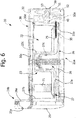
- FIG. 4 Represented in Figure 4 are only some of the components of the auxiliary device 20, for a better understanding of the invention. Also visible in said figure are the lower body 26 and, partially, the body 27 defining the tub 22 of Figure 1 . The upper component or sprinkler member 30 is moreover partially visible. From said figure it may be noted how the body 26 defines a front wall 26a that is to be coupled with the lid 25 of the movable part of structure 21b.
- Designated by 34 is a lower opening of the body 26, passing in which is a pipe 35 connected to an opening for draining the tub 22 (visible only in Figure 6 and designated by 22a), to which there can advantageously be associated a protection device - such as, for example, a filter with a rather wide mesh, designed to intercept any possible objects of large dimensions (such as coins, broaches, or buttons) and thus prevent them from entering the pipe 35.
- a protection device - such as, for example, a filter with a rather wide mesh, designed to intercept any possible objects of large dimensions (such as coins, broaches, or buttons) and thus prevent them from entering the pipe 35.
- the bottom 27a of the body 27 defining the tub 22 advantageously has a development that descends or is inclined towards the drain opening 22a in order to facilitate inflow of the washing liquid into the pipe 35 and consequently emptying of the tub 22.
- the pump 40 designated as a whole by 40 is an electric pump, of a conception in itself known, having an intake section 41 and a delivery section 42.
- the pump 40 whether centrifugal or volumetric (it may be, for example, in said latter case, a peristaltic pump, as well as a lobe pump or a diaphragm pump), is able to work overhead.
- Designated by 31 is the aforesaid first water-inlet duct, which is in fluid communication with at least one internal channel of the sprinkler member 30.
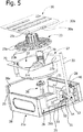
- FIG. 5 is a partially exploded view of the device 20.
- the sprinkler member 30 presents a first inlet and a second inlet, designated by 30a and 30b, which in one embodiment are connected in fluid communication with the aforesaid internal channel of the sprinkler member 30.
- the agitator member 23 the body 27 defining the washing tub 22, and the body 26 to which the body 27 is to be coupled at the top; as can be noticed, coupled to the front wall 26a of the body 26 is the front lid 25.
- Figure 5 moreover designated by 36 is an electric motor, of a type in itself known, for actuating the agitator member 23.
- the pump 40 is anchored to the fixed part 21a of the structure 21, preferably to one of the side walls 28 so as to enable inspection, after prior removal of a corresponding plug, designated by 40a in Figures 1 and 3 , during possible maintenance operations.
- the pump 40 is in a position generally behind the device 20, and preferably in a position comprised between the rear ends of the side walls 28 and the position assumed by a wall rear 26b of the body 26, when the movable part of structure 21b is in its position completely inserted in the fixed part of structure 21a.
- the auxiliary device 20 comprises a diverting device 50, which is operatively set between the delivery section 42 of the pump 40 and the drain duct 33 (it should be noted that, in Figure 4 , the drain duct 33 has not been represented for reasons of greater clarity).
- the diverting device 50 includes a hollow body having an inlet 51 that is connected in fluid communication with the delivery section 42 of the pump, via a pipe 52.
- a first outlet 53 of the hollow body of the diverter 50 is connected in fluid communication with the duct 32, designed to introduce washing liquid into the tub 22, whilst the second outlet 54 of the device 50 is connected in fluid communication with the drain duct 33 ( Figure 5 ).
- the duct 32 is connected to the inlet 30b of the sprinkler member 30, whereas the duct 31 is connected to the inlet 30a. From Figure 4 it may moreover be noted how the outlet pipe 35 of the tub 22 is connected to the intake section 41 of the pump 40.
- the diverting device 50 can be of any known type and preferably comprises an electric actuator, partially visible in Figures 4 and 6 , where it is designated by 50a, for example, a thermal actuator. Said actuator is operative for displacing a partition wall inside the hollow body of the diverter 50 in two opposite positions, in one of which the inlet 51 is in communication with the first outlet 53 and in the other is in communication with the second outlet 54.
- the diverting device 50 i.e., its actuator 50a, is driven by a control system to assume a first position and a second position, in which, respectively, washing liquid leaving the delivery section 42 of the pump 40 is directed towards the washing tub 22, through the outlet 51 and the duct 32, or else towards the drain duct 33, through the outlet 54.
- the control system is also pre-arranged for driving the diverting device 50 in order to assume the aforesaid first position in at least one washing step of a treatment cycle carried out by the auxiliary device 20, in such a way as to cause a recirculation of washing liquid in the tub 22 via the pump 40, and to assume the aforesaid second position in at least one draining step of the treatment cycle in order to cause discharge of the washing liquid from the tub 22, via the pump 40 itself.
- the amount of water that can be used for carrying out a treatment cycle can be less than in the known art, in any case guaranteeing an efficient washing action, or else, given the same amount of water used as compared to the known art, guaranteeing a better washing efficiency.
- the upper sprinkler member 30 is provided, which extends at least in part above the tub 22, and precisely above its upper opening.
- the member 30 there is at least one channel, partially visible in Figure 6 , where it is designated by 30c, provided with a plurality of nozzles or openings designated by 60 in Figure 7 (see also Figure 10 ), facing directly inside the tub 22 when the movable part of structure 21b is in its retracted position.
- the internal channel 30c of the sprinkler member 30 is connected to the inlet 30b of Figure 5 , to which the duct 32 is connected.
- the washing liquid is sprinkled in a substantially rain-like fashion on the articles to be treated contained in the tub 22, through the openings 60 of the member 30.
- the cross section of the channel 30c decreases along its development. In this way, there is obtained the possibility of maintaining the speed of the water in the channel itself substantially constant, compensating for the progressive loss of flowrate through the openings 60.
- the internal channel 30c of the sprinkler member 30 also has a second inlet, designated by 30a in Figure 5 , to which the duct 31 is connected, which is in turn in fluid communication with a water-supply source.
- the water is first fed through the duct 31, and then penetrates into the channel 30c inside the sprinkler member 30 and drops into the tub 22, via the openings 60.
- the motor 36 is actuated for setting the agitator member 23 in rotation.
- the control system brings the diverting device 50 into its first operative position and governs the pump 40, in such a way that the washing liquid will be taken in by the pump itself through the outlet 22a ( Figure 6 ) and the pipe 35 ( Figure 4 ) and then re-introduced into the tub 22 through the pipe 52, the diverter 50, the pipe 32, and the sprinkler member 30.
- the control system governs arrest of the motor 36 and switching of the diverting device 50 into the second operative position.
- the pump 40 is activated, with the washing liquid present in the tub 22 that can hence be taken in via the duct 35 connected to the intake section 41 of the pump 40, and then be directed towards the drain pipe 32.
- the tub 22 has a bottom wall and a peripheral wall (designated by 27a and 27b in Figure 6 ) and an upper opening (visible, for example, in Figure 1 ), with a portion of the sprinkler member 30 provided with openings 60 ( Figure 7 ) that overlies the upper opening of the tub 22.
- the agitator member 23 preferably has a body, the lower face of which faces directly the bottom wall of the tub 22, whilst its upper face, designed to support the articles to be treated, directly faces the aforesaid portion of the sprinkler member 30. With this arrangement the aforesaid rain-like sprinkling of the articles to be treated is guaranteed.
- the peripheral wall 27b of the tub 22, which is here substantially cylindrical, and the body of the agitator member 23 substantially delimit the volume for containment of the articles to be treated. In this way, it is not necessary to envisage a drum as in the prior art, provided with a peripheral wall.
- the body of the agitator member 23 is substantially disk-shaped, as may be seen in Figures 5 and 6 , and is rotatably mounted in the tub 22 so as to turn according to a substantially vertical axis.
- this agitator member has in its upper face a plurality of radial ribbings 23a, which contribute to favouring agitation of the articles contained in the tub 22.
- the body of the agitator member 23 is provided with a plurality of through openings 23b, through which the washing liquid can reach the inclined bottom 27b of the tub 22 and then flow out towards the corresponding structure opening 22a ( Figure 6 ).
- the body of the agitator member 23 has a hollow central relief, designated by 23c, which is rotatably mounted on a central relief 27c of the bottom wall of the tub 22.
- This type of coupling guarantees an optimal centring of the agitator member 23 with respect to the tub 22, during its rotation.
- Conveniently housed within the central relief 27c of the tub 22 is the motor 36, the stator of which is anchored at least to the body 27 and the rotor of which is connected to the agitator member 23, with interposition of adequate hydraulic seal means.
- the pump 40 is mounted on the stationary part 21a of the load-bearing structure 21 of the auxiliary device 20, whilst the body 27 defining the tub 22 is mounted on the movable part 21b, which is substantially configured as a drawer that can assume an extracted position and a retracted position.
- the pipe 35 that connects the intake section 41 of the pump 40 to the drain opening of the tub 22 can vary in configuration, during passage of the movable part 21b between the extracted and retracted positions.
- Figures 7 and 9 from which it may be noted how the pipe 35 can in effect change configuration in the two aforesaid positions that can be assumed by the movable part 21a.
- the pipe 35 can be at least in part bellows-shaped and made of an elastic material, for example an elastomer such as EPDM.
- the auxiliary device 20 can advantageously be provided with a bistable mechanical detent, of a conception in itself known. Such a device is designated by 65 in Figure 7 .
- the auxiliary device 20 is preferably provided with a sensor means, such as a microswitch, for detecting whether the movable drawer part 21b is in its completely retracted position in order to enable or inhibit electrical supply of the device 20 accordingly.
- the bearing structure 21 of the auxiliary device 20 can be configured for installation in the upper part of the cabinet 11 of the main machine 10.
- the overall structure of the device 20 can be similar to the one already illustrated and described previously.
- the body 27 defining the tub 22, and the other components associated thereto can be carried by a stationary part 21a of the structure, whilst the sprinkler member 30 belongs to the movable part 21b of the structure itself.
- the sprinkler member 30, or the body that integrates or supports it is rotatable about a substantially horizontal axis between a lowered position and a raised position, illustrated in the figures.
- the sprinkler member 30 (and the possible other movable part of structure that integrates it) is substantially configured as a top lid of the auxiliary device 20, in a way similar to a top-loading laundry washing machine.
- a gasket 30d associated to the member 30 is a gasket 30d, designed to provide tightness with respect to the body 27 when the member itself is in the lowered position (it should be noted that a similar gasket, preferably a lip gasket, is provided also in the case where the member 30 is stationary and the part 21b is configured like a drawer - see the reference 30d in Figure 6 ).
- the ducts connected to the inlets 30a and 30b of the sprinkler member 30 preferably have at least one flexible portion in order to enable the necessary angular movement of the sprinkler member 30.
- the diverting device 50 will be supported by the stationary part of the load-bearing structure of the device 20; however, not excluded is an installation thereof on the movable part.
- a microswitch or the like can be provided to detect the position of the movable part represented by the member 30 and enable or inhibit electrical supply of the device 20 accordingly.
- the auxiliary device 20 is provided with at least one dispenser of a washing agent, such as a detergent or an additive.
- the body 27 defining the tub 22 integrates at least one receptacle.
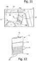
- two of said receptacles are shown, basically constituted by spaces or compartments, designated by 70 in Figures 5 , 8 and 11 , which extend in a radial direction with respect to the peripheral profile of the tub 22.
- the spaces 70 are defined directly by the body 27 at the peripheral wall 27b of the tub 22, which are open at the top and closed at the front - i.e., delimited with respect to the volume for containment of the items to be treated - by a wall 71.
- said wall 71 is configured as component distinct from the tub body and is mounted in a corresponding rectilinear guide 70a of the spaces 70 ( Figure 11 ) so that it can be removed manually by a user, for example for cleaning purposes.
- the wall 71 (visible in detail in Figure 12 ) is provided with a corresponding top gripping means or grip 72.
- the movable wall 71 then has an array of through holes or openings 73.
- a series of notches or recesses 74 is provided at at least one edge of the wall 71, in particular at its bottom edge 71a.
- the wall 71 when the wall 71 is in its normal operative position, i.e., it is inserted in the corresponding guide 70a, its bottom edge 71a is substantially set resting on a bottom wall of the notch 70 (partially visible in Figure 11 , where it is designated by 70b). Within the space 70 there can then be introduced a dose of detergent in powder or tablet form (or also a liquid washing agent, with a different shape of the wall 71), when the tub 22 is accessible.
- a dose of detergent in powder or tablet form or also a liquid washing agent, with a different shape of the wall 71
- the space 70 can be pre-arranged in such a way that its volume corresponds substantially to a recommended dose of a corresponding washing agent in bulk form, such as a detergent in powder or liquid form.
- a corresponding washing agent in bulk form
- at least one of the walls that delimit the space 70 carries, for this purpose, on a visible surface thereof, one or more level reference marks, aimed at facilitating the user in dosing the washing agent.
- the wall 71 in particular in its face that is to face the inside of the space 70, has a reference mark 71b indicating the recommended level for the washing agent (here soap powder).
- the wall 71 can also be made of transparent material so that the reference mark 71b can be provided on its surface outside the space 70.
- the internal channel 30c of the sprinkler member 30 preferably has one or more additional nozzles or openings, designated by 60a in Figures 7 and 10 , which are not positioned above the upper opening of the tub 22, but above the compartment 70 or compartments 70 provided. Thanks to these additional openings 60a, which may possibly have a diameter greater than that of the openings 60, there can be obtained a first dissolution or mixing of the washing agent in the liquid introduced. As may be appreciated, in this way, the water can reach the inside of the space 70 and mix with the detergent and/or dissolve it, with the mixture of water and washing agent that can then flow towards the inside of the tub 22 via the notches 74 and/or the holes 73.
- the sprinkler member 30 can comprise a single internal channel, belonging to which are both the openings 60 and the openings 60a, in which case a first removal of the washing agent from the space 70 is obtained during intake of water from the mains supply, via the duct 31, and a second removal is obtained when the pump 40 and the deflector member 50 operate in the liquid-recirculation mode.
- the member 30 are at least two distinct channels, one of which is fed through the inlet 30a and the other is fed through the inlet 30b.
- Such a case is exemplified in Figures 13 and 14 , where the two aforesaid channels are designated by 30c' and 30c".
- a part of the member 30 of Figure 14 is represented in see-through view in order to highlight the two aforesaid channels.
- Figures 13 and 14 highlight also a possible variant for the orientation of the inlets 30a and 30b, here set substantially orthogonal to the body of the member 30.
- the water introduced via the duct 31 flows in the channel 30c' and then comes out of the corresponding openings 60 being rain-sprinkled into the tub 22.
- the duct 32 is supplied, and then the second channel 30c", which proceeds with the rain-sprinkling of the articles to be treated.
- auxiliary openings 60a can be provided for the purposes of removal of a washing agent contained in a respective space 70.
- the channel 30c' can be provided with just the openings 60a, in such a way that the water introduced via the duct 31 into the channel 30c' can drop in a corresponding space 70 containing a washing agent, with the mixture of water and washing agent that then reaches the inside of the tub 22.
- the duct 32 is supplied, and then the channel 30c" inside the device 30, which carries out rain-like sprinkling of the articles to be treated.
- the additional openings 60a are supplied together with some of the openings 60 only during recirculation of the washing liquid.
- the water coming from the mains supply through the duct 31 then reaches the inside of the tub 22 via holes 60 of a first channel 30c' inside the sprinkler member 30, without passing through the space 70.
- This can be followed by a first step of agitation of the articles to be washed, by means of the agitator member 23 (a sort of soaking in the absence of detergent).
- the second channel 30c" inside the member 30 is supplied, which includes both openings 60 for enabling rain-sprinkling of the articles to be washed and additional openings 60a for enabling removal of the washing agent from a corresponding space 70.
- a number of doses of one and the same washing agent may be used, or else a number of different washing agents, such as a detergent and an additive (for example, a whitening agent),
- the doses or the various washing agents can be taken in at different times of the treatment program.
- a first dose or the detergent may be taken in from a first space 70 upon intake of water into the tub, via at least one opening 60a in fluid communication with a channel 30c' inside the sprinkler member 30 that is supplied via the duct 31.
- the pump 40 and the diverting member 50 are actuated in the recirculation mode, with the water that thus reaches a second channel 30c" inside the sprinkler member 30, supplied via the duct 32.
- Said second channel envisages at least one opening 60a at the second space 70, which contains the second dose of detergent or the additive, which is thus removed.
- the bottom 70b of the spaces 70 is at a level or height higher than the agitator member 30 and the bottom of the tub 22.
- the bottom 70b of a single space 70 could be set further down, or at a height lower than the minimum level of liquid normally present in the tub 22.
- no openings 60a are necessary for said space, with entry of the liquid into the compartment itself that takes place from below, through the notches 74 and the holes 73.
- Actuation of the agitator member 23, and hence agitation also of the washing bath guarantees flows entering and leaving the space 70, with removal of the detergent.
- Said second space will have the corresponding bottom 70a at a height greater than the aforesaid minimum level, to enable at a subsequent time intake of the washing agent contained therein, for example following upon starting of the recirculation step, in a way similar to the case described previously.
- the rain-like sprinkling enabled by the sprinkler member 30, albeit extremely advantageous, is not indispensable for the purposes of implementation of the invention, given that the sprinkler member could be replaced by a body defining a channel with one or more outlets 60a open only above a corresponding space 70, for intake of the washing agent.
- a channel for introducing the water into a compartment 70 could be defined or associated to the tub body.
- an electrically controllable diverter for feeding in a selective way the liquid to the tub or else to a channel for supply of a space 70, not necessarily provided in a sprinkler member of the type described above.
- the auxiliary device according to the invention can advantageously be provided with at least one dispenser, including a space or receptacle in which the user can previously introduce a desired amount of washing agent for execution of a subsequent treatment cycle.
- the aforesaid receptacle functions as flow decelerator, irrespective of whether it is fed from above or from beneath, enabling formation of the mixture of water and washing agent in a more gradual way as compared to known solutions, with a reduced risk of formation of foam.
- a number of spaces 70 it is moreover possible to obtain intake of a number of doses of one and the same washing agent, or of different washing agents, at subsequent times of one and the same treatment cycle.
- the tub 22, and hence a space 70 can belong to the movable part of structure ( Figures 3-9 ) or else to the fixed part of structure ( Figure 10 ) of the auxiliary device 20, with the channel that conveys the liquid into the space itself that is located, instead, in the fixed part or in the movable part of the structure, respectively.
- the auxiliary device 20 can envisage even more than one treatment step, each comprising delivery of the washing liquid into the tub, a step of recirculation of the washing liquid with agitation of the articles to be treated, and a final drainage step.
- steps of washing in a strict sense and rinsing steps there can thus be envisaged, for example, steps of washing in a strict sense and rinsing steps.
- the auxiliary device 20 is provided with a control circuit of its own, constituted, for example, by an electronic board designed to manage all the electrical loads of the device itself, such as the motor 36, the pump 40, the diverter device 50, and the means for heating the washing liquid that may be provided.
- These heating means can, for example, be integrated in the pump 40, according to a technology known, for example, in the sector of dish-washers, or else comprises one or more resistors in the form of films or serigraphs applied directly on the internal surface of the tub 22 (for example, on the surface of the bottom 27a of the body 27, which forms the tub), or else again envisage a cartridge heater set between the agitator member 23 and the body 27 defining the tub 22.
- the heater is designated by 75 - the body 27 has a lower area in which the heater 75 remains immersed during operation of the auxiliary device 20.
- control circuit of the auxiliary device 20 preferably also comprises a micro-switch or the like, designated by 76 in Figure 13 , designed to detect the displacement of the movable part of the structure from the retracted (or lowered) position to the extracted (or raised) position in order to interrupt supply of the aforesaid electrical loads accordingly, for obvious reasons of safety.
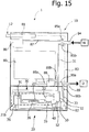
- Figure 15 illustrates one of the possible modalities of connection of the auxiliary device 20, in combination with a main machine purposely configured.
- This figure is a schematic representation of the main machine 10, with the corresponding cabinet 11, present inside which is a washing tub 80, rotatably housing a corresponding laundry drum.
- the circuit arrangement 81 supervises operation of all the electrical loads inside the main machine 10, and stored therein are the programs for management of operation of the machine itself.
- the circuit arrangement 81 of the machine 10 is also provided for interacting with a circuit arrangement 82 on board the auxiliary device 20, also in order to provide the latter with adequate electrical supply both in voltage and in current.
- circuit arrangement 82 consists, for example, of a microprocessor electronic board, which controls, as has already been said, the electrical loads inside the auxiliary device 20 (in the previous figures said control board has not been represented for simplicity; said board 82 is in any case conveniently fixed to the stationary part of the structure of the auxiliary device 20, for example on the back thereof).
- the circuit arrangements 81 and 82 are connected together by means of a communication line 83 in such a way that operation of the main machine 10 and of the auxiliary device 20 - or of at least some of the respective internal electrical loads - can be co-ordinated, as will be explained hereinafter.
- the circuit arrangements 81 and 82 are pre-arranged in such a way that the user interface 12 of the main machine 10 can be used for turning on the auxiliary device 20 and setting the cycle or cycles of treatment that can be carried out by the device itself, without the latter having to be provided with a user interface of its own.
- a dedicated interface for the auxiliary device 20 may be in any case envisaged, in variant embodiments of the invention, in which the arrangements 81 and 82 are not necessarily connected together.
- a water-supply source for example a domestic drinking-water mains
- D a sewer system
- the main machine 10 is connected to the water mains W via a supply pipe union 84, set at the end of which are two solenoid valves 85a and 85b, in parallel to each another, which can be controlled by the circuit arrangement 81 for diverting the flow of water at inlet towards a dispenser of washing agents 86 and then towards the tub 80 of the main machine 10, by means of a duct 87, or else towards the duct 31 for supply of the auxiliary device 20.
- Designated by 88 is a pump for draining the main machine 10, the intake branch 88a of which is connected to a drain opening of the tub 80.
- the delivery branch 88b of the pump 88 is, instead, connected to the first inlet of a drain pipe union 89, the second inlet of which is connected to the drain pipe 33 of the auxiliary device 20, the outlet of the pipe union 89 being, instead, connected to the sewer system D.
- set upstream of each of the inlets of the pipe union 89 is a non-return valve 90a and 90b, respectively, of a conception in itself known. It should be noted that the non-return valve 90a is not strictly necessary, when the main machine 10 is provided with a device for closing the outlet of the tub, in itself known (for example, of the type described in EP-A-238570 ).
- a user loads the items to be washed into the drum contained in the tub 80, according to modalities in themselves known and the washing agent or agents into the dispenser 96; via the user interface 12 the user chooses the washing program with the possible options associated thereto (temperature, spin-drying rate, suppression of rinses, etc.).
- the circuit arrangement 81 governs opening of the valve 85a in such a way that the tub 80 will be charged with the water coming from the mains supply W, through the duct 87 and the dispenser 86, in the desired amount (for example, detected via a pressure switch), according to modalities in themselves known, after which the valve 95a closes.
- the washing cycle of the main machine 10 proceeds with modalities in themselves known.
- the circuit arrangement 81 then governs activation of the pump 88 to evacuate the washing liquid to the sewer system D.
- the main machine 10 in the case where the user wishes to use the auxiliary device 20, also the main machine 10 must be turned on, thus providing also supply to the auxiliary device 20.
- the user can set the desired treatment cycle for the auxiliary device 20 via the user interface 12 of the main machine 10.
- the user loads the items to be treated, for example shoes, into the tub 22 of the auxiliary device 20, as well as the washing agent or agents into the dedicated space or spaces 70; the user can then close the movable drawer part 21b. Said closing is detected via the micro-switch 76 referred to previously, which thus enables electrical supply of the auxiliary device 20.
- the user can then start the treatment cycle via the user interface 12.
- This start causes, by the circuit arrangement 82 (or else by the circuit arrangement 81) opening of the valve 85b, in such a way that the water at inlet from the pipe union 84 can traverse the duct 31, and then reach the washing tub 22 of the auxiliary device 20.
- the circuit arrangement 82 causes directly or, via the circuit arrangement 81, closing of the valve 85b and subsequently governs the electrical loads of interest of the auxiliary device 20, for example the motor 36 that actuates the agitator member 23, the pump 40, and the diverter 50, so as to obtain the aforementioned recirculation of liquid through the tub 22 (in said step, also the possible heating means for the washing liquid, controlled, for example, by means of a temperature sensor, are supplied).
- the circuit arrangement 82 governs the diverting device 50 and then activation of the pump 40, which thus operates in the discharge mode to evacuate the washing liquid from the tub 22, via the ducts 35 and 33.
- the steps referred to above are carried out for each step of the treatment cycle envisaged. Intake of the washing agent or agents can take place, for example, according to one of the modalities described previously.
- the motor 36 of the auxiliary device 20 - a low power motor - is designed to produce rotation of the agitator member 23 at a relatively low speed, around 15-25 r.p.m., according to the washing program selected by the user.
- the tub 22 is preferably sized for containing an amount of articles indicatively comprised between 1.5 and 2.5 kg and the overall water consumption for a complete treatment cycle may be around 15-20 1 for a washing treatment (to which there is to be added the possible other amount necessary for the rinsing treatment).
- the washing action is obtained via a mechanical agitation of the articles to be treated, obtained via the agitator member 23 provided with its surface ribbings 23a, with the concomitant rain-like sprinkling provided via the sprinkler member 30 and the pump 40.
- the member designed to carry out sprinkling of the washing liquid on the articles contained in the tub 22 can be of a rotary type, i.e., of a conception substantially resembling that of sprinkler members provided on dish-washers.
- a rotary type i.e., of a conception substantially resembling that of sprinkler members provided on dish-washers.
- an upper wall will be provided, fixed or hinged, rotatably associated to which is the aforesaid rotary sprinkler; at least one internal channel of the latter will be in fluid communication with the ducts previously designated by 31 and 32.
- one or more nozzles of the rotary sprinkler may be positioned and/or oriented in such a way that, during rotation of the sprinkler, the corresponding outlet jet reaches the inside of a corresponding space 70.
- a valve that carries out the functions of the valve previously designated by 85b can be provided along the duct 31, with the latter that can be directly connected to a water-supply source W, and with the drain duct 33 that can be directly connected to the sewer system D.
- the liquid that is to feed the auxiliary device 20 does not come directly from the mains supply W, but is a liquid already used on the main machine 10, such as, for example, the water used for carrying out the last rinsing step envisaged in a treatment cycle carried out by the main machine 10.
- the water via which a washing or rinsing treatment has been carried out in the auxiliary device 20 could be stored in a tank, instead of being discharged, so that it can be reused in a subsequent washing treatment in the main machine 10 or in the auxiliary device 20.
- the space 70 is designed for containment of a washing agent in powder or tablet form, but, as has been said, said compartment can be used for loading a liquid washing agent, such as a liquid detergent or a bleaching agent.
- a liquid washing agent such as a liquid detergent or a bleaching agent.
- the wall 71 could be mounted fixed in a fluid-tight way, or else provided with a gasket designed to provide fluid-tightness with respect to the corresponding seat 70a.
- the wall 71 may be without the holes 73 and the notches 74, envisaging, instead, in its lower part, a single outlet provided with siphon that gives out into the tub 22 in such a way that dispensing of the washing agent will take place when a certain level of liquid is reached in the space 70.
- an overflow dispensing mode i.e., with a series of holes 73 provided in an intermediate area of the wall in such a way that the mixture constituted by water and washing agent can overflow into the tub 22 when the mixture itself in the space 70 exceeds the level corresponding to the aforesaid holes.
- Another possibility is to associate removably to the space 70 a basin designed for containment of the liquid washing agent, also functioning as a dosing implement, provided at the bottom with the outlet opening equipped with siphon.
Description
- The present invention relates to an appliance for treating textile items, which includes:
- a main machine for treating textile items, such as a laundry washing machine, a laundry washer-drier, or a laundry drier, the main machine having a cabinet; and
- an auxiliary washing device, having a load-bearing structure provided for being fastened to the cabinet of the main machine, the load-bearing structure of the auxiliary device having a volume and a height that are, respectively, smaller than a volume and a height of the cabinet of the main machine.
- The invention moreover regards an auxiliary washing device of the type referred to above.
- Appliances of the type referred to above are known and typically consist of a main washing machine, associated to the cabinet of which is a lower base, functionally integrated in which is the auxiliary washing device.
- The main machine of the appliance is basically provided for carrying out normal treatment on more or less bulks loads of traditional textile items, such as garments, linenware, curtains, etc. The auxiliary device is generally used for washing articles that require a particular treatment, and possibly for washing amounts of traditional textile items that are so modest as not to justify - from the standpoint of water and energy consumption - execution of a complete cycle of treatment on the main machine.
- The load-bearing structure of the auxiliary device, which has overall dimensions decidedly smaller than those of the main machine, typically comprises a stationary part, fastened underneath the cabinet of the main machine, and a movable part, constituted by a drawer. Defined in said drawer is a cylindrical washing tub, open at the top, rotatably mounted within which is an agitator member, constituted by a cylindrical drum, which is also open at the top. With a configuration of the above sort, by extracting the movable drawer part from the stationary part, it is possible to gain access to the tub, and hence to the inside of the drum, for loading and unloading the articles to be treated.
- In order to carry out a cycle of treatment on the auxiliary device, a flow of water is fed into the corresponding tub, until a certain level is reached so that the drum, and hence the articles to be treated contained therein, are at least partially immersed in the washing bath; the drum is then set in rotation via an electric motor. At the end of the treatment, a discharge pump is activated in order to evacuate, via a discharge pipe, the liquid used for washing.
- An appliance substantially of the type referred to above is known, for example, from the document
US 2010/0064736 A1 . - In the appliances according to the known art the auxiliary washing device often presents a poor efficiency, both in terms of quality of treatment and in terms of use of resources such as water and electric power. In accordance with a first aspect, the present invention is basically aimed at overcoming the aforesaid drawback, and in particular to provide an appliance of the type referred to above whose auxiliary device, though being simple to produce and easy to use, ensures improved treatment results, with modest levels of consumption of water and power.
- Additionally, in auxiliary devices according to the prior art the user has to pour the possible washing agent, for example a powder detergent, directly on the items to be treated that are inside the cylindrical agitator mounted in the tub. Next, as has been said, after starting of an operating program of the device, the water necessary for washing is then loaded directly into the tub, and the movement of the agitator is started. This type of operation frequently causes an excessive formation of foam and a non-efficient exploitation of the detergent. In accordance with a second aspect, the present invention is aimed at overcoming the aforesaid drawback, by means of an auxiliary device that is simple to produce and easy to use. This aim is achieved by an auxiliary washing device having the characteristics referred to in claims 1-12 and by an appliance for treating textile as per claim 13.
- The claims form an integral part of the technical teaching provided herein in relation to the invention.
- Further purposes, characteristics, and advantages of the invention will emerge clearly from the ensuing detailed description, with reference to the annexed drawings, which are provided purely by way of explanatory and nonlimiting example and in which:
-
Figure 1 is a perspective view of an appliance for treating textile items according to the invention; -
Figure 2 is a side elevation of the appliance ofFigure 1 ; -
Figure 3 is a perspective view of an example of auxiliary washing device of an appliance according to the invention; -
Figure 4 is a perspective view of the device ofFigure 3 , with some parts removed; -
Figure 5 is a partially exploded view of the device ofFigures 3 and 4 ; -
Figure 6 is a schematic cross section of the device ofFigures 3 and 4 , with some parts removed; -
Figures 7 and 8 are a perspective view from beneath and a top plan view of the device ofFigures 3-6 , in a first condition; -
Figure 9 is a perspective view from beneath of the device ofFigures 3-6 , in a second condition; -
Figure 10 is a partial perspective view of an auxiliary washing device according to a variant of the invention; -
Figure 11 is a partial perspective view, at an enlarged scale, of an auxiliary washing device according to a particularly advantageous embodiment of the invention; -
Figure 12 is a perspective view of a component of the device ofFigure 11 ; -
Figures 13 and 14 are perspective views of a sprinkler member of an auxiliary washing device according to a variant of the invention; and -
Figure 15 is a simplified block diagram of a possible connection layout of an appliance according to the invention. - Reference to "an embodiment" or "one embodiment" in the framework of the present description is meant to indicate that a particular configuration, structure, or characteristic described in relation to the embodiment is comprised in at least one embodiment. Hence, phrases such as "in an embodiment", "in one embodiment", and the like, that may be present in various points of the present description do not necessarily all refer to one and the same embodiment. Moreover, the particular configurations, structures, or characteristics can be combined in any adequate way in one or more embodiments. The references used in what follows are only provided for convenience and do not define the sphere of protection or the scope of the embodiments.
- It is moreover pointed out that in the sequel of the present description only the elements useful for an understanding of the invention will be described, taking for granted, for example, that the main machine forming part of the appliance according to the invention comprises all the elements in themselves known for operation of a laundry washing machine, or a laundry washer-drier, or a laundry drier.
- In
Figures 1 and2 , designated as a whole by 1 is an appliance for treating textile items according to the invention. Theappliance 1 comprises amain machine 10, designed for treatment of textile items, which may be a laundry washing machine, a laundry drier, or a laundry washing and drying machine. By way of example, in the sequel of the present description it is assumed that themain machine 10 is a laundry washing machine. Themachine 10 is of a generally known construction, apart from the aspects that will be described hereinafter in relation to a possible embodiment of the invention, illustrated inFigure 15 . Consequently, it is assumed in what follows that themachine 10 includes all the elements normally known for operation of a laundry washing machine. In the example shown, themachine 10 has a generallyparallelepipedal cabinet 11, elastically suspended inside which is a washing tub that houses a laundry drum, rotatable about a horizontal axis. Themachine 10 then includes a series of usual electrical loads (motor, pumps, solenoid valves, etc.) and corresponding control means, preferably including a microcontroller electronic control board. - The aforesaid control means of the
machine 10 include a user interface, designated by 12, comprising known selection means (such as keys, pushbuttons, selectors, etc.) and adisplay device 12a, for example, of an LCD type. In the example of embodiment shown, in which themachine 10 is a front-loading machine, theaforesaid user interface 12 is integrated in the upper part of afront door 11a of thecabinet 11. - The
appliance 1 moreover includes an auxiliary washing device, designated as a whole by 20. Theauxiliary device 20 has abearing structure 21 of its own, which is provided for being fastened to thecabinet 11 of themain machine 10. In the example shown, thestructure 21 is fastened to thecabinet 11 in a lower position of the latter, to form a sort of base or pedestal. As will be seen hereinafter, however, thestructure 21 of thedevice 20 according to the invention can also be conceived for installation in the upper part of thecabinet 11, for example on its top, designated by 11b, or in substitution thereof. For the aforesaid reasons, thebearing structure 21 of theauxiliary device 20 has a volume and a height that are decidedly smaller than the volume and the height of thecabinet 11 of the main machine to which the device itself must be combined. In general terms, with reference toFigure 2 , the height A of thecabinet 11 of themachine 10 may be approximately 830 mm, whilst the height B of thestructure 21 of thedevice 20 may be approximately 215 mm; more in general, the height B may be less than half of the height A of thecabinet 11, preferably less than approximately one third of the height A. - The
bearing structure 21 of thedevice 20 includes apart 21a that is stationary with respect to thecabinet 11 of themachine 10, as well as apart 21b that is movable or displaceable with respect to thestationary part 21a in order to enable access to awashing tub 22, mounted within which in a movable way is anagitator member 23, used for moving articles to be treated in theauxiliary device 20. In the case exemplified, themovable part 21b of the structure is substantially configured like a drawer and comprises aframework 24, preferably made of metal, with afront lid 25 provided with agripping recess 25a or some other type of grip. Fixed on theframework 24 are abottom housing body 26, which is generally hollow and open upwards, coupled at the top to which is asecond body 27 defining thewashing tub 22. Thebodies movable part 21b and thestationary part 21a of thestructure 21 are, of course, guide means (not indicated), aimed at enabling sliding of the movable part with respect to the stationary part, between an extracted position and a retracted position. Thestationary part 21a basically consists of twoside walls 28 and a series of cross members, preferably constituted by metal sectional elements, some of which (not indicated) are visible in the subsequent figures. - The
auxiliary device 20 is visible in greater detail inFigures 3-6 . Visible inFigure 3 are, in addition to the twoside walls 28, also an upper component of thestationary part 21a, designated as a whole by 30, which in a preferred embodiment fulfils functions of sprinkler member. Once again inFigure 3 , designated by 31 and 32 are a first duct and a second duct for inlet of a washing liquid into the tub, while designated by 33 is a drain duct. - Represented in
Figure 4 are only some of the components of theauxiliary device 20, for a better understanding of the invention. Also visible in said figure are thelower body 26 and, partially, thebody 27 defining thetub 22 ofFigure 1 . The upper component orsprinkler member 30 is moreover partially visible. From said figure it may be noted how thebody 26 defines afront wall 26a that is to be coupled with thelid 25 of the movable part ofstructure 21b. - Designated by 34 is a lower opening of the
body 26, passing in which is apipe 35 connected to an opening for draining the tub 22 (visible only inFigure 6 and designated by 22a), to which there can advantageously be associated a protection device - such as, for example, a filter with a rather wide mesh, designed to intercept any possible objects of large dimensions (such as coins, broaches, or buttons) and thus prevent them from entering thepipe 35. As may be appreciated in particular fromFigure 6 , the bottom 27a of thebody 27 defining thetub 22 advantageously has a development that descends or is inclined towards thedrain opening 22a in order to facilitate inflow of the washing liquid into thepipe 35 and consequently emptying of thetub 22. - With particular reference once again to
Figure 4 , designated as a whole by 40 is an electric pump, of a conception in itself known, having anintake section 41 and adelivery section 42. For a suitable application, within theauxiliary device 20 according to the present invention, thepump 40, whether centrifugal or volumetric (it may be, for example, in said latter case, a peristaltic pump, as well as a lobe pump or a diaphragm pump), is able to work overhead. Designated by 31 is the aforesaid first water-inlet duct, which is in fluid communication with at least one internal channel of thesprinkler member 30. - The aforementioned components are visible also in
Figure 5 , which is a partially exploded view of thedevice 20. In said figure, it may be noted how thesprinkler member 30 presents a first inlet and a second inlet, designated by 30a and 30b, which in one embodiment are connected in fluid communication with the aforesaid internal channel of thesprinkler member 30. There may be clearly seen theagitator member 23, thebody 27 defining thewashing tub 22, and thebody 26 to which thebody 27 is to be coupled at the top; as can be noticed, coupled to thefront wall 26a of thebody 26 is thefront lid 25. InFigure 5 moreover designated by 36 is an electric motor, of a type in itself known, for actuating theagitator member 23. - The
pump 40 is anchored to thefixed part 21a of thestructure 21, preferably to one of theside walls 28 so as to enable inspection, after prior removal of a corresponding plug, designated by 40a inFigures 1 and3 , during possible maintenance operations. As may be noted, in a preferred embodiment, thepump 40 is in a position generally behind thedevice 20, and preferably in a position comprised between the rear ends of theside walls 28 and the position assumed by a wall rear 26b of thebody 26, when the movable part ofstructure 21b is in its position completely inserted in the fixed part ofstructure 21a. - With particular reference to
Figures 4 and5 , theauxiliary device 20 comprises a divertingdevice 50, which is operatively set between thedelivery section 42 of thepump 40 and the drain duct 33 (it should be noted that, inFigure 4 , thedrain duct 33 has not been represented for reasons of greater clarity). The divertingdevice 50 includes a hollow body having aninlet 51 that is connected in fluid communication with thedelivery section 42 of the pump, via apipe 52. Afirst outlet 53 of the hollow body of thediverter 50 is connected in fluid communication with theduct 32, designed to introduce washing liquid into thetub 22, whilst thesecond outlet 54 of thedevice 50 is connected in fluid communication with the drain duct 33 (Figure 5 ). In the preferred version of the invention, theduct 32 is connected to theinlet 30b of thesprinkler member 30, whereas theduct 31 is connected to theinlet 30a. FromFigure 4 it may moreover be noted how theoutlet pipe 35 of thetub 22 is connected to theintake section 41 of thepump 40. - The diverting
device 50 can be of any known type and preferably comprises an electric actuator, partially visible inFigures 4 and6 , where it is designated by 50a, for example, a thermal actuator. Said actuator is operative for displacing a partition wall inside the hollow body of thediverter 50 in two opposite positions, in one of which theinlet 51 is in communication with thefirst outlet 53 and in the other is in communication with thesecond outlet 54. - Advantageously, the diverting
device 50, i.e., itsactuator 50a, is driven by a control system to assume a first position and a second position, in which, respectively, washing liquid leaving thedelivery section 42 of thepump 40 is directed towards the washingtub 22, through theoutlet 51 and theduct 32, or else towards thedrain duct 33, through theoutlet 54. The control system is also pre-arranged for driving the divertingdevice 50 in order to assume the aforesaid first position in at least one washing step of a treatment cycle carried out by theauxiliary device 20, in such a way as to cause a recirculation of washing liquid in thetub 22 via thepump 40, and to assume the aforesaid second position in at least one draining step of the treatment cycle in order to cause discharge of the washing liquid from thetub 22, via thepump 40 itself. - Thanks to these characteristics, it is possible to obtain a recirculation of the washing liquid through the
tub 22 during a step of washing or rinsing of the articles treated in theauxiliary device 20. In this way, the amount of water that can be used for carrying out a treatment cycle can be less than in the known art, in any case guaranteeing an efficient washing action, or else, given the same amount of water used as compared to the known art, guaranteeing a better washing efficiency. - As has been seen previously, in a particularly advantageous embodiment of the invention, the
upper sprinkler member 30 is provided, which extends at least in part above thetub 22, and precisely above its upper opening. Within the body defining themember 30 there is at least one channel, partially visible inFigure 6 , where it is designated by 30c, provided with a plurality of nozzles or openings designated by 60 inFigure 7 (see alsoFigure 10 ), facing directly inside thetub 22 when the movable part ofstructure 21b is in its retracted position. As has been said, theinternal channel 30c of thesprinkler member 30 is connected to theinlet 30b ofFigure 5 , to which theduct 32 is connected. In this way, when thepump 40 is active and the divertingdevice 50 is in the aforesaid first recirculation position, the washing liquid is sprinkled in a substantially rain-like fashion on the articles to be treated contained in thetub 22, through theopenings 60 of themember 30. Advantageously, and as is clearly visible inFigure 6 , the cross section of thechannel 30c decreases along its development. In this way, there is obtained the possibility of maintaining the speed of the water in the channel itself substantially constant, compensating for the progressive loss of flowrate through theopenings 60. - In this way, the treatment is improved, thanks to the combined action of rain-like sprinkling of the washing liquid on the articles to be treated and the movement of the latter performed by the
agitator member 23. This characteristic further enhances the washing quality, even with contained amounts of liquid. - In the preferred embodiment, the
internal channel 30c of thesprinkler member 30 also has a second inlet, designated by 30a inFigure 5 , to which theduct 31 is connected, which is in turn in fluid communication with a water-supply source. - Consequently, in a preferred embodiment, for the purposes of carrying out a treatment cycle by the
auxiliary device 20, the water is first fed through theduct 31, and then penetrates into thechannel 30c inside thesprinkler member 30 and drops into thetub 22, via theopenings 60. When a given amount of water has been introduced into the tub (for example, detected via a flowmeter or a pressure switch), themotor 36 is actuated for setting theagitator member 23 in rotation. The control system brings the divertingdevice 50 into its first operative position and governs thepump 40, in such a way that the washing liquid will be taken in by the pump itself through theoutlet 22a (Figure 6 ) and the pipe 35 (Figure 4 ) and then re-introduced into thetub 22 through thepipe 52, thediverter 50, thepipe 32, and thesprinkler member 30. - At the end of the treatment step, the control system governs arrest of the
motor 36 and switching of the divertingdevice 50 into the second operative position. Next, thepump 40 is activated, with the washing liquid present in thetub 22 that can hence be taken in via theduct 35 connected to theintake section 41 of thepump 40, and then be directed towards thedrain pipe 32. - In the embodiment currently deemed preferred, the
tub 22 has a bottom wall and a peripheral wall (designated by 27a and 27b inFigure 6 ) and an upper opening (visible, for example, inFigure 1 ), with a portion of thesprinkler member 30 provided with openings 60 (Figure 7 ) that overlies the upper opening of thetub 22. As may be seen inFigure 6 , theagitator member 23 preferably has a body, the lower face of which faces directly the bottom wall of thetub 22, whilst its upper face, designed to support the articles to be treated, directly faces the aforesaid portion of thesprinkler member 30. With this arrangement the aforesaid rain-like sprinkling of the articles to be treated is guaranteed. As may be appreciated, in the embodiment in question, theperipheral wall 27b of thetub 22, which is here substantially cylindrical, and the body of theagitator member 23 substantially delimit the volume for containment of the articles to be treated. In this way, it is not necessary to envisage a drum as in the prior art, provided with a peripheral wall. - Preferably, the body of the
agitator member 23 is substantially disk-shaped, as may be seen inFigures 5 and6 , and is rotatably mounted in thetub 22 so as to turn according to a substantially vertical axis. FromFigure 5 it may be noted how this agitator member has in its upper face a plurality ofradial ribbings 23a, which contribute to favouring agitation of the articles contained in thetub 22. From this figure, it may moreover be noted how the body of theagitator member 23 is provided with a plurality of throughopenings 23b, through which the washing liquid can reach theinclined bottom 27b of thetub 22 and then flow out towards the corresponding darin opening 22a (Figure 6 ). - In the preferred embodiment represented, the body of the
agitator member 23 has a hollow central relief, designated by 23c, which is rotatably mounted on acentral relief 27c of the bottom wall of thetub 22. This type of coupling guarantees an optimal centring of theagitator member 23 with respect to thetub 22, during its rotation. For this purpose there can be used rolling or sliding guide means between the two parts in question. Conveniently housed within thecentral relief 27c of thetub 22 is themotor 36, the stator of which is anchored at least to thebody 27 and the rotor of which is connected to theagitator member 23, with interposition of adequate hydraulic seal means. - In the embodiment exemplified in the figures, the
pump 40 is mounted on thestationary part 21a of the load-bearing structure 21 of theauxiliary device 20, whilst thebody 27 defining thetub 22 is mounted on themovable part 21b, which is substantially configured as a drawer that can assume an extracted position and a retracted position. For this reason, thepipe 35 that connects theintake section 41 of thepump 40 to the drain opening of thetub 22 can vary in configuration, during passage of themovable part 21b between the extracted and retracted positions. The idea may be clearly seen inFigures 7 and9 , from which it may be noted how thepipe 35 can in effect change configuration in the two aforesaid positions that can be assumed by themovable part 21a. For this purpose, for example, thepipe 35 can be at least in part bellows-shaped and made of an elastic material, for example an elastomer such as EPDM. To enable the drawer part to remain stably in the retracted position, even in the presence of vibrations generated by themain machine 10, theauxiliary device 20 can advantageously be provided with a bistable mechanical detent, of a conception in itself known. Such a device is designated by 65 inFigure 7 . In addition, theauxiliary device 20 is preferably provided with a sensor means, such as a microswitch, for detecting whether themovable drawer part 21b is in its completely retracted position in order to enable or inhibit electrical supply of thedevice 20 accordingly. - As mentioned previously, according to a possible embodiment of the invention, the bearing
structure 21 of theauxiliary device 20 can be configured for installation in the upper part of thecabinet 11 of themain machine 10. In such an embodiment, the overall structure of thedevice 20 can be similar to the one already illustrated and described previously. In a possible variant, however, thebody 27 defining thetub 22, and the other components associated thereto, can be carried by astationary part 21a of the structure, whilst thesprinkler member 30 belongs to themovable part 21b of the structure itself. - Such a case is exemplified in
Figure 10 . According to said variant, thesprinkler member 30, or the body that integrates or supports it, is rotatable about a substantially horizontal axis between a lowered position and a raised position, illustrated in the figures. In this way, the sprinkler member 30 (and the possible other movable part of structure that integrates it) is substantially configured as a top lid of theauxiliary device 20, in a way similar to a top-loading laundry washing machine. In this way, in order to gain access to the inside of thetub 22, it is sufficient to raise the movable part ofstructure 21b integrating thesprinkler member 30, which will be able to rotate about the aforesaid substantially horizontal axis that preferably extends in a rear area of the structure of the device. For said purpose known hinges can be used. Preferably, associated to themember 30 is agasket 30d, designed to provide tightness with respect to thebody 27 when the member itself is in the lowered position (it should be noted that a similar gasket, preferably a lip gasket, is provided also in the case where themember 30 is stationary and thepart 21b is configured like a drawer - see thereference 30d inFigure 6 ). In an embodiment of the type illustrated inFigure 10 , the ducts connected to theinlets sprinkler member 30 preferably have at least one flexible portion in order to enable the necessary angular movement of thesprinkler member 30. In this application, as in the one illustrated previously, the divertingdevice 50 will be supported by the stationary part of the load-bearing structure of thedevice 20; however, not excluded is an installation thereof on the movable part. Also in this case, a microswitch or the like can be provided to detect the position of the movable part represented by themember 30 and enable or inhibit electrical supply of thedevice 20 accordingly. - In accordance with the inventive concept, the
auxiliary device 20 is provided with at least one dispenser of a washing agent, such as a detergent or an additive. In the preferred embodiment, for this purpose, thebody 27 defining thetub 22 integrates at least one receptacle. In the figures two of said receptacles are shown, basically constituted by spaces or compartments, designated by 70 inFigures 5 ,8 and11 , which extend in a radial direction with respect to the peripheral profile of thetub 22. In the preferred example, thespaces 70 are defined directly by thebody 27 at theperipheral wall 27b of thetub 22, which are open at the top and closed at the front - i.e., delimited with respect to the volume for containment of the items to be treated - by awall 71. In a preferred embodiment, saidwall 71 is configured as component distinct from the tub body and is mounted in a correspondingrectilinear guide 70a of the spaces 70 (Figure 11 ) so that it can be removed manually by a user, for example for cleaning purposes. For this purpose, preferably, the wall 71 (visible in detail inFigure 12 ) is provided with a corresponding top gripping means orgrip 72. Themovable wall 71 then has an array of through holes oropenings 73. Preferably, provided at at least one edge of thewall 71, in particular at itsbottom edge 71a, is a series of notches or recesses 74. As may be appreciated, when thewall 71 is in its normal operative position, i.e., it is inserted in thecorresponding guide 70a, itsbottom edge 71a is substantially set resting on a bottom wall of the notch 70 (partially visible inFigure 11 , where it is designated by 70b). Within thespace 70 there can then be introduced a dose of detergent in powder or tablet form (or also a liquid washing agent, with a different shape of the wall 71), when thetub 22 is accessible. - Very advantageously, the
space 70, or eachspace 70, can be pre-arranged in such a way that its volume corresponds substantially to a recommended dose of a corresponding washing agent in bulk form, such as a detergent in powder or liquid form. In a variant, at least one of the walls that delimit thespace 70 carries, for this purpose, on a visible surface thereof, one or more level reference marks, aimed at facilitating the user in dosing the washing agent. Such a case is also exemplified inFigure 12 , where thewall 71, in particular in its face that is to face the inside of thespace 70, has areference mark 71b indicating the recommended level for the washing agent (here soap powder). Of course, thewall 71 can also be made of transparent material so that thereference mark 71b can be provided on its surface outside thespace 70. - In the embodiment exemplified in the figures, the
internal channel 30c of thesprinkler member 30 preferably has one or more additional nozzles or openings, designated by 60a inFigures 7 and10 , which are not positioned above the upper opening of thetub 22, but above thecompartment 70 orcompartments 70 provided. Thanks to theseadditional openings 60a, which may possibly have a diameter greater than that of theopenings 60, there can be obtained a first dissolution or mixing of the washing agent in the liquid introduced. As may be appreciated, in this way, the water can reach the inside of thespace 70 and mix with the detergent and/or dissolve it, with the mixture of water and washing agent that can then flow towards the inside of thetub 22 via thenotches 74 and/or theholes 73. - The
sprinkler member 30 can comprise a single internal channel, belonging to which are both theopenings 60 and theopenings 60a, in which case a first removal of the washing agent from thespace 70 is obtained during intake of water from the mains supply, via theduct 31, and a second removal is obtained when thepump 40 and thedeflector member 50 operate in the liquid-recirculation mode. - In another possible embodiment, provided within the
member 30 are at least two distinct channels, one of which is fed through theinlet 30a and the other is fed through theinlet 30b. Such a case is exemplified inFigures 13 and 14 , where the two aforesaid channels are designated by 30c' and 30c". It is to be noted that a part of themember 30 ofFigure 14 is represented in see-through view in order to highlight the two aforesaid channels. It should be moreover noted thatFigures 13 and 14 highlight also a possible variant for the orientation of theinlets member 30. - According to the embodiment of
Figures 13 and 14 , the water introduced via theduct 31 flows in thechannel 30c' and then comes out of the correspondingopenings 60 being rain-sprinkled into thetub 22. Next, in the course of washing, with the arrangement constituted by thepump 40 and the divertingdevice 50 active in recirculation mode, theduct 32 is supplied, and then thesecond channel 30c", which proceeds with the rain-sprinkling of the articles to be treated. Obviously, also in this case,auxiliary openings 60a can be provided for the purposes of removal of a washing agent contained in arespective space 70. - It is also clear that, for example, the
channel 30c' can be provided with just theopenings 60a, in such a way that the water introduced via theduct 31 into thechannel 30c' can drop in acorresponding space 70 containing a washing agent, with the mixture of water and washing agent that then reaches the inside of thetub 22. Next, during washing, with the arrangement constituted by thepump 40 and thedeflector member 50 active in recirculation mode, theduct 32 is supplied, and then thechannel 30c" inside thedevice 30, which carries out rain-like sprinkling of the articles to be treated. - Not to be excluded is, however, a different arrangement, whereby the
additional openings 60a are supplied together with some of theopenings 60 only during recirculation of the washing liquid. In such an embodiment, the water coming from the mains supply through theduct 31 then reaches the inside of thetub 22 viaholes 60 of afirst channel 30c' inside thesprinkler member 30, without passing through thespace 70. This can be followed by a first step of agitation of the articles to be washed, by means of the agitator member 23 (a sort of soaking in the absence of detergent). Next, when thepump 40 is actuated in recirculation mode, thesecond channel 30c" inside themember 30 is supplied, which includes bothopenings 60 for enabling rain-sprinkling of the articles to be washed andadditional openings 60a for enabling removal of the washing agent from a correspondingspace 70. - In the case of a number of
spaces 70, as illustrated, a number of doses of one and the same washing agent may be used, or else a number of different washing agents, such as a detergent and an additive (for example, a whitening agent), Advantageously, the doses or the various washing agents can be taken in at different times of the treatment program. For example, a first dose or the detergent may be taken in from afirst space 70 upon intake of water into the tub, via at least oneopening 60a in fluid communication with achannel 30c' inside thesprinkler member 30 that is supplied via theduct 31. After carrying out a first treatment step, in the absence of operation of the pump in recirculation mode, the liquid is evacuated from thetub 22 and a the tub is once again charged with water. Once this operation is completed, thepump 40 and the divertingmember 50 are actuated in the recirculation mode, with the water that thus reaches asecond channel 30c" inside thesprinkler member 30, supplied via theduct 32. Said second channel envisages at least oneopening 60a at thesecond space 70, which contains the second dose of detergent or the additive, which is thus removed. - It is likewise clear that, according to other possible embodiments, there may be provided purposely designed electrically controllable diverters, for supplying selectively a number of channels inside the sprinkler member 30 (and hence also a number of spaces 70), both in the case of water coming from the
duct 31 and in the case of water coming from theduct 32. - In the example of embodiment illustrated, the bottom 70b of the
spaces 70 is at a level or height higher than theagitator member 30 and the bottom of thetub 22. In an alternative embodiment, however, the bottom 70b of asingle space 70 could be set further down, or at a height lower than the minimum level of liquid normally present in thetub 22. In such an embodiment noopenings 60a are necessary for said space, with entry of the liquid into the compartment itself that takes place from below, through thenotches 74 and theholes 73. Actuation of theagitator member 23, and hence agitation also of the washing bath guarantees flows entering and leaving thespace 70, with removal of the detergent. Also in such an embodiment, there may in any case be provided a second space, for a second dose of the detergent or of a different washing agent. Said second space will have thecorresponding bottom 70a at a height greater than the aforesaid minimum level, to enable at a subsequent time intake of the washing agent contained therein, for example following upon starting of the recirculation step, in a way similar to the case described previously. - It should also be pointed out that the recirculation arrangement illustrated in the figures, including the diverting
member 50 that enables exploitation of thedrain pump 40 also during washing, is not strictly indispensable for the purposes of implementation of the aforesaid inventive concept. As has already been mentioned, in fact, removal of the washing agent from aspace 70 can be obtained by means of a channel inside thesprinkler member 30 fed by the water source, and hence without any need for a recirculation arrangement, which could thus be omitted. It will moreover be appreciated that the rain-like sprinkling enabled by thesprinkler member 30, albeit extremely advantageous, is not indispensable for the purposes of implementation of the invention, given that the sprinkler member could be replaced by a body defining a channel with one ormore outlets 60a open only above a correspondingspace 70, for intake of the washing agent. Once again, a channel for introducing the water into acompartment 70 could be defined or associated to the tub body. - According to other possible embodiments, there can also be provided an electrically controllable diverter for feeding in a selective way the liquid to the tub or else to a channel for supply of a
space 70, not necessarily provided in a sprinkler member of the type described above. - Consequently, as may be noted, the auxiliary device according to the invention can advantageously be provided with at least one dispenser, including a space or receptacle in which the user can previously introduce a desired amount of washing agent for execution of a subsequent treatment cycle. This prevents the user having to pour the washing agent directly into the
tub 22 of the auxiliary device, between the items to be treated. The aforesaid receptacle functions as flow decelerator, irrespective of whether it is fed from above or from beneath, enabling formation of the mixture of water and washing agent in a more gradual way as compared to known solutions, with a reduced risk of formation of foam. In the embodiments in which a number ofspaces 70 are provided, it is moreover possible to obtain intake of a number of doses of one and the same washing agent, or of different washing agents, at subsequent times of one and the same treatment cycle. - It should once again be noted how, in various examples described above, removal of the detergent takes place by supplying a
space 70 from above, with the liquid that covers a path in air before reaching the inside of the compartment itself. Said measure prevents risks of reflux of the mixture constituted by the liquid and the washing agent in thesprinkler member 30 or other supply channel of thespace 70. For this purpose, as has been seen previously, thetub 22, and hence aspace 70, can belong to the movable part of structure (Figures 3-9 ) or else to the fixed part of structure (Figure 10 ) of theauxiliary device 20, with the channel that conveys the liquid into the space itself that is located, instead, in the fixed part or in the movable part of the structure, respectively. - The
auxiliary device 20 according to the invention can envisage even more than one treatment step, each comprising delivery of the washing liquid into the tub, a step of recirculation of the washing liquid with agitation of the articles to be treated, and a final drainage step. In this perspective, there can thus be envisaged, for example, steps of washing in a strict sense and rinsing steps. - In one embodiment, the
auxiliary device 20 is provided with a control circuit of its own, constituted, for example, by an electronic board designed to manage all the electrical loads of the device itself, such as themotor 36, thepump 40, thediverter device 50, and the means for heating the washing liquid that may be provided. These heating means can, for example, be integrated in thepump 40, according to a technology known, for example, in the sector of dish-washers, or else comprises one or more resistors in the form of films or serigraphs applied directly on the internal surface of the tub 22 (for example, on the surface of the bottom 27a of thebody 27, which forms the tub), or else again envisage a cartridge heater set between theagitator member 23 and thebody 27 defining thetub 22. In this case - represented schematically inFigure 6 , where the heater is designated by 75 - thebody 27 has a lower area in which theheater 75 remains immersed during operation of theauxiliary device 20. - As has been said, the control circuit of the
auxiliary device 20 preferably also comprises a micro-switch or the like, designated by 76 inFigure 13 , designed to detect the displacement of the movable part of the structure from the retracted (or lowered) position to the extracted (or raised) position in order to interrupt supply of the aforesaid electrical loads accordingly, for obvious reasons of safety. -
Figure 15 illustrates one of the possible modalities of connection of theauxiliary device 20, in combination with a main machine purposely configured. This figure is a schematic representation of themain machine 10, with thecorresponding cabinet 11, present inside which is awashing tub 80, rotatably housing a corresponding laundry drum. - In the figure, designated by 81 is a control-circuit arrangement of the
main machine 10, belonging to which is theuser interface 12. Thecircuit arrangement 81 supervises operation of all the electrical loads inside themain machine 10, and stored therein are the programs for management of operation of the machine itself. In a preferential embodiment, such as the one illustrated inFigure 15 , thecircuit arrangement 81 of themachine 10 is also provided for interacting with a circuit arrangement 82 on board theauxiliary device 20, also in order to provide the latter with adequate electrical supply both in voltage and in current. Also the circuit arrangement 82 consists, for example, of a microprocessor electronic board, which controls, as has already been said, the electrical loads inside the auxiliary device 20 (in the previous figures said control board has not been represented for simplicity; said board 82 is in any case conveniently fixed to the stationary part of the structure of theauxiliary device 20, for example on the back thereof). - In the embodiment exemplified in
Figure 15 , thecircuit arrangements 81 and 82 are connected together by means of acommunication line 83 in such a way that operation of themain machine 10 and of the auxiliary device 20 - or of at least some of the respective internal electrical loads - can be co-ordinated, as will be explained hereinafter. In a particularly advantageous embodiment, such as the one illustrated, thecircuit arrangements 81 and 82 are pre-arranged in such a way that theuser interface 12 of themain machine 10 can be used for turning on theauxiliary device 20 and setting the cycle or cycles of treatment that can be carried out by the device itself, without the latter having to be provided with a user interface of its own. A dedicated interface for theauxiliary device 20 may be in any case envisaged, in variant embodiments of the invention, in which thearrangements 81 and 82 are not necessarily connected together. - In
Figure 15 , designated as a whole by W is a water-supply source, for example a domestic drinking-water mains, whilst designated as a whole by D is a sewer system. In the case exemplified, themain machine 10 is connected to the water mains W via asupply pipe union 84, set at the end of which are twosolenoid valves circuit arrangement 81 for diverting the flow of water at inlet towards a dispenser ofwashing agents 86 and then towards thetub 80 of themain machine 10, by means of aduct 87, or else towards theduct 31 for supply of theauxiliary device 20. Designated by 88 is a pump for draining themain machine 10, theintake branch 88a of which is connected to a drain opening of thetub 80. Thedelivery branch 88b of thepump 88 is, instead, connected to the first inlet of adrain pipe union 89, the second inlet of which is connected to thedrain pipe 33 of theauxiliary device 20, the outlet of thepipe union 89 being, instead, connected to the sewer system D. In addition, set upstream of each of the inlets of thepipe union 89, is anon-return valve non-return valve 90a is not strictly necessary, when themain machine 10 is provided with a device for closing the outlet of the tub, in itself known (for example, of the type described inEP-A-238570 - For the purposes of operation of the
main machine 10, a user loads the items to be washed into the drum contained in thetub 80, according to modalities in themselves known and the washing agent or agents into the dispenser 96; via theuser interface 12 the user chooses the washing program with the possible options associated thereto (temperature, spin-drying rate, suppression of rinses, etc.). Following upon start of the washing program, thecircuit arrangement 81 governs opening of thevalve 85a in such a way that thetub 80 will be charged with the water coming from the mains supply W, through theduct 87 and thedispenser 86, in the desired amount (for example, detected via a pressure switch), according to modalities in themselves known, after which the valve 95a closes. The washing cycle of themain machine 10 proceeds with modalities in themselves known. At the end of the various treatment steps envisaged, such as, for example, the washing and rinsing steps, thecircuit arrangement 81 then governs activation of thepump 88 to evacuate the washing liquid to the sewer system D. - With reference to the example illustrated, in the case where the user wishes to use the
auxiliary device 20, also themain machine 10 must be turned on, thus providing also supply to theauxiliary device 20. The user can set the desired treatment cycle for theauxiliary device 20 via theuser interface 12 of themain machine 10. The user then loads the items to be treated, for example shoes, into thetub 22 of theauxiliary device 20, as well as the washing agent or agents into the dedicated space orspaces 70; the user can then close the movable drawer part 21b. Said closing is detected via the micro-switch 76 referred to previously, which thus enables electrical supply of theauxiliary device 20. The user can then start the treatment cycle via theuser interface 12. This start causes, by the circuit arrangement 82 (or else by the circuit arrangement 81) opening of thevalve 85b, in such a way that the water at inlet from thepipe union 84 can traverse theduct 31, and then reach thewashing tub 22 of theauxiliary device 20. When the necessary amount of water has been taken in (for example, controlled via a flow sensor, or in a timed way or - preferably - via a bistable pressure switch or a digital pressure sensor 91), the circuit arrangement 82 causes directly or, via thecircuit arrangement 81, closing of thevalve 85b and subsequently governs the electrical loads of interest of theauxiliary device 20, for example themotor 36 that actuates theagitator member 23, thepump 40, and thediverter 50, so as to obtain the aforementioned recirculation of liquid through the tub 22 (in said step, also the possible heating means for the washing liquid, controlled, for example, by means of a temperature sensor, are supplied). At the end of the treatment step provided by the cycle carried out on theauxiliary device 20, the circuit arrangement 82 governs the divertingdevice 50 and then activation of thepump 40, which thus operates in the discharge mode to evacuate the washing liquid from thetub 22, via theducts - The
motor 36 of the auxiliary device 20 - a low power motor - is designed to produce rotation of theagitator member 23 at a relatively low speed, around 15-25 r.p.m., according to the washing program selected by the user. Thetub 22 is preferably sized for containing an amount of articles indicatively comprised between 1.5 and 2.5 kg and the overall water consumption for a complete treatment cycle may be around 15-20 1 for a washing treatment (to which there is to be added the possible other amount necessary for the rinsing treatment). The washing action, as has been said, is obtained via a mechanical agitation of the articles to be treated, obtained via theagitator member 23 provided with its surface ribbings 23a, with the concomitant rain-like sprinkling provided via thesprinkler member 30 and thepump 40. - From the foregoing description the characteristics of the present invention emerge clearly, as likewise its advantages.
- It is clear that numerous variations may be made by a person skilled in the art to the appliance for treating textile items and to the auxiliary washing device described by way of example, without thereby departing from the scope of the invention, as defined by the annexed claims.
- According to a possible variant embodiment, the member designed to carry out sprinkling of the washing liquid on the articles contained in the
tub 22 can be of a rotary type, i.e., of a conception substantially resembling that of sprinkler members provided on dish-washers. In such an application, of course, an upper wall will be provided, fixed or hinged, rotatably associated to which is the aforesaid rotary sprinkler; at least one internal channel of the latter will be in fluid communication with the ducts previously designated by 31 and 32. In said embodiment, one or more nozzles of the rotary sprinkler (in particular, nozzles in the proximity of the ends of the sprinkler) may be positioned and/or oriented in such a way that, during rotation of the sprinkler, the corresponding outlet jet reaches the inside of acorresponding space 70. - According to a possible variant, useful for instance for the purposes of combination of the
device 20 with a laundry drier machine, a valve that carries out the functions of the valve previously designated by 85b can be provided along theduct 31, with the latter that can be directly connected to a water-supply source W, and with thedrain duct 33 that can be directly connected to the sewer system D. - In other possible variant embodiments it is possible to envisage, according to modalities that emerge clearly for a person skilled in the art, that the liquid that is to feed the
auxiliary device 20 does not come directly from the mains supply W, but is a liquid already used on themain machine 10, such as, for example, the water used for carrying out the last rinsing step envisaged in a treatment cycle carried out by themain machine 10. Likewise, the water via which a washing or rinsing treatment has been carried out in theauxiliary device 20 could be stored in a tank, instead of being discharged, so that it can be reused in a subsequent washing treatment in themain machine 10 or in theauxiliary device 20. - In the examples of embodiment provided previously, the
space 70 is designed for containment of a washing agent in powder or tablet form, but, as has been said, said compartment can be used for loading a liquid washing agent, such as a liquid detergent or a bleaching agent. Thewall 71 could be mounted fixed in a fluid-tight way, or else provided with a gasket designed to provide fluid-tightness with respect to thecorresponding seat 70a. Thewall 71 may be without theholes 73 and thenotches 74, envisaging, instead, in its lower part, a single outlet provided with siphon that gives out into thetub 22 in such a way that dispensing of the washing agent will take place when a certain level of liquid is reached in thespace 70. Likewise, there may be envisaged an overflow dispensing mode, i.e., with a series ofholes 73 provided in an intermediate area of the wall in such a way that the mixture constituted by water and washing agent can overflow into thetub 22 when the mixture itself in thespace 70 exceeds the level corresponding to the aforesaid holes. Another possibility is to associate removably to thespace 70 a basin designed for containment of the liquid washing agent, also functioning as a dosing implement, provided at the bottom with the outlet opening equipped with siphon.
Claims (13)
- An auxiliary washing device (20) having a bearing structure (21) prearranged to be fastened to the cabinet (11) of a main machine for the treatment of textile items (10), comprising- control means (82),- a tub (22), supported by the bearing structure (21) and having a bottom wall (27a) and a peripheral wall (27b),- an agitator member (23) mounted movable in the tub (22) for agitating items to be treated,- motor means (36) for driving the agitator member (23),- a first duct (31) for supplying washing liquid to the tub (22),- a pump (40) having an intake section (41), connected in fluid communication to a drain opening (22a) of the tub (22), and a delivery section (42), connected in fluid communication to a drain duct (33),wherein the bearing structure (21) comprises a stationary part (21a) and a movable part (21b), the movable part (21b) being displaceable with respect to the stationary part (21a) to enable access to the tub (22),
wherein the motor means (36) and the pump (40) are controllable by the control means (82) for the purpose of carrying out at least one treatment cycle which can be carried out by the auxiliary device (20),
characterized by including at least one washing agent dispenser which comprises a space (70) defined at least in part in the peripheral wall (27b) of the tub (22), the space (70) being open at the top thereof and being in fluid communication with the inside of the tub (22). - The auxiliary washing device according to claim 1, wherein the space (70) extends in a substantially radial direction with respect to an overall profile of the peripheral wall (27b) of the tub (22), said profile being in particular substantially cylindrical.
- The auxiliary washing device according to claim 1 or claim 2, wherein the space (70) is closed at the front thereof, that is towards the inside of the tub (22), by means of a front wall (71) defining at least one of:- one or more through openings (73),- one or more notches (74) at an edge (71a) of the front wall (71),- a passage to which a siphon is associated,- an overflow.
- The auxiliary washing device according to claim 3, wherein the front wall (71) is removably mounted on a body (27) defining the tub (22).
- The auxiliary washing device according to one of claims 1-4, having supply means (30, 40, 50) for supplying washing liquid to the inside of said space (70), the supply means (30, 40, 50) comprising a conduit (30c; 30c', 30c") having at least one outlet (60a) set above said space (70) and spaced therefrom.
- The auxiliary washing device according to any one of claims 1-5, comprising a sprinkler member (30) having a body which extends above the tub (22) and is provided with at least one channel (30c; 30c") having one or more outlet openings (60, 60a) for the washing liquid.
- The auxiliary washing device according to any one of claims 1-6, comprising a diverting device (50) operatively interposed between the delivery section (42) of the pump (40) and the drain duct (33), the diverting device (50) having an inlet (51), connected in fluid communication (52) to the delivery section (42) of the pump (40), a first outlet (53), connected in fluid communication to a second duct (32) to run washing liquid into the tub (22), and a second outlet (54), connected in fluid communication with the drain duct (33), the diverting device (50) being controllable by the control means (82) to assume a first position and a second position in which, respectively, washing liquid leaving the delivery section (42) of the pump (40) is directed towards the tub (22), through the first outlet (53) and the second duct (32), or else towards the drain duct (33), through the second outlet (54), the control means (82) being prearranged for controlling the diverting device (50) to assume the first position in at least one washing or rinsing step of the treatment cycle, for causing a recirculation of washing liquid in the tub (22) by means of the pump (40), and to assume the second position in at least one draining step of the treatment cycle, for causing a draining of washing liquid from the tub (22) by means of the pump (40).
- The auxiliary washing device according to claims 6 and 7, wherein the at least channel (30c; 30c', 30c") of the sprinkler member (30) has an inlet (30a, 30b) in fluid communication with at least one of the first duct (31) and the second duct (32).
- The auxiliary washing device according to one of claims 6-8, wherein the at least one channel (30c; 30c', 30c") of the sprinkler member (30) has a plurality of said outlet openings (60) above the tub (22), for causing a substantially rain-like sprinkling of washing liquid on the items to be treated.
- The auxiliary washing device according to claim 8, wherein- the channel (30c) of the sprinkler member (30) has a first inlet (30a) and a second inlet (30b) which are in fluid communication with the first duct (31) and the second duct (32), respectively, or else- in the body of the sprinkler member (30) at least two channel (30c', 30c") are defined, each channel having a respective inlet (30a, 30b), the inlet (30a) of the first channel (30c') being in fluid communication with the first duct (31) and the inlet (30b) of the second channel (30c") being in fluid communication with the second duct (32).
- The auxiliary washing device according to claims 5 and 6, wherein the supply means comprise the sprinkler member (30), the at least one channel (30c; 30c', 30c") constituting the said conduit, the said at least one outlet comprising at least one of said outlet openings (60a).
- The auxiliary washing device according to any one of claims 1-11, comprising a plurality of said washing agent dispensers, each of which includes a respective said space (70).
- An appliance for treating textile items, comprising:- a main machine (10) for treating textile items selected from among a laundry washing machine, a laundry drier and a laundry washing and drying machine, the main machine (10) having a cabinet (11),- an auxiliary washing device (20) according to any one of claim 1-12,- a control system (81, 82) which includes a user interface (12),wherein the motor means (36) and the pump (40) of the auxiliary washing device (20) are controllable by the control system (81, 82) for the purpose of carrying out at least one treatment cycle that can be carried out by the auxiliary device (20) and that can be selected by means of the user interface (12).
Applications Claiming Priority (3)
| Application Number | Priority Date | Filing Date | Title |
|---|---|---|---|
| IT000380A ITTO20110380A1 (en) | 2011-05-02 | 2011-05-02 | APPARATUS FOR THE TREATMENT OF TEXTILE ITEMS |
| IT000382A ITTO20110382A1 (en) | 2011-05-02 | 2011-05-02 | APPARATUS FOR THE TREATMENT OF TEXTILE HEADS AND AUXILIARY WASHING DEVICE FOR SUCH A EQUIPMENT |
| EP12729201.9A EP2705187B1 (en) | 2011-05-02 | 2012-04-30 | Appliance for treating textile items and auxiliary washing device |
Related Parent Applications (2)
| Application Number | Title | Priority Date | Filing Date |
|---|---|---|---|
| EP12729201.9A Division EP2705187B1 (en) | 2011-05-02 | 2012-04-30 | Appliance for treating textile items and auxiliary washing device |
| EP12729201.9A Division-Into EP2705187B1 (en) | 2011-05-02 | 2012-04-30 | Appliance for treating textile items and auxiliary washing device |
Publications (2)
| Publication Number | Publication Date |
|---|---|
| EP2949801A1 EP2949801A1 (en) | 2015-12-02 |
| EP2949801B1 true EP2949801B1 (en) | 2017-10-25 |
Family
ID=46331643
Family Applications (2)
| Application Number | Title | Priority Date | Filing Date |
|---|---|---|---|
| EP12729201.9A Active EP2705187B1 (en) | 2011-05-02 | 2012-04-30 | Appliance for treating textile items and auxiliary washing device |
| EP15168217.6A Active EP2949801B1 (en) | 2011-05-02 | 2012-04-30 | Appliance for treating textile items and auxiliary washing device |
Family Applications Before (1)
| Application Number | Title | Priority Date | Filing Date |
|---|---|---|---|
| EP12729201.9A Active EP2705187B1 (en) | 2011-05-02 | 2012-04-30 | Appliance for treating textile items and auxiliary washing device |
Country Status (2)
| Country | Link |
|---|---|
| EP (2) | EP2705187B1 (en) |
| WO (1) | WO2012150539A2 (en) |
Families Citing this family (21)
| Publication number | Priority date | Publication date | Assignee | Title |
|---|---|---|---|---|
| KR102082700B1 (en) * | 2013-01-16 | 2020-02-28 | 엘지전자 주식회사 | The auxiliary washing machine and cloth treating apparatus using the same |
| KR20150025083A (en) | 2013-08-28 | 2015-03-10 | 엘지전자 주식회사 | Laundry Treating Apparatus |
| JP6409241B2 (en) * | 2014-03-26 | 2018-10-24 | アクア株式会社 | Shoe washing unit and washing machine |
| KR102266570B1 (en) * | 2014-05-30 | 2021-06-18 | 엘지전자 주식회사 | Laundry Treating Apparatus |
| KR102487095B1 (en) * | 2014-05-30 | 2023-01-11 | 엘지전자 주식회사 | Laundry Treating Apparatus |
| KR102487097B1 (en) * | 2014-05-30 | 2023-01-11 | 엘지전자 주식회사 | Laundry Treating Apparatus |
| US10435835B2 (en) | 2014-05-30 | 2019-10-08 | Lg Electronics Inc. | Auxiliary washing machine and laundry treatment apparatus using the same |
| KR20160014973A (en) | 2014-07-30 | 2016-02-12 | 엘지전자 주식회사 | Apparatus for treating laundry |
| KR20160014974A (en) * | 2014-07-30 | 2016-02-12 | 엘지전자 주식회사 | Apparatus for treating laundry |
| TW201702453A (en) | 2015-06-30 | 2017-01-16 | Lg電子股份有限公司 | Laundry treatment apparatus |
| KR102402082B1 (en) * | 2015-06-30 | 2022-05-26 | 엘지전자 주식회사 | Laundry Treating Apparatus |
| KR102604592B1 (en) * | 2015-09-04 | 2023-11-22 | 엘지전자 주식회사 | Laundry treating apparatus |
| KR20170037182A (en) * | 2015-09-25 | 2017-04-04 | 엘지전자 주식회사 | Laundry Treating Apparatus |
| KR102482654B1 (en) | 2016-01-05 | 2022-12-29 | 엘지전자 주식회사 | Laundry Treating Apparatus |
| KR20170086795A (en) * | 2016-01-19 | 2017-07-27 | 엘지전자 주식회사 | Laundry Treating Apparatus and Control Method for the same |
| KR20170087675A (en) * | 2016-01-21 | 2017-07-31 | 엘지전자 주식회사 | Laundry Treating Apparatus |
| KR20170087739A (en) * | 2016-01-21 | 2017-07-31 | 엘지전자 주식회사 | Laundry Treating Apparatus |
| KR102060067B1 (en) * | 2017-02-27 | 2019-12-27 | 엘지전자 주식회사 | A laundry treating apparuts and a method of the same |
| CN110846848A (en) * | 2018-08-20 | 2020-02-28 | 青岛海尔洗衣机有限公司 | Pull type washing machine |
| KR102586502B1 (en) | 2018-10-11 | 2023-10-10 | 엘지전자 주식회사 | Laundry Treating Apparatus |
| WO2023014058A1 (en) | 2021-08-04 | 2023-02-09 | 엘지전자 주식회사 | Laundry treating apparatus |
Family Cites Families (4)
| Publication number | Priority date | Publication date | Assignee | Title |
|---|---|---|---|---|
| US4637230A (en) * | 1985-06-06 | 1987-01-20 | General Electric Company | Clothes washing machine |
| US4821537A (en) | 1985-10-03 | 1989-04-18 | Miele & Cie. Gmbh & Co. | Washing machine or washing drying machine with devices to avoid losses of washing agent |
| US8266930B2 (en) | 2007-01-10 | 2012-09-18 | Lg Electronics Inc. | Laundry device |
| KR101461950B1 (en) * | 2008-04-30 | 2014-11-14 | 엘지전자 주식회사 | Washing machine |
-
2012
- 2012-04-30 EP EP12729201.9A patent/EP2705187B1/en active Active
- 2012-04-30 EP EP15168217.6A patent/EP2949801B1/en active Active
- 2012-04-30 WO PCT/IB2012/052155 patent/WO2012150539A2/en active Application Filing
Non-Patent Citations (1)
| Title |
|---|
| None * |
Also Published As
| Publication number | Publication date |
|---|---|
| EP2705187A2 (en) | 2014-03-12 |
| WO2012150539A2 (en) | 2012-11-08 |
| EP2705187B1 (en) | 2016-02-24 |
| EP2949801A1 (en) | 2015-12-02 |
| WO2012150539A3 (en) | 2012-12-27 |
Similar Documents
| Publication | Publication Date | Title |
|---|---|---|
| EP2949801B1 (en) | Appliance for treating textile items and auxiliary washing device | |
| EP3114269B1 (en) | Washing machine | |
| US11692297B2 (en) | Household cleaning appliance with a dispensing system operable between a single use dispensing system and a bulk dispensing system | |
| EP2141276B1 (en) | A household cleaning appliance with a dispensing system operable between a single use dispensing system and a bulk dispensing system | |
| US8813526B2 (en) | Water flow paths in a household cleaning appliance with single use and bulk dispensing | |
| US8397544B2 (en) | Household cleaning appliance with a single water flow path for both non-bulk and bulk dispensing | |
| US11578452B2 (en) | Laundry treating appliance having a treating chemistry dispenser | |
| EP3663456B1 (en) | Laundry treating appliance having a spray arm assembly | |
| BR102018003829A2 (en) | detergent dispenser for a washing machine | |
| KR20130081114A (en) | Detergent feeding apparatus and washing machine having the same | |
| BR102018003825A2 (en) | washing machine detergent dispenser | |
| US11946189B2 (en) | Infuser and receptacle for a laundry appliance | |
| ITTO20110380A1 (en) | APPARATUS FOR THE TREATMENT OF TEXTILE ITEMS | |
| KR20000009638A (en) | Washing machine | |
| ITTO20110382A1 (en) | APPARATUS FOR THE TREATMENT OF TEXTILE HEADS AND AUXILIARY WASHING DEVICE FOR SUCH A EQUIPMENT | |
| KR102205280B1 (en) | Washing machine | |
| KR100195559B1 (en) | Apparatus and method for spray rinsing of vertical axis type washing machine | |
| KR20000009637A (en) | Washing machine |
Legal Events
| Date | Code | Title | Description |
|---|---|---|---|
| AC | Divisional application: reference to earlier application |
Ref document number: 2705187 Country of ref document: EP Kind code of ref document: P |
|
| AK | Designated contracting states |
Kind code of ref document: A1 Designated state(s): AL AT BE BG CH CY CZ DE DK EE ES FI FR GB GR HR HU IE IS IT LI LT LU LV MC MK MT NL NO PL PT RO RS SE SI SK SM TR |
|
| PUAI | Public reference made under article 153(3) epc to a published international application that has entered the european phase |
Free format text: ORIGINAL CODE: 0009012 |
|
| 17P | Request for examination filed |
Effective date: 20160519 |
|
| RBV | Designated contracting states (corrected) |
Designated state(s): AL AT BE BG CH CY CZ DE DK EE ES FI FR GB GR HR HU IE IS IT LI LT LU LV MC MK MT NL NO PL PT RO RS SE SI SK SM TR |
|
| RAP1 | Party data changed (applicant data changed or rights of an application transferred) |
Owner name: WHIRLPOOL EMEA S.P.A |
|
| GRAP | Despatch of communication of intention to grant a patent |
Free format text: ORIGINAL CODE: EPIDOSNIGR1 |
|
| INTG | Intention to grant announced |
Effective date: 20170608 |
|
| RIN1 | Information on inventor provided before grant (corrected) |
Inventor name: MILANI, MONICA Inventor name: GASPARINI, ALBERTO Inventor name: GIGLIONI, CRISTIANA |
|
| GRAS | Grant fee paid |
Free format text: ORIGINAL CODE: EPIDOSNIGR3 |
|
| GRAA | (expected) grant |
Free format text: ORIGINAL CODE: 0009210 |
|
| AC | Divisional application: reference to earlier application |
Ref document number: 2705187 Country of ref document: EP Kind code of ref document: P |
|
| AK | Designated contracting states |
Kind code of ref document: B1 Designated state(s): AL AT BE BG CH CY CZ DE DK EE ES FI FR GB GR HR HU IE IS IT LI LT LU LV MC MK MT NL NO PL PT RO RS SE SI SK SM TR |
|
| REG | Reference to a national code |
Ref country code: GB Ref legal event code: FG4D |
|
| RIN1 | Information on inventor provided before grant (corrected) |
Inventor name: GIGLIONI, CRISTIANA Inventor name: MILANI, MONICA Inventor name: GASPARINI, ALBERTO |
|
| REG | Reference to a national code |
Ref country code: CH Ref legal event code: EP |
|
| REG | Reference to a national code |
Ref country code: AT Ref legal event code: REF Ref document number: 940044 Country of ref document: AT Kind code of ref document: T Effective date: 20171115 |
|
| REG | Reference to a national code |
Ref country code: IE Ref legal event code: FG4D |
|
| REG | Reference to a national code |
Ref country code: DE Ref legal event code: R096 Ref document number: 602012039091 Country of ref document: DE |
|
| REG | Reference to a national code |
Ref country code: NL Ref legal event code: MP Effective date: 20171025 |
|
| REG | Reference to a national code |
Ref country code: LT Ref legal event code: MG4D |
|
| REG | Reference to a national code |
Ref country code: AT Ref legal event code: MK05 Ref document number: 940044 Country of ref document: AT Kind code of ref document: T Effective date: 20171025 Ref country code: FR Ref legal event code: PLFP Year of fee payment: 7 |
|
| PG25 | Lapsed in a contracting state [announced via postgrant information from national office to epo] |
Ref country code: NL Free format text: LAPSE BECAUSE OF FAILURE TO SUBMIT A TRANSLATION OF THE DESCRIPTION OR TO PAY THE FEE WITHIN THE PRESCRIBED TIME-LIMIT Effective date: 20171025 |
|
| PG25 | Lapsed in a contracting state [announced via postgrant information from national office to epo] |
Ref country code: SE Free format text: LAPSE BECAUSE OF FAILURE TO SUBMIT A TRANSLATION OF THE DESCRIPTION OR TO PAY THE FEE WITHIN THE PRESCRIBED TIME-LIMIT Effective date: 20171025 Ref country code: FI Free format text: LAPSE BECAUSE OF FAILURE TO SUBMIT A TRANSLATION OF THE DESCRIPTION OR TO PAY THE FEE WITHIN THE PRESCRIBED TIME-LIMIT Effective date: 20171025 Ref country code: LT Free format text: LAPSE BECAUSE OF FAILURE TO SUBMIT A TRANSLATION OF THE DESCRIPTION OR TO PAY THE FEE WITHIN THE PRESCRIBED TIME-LIMIT Effective date: 20171025 Ref country code: NO Free format text: LAPSE BECAUSE OF FAILURE TO SUBMIT A TRANSLATION OF THE DESCRIPTION OR TO PAY THE FEE WITHIN THE PRESCRIBED TIME-LIMIT Effective date: 20180125 Ref country code: ES Free format text: LAPSE BECAUSE OF FAILURE TO SUBMIT A TRANSLATION OF THE DESCRIPTION OR TO PAY THE FEE WITHIN THE PRESCRIBED TIME-LIMIT Effective date: 20171025 |
|
| PG25 | Lapsed in a contracting state [announced via postgrant information from national office to epo] |
Ref country code: IS Free format text: LAPSE BECAUSE OF FAILURE TO SUBMIT A TRANSLATION OF THE DESCRIPTION OR TO PAY THE FEE WITHIN THE PRESCRIBED TIME-LIMIT Effective date: 20180225 Ref country code: GR Free format text: LAPSE BECAUSE OF FAILURE TO SUBMIT A TRANSLATION OF THE DESCRIPTION OR TO PAY THE FEE WITHIN THE PRESCRIBED TIME-LIMIT Effective date: 20180126 Ref country code: AT Free format text: LAPSE BECAUSE OF FAILURE TO SUBMIT A TRANSLATION OF THE DESCRIPTION OR TO PAY THE FEE WITHIN THE PRESCRIBED TIME-LIMIT Effective date: 20171025 Ref country code: HR Free format text: LAPSE BECAUSE OF FAILURE TO SUBMIT A TRANSLATION OF THE DESCRIPTION OR TO PAY THE FEE WITHIN THE PRESCRIBED TIME-LIMIT Effective date: 20171025 Ref country code: RS Free format text: LAPSE BECAUSE OF FAILURE TO SUBMIT A TRANSLATION OF THE DESCRIPTION OR TO PAY THE FEE WITHIN THE PRESCRIBED TIME-LIMIT Effective date: 20171025 Ref country code: BG Free format text: LAPSE BECAUSE OF FAILURE TO SUBMIT A TRANSLATION OF THE DESCRIPTION OR TO PAY THE FEE WITHIN THE PRESCRIBED TIME-LIMIT Effective date: 20180125 Ref country code: LV Free format text: LAPSE BECAUSE OF FAILURE TO SUBMIT A TRANSLATION OF THE DESCRIPTION OR TO PAY THE FEE WITHIN THE PRESCRIBED TIME-LIMIT Effective date: 20171025 |
|
| REG | Reference to a national code |
Ref country code: DE Ref legal event code: R097 Ref document number: 602012039091 Country of ref document: DE |
|
| PG25 | Lapsed in a contracting state [announced via postgrant information from national office to epo] |
Ref country code: CZ Free format text: LAPSE BECAUSE OF FAILURE TO SUBMIT A TRANSLATION OF THE DESCRIPTION OR TO PAY THE FEE WITHIN THE PRESCRIBED TIME-LIMIT Effective date: 20171025 Ref country code: CY Free format text: LAPSE BECAUSE OF FAILURE TO SUBMIT A TRANSLATION OF THE DESCRIPTION OR TO PAY THE FEE WITHIN THE PRESCRIBED TIME-LIMIT Effective date: 20171025 Ref country code: EE Free format text: LAPSE BECAUSE OF FAILURE TO SUBMIT A TRANSLATION OF THE DESCRIPTION OR TO PAY THE FEE WITHIN THE PRESCRIBED TIME-LIMIT Effective date: 20171025 Ref country code: DK Free format text: LAPSE BECAUSE OF FAILURE TO SUBMIT A TRANSLATION OF THE DESCRIPTION OR TO PAY THE FEE WITHIN THE PRESCRIBED TIME-LIMIT Effective date: 20171025 Ref country code: SK Free format text: LAPSE BECAUSE OF FAILURE TO SUBMIT A TRANSLATION OF THE DESCRIPTION OR TO PAY THE FEE WITHIN THE PRESCRIBED TIME-LIMIT Effective date: 20171025 |
|
| PG25 | Lapsed in a contracting state [announced via postgrant information from national office to epo] |
Ref country code: RO Free format text: LAPSE BECAUSE OF FAILURE TO SUBMIT A TRANSLATION OF THE DESCRIPTION OR TO PAY THE FEE WITHIN THE PRESCRIBED TIME-LIMIT Effective date: 20171025 Ref country code: SM Free format text: LAPSE BECAUSE OF FAILURE TO SUBMIT A TRANSLATION OF THE DESCRIPTION OR TO PAY THE FEE WITHIN THE PRESCRIBED TIME-LIMIT Effective date: 20171025 Ref country code: PL Free format text: LAPSE BECAUSE OF FAILURE TO SUBMIT A TRANSLATION OF THE DESCRIPTION OR TO PAY THE FEE WITHIN THE PRESCRIBED TIME-LIMIT Effective date: 20171025 |
|
| PLBE | No opposition filed within time limit |
Free format text: ORIGINAL CODE: 0009261 |
|
| STAA | Information on the status of an ep patent application or granted ep patent |
Free format text: STATUS: NO OPPOSITION FILED WITHIN TIME LIMIT |
|
| 26N | No opposition filed |
Effective date: 20180726 |
|
| PG25 | Lapsed in a contracting state [announced via postgrant information from national office to epo] |
Ref country code: MC Free format text: LAPSE BECAUSE OF FAILURE TO SUBMIT A TRANSLATION OF THE DESCRIPTION OR TO PAY THE FEE WITHIN THE PRESCRIBED TIME-LIMIT Effective date: 20171025 Ref country code: SI Free format text: LAPSE BECAUSE OF FAILURE TO SUBMIT A TRANSLATION OF THE DESCRIPTION OR TO PAY THE FEE WITHIN THE PRESCRIBED TIME-LIMIT Effective date: 20171025 |
|
| REG | Reference to a national code |
Ref country code: CH Ref legal event code: PL |
|
| REG | Reference to a national code |
Ref country code: BE Ref legal event code: MM Effective date: 20180430 |
|
| REG | Reference to a national code |
Ref country code: IE Ref legal event code: MM4A |
|
| PG25 | Lapsed in a contracting state [announced via postgrant information from national office to epo] |
Ref country code: LU Free format text: LAPSE BECAUSE OF NON-PAYMENT OF DUE FEES Effective date: 20180430 |
|
| PG25 | Lapsed in a contracting state [announced via postgrant information from national office to epo] |
Ref country code: LI Free format text: LAPSE BECAUSE OF NON-PAYMENT OF DUE FEES Effective date: 20180430 Ref country code: CH Free format text: LAPSE BECAUSE OF NON-PAYMENT OF DUE FEES Effective date: 20180430 Ref country code: BE Free format text: LAPSE BECAUSE OF NON-PAYMENT OF DUE FEES Effective date: 20180430 |
|
| PG25 | Lapsed in a contracting state [announced via postgrant information from national office to epo] |
Ref country code: IE Free format text: LAPSE BECAUSE OF NON-PAYMENT OF DUE FEES Effective date: 20180430 |
|
| PG25 | Lapsed in a contracting state [announced via postgrant information from national office to epo] |
Ref country code: MT Free format text: LAPSE BECAUSE OF NON-PAYMENT OF DUE FEES Effective date: 20180430 |
|
| PG25 | Lapsed in a contracting state [announced via postgrant information from national office to epo] |
Ref country code: TR Free format text: LAPSE BECAUSE OF FAILURE TO SUBMIT A TRANSLATION OF THE DESCRIPTION OR TO PAY THE FEE WITHIN THE PRESCRIBED TIME-LIMIT Effective date: 20171025 |
|
| PG25 | Lapsed in a contracting state [announced via postgrant information from national office to epo] |
Ref country code: PT Free format text: LAPSE BECAUSE OF FAILURE TO SUBMIT A TRANSLATION OF THE DESCRIPTION OR TO PAY THE FEE WITHIN THE PRESCRIBED TIME-LIMIT Effective date: 20171025 |
|
| PG25 | Lapsed in a contracting state [announced via postgrant information from national office to epo] |
Ref country code: HU Free format text: LAPSE BECAUSE OF FAILURE TO SUBMIT A TRANSLATION OF THE DESCRIPTION OR TO PAY THE FEE WITHIN THE PRESCRIBED TIME-LIMIT; INVALID AB INITIO Effective date: 20120430 Ref country code: MK Free format text: LAPSE BECAUSE OF NON-PAYMENT OF DUE FEES Effective date: 20171025 |
|
| PG25 | Lapsed in a contracting state [announced via postgrant information from national office to epo] |
Ref country code: AL Free format text: LAPSE BECAUSE OF FAILURE TO SUBMIT A TRANSLATION OF THE DESCRIPTION OR TO PAY THE FEE WITHIN THE PRESCRIBED TIME-LIMIT Effective date: 20171025 |
|
| PGFP | Annual fee paid to national office [announced via postgrant information from national office to epo] |
Ref country code: FR Payment date: 20230309 Year of fee payment: 12 |
|
| PGFP | Annual fee paid to national office [announced via postgrant information from national office to epo] |
Ref country code: IT Payment date: 20230310 Year of fee payment: 12 Ref country code: GB Payment date: 20230309 Year of fee payment: 12 |
|
| P01 | Opt-out of the competence of the unified patent court (upc) registered |
Effective date: 20230523 |
|
| PGFP | Annual fee paid to national office [announced via postgrant information from national office to epo] |
Ref country code: DE Payment date: 20230307 Year of fee payment: 12 |
|
| REG | Reference to a national code |
Ref country code: DE Ref legal event code: R081 Ref document number: 602012039091 Country of ref document: DE Owner name: WHIRLPOOL EMEA S.R.L., IT Free format text: FORMER OWNER: WHIRLPOOL EMEA S.P.A, PERO, IT |