EP4477775A1 - Austenitic stainless steel and method for producing austenitic stainless steel - Google Patents
Austenitic stainless steel and method for producing austenitic stainless steel Download PDFInfo
- Publication number
- EP4477775A1 EP4477775A1 EP23752652.0A EP23752652A EP4477775A1 EP 4477775 A1 EP4477775 A1 EP 4477775A1 EP 23752652 A EP23752652 A EP 23752652A EP 4477775 A1 EP4477775 A1 EP 4477775A1
- Authority
- EP
- European Patent Office
- Prior art keywords
- less
- stainless steel
- austenitic stainless
- mass
- phase
- Prior art date
- Legal status (The legal status is an assumption and is not a legal conclusion. Google has not performed a legal analysis and makes no representation as to the accuracy of the status listed.)
- Pending
Links
Images
Classifications
-
- C—CHEMISTRY; METALLURGY
- C21—METALLURGY OF IRON
- C21D—MODIFYING THE PHYSICAL STRUCTURE OF FERROUS METALS; GENERAL DEVICES FOR HEAT TREATMENT OF FERROUS OR NON-FERROUS METALS OR ALLOYS; MAKING METAL MALLEABLE, e.g. BY DECARBURISATION OR TEMPERING
- C21D8/00—Modifying the physical properties of ferrous metals or ferrous alloys by deformation combined with, or followed by, heat treatment
-
- C—CHEMISTRY; METALLURGY
- C21—METALLURGY OF IRON
- C21D—MODIFYING THE PHYSICAL STRUCTURE OF FERROUS METALS; GENERAL DEVICES FOR HEAT TREATMENT OF FERROUS OR NON-FERROUS METALS OR ALLOYS; MAKING METAL MALLEABLE, e.g. BY DECARBURISATION OR TEMPERING
- C21D6/00—Heat treatment of ferrous alloys
- C21D6/004—Heat treatment of ferrous alloys containing Cr and Ni
-
- C—CHEMISTRY; METALLURGY
- C21—METALLURGY OF IRON
- C21D—MODIFYING THE PHYSICAL STRUCTURE OF FERROUS METALS; GENERAL DEVICES FOR HEAT TREATMENT OF FERROUS OR NON-FERROUS METALS OR ALLOYS; MAKING METAL MALLEABLE, e.g. BY DECARBURISATION OR TEMPERING
- C21D6/00—Heat treatment of ferrous alloys
- C21D6/005—Heat treatment of ferrous alloys containing Mn
-
- C—CHEMISTRY; METALLURGY
- C21—METALLURGY OF IRON
- C21D—MODIFYING THE PHYSICAL STRUCTURE OF FERROUS METALS; GENERAL DEVICES FOR HEAT TREATMENT OF FERROUS OR NON-FERROUS METALS OR ALLOYS; MAKING METAL MALLEABLE, e.g. BY DECARBURISATION OR TEMPERING
- C21D6/00—Heat treatment of ferrous alloys
- C21D6/007—Heat treatment of ferrous alloys containing Co
-
- C—CHEMISTRY; METALLURGY
- C21—METALLURGY OF IRON
- C21D—MODIFYING THE PHYSICAL STRUCTURE OF FERROUS METALS; GENERAL DEVICES FOR HEAT TREATMENT OF FERROUS OR NON-FERROUS METALS OR ALLOYS; MAKING METAL MALLEABLE, e.g. BY DECARBURISATION OR TEMPERING
- C21D6/00—Heat treatment of ferrous alloys
- C21D6/008—Heat treatment of ferrous alloys containing Si
-
- C—CHEMISTRY; METALLURGY
- C21—METALLURGY OF IRON
- C21D—MODIFYING THE PHYSICAL STRUCTURE OF FERROUS METALS; GENERAL DEVICES FOR HEAT TREATMENT OF FERROUS OR NON-FERROUS METALS OR ALLOYS; MAKING METAL MALLEABLE, e.g. BY DECARBURISATION OR TEMPERING
- C21D6/00—Heat treatment of ferrous alloys
- C21D6/02—Hardening by precipitation
-
- C—CHEMISTRY; METALLURGY
- C21—METALLURGY OF IRON
- C21D—MODIFYING THE PHYSICAL STRUCTURE OF FERROUS METALS; GENERAL DEVICES FOR HEAT TREATMENT OF FERROUS OR NON-FERROUS METALS OR ALLOYS; MAKING METAL MALLEABLE, e.g. BY DECARBURISATION OR TEMPERING
- C21D8/00—Modifying the physical properties of ferrous metals or ferrous alloys by deformation combined with, or followed by, heat treatment
- C21D8/02—Modifying the physical properties of ferrous metals or ferrous alloys by deformation combined with, or followed by, heat treatment during manufacturing of plates or strips
- C21D8/0247—Modifying the physical properties of ferrous metals or ferrous alloys by deformation combined with, or followed by, heat treatment during manufacturing of plates or strips characterised by the heat treatment
- C21D8/0263—Modifying the physical properties of ferrous metals or ferrous alloys by deformation combined with, or followed by, heat treatment during manufacturing of plates or strips characterised by the heat treatment following hot rolling
-
- C—CHEMISTRY; METALLURGY
- C21—METALLURGY OF IRON
- C21D—MODIFYING THE PHYSICAL STRUCTURE OF FERROUS METALS; GENERAL DEVICES FOR HEAT TREATMENT OF FERROUS OR NON-FERROUS METALS OR ALLOYS; MAKING METAL MALLEABLE, e.g. BY DECARBURISATION OR TEMPERING
- C21D8/00—Modifying the physical properties of ferrous metals or ferrous alloys by deformation combined with, or followed by, heat treatment
- C21D8/02—Modifying the physical properties of ferrous metals or ferrous alloys by deformation combined with, or followed by, heat treatment during manufacturing of plates or strips
- C21D8/0247—Modifying the physical properties of ferrous metals or ferrous alloys by deformation combined with, or followed by, heat treatment during manufacturing of plates or strips characterised by the heat treatment
- C21D8/0273—Final recrystallisation annealing
-
- C—CHEMISTRY; METALLURGY
- C21—METALLURGY OF IRON
- C21D—MODIFYING THE PHYSICAL STRUCTURE OF FERROUS METALS; GENERAL DEVICES FOR HEAT TREATMENT OF FERROUS OR NON-FERROUS METALS OR ALLOYS; MAKING METAL MALLEABLE, e.g. BY DECARBURISATION OR TEMPERING
- C21D8/00—Modifying the physical properties of ferrous metals or ferrous alloys by deformation combined with, or followed by, heat treatment
- C21D8/02—Modifying the physical properties of ferrous metals or ferrous alloys by deformation combined with, or followed by, heat treatment during manufacturing of plates or strips
- C21D8/04—Modifying the physical properties of ferrous metals or ferrous alloys by deformation combined with, or followed by, heat treatment during manufacturing of plates or strips to produce plates or strips for drawing, e.g. for deep-drawing
- C21D8/0447—Modifying the physical properties of ferrous metals or ferrous alloys by deformation combined with, or followed by, heat treatment during manufacturing of plates or strips to produce plates or strips for drawing, e.g. for deep-drawing characterised by the heat treatment
- C21D8/0473—Final recrystallisation annealing
-
- C—CHEMISTRY; METALLURGY
- C21—METALLURGY OF IRON
- C21D—MODIFYING THE PHYSICAL STRUCTURE OF FERROUS METALS; GENERAL DEVICES FOR HEAT TREATMENT OF FERROUS OR NON-FERROUS METALS OR ALLOYS; MAKING METAL MALLEABLE, e.g. BY DECARBURISATION OR TEMPERING
- C21D9/00—Heat treatment, e.g. annealing, hardening, quenching or tempering, adapted for particular articles; Furnaces therefor
- C21D9/46—Heat treatment, e.g. annealing, hardening, quenching or tempering, adapted for particular articles; Furnaces therefor for sheet metals
-
- C—CHEMISTRY; METALLURGY
- C22—METALLURGY; FERROUS OR NON-FERROUS ALLOYS; TREATMENT OF ALLOYS OR NON-FERROUS METALS
- C22C—ALLOYS
- C22C38/00—Ferrous alloys, e.g. steel alloys
- C22C38/001—Ferrous alloys, e.g. steel alloys containing N
-
- C—CHEMISTRY; METALLURGY
- C22—METALLURGY; FERROUS OR NON-FERROUS ALLOYS; TREATMENT OF ALLOYS OR NON-FERROUS METALS
- C22C—ALLOYS
- C22C38/00—Ferrous alloys, e.g. steel alloys
- C22C38/002—Ferrous alloys, e.g. steel alloys containing In, Mg, or other elements not provided for in one single group C22C38/001 - C22C38/60
-
- C—CHEMISTRY; METALLURGY
- C22—METALLURGY; FERROUS OR NON-FERROUS ALLOYS; TREATMENT OF ALLOYS OR NON-FERROUS METALS
- C22C—ALLOYS
- C22C38/00—Ferrous alloys, e.g. steel alloys
- C22C38/004—Very low carbon steels, i.e. having a carbon content of less than 0,01%
-
- C—CHEMISTRY; METALLURGY
- C22—METALLURGY; FERROUS OR NON-FERROUS ALLOYS; TREATMENT OF ALLOYS OR NON-FERROUS METALS
- C22C—ALLOYS
- C22C38/00—Ferrous alloys, e.g. steel alloys
- C22C38/005—Ferrous alloys, e.g. steel alloys containing rare earths, i.e. Sc, Y, Lanthanides
-
- C—CHEMISTRY; METALLURGY
- C22—METALLURGY; FERROUS OR NON-FERROUS ALLOYS; TREATMENT OF ALLOYS OR NON-FERROUS METALS
- C22C—ALLOYS
- C22C38/00—Ferrous alloys, e.g. steel alloys
- C22C38/008—Ferrous alloys, e.g. steel alloys containing tin
-
- C—CHEMISTRY; METALLURGY
- C22—METALLURGY; FERROUS OR NON-FERROUS ALLOYS; TREATMENT OF ALLOYS OR NON-FERROUS METALS
- C22C—ALLOYS
- C22C38/00—Ferrous alloys, e.g. steel alloys
- C22C38/02—Ferrous alloys, e.g. steel alloys containing silicon
-
- C—CHEMISTRY; METALLURGY
- C22—METALLURGY; FERROUS OR NON-FERROUS ALLOYS; TREATMENT OF ALLOYS OR NON-FERROUS METALS
- C22C—ALLOYS
- C22C38/00—Ferrous alloys, e.g. steel alloys
- C22C38/04—Ferrous alloys, e.g. steel alloys containing manganese
-
- C—CHEMISTRY; METALLURGY
- C22—METALLURGY; FERROUS OR NON-FERROUS ALLOYS; TREATMENT OF ALLOYS OR NON-FERROUS METALS
- C22C—ALLOYS
- C22C38/00—Ferrous alloys, e.g. steel alloys
- C22C38/06—Ferrous alloys, e.g. steel alloys containing aluminium
-
- C—CHEMISTRY; METALLURGY
- C22—METALLURGY; FERROUS OR NON-FERROUS ALLOYS; TREATMENT OF ALLOYS OR NON-FERROUS METALS
- C22C—ALLOYS
- C22C38/00—Ferrous alloys, e.g. steel alloys
- C22C38/18—Ferrous alloys, e.g. steel alloys containing chromium
- C22C38/34—Ferrous alloys, e.g. steel alloys containing chromium with more than 1.5% by weight of silicon
-
- C—CHEMISTRY; METALLURGY
- C22—METALLURGY; FERROUS OR NON-FERROUS ALLOYS; TREATMENT OF ALLOYS OR NON-FERROUS METALS
- C22C—ALLOYS
- C22C38/00—Ferrous alloys, e.g. steel alloys
- C22C38/18—Ferrous alloys, e.g. steel alloys containing chromium
- C22C38/40—Ferrous alloys, e.g. steel alloys containing chromium with nickel
- C22C38/42—Ferrous alloys, e.g. steel alloys containing chromium with nickel with copper
-
- C—CHEMISTRY; METALLURGY
- C22—METALLURGY; FERROUS OR NON-FERROUS ALLOYS; TREATMENT OF ALLOYS OR NON-FERROUS METALS
- C22C—ALLOYS
- C22C38/00—Ferrous alloys, e.g. steel alloys
- C22C38/18—Ferrous alloys, e.g. steel alloys containing chromium
- C22C38/40—Ferrous alloys, e.g. steel alloys containing chromium with nickel
- C22C38/44—Ferrous alloys, e.g. steel alloys containing chromium with nickel with molybdenum or tungsten
-
- C—CHEMISTRY; METALLURGY
- C22—METALLURGY; FERROUS OR NON-FERROUS ALLOYS; TREATMENT OF ALLOYS OR NON-FERROUS METALS
- C22C—ALLOYS
- C22C38/00—Ferrous alloys, e.g. steel alloys
- C22C38/18—Ferrous alloys, e.g. steel alloys containing chromium
- C22C38/40—Ferrous alloys, e.g. steel alloys containing chromium with nickel
- C22C38/46—Ferrous alloys, e.g. steel alloys containing chromium with nickel with vanadium
-
- C—CHEMISTRY; METALLURGY
- C22—METALLURGY; FERROUS OR NON-FERROUS ALLOYS; TREATMENT OF ALLOYS OR NON-FERROUS METALS
- C22C—ALLOYS
- C22C38/00—Ferrous alloys, e.g. steel alloys
- C22C38/18—Ferrous alloys, e.g. steel alloys containing chromium
- C22C38/40—Ferrous alloys, e.g. steel alloys containing chromium with nickel
- C22C38/48—Ferrous alloys, e.g. steel alloys containing chromium with nickel with niobium or tantalum
-
- C—CHEMISTRY; METALLURGY
- C22—METALLURGY; FERROUS OR NON-FERROUS ALLOYS; TREATMENT OF ALLOYS OR NON-FERROUS METALS
- C22C—ALLOYS
- C22C38/00—Ferrous alloys, e.g. steel alloys
- C22C38/18—Ferrous alloys, e.g. steel alloys containing chromium
- C22C38/40—Ferrous alloys, e.g. steel alloys containing chromium with nickel
- C22C38/50—Ferrous alloys, e.g. steel alloys containing chromium with nickel with titanium or zirconium
-
- C—CHEMISTRY; METALLURGY
- C22—METALLURGY; FERROUS OR NON-FERROUS ALLOYS; TREATMENT OF ALLOYS OR NON-FERROUS METALS
- C22C—ALLOYS
- C22C38/00—Ferrous alloys, e.g. steel alloys
- C22C38/18—Ferrous alloys, e.g. steel alloys containing chromium
- C22C38/40—Ferrous alloys, e.g. steel alloys containing chromium with nickel
- C22C38/52—Ferrous alloys, e.g. steel alloys containing chromium with nickel with cobalt
-
- C—CHEMISTRY; METALLURGY
- C22—METALLURGY; FERROUS OR NON-FERROUS ALLOYS; TREATMENT OF ALLOYS OR NON-FERROUS METALS
- C22C—ALLOYS
- C22C38/00—Ferrous alloys, e.g. steel alloys
- C22C38/18—Ferrous alloys, e.g. steel alloys containing chromium
- C22C38/40—Ferrous alloys, e.g. steel alloys containing chromium with nickel
- C22C38/54—Ferrous alloys, e.g. steel alloys containing chromium with nickel with boron
-
- C—CHEMISTRY; METALLURGY
- C22—METALLURGY; FERROUS OR NON-FERROUS ALLOYS; TREATMENT OF ALLOYS OR NON-FERROUS METALS
- C22C—ALLOYS
- C22C38/00—Ferrous alloys, e.g. steel alloys
- C22C38/18—Ferrous alloys, e.g. steel alloys containing chromium
- C22C38/40—Ferrous alloys, e.g. steel alloys containing chromium with nickel
- C22C38/58—Ferrous alloys, e.g. steel alloys containing chromium with nickel with more than 1.5% by weight of manganese
-
- C—CHEMISTRY; METALLURGY
- C22—METALLURGY; FERROUS OR NON-FERROUS ALLOYS; TREATMENT OF ALLOYS OR NON-FERROUS METALS
- C22C—ALLOYS
- C22C38/00—Ferrous alloys, e.g. steel alloys
- C22C38/60—Ferrous alloys, e.g. steel alloys containing lead, selenium, tellurium, or antimony, or more than 0.04% by weight of sulfur
-
- C—CHEMISTRY; METALLURGY
- C21—METALLURGY OF IRON
- C21D—MODIFYING THE PHYSICAL STRUCTURE OF FERROUS METALS; GENERAL DEVICES FOR HEAT TREATMENT OF FERROUS OR NON-FERROUS METALS OR ALLOYS; MAKING METAL MALLEABLE, e.g. BY DECARBURISATION OR TEMPERING
- C21D2211/00—Microstructure comprising significant phases
- C21D2211/001—Austenite
-
- C—CHEMISTRY; METALLURGY
- C21—METALLURGY OF IRON
- C21D—MODIFYING THE PHYSICAL STRUCTURE OF FERROUS METALS; GENERAL DEVICES FOR HEAT TREATMENT OF FERROUS OR NON-FERROUS METALS OR ALLOYS; MAKING METAL MALLEABLE, e.g. BY DECARBURISATION OR TEMPERING
- C21D2211/00—Microstructure comprising significant phases
- C21D2211/004—Dispersions; Precipitations
-
- C—CHEMISTRY; METALLURGY
- C21—METALLURGY OF IRON
- C21D—MODIFYING THE PHYSICAL STRUCTURE OF FERROUS METALS; GENERAL DEVICES FOR HEAT TREATMENT OF FERROUS OR NON-FERROUS METALS OR ALLOYS; MAKING METAL MALLEABLE, e.g. BY DECARBURISATION OR TEMPERING
- C21D2211/00—Microstructure comprising significant phases
- C21D2211/008—Martensite
Definitions
- the present invention relates to an austenitic stainless steel and a method for producing the austenitic stainless steel.
- a metastable austenitic stainless steel typified by SUS301 is known as an austenitic stainless steel which is put to uses where corrosion resistance and strength are required.
- Such an austenitic stainless steel is used as a material for a spring product such as a cylinder head gasket of an engine in an automobile or for a structural member such as an in-vehicle battery frame member.
- Patent Literature 1 proposes, as a method for producing a spring member having a martensite phase in which a precipitate consisting of a Cu-rich phase is dispersed, a method of subjecting a steel sheet for a spring to an aging treatment which steel sheet exhibits a multiphasic system with no Cu-rich phase precipitated therein.
- Patent Literature 1 Japanese Patent Application Publication Tokukai No. 2008-195976
- Precipitation of a Cu-rich phase is effective for increasing the strength of a stainless steel.
- the method disclosed in Patent Literature 1 by subjecting the steel sheet for a spring to the aging treatment to thereby cause a Cu-rich phase to be precipitated, it is possible to increase the strength of a spring member, which is an end product, while reducing the load of working in the production process of the steel sheet for a spring.
- the method has room for improvement in productivity of the spring member.
- An object of an aspect of the present invention is to provide an austenitic stainless steel which enables both a reduction in load of working during production and an increase in strength of an end product and which can be produced with high productivity.
- the inventor of the present invention paid attention to the fact that, since a temperature at which a Cu-rich phase is precipitated and a temperature at which a Cr carbide is precipitated are relatively close to each other, it is preferable to utilize N without excessively increasing the amount of C, in order to suppress a reduction in corrosion resistance which is caused by precipitation of a Cr carbide. Keeping the amount of C in the austenitic stainless steel to be relatively low is preferable also in terms of achieving the object of reducing the load of working.
- an austenitic stainless steel in accordance with an aspect of the present invention is an austenitic stainless steel, containing not less than 0.005% and not more than 0.03% of C, not less than 0.1% and not more than 2.0% of Si, not less than 0.3% and not more than 2.5% of Mn, not more than 0.04% of P, not more than 0.015% of S, not less than 3.0% and less than 6.0% of Ni, not less than 16.0% and not more than 18.5% of Cr, not less than 1.5% and not more than 4.0% of Cu, and not less than 0.08% and not more than 0.25% of N, in percent by mass, and the other part composed of Fe and an inevitable impurity, the austenitic stainless steel including (i) not less than 20% by volume of an austenite phase, (ii) a Cu-rich phase having a number density of not less than 1.0 ⁇ 10 3 ⁇ m -3 and a long diameter of not more than 30 nm, and (iii) a remaining part composed of
- a method in accordance with an aspect of the present invention for producing an austenitic stainless steel is a method for producing an austenitic stainless steel, the austenitic stainless steel containing not less than 0.005% and not more than 0.03% of C, not less than 0.1% and not more than 2.0% of Si, not less than 0.3% and not more than 2.5% of Mn, not more than 0.04% of P, not more than 0.015% of S, not less than 3.0% and less than 6.0% of Ni, not less than 16.0% and not more than 18.5% of Cr, not less than 1.5% and not more than 4.0% of Cu, and not less than 0.08% and not more than 0.25% of N, in percent by mass, and the other part composed of Fe and an inevitable impurity, the austenitic stainless steel having an Md 30 value of not less than 0.0 and not more than 80.0 as represented by expression (1) below, the method including a finishing annealing step of carrying out finishing annealing at a temperature of not lower than 750°C
- an austenitic stainless steel which enables both a reduction in load of working during production and an increase in strength of an end product and which can be produced with high productivity.
- the austenitic stainless steel in accordance with an embodiment of the present invention is a stainless steel including not less than 20% by volume of an austenite phase.
- austenitic stainless steel hereinafter means the austenitic stainless steel in accordance with an embodiment of the present invention, unless otherwise specified.
- the austenitic stainless steel can be, for example, a steel sheet or a steel strip.
- the austenitic stainless steel includes a deformation-induced martensite phase into which a part of the austenite phase has been transformed due to a transformation induced plasticity (TRIP) phenomenon.
- a proportion of the deformation-induced martensite phase in the austenitic stainless steel is preferably not less than 5% by volume, more preferably not less than 10% by volume, even more preferably not less than 15% by volume, and most preferably not less than 20% by volume.
- the proportion of the deformation-induced martensite phase in the austenitic stainless steel is preferably less than 80% by volume and more preferably not more than 75% by volume.
- a proportion of the austenite phase included in the austenitic stainless steel can be decreased in accordance with an increase in proportion of the deformation-induced martensite phase, provided that the proportion of the austenite phase is not less than 20% by volume.
- the austenitic stainless steel further includes a Cu-rich phase.
- the "Cu-rich phase” means a phase containing not less than 60 atomic percent of Cu (copper) and is, for example, an ⁇ -Cu phase.
- the austenitic stainless steel includes at least a Cu-rich phase having a number density of not less than 1.0 ⁇ 10 3 ⁇ m -3 and a long diameter of not more than 30 nm.
- the "long diameter” means a maximum diameter among diameters of each of the particles of the Cu-rich phase which is precipitated in particulate form.
- the austenitic stainless steel can also include a Cu-rich phase having a long diameter of more than 30 nm.
- the Cu-rich phase can be dispersed in the austenite phase, can be dispersed in the deformation-induced martensite phase, or can be dispersed in an inevitably formed phase (described later).
- the Cu-rich phase can be identified by observing a system with use of a transmission electron microscope (TEM). For example, a TEM sample including a given cross section of the austenitic stainless steel is prepared, and a predetermined portion of the cross section is observed with use of the TEM. This allows counting, in the predetermined portion, the number of Cu-rich phase particles each having a cross section of not more than 30 nm in long diameter. Further, by calculating a volume on the basis of a thickness of the TEM sample used in the number counting and an area of the portion in which the number was counted, it is possible to calculate a number density per volume.
- TEM transmission electron microscope
- the thickness of the TEM sample for example, can be an actually measured value of thickness of the TEM sample, or can be an estimation value of thickness estimated on the basis of the method by which the TEM sample has been prepared.
- Examples of the method of preparing the TEM sample include, but are not limited to, electrolytic polishing.
- the Cu-rich phase in the above-described size and amount is effective for increasing the strength of the austenitic stainless steel.
- precipitation of a Cu-rich phase is not caused. This keeps the strength low and thus reduces the load of working.
- precipitation of a Cu-rich phase is caused in the finishing annealing step, so that the austenitic stainless steel which has been produced possesses high strength. Production steps such as the finishing annealing step will be described later.
- the austenitic stainless steel can include an inevitably formed phase other than the austenite phase, the deformation-induced martensite phase, and the Cu-rich phase.
- the inevitably formed phase is not particularly limited, but examples of the inevitably formed phase include a ⁇ ferrite phase and a phase containing a carbide, a nitride, and/or an oxide.
- examples of the phase containing a carbide, a nitride, and/or an oxide include a phase containing a carbide or nitride of Cr, Ti, and/or Nb and a phase containing an oxide of Si, Ti, Al, Mg, and/or Ca.
- the austenitic stainless steel has an average crystal grain size of preferably not more than 10.0 pm.
- the finer the crystal grains of the austenitic stainless steel the higher the strength of the austenitic stainless steel.
- increasing the strength of an austenitic stainless steel causes a deterioration in ductility.
- by causing the crystal grains to be finer it is possible to achieve both an increase in strength and an improvement in ductility of the austenitic stainless steel.
- the average crystal grain size can be measured by an electron back scattering diffraction (EBSD) method.
- EBSD electron back scattering diffraction
- a crystal grain size in each of a plurality of fields of view can be calculated by the EBSD method, and an average value of the crystal grain sizes thus calculated in the plurality of fields of view can be regarded as the average crystal grain size.
- the average crystal grain size can be measured by a method other than the EBSD method.
- the method other than the EBSD method can be, for example, a method as indicated in JIS G0551 in which grain boundaries are caused to appear by nitric acid electrolysis and the average crystal grain size is measured using microtomy or the like.
- the austenitic stainless steel contains not less than 0.005% and not more than 0.03% of C, not less than 0.1% and not more than 2.0% of Si, not less than 0.3% and less than 2.5% of Mn, not more than 0.04% of P, not more than 0.015% of S, not less than 3.0% and less than 6.0% of Ni, not less than 16.0% and not more than 18.5% of Cr, not less than 1.5% and not more than 3.8% of Cu, and not less than 0.08% and not more than 0.25% of N, in percent by mass.
- the other part of the austenitic stainless steel can be composed of Fe (iron) and an inevitable impurity. The following description will discuss the significance of the amount of each element contained in the austenitic stainless steel.
- C (carbon) is an austenite former which facilitates formation of an austenite phase, and is an element which has a high solid-solution strengthening effect and is also effective for obtaining strength.
- the austenitic stainless steel contains not less than 0.005% by mass and not more than 0.03% by mass of C. In a case where a C content is not less than 0.005% by mass, not only a sufficient solid-solution strengthening effect is exhibited but also an austenitic stainless steel having good strength can be obtained.
- the C content is not more than 0.03% by mass. In a case where the C content is not more than 0.03% by mass, it is possible to obtain an austenitic stainless steel that has a good corrosion resistance also at a welded part.
- Si silicon is an element which is effective as a deoxidizer and has a solid-solution strengthening effect.
- the austenitic stainless steel contains not less than 0.1% by mass and not more than 2.0% by mass of Si, and preferably contains not less than 0.2% by mass and not more than 1.0% by mass of Si. In a case where a Si content is not less than 0.1% by mass, the austenitic stainless steel effectively exhibits a deoxidation effect and a solid-solution strengthening effect. It is more preferable that the Si content be not less than 0.2% by mass.
- Si is a ferrite former which facilitates formation of a ferrite phase.
- a ⁇ ferrite phase can be a cause for occurrence of edge cracking or alligatoring in hot rolling.
- a Si content is not more than 2.0% by mass, and preferably not more than 1.0% by mass.
- Mn manganese
- Mn is an austenite former, and is also an element effective for maintaining an austenite phase. Further, Mn is an element having an effect of promoting precipitation of a Cu-rich phase.
- the austenitic stainless steel contains not less than 0.3% by mass and not more than 2.5% by mass of Mn, and preferably contains not less than 0.5% by mass and not more than 2.0% by mass of Mn. In a case where a Mn content is not less than 0.3% by mass, it is easy to ensure the amount of a Cu-rich phase precipitated. It is more preferable that the Mn content be not less than 0.5% by mass. Further, excessively adding Mn causes deterioration in hot workability of the austenitic stainless steel. As such, the Mn content is not more than 2.5% by mass, and preferably not more than 2.0% by mass.
- the austenitic stainless steel can contain not more than 0.04% by mass of P. In a case where the P content is not more than 0.04% by mass, it is possible to reduce an adverse effect of P on material characteristics of the austenitic stainless steel such as ductility.
- the austenitic stainless steel can contain not more than 0.015% by mass of S. In a case where the S content is not more than 0.015% by mass, it is possible to reduce an adverse effect of S on material characteristics of the austenitic stainless steel such as ductility.
- Ni is an austenite former, and is also an element effective for maintaining an austenite phase.
- the austenitic stainless steel contains not less than 3.0% by mass and less than 6.0% by mass of Ni, preferably contains not less than 3.5% by mass and not more than 5.5% by mass of Ni, and more preferably contains not less than 4.0% by mass and less than 5.0% by mass of Ni. In a case where a Ni content is not less than 3.0% by mass, an austenite phase can be formed and maintained well. It is more preferable that the Ni content be not less than 4.5% by mass.
- Ni is an expensive element and, when added excessively, causes a reduction in amount of a deformation-induced martensite phase formed, due to stabilization of an austenite phase.
- the Ni content is less than 6.0% by mass, preferably not more than 5.5% by mass, and more preferably less than 5.0% by mass.
- Cr chromium
- the austenitic stainless steel contains not less than 16.0% by mass and not more than 18.5% by mass of Cr, and more preferably contains not less than 16.5% by mass and not more than 18.0% by mass of Cr. In a case where a Cr content is not less than 16.0% by mass, the corrosion resistance of the austenitic stainless steel can be ensured well. It is more preferable that the Cr content be not less than 16.5% by mass.
- Cr is also a ferrite former as with Si. As such, excessively adding Cr causes excessive formation of a ⁇ ferrite phase.
- the Cr content is not more than 18.5% by mass, and preferably not more than 18.0% by mass.
- Cu is an austenite former, and is also an element effective for maintaining an austenite phase. Further, Cu is effective for increasing the strength of an austenitic stainless steel by precipitation of a Cu-rich phase. Cu is an element which also acts effectively for causing crystal grains to be finer. This is considered to be because a Cu-rich phase exhibits an effect of inhibiting growth of crystal grains. Further, Cu reduces work hardening of an austenite phase in a solid solution state and therefore can reduce the load of rolling in the production process of the austenitic stainless steel.
- the austenitic stainless steel contains not less than 1.5% by mass and not more than 4.0% by mass of Cu, preferably contains not less than 2.0% by mass and not more than 3.5% by mass of Cu, and more preferably contains not less than 2.0% by mass and not more than 3.5% by mass of Cu.
- a Cu content is not less than 1.5% by mass, an austenite phase can be formed and maintained well and also a Cu-rich phase can be precipitated well.
- the Cu content is more preferably not less than 2.0% by mass, and even more preferably more than 2.0% by mass.
- the Cu content is not more than 4.0% by mass, and preferably not more than 3.5% by mass.
- N nitrogen
- the austenitic stainless steel has a C content of not more than 0.03% by mass in order to ensure the corrosion resistance at a welded part
- the austenitic stainless steel has a N content of not less than 0.08% by mass, preferably not less than 0.10% by mass, more preferably not less than 0.11% by mass, and even more preferably not less than 0.12% by mass.
- a N content within any of the above ranges is effective for ensuring the strength and the corrosion resistance which the austenitic stainless steel is required to have.
- the N content is not more than 0.25% by mass, and is preferably not more than 0.20% by mass.
- the austenitic stainless steel can further contain, in addition to the elements described above, at least one selected from the group consisting of: not more than 1.0% of Mo; not more than 1.0% of W; not more than 0.5% of V; not less than 0.0001% and not more than 0.01% of B; not more than 0.8% of Co; not more than 0.1% of Sn; not more than 0.03% of Ca; not more than 0.03% of Mg; not more than 0.5% of Ti; not more than 0.5% of Nb; not more than 0.3% of Al; not more than 0.5% of Sb; not more than 0.5% of Zr; not more than 0.03% of Ta; not more than 0.03% of Hf; and not more than 0.2% of a rare earth metal (REM), in percent by mass.
- REM rare earth metal
- the austenitic stainless steel preferably contains at least one selected from the group consisting of: not more than 1.0% by mass of Mo; not more than 1.0% by mass of W; and not more than 0.5% by mass of V.
- B (boron) is an element which improves hot workability and is effective for reducing occurrence of edge cracking and alligatoring in hot rolling.
- the austenitic stainless steel preferably contains not less than 0.0001% by mass and not more than 0.01% by mass of B.
- a B content of not less than 0.0001% by mass is effective for improving hot workability and reducing occurrence of edge cracking and alligatoring in hot rolling.
- the B content is preferably not more than 0.01% by mass.
- Co is an element effective for ensuring corrosion resistance of the austenitic stainless steel. Co also contributes to reducing coarsening of the Cu-rich phase to thereby maintain the fineness of the Cu-rich phase. In order to obtain these effects, it is preferable that Co be contained in an amount of preferably not less than 0.10% by mass. However, Co is an expensive element. From the viewpoint of reducing costs, a Co content is preferably not more than 0.8% by mass.
- Sn (tin) is an element effective for ensuring corrosion resistance of the austenitic stainless steel. Further, excessively adding Sn causes deterioration in hot workability of the austenitic stainless steel. As such, a Sn content is preferably not more than 0.1% by mass.
- Al (aluminum), Ca (calcium), Mg (magnesium), and Ti (titanium) are elements each having a deoxidation effect.
- the austenitic stainless steel preferably contains, as a deoxidizer, at least one selected from the group consisting of: not more than 0.3% by mass of Al; not more than 0.03% by mass of Ca; not more than 0.03% by mass of Mg; and not more than 0.5% by mass of Ti.
- Nb niobium
- the austenitic stainless steel preferably contains not more than 0.5% by mass of Nb.
- Sb antimony
- Zr zirconium
- Ta tantalum
- Hf hafnium
- REM rare earth metal
- the austenitic stainless steel preferably contains at least one selected from the group consisting of: not more than 0.5% by mass of Sb; not more than 0.5% by mass of Zr; not more than 0.03% by mass of Ta; not more than 0.03% by mass of Hf; and not more than 0.2% by mass of REM.
- the austenitic stainless steel has an Md 30 value, as represented by expression (1) below, of not less than 0.0 and not more than 80.0, and preferably not less than 20.0 and not more than 70.0.
- Md 30 551 - 462(C + N) - 9.2Si - 8.1Mn - 29Ni - 10.6Cu - 13.7Cr - 18.5Mo wherein in expression (1), a content (percent by mass) of each element contained in the austenitic stainless steel is substituted into a corresponding element symbol, and 0 is substituted into an element symbol of an element not added to the austenitic stainless steel.
- An Md 30 value of an austenitic stainless steel represents a temperature (°C) at which 50% of a system of a monophasic austenitic stainless steel having only an austenite phase is transformed into a martensite phase when a 30% tensile strain is given to the austenitic stainless steel.
- an Md 30 value can be used as an index of stability of an austenite phase.
- an Md 30 value can be used also as an index that affects a likelihood of occurrence of a TRIP phenomenon in the austenitic stainless steel.
- the austenitic stainless steel in accordance with an embodiment of the present invention has an Md 30 value of preferably not less than 0.0 and not more than 80.0.
- the higher the Md 30 value the more likely for an austenite phase to be transformed into a deformation-induced martensite phase, so that giving a light degree of cold rolling strain enables obtaining high strength and excellent ductility is ensured.
- a portion to which processing strain is given such as a bent part, tends to have an even higher strength due to a TRIP phenomenon.
- the presence of a deformation-induced martensite phase in a rolled material before the finishing annealing acts effectively.
- Such an effect is prominently exhibited in a case where the Md 30 value is not less than 0.0.
- the Md 30 value is more than 80.0, a TRIP phenomenon tends to occur excessively, and the characteristics of the austenitic stainless steel tends not to be stable.
- the Md 30 value which serves as an index of stability of an austenite phase, is not less than 0.0 and not more than 80.0, it is possible to stably produce the austenitic stainless steel having a high strength and a good ductility.
- a coefficient of Cu is set lower than a coefficient of Ni in a component regression expression of Md 30 .
- Many of the component regression expressions of Md 30 according to the conventional knowledge are based on results obtained from an austenitic stainless steel that is not an austenitic stainless steel with reduced amount of Ni.
- the effect of Cu on stabilization of the austenite phase is clearly less prominent in comparison with the conventional knowledge.
- a method for producing an austenitic stainless steel in accordance with an embodiment of the present invention is a method in which the austenitic stainless steel contains not less than 0.005% and not more than 0.03% of C, not less than 0.1% and not more than 2.0% of Si, not less than 0.3% and not more than 2.5% of Mn, not more than 0.04% of P, not more than 0.015% of S, not less than 3.0% and less than 6.0% of Ni, not less than 16.0% and not more than 18.5% of Cr, not less than 1.5% and not more than 4.0% of Cu, and not less than 0.08% and not more than 0.25% of N, in percent by mass, and the other part composed of Fe and an inevitable impurity, the austenitic stainless steel having an Md 30 value of not less than 0.0 and not more than 80.0 as represented by expression (1) above. Further, the method for producing an austenitic stainless steel includes a finishing annealing step.
- the method for producing an austenitic stainless steel can include processes for producing a general austenitic stainless steel, except in the finishing annealing step.
- the following description will discuss an example of the method for producing an austenitic stainless steel in accordance with an embodiment of the present invention, but the present invention is not limited to such an example.
- slab is produced by carrying out continuous casting of molten steel containing adjusted components. Then, the slab produced by the continuous casting is heated to a temperature of not lower than 1100°C and not higher than 1300°C, and then is subjected to hot rolling to produce a hot-rolled steel strip.
- the speed of precipitation of a Cu-rich phase from an austenite phase having little strain after the hot rolling is slow.
- conditions of a finishing temperature and a winding temperature of the hot-rolled steel strip after the hot rolling can be similar to those of general methods for producing au austenitic stainless steel.
- the winding temperature at which the hot-rolled steel strip is wound up after the hot rolling is preferably not higher than 850°C, more preferably not higher than 650°C.
- the hot-rolled steel strip which has been subjected to the hot rolling can be subjected to pickling.
- annealing can be carried out before the pickling of the hot-rolled steel strip, or the pickling can be carried out without annealing.
- an annealing temperature is preferably within a range of not lower than 900°C and not higher than 1150°C.
- the annealing temperature is more preferably in a range of not lower than 980°C and not higher than 1150°C.
- the annealing temperature is not limited to these ranges.
- the hot-rolled steel strip after the pickling is subjected to cold rolling until the hot-rolled steel strip has a predetermined thickness. Thus obtained is a cold-rolled steel strip.
- the cold rolling step is carried out preferably at a rolling reduction ratio and a rolling temperature at which a proportion of a deformation-induced martensite phase in the cold-rolled steel strip is not less than 20% by volume of the entire volume of the cold-rolled steel strip. Carrying out the cold rolling step in this manner enables a Cu-rich phase to be effectively precipitated in the steel strip in the subsequent finishing annealing step.
- the austenitic stainless steel has an Md 30 value adjusted to not less than 0.0 and not more than 80.0.
- a Cu-rich phase in an amount specified in an embodiment of the present invention is precipitated regardless of an amount of a deformation-induced martensite phase in the cold-rolled steel strip.
- the rolling reduction ratio in the cold rolling step is preferably not less than 40%, more preferably not less than 50%, and even more preferably not less than 60%. Further, the temperature in the cold rolling step is preferably not higher than 90°C and more preferably not higher than 60°C.
- the cold-rolled steel strip is subjected to finishing annealing.
- the finishing annealing step is carried out under conditions that cause precipitation of a Cu-rich phase to proceed.
- a Cu-rich phase is effective for increasing the strength of the austenitic stainless steel.
- the hot-rolled steel strip and the cold-rolled steel strip before precipitation of a Cu-rich phase are each relatively low in strength, and the load of rolling in the cold rolling step can therefore be reduced.
- a Cu-rich phase is precipitated in the finishing annealing step, so that the austenitic stainless steel after the finishing annealing step is able to have high strength.
- the precipitation of a Cu-rich phase is effective for causing recrystallized grains of an austenite phase to be finer.
- utilizing the precipitation of a Cu-rich phase makes it possible to control an average crystal grain size to be not more than 10.0 pm.
- both a reduction in load of working during production and an increase in strength of an end product can be achieved to significant degrees.
- an additional step conventionally required i.e., an aging treatment step, is not required in the precipitation of a Cu-rich phase, the austenitic stainless steel can be produced with good productivity.
- the temperature of finishing annealing in the finishing annealing step is not lower than 750°C and not higher than 980°C, and preferably not lower than 800°C and not higher than 925°C, in order for a Cu-rich phase to be effectively precipitated in the austenitic stainless steel.
- the temperature of the finishing annealing is lower than 750°C, the system is insufficiently recrystallized.
- the temperature of the finishing annealing is higher than 980°C, the Cu-rich phase is dissolved, so that the amount of a Cu-rich phase remaining after the finishing annealing is insufficient.
- a Cu-rich phase precipitated from a deformation-induced martensite phase is dissolved particularly easily in an austenite phase when the Cu-rich phase is maintained at a temperature not lower than 850°C for a long time in the finishing annealing.
- a peak temperature in the finishing annealing step is not lower than 850°C
- time during which heating is carried out at not lower than 850°C is not more than 30 seconds, and preferably not more than 15 seconds.
- the "time during which heating is carried out at not lower than 850°C" means a total of the respective lengths of those times.
- a rate of cooling after the finishing annealing can be similar to those of general methods for producing a stainless steel.
- the rate of cooling is preferably high.
- an average rate of cooling from 700°C to 500°C can be a relatively low rate of not less than 1°C/s, and preferably not less than 5°C/s in consideration of productivity.
- the rate of cooling is preferably less than 75°C/s, more preferably not more than 50°C/s.
- process annealing and intermediate rolling can be carried out in the cold rolling step.
- the steel strip after the finishing annealing can be subjected to temper rolling, as necessary, in order to further increase the strength.
- the temperature of the process annealing is preferably not lower than 980°C and not higher than 1150°C in order to avoid precipitation of a Cu-rich phase, in a case where a reduction in load of rolling has priority.
- the conditions of the temperature of the process annealing are preferably the same as those of the finishing annealing. Note that the temperature of the process annealing is not limited to the above-described ranges.
- the austenitic stainless steel in accordance with an embodiment of the present invention is an austenitic stainless steel whose strength is kept relatively low in the production process to achieve a reduction in load of rolling and which possesses high strength after being produced.
- This characteristic of the austenitic stainless steel can be represented, for example, by a relationship between 0.2% proof stress (YS 18%, MPa) and reference strength (HV 60%).
- 0.2% proof stress (YS 18%) is an index of strength of the austenitic stainless steel. 0.2% proof stress (YS 18%) indicates 0.2% proof stress exhibited by the austenitic stainless steel in a case where the austenitic stainless steel has been subjected to finishing annealing and then to temper rolling causing an elongation of 18%. 0.2% proof stress can be evaluated using a method in conformity with JIS Z2241.
- Reference strength (HV 60%) is an index hypothetically indicating strength of the austenitic stainless steel before precipitation of a Cu-rich phase is caused in the finishing annealing step.
- Reference strength (HV 60%) indicates Vickers hardness exhibited by an austenitic stainless steel which has the same composition but has been produced by a method partially changed from the production method in accordance with an embodiment of the present invention such that: annealing is carried out at 1050°C after the hot rolling; and cold rolling is carried out at a rolling reduction ratio of 60%. That is, reference strength (HV 60%) does not have to indicate strength of the austenitic stainless steel in accordance with an embodiment of the present invention, but can be, for example, strength of a steel strip prepared for evaluation. Vickers hardness can be measured by a Vickers hardness test method in conformity with JIS Z2244.
- the inventors of the present invention have found that an austenitic stainless steel which enables both a reduction in load of working during production and an increase in strength of an end product exhibits 0.2% proof stress (YS 18%) and reference strength (HV 60%) which are in a relationship satisfying expression (2) below.
- an austenitic stainless steel that satisfies expression (2) above and enables both a reduction in load of working during production and an increase in strength of an end product.
- the austenitic stainless steel has extremely high strength and corrosion resistance.
- the austenitic stainless steel is suitable for use as a material for a spring product that is required to have high strength and corrosion resistance, such as a cylinder head gasket, a flat spiral spring, a spring for an electronic device component, a member for a train carriage, an in-vehicle battery frame member, a structural member, and a metal gasket.
- the austenitic stainless steel is excellent in corrosion resistance at a welded part (weldability).
- the austenitic stainless steel in accordance with an embodiment of the present invention is suitably applicable even to uses in which the number of welded structures is relatively large, such as a member for a train carriage or an in-vehicle battery frame member produced to be used by being welded.
- An austenitic stainless steel in accordance with Aspect 1 of the present invention is an austenitic stainless steel, containing not less than 0.005% and not more than 0.03% of C, not less than 0.1% and not more than 2.0% of Si, not less than 0.3% and not more than 2.5% of Mn, not more than 0.04% of P, not more than 0.015% of S, not less than 3.0% and less than 6.0% of Ni, not less than 16.0% and not more than 18.5% of Cr, not less than 1.5% and not more than 4.0% of Cu, and not less than 0.08% and not more than 0.25% of N, in percent by mass, and the other part composed of Fe and an inevitable impurity, the austenitic stainless steel including (i) not less than 20% by volume of an austenite phase, (ii) a Cu-rich phase having a number density of not less than 1.0 ⁇ 10 3 ⁇ m -3 and a long diameter of not more than 30 nm, and (iii
- the austenitic stainless steel in accordance with Aspect 1 can be configured such that the austenitic stainless steel further contains at least one selected from the group consisting of: not more than 1.0% of Mo; not more than 1.0% of W; not more than 0.5% of V; not less than 0.0001% and not more than 0.01% of B; not more than 0.8% of Co; not more than 0.1% of Sn; not more than 0.03% of Ca; not more than 0.03% of Mg; not more than 0.5% of Ti; not more than 0.5% of Nb; not more than 0.3% of Al; not more than 0.5% of Sb; not more than 0.5% of Zr; not more than 0.03% of Ta; not more than 0.03% of Hf; and not more than 0.2% of a rare earth metal, REM, in percent by mass.
- REM rare earth metal
- the austenitic stainless steel in accordance with Aspect 1 or 2 can be configured such that the austenitic stainless steel has an average crystal grain size of not more than 10.0 pm.
- a method in accordance with Aspect 4 of the present invention for producing an austenitic stainless steel is a method for producing an austenitic stainless steel, the austenitic stainless steel containing not less than 0.005% and not more than 0.03% of C, not less than 0.1% and not more than 2.0% of Si, not less than 0.3% and not more than 2.5% of Mn, not more than 0.04% of P, not more than 0.015% of S, not less than 3.0% and less than 6.0% of Ni, not less than 16.0% and not more than 18.5% of Cr, not less than 1.5% and not more than 4.0% of Cu, and not less than 0.08% and not more than 0.25% of N, in percent by mass, and the other part composed of Fe and an inevitable impurity, the austenitic stainless steel having an Md 30 value of not less than 0.0 and not more than 80.0 as represented by expression (1) below, the method including a finishing annealing step of carrying out finishing annealing at a temperature of not lower than 750°C and not higher than 980
- the present invention is not limited to the embodiments, but can be altered by a skilled person in the art within the scope of the claims.
- the present invention also encompasses, in its technical scope, any embodiment derived by combining technical means disclosed in differing embodiments.
- Table 1 below shows compositions (in percent by mass) and Md 30 values of austenitic stainless steels in accordance with examples of the present invention (Inventive Steels A1 to A15) and austenitic stainless steels in accordance with comparative examples (Comparative Steels B1 to B5).
- the Md 30 values were calculated by expression (1) above. Note that underlined values in Table 1 below are each a value that falls outside a range specified in the present invention. The same is true of Table 2 below.
- the austenitic stainless steels in accordance with the examples of the present invention and the austenitic stainless steels in accordance with the comparative examples were produced by methods described below.
- Each of the austenitic stainless steels having the compositions indicated in Table 1 was dissolved and was subjected to processes from hot rolling to finishing annealing in accordance with a production method in accordance with an embodiment of the present invention (Inventive Examples C1 to C8) or a production method in accordance with a comparative example (Comparative Examples D1 and D2) to obtain a cold-rolled annealed material.
- Conditions of each production method are indicated in Table 2.
- time during which the finishing annealing temperature was not lower than 850°C was adjusted as indicated in Table 2. Note that in Inventive Example C3, heating was adjusted such that the temperature of the finishing annealing would start to decrease at a point in time when the temperature reached 850°C, but in Table 2, time during which the temperature was not lower than 850°C is indicated as "1 s" for convenience.
- the austenitic stainless steels in accordance with the examples of the present invention and the austenitic stainless steels in accordance with the comparative examples were evaluated as follows with respect to various indices.
- a TEM sample was prepared by electrolytic polishing. On a surface of the TEM sample which surface was parallel to a rolling direction of the cold-rolled annealed material, three fields of view each in a size of 400 nm ⁇ 400 nm were observed. On the basis of contrasts in a TEM image, a Cu-rich phase was identified and the number of Cu-rich phase particles were counted. Assuming that the TEM sample had a thickness of 150 nm, a number density per unit volume was determined. When a Cu-rich phase was coarse, the Cu-rich phase was observed in clear shapes instead of contrasts. Cu-rich phase particles each having a long diameter of more than 30 nm were excluded from the counting.
- An average crystal grain size was evaluated by the EBSD method.
- a cross section of the cold-rolled annealed material produced under each set of conditions which cross section was parallel to the rolling direction and perpendicular to the rolled surface was subjected to mechanical polishing and then to electrolytic polishing. Then, in a field of view with a magnification of 2000 times, a 40 ⁇ m ⁇ 40 pm portion in the cross section was subjected to EBSD analysis at step intervals of 0.2 pm.
- an orientation difference in a crystallographic orientation relationship that satisfies a coincidence grain boundary of ⁇ 3 an annealing twin with an orientation difference of not more than 1° was excluded, and a boundary with an orientation difference of not less than 2° was regarded as a grain boundary.
- An amount (percent by volume) of a martensite phase was measured as follows. In a case where a material which had been subjected to cold rolling or a material which had been subjected to temper rolling had a thickness of not less than 1.5 mm, the material was used as it was. In a case where a material which had been subjected to cold rolling or a material which had been subjected to temper rolling had a thickness of less than 1.5 mm, a plurality of strips of the material were laid on top of each other so that a total thickness was not less than 1.5 mm.
- production conditions were partially changed such that annealing of a hot-rolled steel strip was carried out at 1050°C and cold rolling was carried out at a rolling reduction ratio of 60% to obtain a 60% rolled material.
- a Vickers hardness of the 60% rolled material was measured as a reference strength (HV 60%).
- the Vickers hardness was measured by a Vickers hardness test (JIS Z2244) with use of a Vickers hardness tester with respect to a surface of the 60% rolled material.
- a load at the time of measurement in the Vickers hardness test was 10 kg.
- a cold-rolled annealed material having a strip thickness of 1.5 mm was subjected to melt run welding by TIG under the conditions of an electrode diameter of 1.6 mm, a welding speed of 70 cm/min, a welding current of 90 A, and an Ar gas seal.
- a 10 mm ⁇ 10 mm portion including a welded part was regarded as a surface to be evaluated, and was sanded with #600 sanding paper in order to eliminate an effect of a coating film. Then, corrosion resistance on the surface to be evaluated was evaluated with use of an electrochemical reactivation rate as an index.
- the reactivation rate was measured in conformity with JIS G0580. Specifically, in an aqueous solution of 0.5 mol/L of sulfuric acid and 0.01 mol/L of potassium thiocyanate at a temperature of 30°C, polarization was carried out from a natural potential to 0.3 V (vsSCE) at a sweep rate of 100 mV/min (hereinafter referred to as "forward operation"). After 0.3 V (vsSCE) was reached, the potential was swept in a direction reverse to that of the forward operation, and after the hot-rolled material was reactivated, the sweeping was ended at a potential at which the anode current was 0 again (hereinafter referred to as "backward operation").
- a ratio of a maximum current density ia in the forward operation to a maximum current density ir in the backward operation (ir/ia) was calculated as a reactivation rate.
- This evaluation method is strict for a method for determining sensitization, which is a method for evaluating corrosion resistance. As such, even a reactivation rate of, for example, approximately 1.5% is considered to cause no problem in an actual environment.
- the cold-rolled annealed materials in accordance with the examples of the present invention can have fine crystal grains and therefore can be difficult to evaluate in terms of corrosion resistance.
- the cold-rolled annealed materials in accordance with the examples of the present invention can be considered to have good corrosion resistance in a case where the reactivation rate is not more than 1%.
- the corrosion resistance at the welded part was evaluated to be "good” in a case where the reactivation rate was not more than 1% and “poor” in a case where the reactivation rate was more than 1%.
- cold-rolled annealed materials produced by the respective sets of conditions of Inventive Examples C1 to C8 each had an amount of a Cu-rich phase precipitated which fell within the range specified in the present invention and exhibited a very small average crystal grain size of not more than 10.0 pm.
- neither of the cold-rolled annealed materials produced under the respective sets of conditions of Comparative Examples D1 and D2 exhibited precipitation of a Cu-rich phase.
- the 0.2% proof stress (YS 18%) is preferably not less than 1094 MPa according to expression (2) above.
- Table 4 below indicates (i) an amount of a Cu-rich phase precipitated in a cold-rolled annealed material produced from Inventive Steels A1 to A15 or Comparative Steels B1 to B5 under the set of production conditions indicated in Inventive Example C2 and (ii) a crystal grain size of the cold-rolled annealed material, the amount of a Cu-rich phase precipitated and the crystal grain size being exhibited by after finishing annealing. Further, Table 4 below also indicates 0.2% proof stress (YS 18%), reference strength (HV 60%), and corrosion resistance at the welded part under these conditions.
- each underlined portion indicates that (i) the amount of a Cu-rich phase precipitated fell outside the range specified in the present invention, (ii) the value of 0.2% proof stress (YS 18%) did not satisfy expression (2) above, or (iii) the corrosion resistance at the welded part was poor.
- the cold-rolled annealed materials of Inventive Steels A1 to A15 each had an amount of a Cu-rich phase precipitated falling within the range specified in the present invention and exhibited a very small average crystal grain size of not more than 10.0 pm. Further, the cold-rolled annealed materials each exhibited 0.2% proof stress (YS 18%) with a good value satisfying expression (2) above.
- the cold-rolled annealed material of Comparative Steel B1 had a poor corrosion resistance at the welded part.
- the cold-rolled annealed materials of Comparative Steels B2 to B5 exhibited a 0.2% proof stress (YS 18%) that did not satisfy expression (2) above, and it was thus not possible to obtain an austenitic stainless steel having a good balance between workability before finishing annealing and high strength after the finishing annealing.
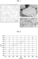
- Fig. 2 shows a diagram plotting a relationship between 0.2% proof stress (YS 18%) and reference strength (HV 60%) under each set of conditions in Table 4.
- YS 18%) 0.2% proof stress
- HV 60% reference strength
- an example of the present invention is represented by a white circle
- a comparative example is represented by a black arrowhead.
- the closer a plotted relationship is to the upper left side the better balance between workability before finishing annealing and high strength after the finishing annealing is indicated by the plotted relationship.
- a cold-rolled annealed material produced in accordance with a production method in accordance with an embodiment of the present invention with use of an austenitic stainless steel having a composition in accordance with an embodiment of the present invention enables both a reduction in load of working during production and an increase in strength of an end product. It is also indicated that such a cold-rolled annealed material is excellent in corrosion resistance at a welded part and is suitable also for uses where a great amount of welding is carried out.
Landscapes
- Chemical & Material Sciences (AREA)
- Engineering & Computer Science (AREA)
- Mechanical Engineering (AREA)
- Materials Engineering (AREA)
- Metallurgy (AREA)
- Organic Chemistry (AREA)
- Physics & Mathematics (AREA)
- Thermal Sciences (AREA)
- Crystallography & Structural Chemistry (AREA)
- Heat Treatment Of Sheet Steel (AREA)
- Heat Treatment Of Steel (AREA)
Abstract
Description
- The present invention relates to an austenitic stainless steel and a method for producing the austenitic stainless steel.
- A metastable austenitic stainless steel typified by SUS301 is known as an austenitic stainless steel which is put to uses where corrosion resistance and strength are required. Such an austenitic stainless steel is used as a material for a spring product such as a cylinder head gasket of an engine in an automobile or for a structural member such as an in-vehicle battery frame member.
- In general, high strength is imparted to such a stainless steel by increasing a rolling reduction ratio in cold rolling or the like, and the load of working such as rolling in the production process therefore tends to be increased. In order to reduce the load, for example, Patent Literature 1 proposes, as a method for producing a spring member having a martensite phase in which a precipitate consisting of a Cu-rich phase is dispersed, a method of subjecting a steel sheet for a spring to an aging treatment which steel sheet exhibits a multiphasic system with no Cu-rich phase precipitated therein.
- [Patent Literature 1]
Japanese Patent Application Publication Tokukai No. 2008-195976 - Precipitation of a Cu-rich phase is effective for increasing the strength of a stainless steel. As such, according to the method disclosed in Patent Literature 1, by subjecting the steel sheet for a spring to the aging treatment to thereby cause a Cu-rich phase to be precipitated, it is possible to increase the strength of a spring member, which is an end product, while reducing the load of working in the production process of the steel sheet for a spring. However, due to the need of the aging treatment step, the method has room for improvement in productivity of the spring member.
- An object of an aspect of the present invention is to provide an austenitic stainless steel which enables both a reduction in load of working during production and an increase in strength of an end product and which can be produced with high productivity.
- Further, the inventor of the present invention paid attention to the fact that, since a temperature at which a Cu-rich phase is precipitated and a temperature at which a Cr carbide is precipitated are relatively close to each other, it is preferable to utilize N without excessively increasing the amount of C, in order to suppress a reduction in corrosion resistance which is caused by precipitation of a Cr carbide. Keeping the amount of C in the austenitic stainless steel to be relatively low is preferable also in terms of achieving the object of reducing the load of working.
- In order to attain the object, an austenitic stainless steel in accordance with an aspect of the present invention is an austenitic stainless steel, containing not less than 0.005% and not more than 0.03% of C, not less than 0.1% and not more than 2.0% of Si, not less than 0.3% and not more than 2.5% of Mn, not more than 0.04% of P, not more than 0.015% of S, not less than 3.0% and less than 6.0% of Ni, not less than 16.0% and not more than 18.5% of Cr, not less than 1.5% and not more than 4.0% of Cu, and not less than 0.08% and not more than 0.25% of N, in percent by mass, and the other part composed of Fe and an inevitable impurity, the austenitic stainless steel including (i) not less than 20% by volume of an austenite phase, (ii) a Cu-rich phase having a number density of not less than 1.0×103 µm-3 and a long diameter of not more than 30 nm, and (iii) a remaining part composed of a deformation-induced martensite phase and an inevitably formed phase, the austenitic stainless steel having an Md30 value of not less than 0.0 and not more than 80.0 as represented by expression (1) below,
Md30 = 551 - 462(C + N) - 9.2Si - 8.1Mn - 29Ni - 10.6Cu - 13.7C r- 18.5Mo - In order to attain the object, a method in accordance with an aspect of the present invention for producing an austenitic stainless steel is a method for producing an austenitic stainless steel, the austenitic stainless steel containing not less than 0.005% and not more than 0.03% of C, not less than 0.1% and not more than 2.0% of Si, not less than 0.3% and not more than 2.5% of Mn, not more than 0.04% of P, not more than 0.015% of S, not less than 3.0% and less than 6.0% of Ni, not less than 16.0% and not more than 18.5% of Cr, not less than 1.5% and not more than 4.0% of Cu, and not less than 0.08% and not more than 0.25% of N, in percent by mass, and the other part composed of Fe and an inevitable impurity, the austenitic stainless steel having an Md30 value of not less than 0.0 and not more than 80.0 as represented by expression (1) below, the method including a finishing annealing step of carrying out finishing annealing at a temperature of not lower than 750°C and not higher than 980°C, wherein in a case where a peak temperature in the finishing annealing step is not lower than 850°C, time during which heating is carried out at not lower than 850°C is not more than 30 seconds, and in the finishing annealing step, an average rate of cooling from 700°C to 500°C after the finishing annealing is not less than 1°C/s,
Md30 = 551 - 462(C + N) - 9.2Si - 8.1Mn - 29Ni - 10.6Cu - 13.7Cr - 18.5Mo - According to an aspect of the present invention, it is possible to provide an austenitic stainless steel which enables both a reduction in load of working during production and an increase in strength of an end product and which can be produced with high productivity.
-
-
Fig. 1 is a diagram illustrating an EBSD grain boundary map and a TEM-captured image of an austenitic stainless steel in accordance with an embodiment. -
Fig. 2 is a diagram illustrating a relationship between 0.2% proof stress (YS 18%) and reference strength (HV 60%) of austenitic stainless steels in accordance with examples and comparative examples. - The following description will discuss in detail an austenitic stainless steel in accordance with an embodiment of the present invention. Note that the following description is intended to make the gist of the present invention understood better, and does not limit the present invention unless otherwise specified.
- The austenitic stainless steel in accordance with an embodiment of the present invention is a stainless steel including not less than 20% by volume of an austenite phase. In the present specification, "austenitic stainless steel" hereinafter means the austenitic stainless steel in accordance with an embodiment of the present invention, unless otherwise specified. The austenitic stainless steel can be, for example, a steel sheet or a steel strip.
- The austenitic stainless steel includes a deformation-induced martensite phase into which a part of the austenite phase has been transformed due to a transformation induced plasticity (TRIP) phenomenon. From the viewpoint of increasing strength, a proportion of the deformation-induced martensite phase in the austenitic stainless steel is preferably not less than 5% by volume, more preferably not less than 10% by volume, even more preferably not less than 15% by volume, and most preferably not less than 20% by volume. Further, the proportion of the deformation-induced martensite phase in the austenitic stainless steel is preferably less than 80% by volume and more preferably not more than 75% by volume. A proportion of the austenite phase included in the austenitic stainless steel can be decreased in accordance with an increase in proportion of the deformation-induced martensite phase, provided that the proportion of the austenite phase is not less than 20% by volume.
- The austenitic stainless steel further includes a Cu-rich phase. The "Cu-rich phase" means a phase containing not less than 60 atomic percent of Cu (copper) and is, for example, an ε-Cu phase. The austenitic stainless steel includes at least a Cu-rich phase having a number density of not less than 1.0×103 µm-3 and a long diameter of not more than 30 nm. The "long diameter" means a maximum diameter among diameters of each of the particles of the Cu-rich phase which is precipitated in particulate form. Note that the austenitic stainless steel can also include a Cu-rich phase having a long diameter of more than 30 nm. The Cu-rich phase can be dispersed in the austenite phase, can be dispersed in the deformation-induced martensite phase, or can be dispersed in an inevitably formed phase (described later).
- The Cu-rich phase can be identified by observing a system with use of a transmission electron microscope (TEM). For example, a TEM sample including a given cross section of the austenitic stainless steel is prepared, and a predetermined portion of the cross section is observed with use of the TEM. This allows counting, in the predetermined portion, the number of Cu-rich phase particles each having a cross section of not more than 30 nm in long diameter. Further, by calculating a volume on the basis of a thickness of the TEM sample used in the number counting and an area of the portion in which the number was counted, it is possible to calculate a number density per volume. The thickness of the TEM sample, for example, can be an actually measured value of thickness of the TEM sample, or can be an estimation value of thickness estimated on the basis of the method by which the TEM sample has been prepared. Examples of the method of preparing the TEM sample include, but are not limited to, electrolytic polishing.
- The finer the precipitated Cu-rich phase and the greater the amount of the precipitated Cu-rich phase, the higher the strength of the austenitic stainless steel. The Cu-rich phase in the above-described size and amount is effective for increasing the strength of the austenitic stainless steel. During the production of the austenitic stainless steel, such as when cold rolling is carried out prior to finishing annealing, precipitation of a Cu-rich phase is not caused. This keeps the strength low and thus reduces the load of working. Then, precipitation of a Cu-rich phase is caused in the finishing annealing step, so that the austenitic stainless steel which has been produced possesses high strength. Production steps such as the finishing annealing step will be described later.
- The austenitic stainless steel can include an inevitably formed phase other than the austenite phase, the deformation-induced martensite phase, and the Cu-rich phase. The inevitably formed phase is not particularly limited, but examples of the inevitably formed phase include a δ ferrite phase and a phase containing a carbide, a nitride, and/or an oxide. Examples of the phase containing a carbide, a nitride, and/or an oxide include a phase containing a carbide or nitride of Cr, Ti, and/or Nb and a phase containing an oxide of Si, Ti, Al, Mg, and/or Ca.
- The austenitic stainless steel has an average crystal grain size of preferably not more than 10.0 pm. The finer the crystal grains of the austenitic stainless steel, the higher the strength of the austenitic stainless steel. In general, increasing the strength of an austenitic stainless steel causes a deterioration in ductility. However, by causing the crystal grains to be finer, it is possible to achieve both an increase in strength and an improvement in ductility of the austenitic stainless steel.
- The average crystal grain size can be measured by an electron back scattering diffraction (EBSD) method. For example, with respect to a given cross section of the austenitic stainless steel, a crystal grain size in each of a plurality of fields of view can be calculated by the EBSD method, and an average value of the crystal grain sizes thus calculated in the plurality of fields of view can be regarded as the average crystal grain size. Further, the average crystal grain size can be measured by a method other than the EBSD method. The method other than the EBSD method can be, for example, a method as indicated in JIS G0551 in which grain boundaries are caused to appear by nitric acid electrolysis and the average crystal grain size is measured using microtomy or the like.
- The austenitic stainless steel contains not less than 0.005% and not more than 0.03% of C, not less than 0.1% and not more than 2.0% of Si, not less than 0.3% and less than 2.5% of Mn, not more than 0.04% of P, not more than 0.015% of S, not less than 3.0% and less than 6.0% of Ni, not less than 16.0% and not more than 18.5% of Cr, not less than 1.5% and not more than 3.8% of Cu, and not less than 0.08% and not more than 0.25% of N, in percent by mass. The other part of the austenitic stainless steel can be composed of Fe (iron) and an inevitable impurity. The following description will discuss the significance of the amount of each element contained in the austenitic stainless steel.
- C (carbon) is an austenite former which facilitates formation of an austenite phase, and is an element which has a high solid-solution strengthening effect and is also effective for obtaining strength. The austenitic stainless steel contains not less than 0.005% by mass and not more than 0.03% by mass of C. In a case where a C content is not less than 0.005% by mass, not only a sufficient solid-solution strengthening effect is exhibited but also an austenitic stainless steel having good strength can be obtained.
- Excessively adding C causes precipitation of a Cr carbide by annealing at a relatively low temperature, and leads to deterioration in corrosion resistance of the austenitic stainless steel, particularly at a welded part. For this reason, the C content is not more than 0.03% by mass. In a case where the C content is not more than 0.03% by mass, it is possible to obtain an austenitic stainless steel that has a good corrosion resistance also at a welded part.
- Si (silicon) is an element which is effective as a deoxidizer and has a solid-solution strengthening effect. The austenitic stainless steel contains not less than 0.1% by mass and not more than 2.0% by mass of Si, and preferably contains not less than 0.2% by mass and not more than 1.0% by mass of Si. In a case where a Si content is not less than 0.1% by mass, the austenitic stainless steel effectively exhibits a deoxidation effect and a solid-solution strengthening effect. It is more preferable that the Si content be not less than 0.2% by mass.
- Further, Si is a ferrite former which facilitates formation of a ferrite phase. A δ ferrite phase can be a cause for occurrence of edge cracking or alligatoring in hot rolling. From the viewpoint of reducing formation of a δ ferrite phase, a Si content is not more than 2.0% by mass, and preferably not more than 1.0% by mass.
- Mn (manganese) is an austenite former, and is also an element effective for maintaining an austenite phase. Further, Mn is an element having an effect of promoting precipitation of a Cu-rich phase. The austenitic stainless steel contains not less than 0.3% by mass and not more than 2.5% by mass of Mn, and preferably contains not less than 0.5% by mass and not more than 2.0% by mass of Mn. In a case where a Mn content is not less than 0.3% by mass, it is easy to ensure the amount of a Cu-rich phase precipitated. It is more preferable that the Mn content be not less than 0.5% by mass. Further, excessively adding Mn causes deterioration in hot workability of the austenitic stainless steel. As such, the Mn content is not more than 2.5% by mass, and preferably not more than 2.0% by mass.
- P (phosphorus) is an element which is mixed in as an inevitable impurity. The lower a P content, the better. From the viewpoint of producibility, the austenitic stainless steel can contain not more than 0.04% by mass of P. In a case where the P content is not more than 0.04% by mass, it is possible to reduce an adverse effect of P on material characteristics of the austenitic stainless steel such as ductility.
- S (sulfur) is an element which is mixed in as an inevitable impurity. The lower a S content, the better. From the viewpoint of producibility, the austenitic stainless steel can contain not more than 0.015% by mass of S. In a case where the S content is not more than 0.015% by mass, it is possible to reduce an adverse effect of S on material characteristics of the austenitic stainless steel such as ductility.
- Ni (nickel) is an austenite former, and is also an element effective for maintaining an austenite phase. The austenitic stainless steel contains not less than 3.0% by mass and less than 6.0% by mass of Ni, preferably contains not less than 3.5% by mass and not more than 5.5% by mass of Ni, and more preferably contains not less than 4.0% by mass and less than 5.0% by mass of Ni. In a case where a Ni content is not less than 3.0% by mass, an austenite phase can be formed and maintained well. It is more preferable that the Ni content be not less than 4.5% by mass.
- However, Ni is an expensive element and, when added excessively, causes a reduction in amount of a deformation-induced martensite phase formed, due to stabilization of an austenite phase. As such, the Ni content is less than 6.0% by mass, preferably not more than 5.5% by mass, and more preferably less than 5.0% by mass.
- Cr (chromium) is an element effective for ensuring corrosion resistance of the austenitic stainless steel. The austenitic stainless steel contains not less than 16.0% by mass and not more than 18.5% by mass of Cr, and more preferably contains not less than 16.5% by mass and not more than 18.0% by mass of Cr. In a case where a Cr content is not less than 16.0% by mass, the corrosion resistance of the austenitic stainless steel can be ensured well. It is more preferable that the Cr content be not less than 16.5% by mass.
- However, Cr is also a ferrite former as with Si. As such, excessively adding Cr causes excessive formation of a δ ferrite phase. As such, the Cr content is not more than 18.5% by mass, and preferably not more than 18.0% by mass.
- Cu is an austenite former, and is also an element effective for maintaining an austenite phase. Further, Cu is effective for increasing the strength of an austenitic stainless steel by precipitation of a Cu-rich phase. Cu is an element which also acts effectively for causing crystal grains to be finer. This is considered to be because a Cu-rich phase exhibits an effect of inhibiting growth of crystal grains. Further, Cu reduces work hardening of an austenite phase in a solid solution state and therefore can reduce the load of rolling in the production process of the austenitic stainless steel.
- The austenitic stainless steel contains not less than 1.5% by mass and not more than 4.0% by mass of Cu, preferably contains not less than 2.0% by mass and not more than 3.5% by mass of Cu, and more preferably contains not less than 2.0% by mass and not more than 3.5% by mass of Cu. In a case where a Cu content is not less than 1.5% by mass, an austenite phase can be formed and maintained well and also a Cu-rich phase can be precipitated well. The Cu content is more preferably not less than 2.0% by mass, and even more preferably more than 2.0% by mass.
- However, excessively adding Cu causes undesirable formation of a CuMn phase at the center of slab during solidification of the slab. This deteriorates hot workability of the slab. As such, the Cu content is not more than 4.0% by mass, and preferably not more than 3.5% by mass.
- N (nitrogen) is an austenite former and is also an element which has a solid-solution strengthening effect and a corrosion resistance improving effect. Since the austenitic stainless steel has a C content of not more than 0.03% by mass in order to ensure the corrosion resistance at a welded part, the austenitic stainless steel has a N content of not less than 0.08% by mass, preferably not less than 0.10% by mass, more preferably not less than 0.11% by mass, and even more preferably not less than 0.12% by mass. A N content within any of the above ranges is effective for ensuring the strength and the corrosion resistance which the austenitic stainless steel is required to have.
- In a case where N is excessively added, the load of rolling of the austenitic stainless steel is increased. As such, the N content is not more than 0.25% by mass, and is preferably not more than 0.20% by mass.
- The austenitic stainless steel can further contain, in addition to the elements described above, at least one selected from the group consisting of: not more than 1.0% of Mo; not more than 1.0% of W; not more than 0.5% of V; not less than 0.0001% and not more than 0.01% of B; not more than 0.8% of Co; not more than 0.1% of Sn; not more than 0.03% of Ca; not more than 0.03% of Mg; not more than 0.5% of Ti; not more than 0.5% of Nb; not more than 0.3% of Al; not more than 0.5% of Sb; not more than 0.5% of Zr; not more than 0.03% of Ta; not more than 0.03% of Hf; and not more than 0.2% of a rare earth metal (REM), in percent by mass.
- Mo (molybdenum), W (tungsten), and V (vanadium) are elements effective for improving corrosion resistance. However, Mo, W, and V are ferrite formers and also expensive elements. As such, it is not preferable to add Mo, W, and V excessively. As such, the austenitic stainless steel preferably contains at least one selected from the group consisting of: not more than 1.0% by mass of Mo; not more than 1.0% by mass of W; and not more than 0.5% by mass of V.
- B (boron) is an element which improves hot workability and is effective for reducing occurrence of edge cracking and alligatoring in hot rolling. The austenitic stainless steel preferably contains not less than 0.0001% by mass and not more than 0.01% by mass of B. A B content of not less than 0.0001% by mass is effective for improving hot workability and reducing occurrence of edge cracking and alligatoring in hot rolling. However, excessively adding B to the austenitic stainless steel containing Cr causes deterioration in corrosion resistance due to precipitation of CraB. As such, the B content is preferably not more than 0.01% by mass.
- Co (cobalt) is an element effective for ensuring corrosion resistance of the austenitic stainless steel. Co also contributes to reducing coarsening of the Cu-rich phase to thereby maintain the fineness of the Cu-rich phase. In order to obtain these effects, it is preferable that Co be contained in an amount of preferably not less than 0.10% by mass. However, Co is an expensive element. From the viewpoint of reducing costs, a Co content is preferably not more than 0.8% by mass.
- Sn (tin) is an element effective for ensuring corrosion resistance of the austenitic stainless steel. Further, excessively adding Sn causes deterioration in hot workability of the austenitic stainless steel. As such, a Sn content is preferably not more than 0.1% by mass.
- Al (aluminum), Ca (calcium), Mg (magnesium), and Ti (titanium) are elements each having a deoxidation effect. The austenitic stainless steel preferably contains, as a deoxidizer, at least one selected from the group consisting of: not more than 0.3% by mass of Al; not more than 0.03% by mass of Ca; not more than 0.03% by mass of Mg; and not more than 0.5% by mass of Ti.
- Nb (niobium) is an element effective for reducing sensitization of the austenitic stainless steel. Nb is also effective for making the system finer and more uniform. The austenitic stainless steel preferably contains not more than 0.5% by mass of Nb.
- Sb (antimony), Zr (zirconium), Ta (tantalum), Hf (hafnium), and REM (rare earth metal) are each an element which improves hot workability and is also effective for oxidation resistance. The austenitic stainless steel preferably contains at least one selected from the group consisting of: not more than 0.5% by mass of Sb; not more than 0.5% by mass of Zr; not more than 0.03% by mass of Ta; not more than 0.03% by mass of Hf; and not more than 0.2% by mass of REM.
- The austenitic stainless steel has an Md30 value, as represented by expression (1) below, of not less than 0.0 and not more than 80.0, and preferably not less than 20.0 and not more than 70.0.
Md30 = 551 - 462(C + N) - 9.2Si - 8.1Mn - 29Ni - 10.6Cu - 13.7Cr - 18.5Mo - An Md30 value of an austenitic stainless steel represents a temperature (°C) at which 50% of a system of a monophasic austenitic stainless steel having only an austenite phase is transformed into a martensite phase when a 30% tensile strain is given to the austenitic stainless steel. As such, an Md30 value can be used as an index of stability of an austenite phase. Further, an Md30 value can be used also as an index that affects a likelihood of occurrence of a TRIP phenomenon in the austenitic stainless steel.
- The austenitic stainless steel in accordance with an embodiment of the present invention has an Md30 value of preferably not less than 0.0 and not more than 80.0. The higher the Md30 value, the more likely for an austenite phase to be transformed into a deformation-induced martensite phase, so that giving a light degree of cold rolling strain enables obtaining high strength and excellent ductility is ensured. Further, also in a case where the austenitic stainless steel is subjected to molding, a portion to which processing strain is given, such as a bent part, tends to have an even higher strength due to a TRIP phenomenon.
- Further, in a production process of the austenitic stainless steel, in order to obtain fine crystal grains by finishing annealing, the presence of a deformation-induced martensite phase in a rolled material before the finishing annealing acts effectively. Such an effect is prominently exhibited in a case where the Md30 value is not less than 0.0. Further, in a case where the Md30 value is more than 80.0, a TRIP phenomenon tends to occur excessively, and the characteristics of the austenitic stainless steel tends not to be stable.
- As such, in a case where the Md30 value, which serves as an index of stability of an austenite phase, is not less than 0.0 and not more than 80.0, it is possible to stably produce the austenitic stainless steel having a high strength and a good ductility.
- Note that, in conventionally known component regression expressions of Md30, it is common that the same value is used as a coefficient of Ni and a coefficient of Cu. In contrast, in an embodiment of the present invention, a coefficient of Cu is set lower than a coefficient of Ni in a component regression expression of Md30. Many of the component regression expressions of Md30 according to the conventional knowledge are based on results obtained from an austenitic stainless steel that is not an austenitic stainless steel with reduced amount of Ni. In contrast, in a component in which the amount of Ni is not reduced as in the present invention, the effect of Cu on stabilization of the austenite phase is clearly less prominent in comparison with the conventional knowledge. This is a novel finding obtained as a result of diligent study by the inventors of the present invention, and the coefficient of Cu in the component regression expression of Md30 has been set on the basis of the finding. This makes it easy to adjust the content of Cu and to increase a degree of freedom in production of the austenitic stainless steel.
- A method for producing an austenitic stainless steel in accordance with an embodiment of the present invention is a method in which the austenitic stainless steel contains not less than 0.005% and not more than 0.03% of C, not less than 0.1% and not more than 2.0% of Si, not less than 0.3% and not more than 2.5% of Mn, not more than 0.04% of P, not more than 0.015% of S, not less than 3.0% and less than 6.0% of Ni, not less than 16.0% and not more than 18.5% of Cr, not less than 1.5% and not more than 4.0% of Cu, and not less than 0.08% and not more than 0.25% of N, in percent by mass, and the other part composed of Fe and an inevitable impurity, the austenitic stainless steel having an Md30 value of not less than 0.0 and not more than 80.0 as represented by expression (1) above. Further, the method for producing an austenitic stainless steel includes a finishing annealing step.
- The method for producing an austenitic stainless steel can include processes for producing a general austenitic stainless steel, except in the finishing annealing step. The following description will discuss an example of the method for producing an austenitic stainless steel in accordance with an embodiment of the present invention, but the present invention is not limited to such an example.
- In the method for producing an austenitic stainless steel in accordance with an embodiment of the present invention, for example, slab is produced by carrying out continuous casting of molten steel containing adjusted components. Then, the slab produced by the continuous casting is heated to a temperature of not lower than 1100°C and not higher than 1300°C, and then is subjected to hot rolling to produce a hot-rolled steel strip. The speed of precipitation of a Cu-rich phase from an austenite phase having little strain after the hot rolling is slow. As such, conditions of a finishing temperature and a winding temperature of the hot-rolled steel strip after the hot rolling can be similar to those of general methods for producing au austenitic stainless steel. From the viewpoint of minimizing precipitation of a Cu-rich phase until finishing annealing, the winding temperature at which the hot-rolled steel strip is wound up after the hot rolling is preferably not higher than 850°C, more preferably not higher than 650°C.
- The hot-rolled steel strip which has been subjected to the hot rolling can be subjected to pickling. Note that annealing can be carried out before the pickling of the hot-rolled steel strip, or the pickling can be carried out without annealing. In a case where the hot-rolled steel strip is subjected to annealing before pickling, an annealing temperature is preferably within a range of not lower than 900°C and not higher than 1150°C. In order to bring Cu completely into a solid solution state, the annealing temperature is more preferably in a range of not lower than 980°C and not higher than 1150°C. The annealing temperature, however, is not limited to these ranges. The hot-rolled steel strip after the pickling is subjected to cold rolling until the hot-rolled steel strip has a predetermined thickness. Thus obtained is a cold-rolled steel strip.
- In the method for producing an austenitic stainless steel, recrystallization and precipitation of a Cu-rich phase progress simultaneously in the finishing annealing step after the cold rolling step. A Cu-rich phase is precipitated particularly easily from a deformation-induced martensite phase. As such, the cold rolling step is carried out preferably at a rolling reduction ratio and a rolling temperature at which a proportion of a deformation-induced martensite phase in the cold-rolled steel strip is not less than 20% by volume of the entire volume of the cold-rolled steel strip. Carrying out the cold rolling step in this manner enables a Cu-rich phase to be effectively precipitated in the steel strip in the subsequent finishing annealing step.
- Note that the austenitic stainless steel has an Md30 value adjusted to not less than 0.0 and not more than 80.0. In the austenitic stainless steel having such an Md30 value, a Cu-rich phase in an amount specified in an embodiment of the present invention is precipitated regardless of an amount of a deformation-induced martensite phase in the cold-rolled steel strip. However, it is even more effective for precipitation of a Cu-rich phase to, as necessary, for example, increase the rolling reduction ratio in the cold rolling step or control the temperature in the cold rolling step to be low.
- From the viewpoint of causing the cold-rolled steel strip to include a deformation-induced martensite phase in a proportion of not less than 20% by volume, for example, the rolling reduction ratio in the cold rolling step is preferably not less than 40%, more preferably not less than 50%, and even more preferably not less than 60%. Further, the temperature in the cold rolling step is preferably not higher than 90°C and more preferably not higher than 60°C.
- The cold-rolled steel strip is subjected to finishing annealing. The finishing annealing step is carried out under conditions that cause precipitation of a Cu-rich phase to proceed. A Cu-rich phase is effective for increasing the strength of the austenitic stainless steel. As such, the hot-rolled steel strip and the cold-rolled steel strip before precipitation of a Cu-rich phase are each relatively low in strength, and the load of rolling in the cold rolling step can therefore be reduced. Then, a Cu-rich phase is precipitated in the finishing annealing step, so that the austenitic stainless steel after the finishing annealing step is able to have high strength.
- Further, the precipitation of a Cu-rich phase is effective for causing recrystallized grains of an austenite phase to be finer. As such, utilizing the precipitation of a Cu-rich phase makes it possible to control an average crystal grain size to be not more than 10.0 pm.
- Thus, according to the method in accordance with an embodiment of the present invention for producing an austenitic stainless steel, both a reduction in load of working during production and an increase in strength of an end product can be achieved to significant degrees. Further, since an additional step conventionally required, i.e., an aging treatment step, is not required in the precipitation of a Cu-rich phase, the austenitic stainless steel can be produced with good productivity.
- The temperature of finishing annealing in the finishing annealing step is not lower than 750°C and not higher than 980°C, and preferably not lower than 800°C and not higher than 925°C, in order for a Cu-rich phase to be effectively precipitated in the austenitic stainless steel. In a case where the temperature of the finishing annealing is lower than 750°C, the system is insufficiently recrystallized. In a case where the temperature of the finishing annealing is higher than 980°C, the Cu-rich phase is dissolved, so that the amount of a Cu-rich phase remaining after the finishing annealing is insufficient.
- Further, a Cu-rich phase precipitated from a deformation-induced martensite phase is dissolved particularly easily in an austenite phase when the Cu-rich phase is maintained at a temperature not lower than 850°C for a long time in the finishing annealing. As such, in a case where a peak temperature in the finishing annealing step is not lower than 850°C, it is preferable that time during which heating is carried out at not lower than 850°C be short. Specifically, in a case where a peak temperature in the finishing annealing step is not lower than 850°C, time during which heating is carried out at not lower than 850°C is not more than 30 seconds, and preferably not more than 15 seconds. In a case where there are a plurality of times during each of which the temperature in the finishing annealing step is not lower than 850°C, the "time during which heating is carried out at not lower than 850°C" means a total of the respective lengths of those times.
- Since the austenitic stainless steel has a C content of not more than 0.03% by mass, precipitation of a Cr carbide during cooling is less likely to occur. As such, a rate of cooling after the finishing annealing can be similar to those of general methods for producing a stainless steel. From the viewpoint of productivity, the rate of cooling is preferably high. However, for example, an average rate of cooling from 700°C to 500°C can be a relatively low rate of not less than 1°C/s, and preferably not less than 5°C/s in consideration of productivity. Further, in consideration of flatness of the steel sheet, the rate of cooling is preferably less than 75°C/s, more preferably not more than 50°C/s.
- Note that, as necessary, process annealing and intermediate rolling can be carried out in the cold rolling step. The steel strip after the finishing annealing can be subjected to temper rolling, as necessary, in order to further increase the strength. The temperature of the process annealing is preferably not lower than 980°C and not higher than 1150°C in order to avoid precipitation of a Cu-rich phase, in a case where a reduction in load of rolling has priority. In terms of obtaining high strength by repeating a precipitation process, the conditions of the temperature of the process annealing are preferably the same as those of the finishing annealing. Note that the temperature of the process annealing is not limited to the above-described ranges.
- The austenitic stainless steel in accordance with an embodiment of the present invention is an austenitic stainless steel whose strength is kept relatively low in the production process to achieve a reduction in load of rolling and which possesses high strength after being produced. This characteristic of the austenitic stainless steel can be represented, for example, by a relationship between 0.2% proof stress (YS 18%, MPa) and reference strength (HV 60%).
- 0.2% proof stress (YS 18%) is an index of strength of the austenitic stainless steel. 0.2% proof stress (YS 18%) indicates 0.2% proof stress exhibited by the austenitic stainless steel in a case where the austenitic stainless steel has been subjected to finishing annealing and then to temper rolling causing an elongation of 18%. 0.2% proof stress can be evaluated using a method in conformity with JIS Z2241.
- Reference strength (HV 60%) is an index hypothetically indicating strength of the austenitic stainless steel before precipitation of a Cu-rich phase is caused in the finishing annealing step. Reference strength (HV 60%) indicates Vickers hardness exhibited by an austenitic stainless steel which has the same composition but has been produced by a method partially changed from the production method in accordance with an embodiment of the present invention such that: annealing is carried out at 1050°C after the hot rolling; and cold rolling is carried out at a rolling reduction ratio of 60%. That is, reference strength (HV 60%) does not have to indicate strength of the austenitic stainless steel in accordance with an embodiment of the present invention, but can be, for example, strength of a steel strip prepared for evaluation. Vickers hardness can be measured by a Vickers hardness test method in conformity with JIS Z2244.
- The inventors of the present invention have found that an austenitic stainless steel which enables both a reduction in load of working during production and an increase in strength of an end product exhibits 0.2% proof stress (YS 18%) and reference strength (HV 60%) which are in a relationship satisfying expression (2) below.

- According to the method in accordance with an embodiment of the present invention, it is possible to produce an austenitic stainless steel that satisfies expression (2) above and enables both a reduction in load of working during production and an increase in strength of an end product.
- The austenitic stainless steel has extremely high strength and corrosion resistance. As such, the austenitic stainless steel is suitable for use as a material for a spring product that is required to have high strength and corrosion resistance, such as a cylinder head gasket, a flat spiral spring, a spring for an electronic device component, a member for a train carriage, an in-vehicle battery frame member, a structural member, and a metal gasket. In particular, also in a case where the austenitic stainless steel is welded, the austenitic stainless steel is excellent in corrosion resistance at a welded part (weldability). As such, the austenitic stainless steel in accordance with an embodiment of the present invention is suitably applicable even to uses in which the number of welded structures is relatively large, such as a member for a train carriage or an in-vehicle battery frame member produced to be used by being welded.
- Aspects of the present invention can also be expressed as follows:
An austenitic stainless steel in accordance with Aspect 1 of the present invention is an austenitic stainless steel, containing not less than 0.005% and not more than 0.03% of C, not less than 0.1% and not more than 2.0% of Si, not less than 0.3% and not more than 2.5% of Mn, not more than 0.04% of P, not more than 0.015% of S, not less than 3.0% and less than 6.0% of Ni, not less than 16.0% and not more than 18.5% of Cr, not less than 1.5% and not more than 4.0% of Cu, and not less than 0.08% and not more than 0.25% of N, in percent by mass, and the other part composed of Fe and an inevitable impurity, the austenitic stainless steel including (i) not less than 20% by volume of an austenite phase, (ii) a Cu-rich phase having a number density of not less than 1.0×103 µm-3 and a long diameter of not more than 30 nm, and (iii) a remaining part composed of a deformation-induced martensite phase and an inevitably formed phase, the austenitic stainless steel having an Md30 value of not less than 0.0 and not more than 80.0 as represented by expression (1) below,Md30 = 551 - 462(C + N) - 9.2Si - 8.1Mn - 29Ni - 10.6Cu - 13.7Cr - 18.5Mo - In Aspect 2 of the present invention, the austenitic stainless steel in accordance with Aspect 1 can be configured such that the austenitic stainless steel further contains at least one selected from the group consisting of: not more than 1.0% of Mo; not more than 1.0% of W; not more than 0.5% of V; not less than 0.0001% and not more than 0.01% of B; not more than 0.8% of Co; not more than 0.1% of Sn; not more than 0.03% of Ca; not more than 0.03% of Mg; not more than 0.5% of Ti; not more than 0.5% of Nb; not more than 0.3% of Al; not more than 0.5% of Sb; not more than 0.5% of Zr; not more than 0.03% of Ta; not more than 0.03% of Hf; and not more than 0.2% of a rare earth metal, REM, in percent by mass.
- In Aspect 3 of the present invention, the austenitic stainless steel in accordance with Aspect 1 or 2 can be configured such that the austenitic stainless steel has an average crystal grain size of not more than 10.0 pm.
- A method in accordance with Aspect 4 of the present invention for producing an austenitic stainless steel is a method for producing an austenitic stainless steel, the austenitic stainless steel containing not less than 0.005% and not more than 0.03% of C, not less than 0.1% and not more than 2.0% of Si, not less than 0.3% and not more than 2.5% of Mn, not more than 0.04% of P, not more than 0.015% of S, not less than 3.0% and less than 6.0% of Ni, not less than 16.0% and not more than 18.5% of Cr, not less than 1.5% and not more than 4.0% of Cu, and not less than 0.08% and not more than 0.25% of N, in percent by mass, and the other part composed of Fe and an inevitable impurity, the austenitic stainless steel having an Md30 value of not less than 0.0 and not more than 80.0 as represented by expression (1) below, the method including a finishing annealing step of carrying out finishing annealing at a temperature of not lower than 750°C and not higher than 980°C, wherein in a case where a peak temperature in the finishing annealing step is not lower than 850°C, time during which heating is carried out at not lower than 850°C is not more than 30 seconds, and in the finishing annealing step, an average rate of cooling from 700°C to 500°C after the finishing annealing is not less than 1°C/s,
Md30 = 551 - 462(C + N) - 9.2Si - 8.1Mn - 29Ni - 10.6Cu - 13.7Cr - 18.5Mo - The present invention is not limited to the embodiments, but can be altered by a skilled person in the art within the scope of the claims. The present invention also encompasses, in its technical scope, any embodiment derived by combining technical means disclosed in differing embodiments.
- The following description will discuss results of evaluation of austenitic stainless steels in accordance with inventive examples of the present invention and austenitic stainless steels in accordance with comparative examples.
- Table 1 below shows compositions (in percent by mass) and Md30 values of austenitic stainless steels in accordance with examples of the present invention (Inventive Steels A1 to A15) and austenitic stainless steels in accordance with comparative examples (Comparative Steels B1 to B5). The Md30 values were calculated by expression (1) above. Note that underlined values in Table 1 below are each a value that falls outside a range specified in the present invention. The same is true of Table 2 below.


- The austenitic stainless steels in accordance with the examples of the present invention and the austenitic stainless steels in accordance with the comparative examples were produced by methods described below. Each of the austenitic stainless steels having the compositions indicated in Table 1 was dissolved and was subjected to processes from hot rolling to finishing annealing in accordance with a production method in accordance with an embodiment of the present invention (Inventive Examples C1 to C8) or a production method in accordance with a comparative example (Comparative Examples D1 and D2) to obtain a cold-rolled annealed material. Conditions of each production method are indicated in Table 2.
[Table 2] Thickness after hot rolling (mm) Annealing after hot rolling Thickness after cold rolling (mm) Temperature of finishing anne aling Time during which temperature is not lower than 850°C Inventive Example C1 5 NA 1.5 890°C 5s Inventive Example C2 5 1050°C 1.5 870°C 3s Inventive Example C3 4 1100°C 1.2 850°C 1 s Inventive Example C4 3.5 NA 1 830°C - Inventive Example C5 3.5 1050°C 1.5 870°C 3s Inventive Example C6 3 1000°C 1 860°C 3s Inventive Example C7 4 NA 1.2 910°C 10 s Inventive Example C8 3.5 1120°C 1 930°C 20 s Comparative Example D1 3 1050°C 1 990°C 40 s Comparative Example D2 4 1080°C 1.2 900°C 65 s - In the finishing annealing step, in a case where the finishing annealing temperature was not lower than 850°C, time during which the finishing annealing temperature was not lower than 850°C was adjusted as indicated in Table 2. Note that in Inventive Example C3, heating was adjusted such that the temperature of the finishing annealing would start to decrease at a point in time when the temperature reached 850°C, but in Table 2, time during which the temperature was not lower than 850°C is indicated as "1 s" for convenience.
- The austenitic stainless steels in accordance with the examples of the present invention and the austenitic stainless steels in accordance with the comparative examples were evaluated as follows with respect to various indices.
- From a cold-rolled annealed material produced under each set of conditions, a TEM sample was prepared by electrolytic polishing. On a surface of the TEM sample which surface was parallel to a rolling direction of the cold-rolled annealed material, three fields of view each in a size of 400 nm×400 nm were observed. On the basis of contrasts in a TEM image, a Cu-rich phase was identified and the number of Cu-rich phase particles were counted. Assuming that the TEM sample had a thickness of 150 nm, a number density per unit volume was determined. When a Cu-rich phase was coarse, the Cu-rich phase was observed in clear shapes instead of contrasts. Cu-rich phase particles each having a long diameter of more than 30 nm were excluded from the counting.
- An average crystal grain size was evaluated by the EBSD method. A cross section of the cold-rolled annealed material produced under each set of conditions which cross section was parallel to the rolling direction and perpendicular to the rolled surface was subjected to mechanical polishing and then to electrolytic polishing. Then, in a field of view with a magnification of 2000 times, a 40 µm×40 pm portion in the cross section was subjected to EBSD analysis at step intervals of 0.2 pm. With respect to an orientation difference in a crystallographic orientation relationship that satisfies a coincidence grain boundary of Σ3, an annealing twin with an orientation difference of not more than 1° was excluded, and a boundary with an orientation difference of not less than 2° was regarded as a grain boundary. A crystal grain size was calculated by expression (3) below where S (µm2) was an area of each crystal grain and D (pm) was a diameter of a circle having the same area as the crystal grain. This operation was carried out with respect to five fields of view, and an average of crystal grain sizes obtained in the respective five fields of view was calculated as an average crystal grain size.

- An amount (percent by volume) of a martensite phase was measured as follows. In a case where a material which had been subjected to cold rolling or a material which had been subjected to temper rolling had a thickness of not less than 1.5 mm, the material was used as it was. In a case where a material which had been subjected to cold rolling or a material which had been subjected to temper rolling had a thickness of less than 1.5 mm, a plurality of strips of the material were laid on top of each other so that a total thickness was not less than 1.5 mm. These materials were subjected to measurement with use of a ferrite scope (FMP30, manufactured by Fischer, electromagnetic induction method), and a value thus measured was divided by 0.7475 to obtain a value which was regarded as an amount of the martensite phase. An amount (percent by volume) of an austenite phase was assumed to be a value obtained by subtracting the amount of the martensite phase from 100% by volume of the entire matrix of the austenitic stainless steel. An amount of a Cu-rich phase and an amount of an inevitably formed phase accounted for only a small part of the austenitic stainless steel and were difficult to accurately measure. As such, the amount of the Cu-rich phase and the amount of the inevitably formed phase can be calculated as extra numbers.
- As an index of tensile characteristics, evaluation was made of 0.2% proof stress (YS 18%) exhibited in a case where temper rolling causing an elongation of 18% was carried out. The 0.2% proof stress (YS 18%) was measured by preparing a JIS #13 B test piece and conducting a tensile test in conformity with JIS Z2241. The 0.2% proof stress (YS 18%) was measured at a crosshead speed of 3 mm/min.
- Among the conditions of examples of the present invention and the conditions of examples, production conditions were partially changed such that annealing of a hot-rolled steel strip was carried out at 1050°C and cold rolling was carried out at a rolling reduction ratio of 60% to obtain a 60% rolled material. A Vickers hardness of the 60% rolled material was measured as a reference strength (HV 60%). The Vickers hardness was measured by a Vickers hardness test (JIS Z2244) with use of a Vickers hardness tester with respect to a surface of the 60% rolled material. A load at the time of measurement in the Vickers hardness test was 10 kg.
- A cold-rolled annealed material having a strip thickness of 1.5 mm was subjected to melt run welding by TIG under the conditions of an electrode diameter of 1.6 mm, a welding speed of 70 cm/min, a welding current of 90 A, and an Ar gas seal. A 10 mm×10 mm portion including a welded part was regarded as a surface to be evaluated, and was sanded with #600 sanding paper in order to eliminate an effect of a coating film. Then, corrosion resistance on the surface to be evaluated was evaluated with use of an electrochemical reactivation rate as an index.
- The reactivation rate was measured in conformity with JIS G0580. Specifically, in an aqueous solution of 0.5 mol/L of sulfuric acid and 0.01 mol/L of potassium thiocyanate at a temperature of 30°C, polarization was carried out from a natural potential to 0.3 V (vsSCE) at a sweep rate of 100 mV/min (hereinafter referred to as "forward operation"). After 0.3 V (vsSCE) was reached, the potential was swept in a direction reverse to that of the forward operation, and after the hot-rolled material was reactivated, the sweeping was ended at a potential at which the anode current was 0 again (hereinafter referred to as "backward operation").
- A ratio of a maximum current density ia in the forward operation to a maximum current density ir in the backward operation (ir/ia) was calculated as a reactivation rate. This evaluation method is strict for a method for determining sensitization, which is a method for evaluating corrosion resistance. As such, even a reactivation rate of, for example, approximately 1.5% is considered to cause no problem in an actual environment. However, the cold-rolled annealed materials in accordance with the examples of the present invention can have fine crystal grains and therefore can be difficult to evaluate in terms of corrosion resistance. In consideration of this fact, the cold-rolled annealed materials in accordance with the examples of the present invention can be considered to have good corrosion resistance in a case where the reactivation rate is not more than 1%. As such, the corrosion resistance at the welded part was evaluated to be "good" in a case where the reactivation rate was not more than 1% and "poor" in a case where the reactivation rate was more than 1%.
- With respect to Inventive Steel A2, an amount of a Cu-rich phase precipitated and a crystal grain size of the cold-rolled annealed material obtained under each set of conditions indicated in Table 2 are shown in Table 3 below. Further, 0.2% proof stress (YS 18%), an amount of a martensite phase after temper rolling causing an elongation of 18% was carried out after cold rolling (before finishing annealing), and an amount of a martensite phase after temper rolling causing an elongation of 18% was carried out after finishing annealing, under each set of conditions, are also shown in Table 3 below.
- Note that, in Table 3 below, each underline indicates that the amount of a Cu-rich phase precipitated falls outside a range specified in the present invention.
[Table 3] Amount of martensite after cold rolling (vol%) Amount of Cu precipitated (µm-3) Crystal grain size (µm) YS 18% (MPa) Amount of martensite after temper rolling (vol%) Inventive Example C1 55 2.0×10³ 3 1150 15 Inventive Example C2 60 3.3×10³ 2.6 1157 12 Inventive Example C3 63 4.5×10³ 2.4 1160 8 Inventive Example C4 59 6.2×10³ 2 1172 10 Inventive Example C5 40 2.5×10³ 2.8 1142 15 Inventive Example C6 55 2.8×10³ 2.6 1153 14 Inventive Example C7 61 2.0×10³ 3.4 1138 18 Inventive Example C8 63 1.6×10³ 7 1120 23 Comparative Example D1 65 NA 18 1030 31 Comparative Example D2 65 NA 5 1026 25 - With respect to Inventive Steel A2, cold-rolled annealed materials produced by the respective sets of conditions of Inventive Examples C1 to C8 each had an amount of a Cu-rich phase precipitated which fell within the range specified in the present invention and exhibited a very small average crystal grain size of not more than 10.0 pm. In contrast, neither of the cold-rolled annealed materials produced under the respective sets of conditions of Comparative Examples D1 and D2 exhibited precipitation of a Cu-rich phase.
- With respect to Inventive Steel A2, an EBSD grain boundary map and a TEM-captured image are shown on a left side and a right side, respectively, of
Fig. 1 with respect to the cold-rolled annealed material produced under the conditions of Inventive Example C2. As indicated in the TEM-captured image on the right side ofFig. 1 , precipitation of a Cu-rich phase (illustrated as "Cu" inFig. 1 ) was observed in the austenitic stainless steel in accordance with an embodiment of the present invention. - Further, since the reference strength (HV 60%) of Inventive Steel A2 was 445, the 0.2% proof stress (YS 18%) is preferably not less than 1094 MPa according to expression (2) above. The cold-rolled annealed materials of Inventive Steel A2 produced under the respective sets of conditions of Inventive Examples C1 to C8 each exhibited a 0.2% proof stress (YS 18%) of not less than 1094 MPa. In contrast, the cold-rolled annealed materials produced under the respective sets of conditions of Comparative Examples D1 and D2 each exhibited a 0.2% proof stress (YS 18%) of less than 1094 MPa. The above indicates that under the sets of conditions of Comparative Examples D1 and D2, precipitation of a Cu-rich phase does not occur, and it is therefore difficult to obtain an austenitic stainless steel having a good balance between workability before finishing annealing and high strength after the finishing annealing.
- Next, Table 4 below indicates (i) an amount of a Cu-rich phase precipitated in a cold-rolled annealed material produced from Inventive Steels A1 to A15 or Comparative Steels B1 to B5 under the set of production conditions indicated in Inventive Example C2 and (ii) a crystal grain size of the cold-rolled annealed material, the amount of a Cu-rich phase precipitated and the crystal grain size being exhibited by after finishing annealing. Further, Table 4 below also indicates 0.2% proof stress (YS 18%), reference strength (HV 60%), and corrosion resistance at the welded part under these conditions.
- Note that, in Table 4 below, each underlined portion indicates that (i) the amount of a Cu-rich phase precipitated fell outside the range specified in the present invention, (ii) the value of 0.2% proof stress (YS 18%) did not satisfy expression (2) above, or (iii) the corrosion resistance at the welded part was poor.
[Table 4] Amount of Cu precipitated (µm-3) Crystal grain size (µm) YS 18% (MPa) HV 60% Corrosion resistance at welded part Inventive Steel A1 3.5×10³ 3.0 1080 430 Good Inventive Steel A2 3.3×10³ 2.6 1150 445 Good Inventive Steel A3 3.8×10³ 3.5 1130 450 Good Inventive Steel A4 2.3×10³ 3.0 1050 425 Good Inventive Steel A5 3.3×10³ 3.4 1090 440 Good Inventive Steel A6 5.0×10³ 2.5 1100 435 Good Inventive Steel A7 3.8×10³ 2.1 1060 430 Good Inventive Steel A8 4.2×10³ 2.2 1100 445 Good Inventive Steel A9 1.5×10³ 2.9 1100 452 Good Inventive Steel A10 3.0×10³ 3.4 1140 450 Good Inventive Steel A11 3.4×10³ 4.2 1160 455 Good Inventive Steel A12 3.6×10³ 4.0 1150 455 Good Inventive Steel A13 3.2×10³ 1.9 1150 450 Good Inventive Steel A14 2.4×10³ 3.2 1060 435 Good Inventive Steel A15 3.1×10³ 3.5 1100 440 Good Comparative Steel B1 3.1×10³ 3.2 1240 480 Poor Comparative Steel B2 3.3×10³ 2.9 920 420 Good Comparative Steel B3 0.3×10³ 6.2 980 425 Good Comparative Steel B4 5.3×10³ 3.2 940 480 Good Comparative Steel B5 Not precipitated 7.8 940 460 Good - The cold-rolled annealed materials of Inventive Steels A1 to A15 each had an amount of a Cu-rich phase precipitated falling within the range specified in the present invention and exhibited a very small average crystal grain size of not more than 10.0 pm. Further, the cold-rolled annealed materials each exhibited 0.2% proof stress (YS 18%) with a good value satisfying expression (2) above.
- In contrast, the cold-rolled annealed material of Comparative Steel B1 had a poor corrosion resistance at the welded part. The cold-rolled annealed materials of Comparative Steels B2 to B5 exhibited a 0.2% proof stress (YS 18%) that did not satisfy expression (2) above, and it was thus not possible to obtain an austenitic stainless steel having a good balance between workability before finishing annealing and high strength after the finishing annealing.
-
Fig. 2 shows a diagram plotting a relationship between 0.2% proof stress (YS 18%) and reference strength (HV 60%) under each set of conditions in Table 4. InFig. 2 , an example of the present invention is represented by a white circle, and a comparative example is represented by a black arrowhead. In the graph shown inFig. 2 , the closer a plotted relationship is to the upper left side, the better balance between workability before finishing annealing and high strength after the finishing annealing is indicated by the plotted relationship. - Note that the above-described results each pertain to a cold-rolled annealed material obtained under the condition of a cooling rate after finishing annealing of 25°C/s. Now, with use of Inventive Steels A1, A2, and A5, respective cold-rolled annealed materials were produced under the conditions of Inventive Example C2 indicated in Table 2 except that the cooling rate from 700°C to 500°C after the finishing annealing was changed within a range of 0.3°C/s to 100°C/s. An amount of a Cu-rich phase precipitated in each of the resultant cold-rolled annealed materials is shown in Table 5 below.
[Table 5] Cooling rate Amount of Cu precipitated (µm-3) °C/s A1 A2 A5 0.3 0.7×10³ 0.8×10³ 0.6×10³ 0.6 0.9×10³ 0.9×10³ 0.9×10³ 1.2 1.2×10³ 1.2×10³ 1.3×10³ 2 2.4×10³ 2.8×10³ 2.1×10³ 5 3.5×10³ 3.3×10³ 3.3×10³ 25 3.5×10³ 3.3×10³ 3.3×10³ 60 3.5×10³ 3.3×10³ 3.3×10³ 100 3.5×10³ 3.3×10³ 3.3×10³ - At a cooling rate of not less than 5°C/s, no change was observed in the amount of Cu precipitated in the cold-rolled annealed material. It can be said that in a case where the cooling rate is sufficiently high, coarsening of a Cu-rich phase during the cooling and resultant loss of the Cu-rich phase do not occur. When the cooling rate was 2°C/s, a slight decrease in amount of Cu precipitated was observed. This is considered to be because coarsening of a Cu-rich phase during the cooling and resultant loss of the Cu-rich phase occurred. This is a phenomenon generally referred to as Ostwald ripening. In a case where the cooling rate was less than 1°C/s, coarsening of a Cu-rich phase during the cooling and resultant loss of the Cu-rich phase were further promoted, so that the amount of precipitation was less than 1.0×103 µm-3.
- As shown in Table 4 and
Fig. 2 , it is indicated that a cold-rolled annealed material produced in accordance with a production method in accordance with an embodiment of the present invention with use of an austenitic stainless steel having a composition in accordance with an embodiment of the present invention enables both a reduction in load of working during production and an increase in strength of an end product. It is also indicated that such a cold-rolled annealed material is excellent in corrosion resistance at a welded part and is suitable also for uses where a great amount of welding is carried out.
Claims (4)
- An austenitic stainless steel, comprising not less than 0.005% and not more than 0.03% of C, not less than 0.1% and not more than 2.0% of Si, not less than 0.3% and not more than 2.5% of Mn, not more than 0.04% of P, not more than 0.015% of S, not less than 3.0% and less than 6.0% of Ni, not less than 16.0% and not more than 18.5% of Cr, not less than 1.5% and not more than 4.0% of Cu, and not less than 0.08% and not more than 0.25% of N, in percent by mass, and the other part composed of Fe and an inevitable impurity,the austenitic stainless steel including (i) not less than 20% by volume of an austenite phase, (ii) a Cu-rich phase having a number density of not less than 1.0×103 µm-3 and a long diameter of not more than 30 nm, and (iii) a remaining part composed of a deformation-induced martensite phase and an inevitably formed phase,the austenitic stainless steel having an Md30 value of not less than 0.0 and not more than 80.0 as represented by expression (1) below,
Md30 = 551 - 462(C + N) - 9.2Si - 8.1Mn - 29Ni - 10.6Cu - 13.7Cr - 18.5Mo wherein in expression (1) above, a content, in percent by mass, of each element contained in the austenitic stainless steel is substituted into a corresponding element symbol, and 0 is substituted into an element symbol of an element not added to the austenitic stainless steel. - The austenitic stainless steel as set forth in claim 1, further comprising at least one selected from the group consisting of: not more than 1.0% of Mo; not more than 1.0% of W; not more than 0.5% of V; not less than 0.0001% and not more than 0.01% of B; not more than 0.8% of Co; not more than 0.1% of Sn; not more than 0.03% of Ca; not more than 0.03% of Mg; not more than 0.5% of Ti; not more than 0.5% of Nb; not more than 0.3% of Al; not more than 0.5% of Sb; not more than 0.5% of Zr; not more than 0.03% of Ta; not more than 0.03% of Hf; and not more than 0.2% of a rare earth metal, REM, in percent by mass.
- The austenitic stainless steel as set forth in claim 1 or 2, having an average crystal grain size of not more than 10.0 µm.
- A method for producing an austenitic stainless steel, the austenitic stainless steel containing not less than 0.005% and not more than 0.03% of C, not less than 0.1% and not more than 2.0% of Si, not less than 0.3% and not more than 2.5% of Mn, not more than 0.04% of P, not more than 0.015% of S, not less than 3.0% and less than 6.0% of Ni, not less than 16.0% and not more than 18.5% of Cr, not less than 1.5% and not more than 4.0% of Cu, and not less than 0.08% and not more than 0.25% of N, in percent by mass, and the other part composed of Fe and an inevitable impurity, the austenitic stainless steel having an Md30 value of not less than 0.0 and not more than 80.0 as represented by expression (1) below,said method comprising a finishing annealing step of carrying out finishing annealing at a temperature of not lower than 750°C and not higher than 980°C,wherein in a case where a peak temperature in the finishing annealing step is not lower than 850°C, time during which heating is carried out at not lower than 850°C is not more than 30 seconds, andin the finishing annealing step, an average rate of cooling from 700°C to 500°C after the finishing annealing is not less than 1°C/s,
Md30 = 551 - 462(C + N) - 9.2Si - 8.1Mn - 29Ni - 10.6Cu - 13.7Cr - 18.5Mo wherein in expression (1) above, a content, in percent by mass, of each element contained in the austenitic stainless steel is substituted into a corresponding element symbol, and 0 is substituted into an element symbol of an element not added to the austenitic stainless steel.
Applications Claiming Priority (2)
| Application Number | Priority Date | Filing Date | Title |
|---|---|---|---|
| JP2022019593 | 2022-02-10 | ||
| PCT/JP2023/001835 WO2023153184A1 (en) | 2022-02-10 | 2023-01-23 | Austenitic stainless steel and method for producing austenitic stainless steel |
Publications (2)
| Publication Number | Publication Date |
|---|---|
| EP4477775A1 true EP4477775A1 (en) | 2024-12-18 |
| EP4477775A4 EP4477775A4 (en) | 2025-12-31 |
Family
ID=87564041
Family Applications (1)
| Application Number | Title | Priority Date | Filing Date |
|---|---|---|---|
| EP23752652.0A Pending EP4477775A4 (en) | 2022-02-10 | 2023-01-23 | AUSTENITIC STAINLESS STEEL AND METHOD FOR PRODUCING AUSTENITIC STAINLESS STEEL |
Country Status (6)
| Country | Link |
|---|---|
| US (1) | US20250066869A1 (en) |
| EP (1) | EP4477775A4 (en) |
| JP (1) | JP7758973B2 (en) |
| KR (1) | KR102981265B1 (en) |
| CN (1) | CN118541502A (en) |
| WO (1) | WO2023153184A1 (en) |
Family Cites Families (7)
| Publication number | Priority date | Publication date | Assignee | Title |
|---|---|---|---|---|
| JPH04191352A (en) * | 1990-11-26 | 1992-07-09 | Nisshin Steel Co Ltd | Gasket material for internal combustion engine excellent in settling resistance |
| JP5100144B2 (en) | 2007-02-08 | 2012-12-19 | 日新製鋼株式会社 | Steel plate for spring, spring material using the same, and manufacturing method thereof |
| JP5500960B2 (en) * | 2009-12-01 | 2014-05-21 | 新日鐵住金ステンレス株式会社 | Fine grain austenitic stainless steel sheet with excellent stress corrosion cracking resistance and workability |
| WO2014157146A1 (en) * | 2013-03-26 | 2014-10-02 | 日新製鋼株式会社 | Austenitic stainless steel sheet and method for manufacturing high-strength steel material using same |
| KR101952054B1 (en) * | 2014-09-25 | 2019-02-25 | 신닛테츠스미킨 카부시키카이샤 | Austenitic stainless steel sheet and method for producing same |
| JP6519023B2 (en) | 2016-05-17 | 2019-05-29 | Jfeスチール株式会社 | Ferritic stainless steel for kitchen equipment and method of manufacturing the same |
| JP7598219B2 (en) * | 2020-10-14 | 2024-12-11 | 日鉄ステンレス株式会社 | Austenitic stainless steel and method for producing same |
-
2023
- 2023-01-23 CN CN202380017038.7A patent/CN118541502A/en active Pending
- 2023-01-23 KR KR1020247022501A patent/KR102981265B1/en active Active
- 2023-01-23 US US18/726,393 patent/US20250066869A1/en active Pending
- 2023-01-23 EP EP23752652.0A patent/EP4477775A4/en active Pending
- 2023-01-23 JP JP2023580150A patent/JP7758973B2/en active Active
- 2023-01-23 WO PCT/JP2023/001835 patent/WO2023153184A1/en not_active Ceased
Also Published As
| Publication number | Publication date |
|---|---|
| JP7758973B2 (en) | 2025-10-23 |
| KR102981265B1 (en) | 2026-06-22 |
| US20250066869A1 (en) | 2025-02-27 |
| EP4477775A4 (en) | 2025-12-31 |
| JPWO2023153184A1 (en) | 2023-08-17 |
| CN118541502A (en) | 2024-08-23 |
| WO2023153184A1 (en) | 2023-08-17 |
| KR20240118837A (en) | 2024-08-05 |
Similar Documents
| Publication | Publication Date | Title |
|---|---|---|
| EP2617852B1 (en) | High-strength hot-rolled steel sheet having excellent bending workability and method for producing same | |
| KR100733016B1 (en) | Тi-added ferritic stainless steel sheet and its manufacturing method | |
| EP2586886B1 (en) | High-tension/hot-rolled steel sheet having excellent workability, and method for producing same | |
| EP2759613B1 (en) | High-tensile-strength hot-rolled steel sheet and method for producing same | |
| EP2765211B1 (en) | High-tensile-strength hot-rolled steel sheet and method for producing same | |
| EP3342891B1 (en) | Steel sheet | |
| JP2019218613A (en) | Ferrite austenite two-phase stainless steel sheet and weldment structure, and manufacturing method therefor | |
| EP4640928A1 (en) | Ni-plated steel sheet for canning, and manufacturing method therefor | |
| EP2578714B1 (en) | Hot-rolled high-strength steel sheet and process for production thereof | |
| EP3666917A1 (en) | Ferritic stainless-steel sheet and method for manufacturing same | |
| EP3670692B1 (en) | Ferritic stainless steel | |
| JP7598219B2 (en) | Austenitic stainless steel and method for producing same | |
| EP2922978B1 (en) | Ferritic stainless steel | |
| EP4477776A1 (en) | Austenitic stainless steel and method for producing austenitic stainless steel | |
| EP2993245B1 (en) | High-strength low-specific gravity steel sheet having superior spot weldability | |
| EP4261305A1 (en) | High strength plated steel sheet having excellent formability and surface property, and method for manufacturing same | |
| US20250066869A1 (en) | Austenitic stainless steel and method for producing austenitic stainless steel | |
| JP2004137554A (en) | Steel sheet excellent in workability and method for producing the same | |
| EP4534716A1 (en) | Ferritic-austenitic duplex stainless steel material | |
| EP3276035A1 (en) | Steel plate | |
| EP4582564A1 (en) | Steel material and automobile component | |
| JP3718975B2 (en) | Cold rolled steel sheet for ultrathin cans with excellent homogeneity and method for producing the same | |
| JP3923485B2 (en) | Manufacturing method of ferritic single-phase stainless steel with excellent deep drawability | |
| JP4959061B2 (en) | Ferritic stainless steel sheet with excellent overhanging property and method for producing the same | |
| EP4265817A1 (en) | Plated steel sheet having excellent strength, formability and surface property and method for manufacturing same |
Legal Events
| Date | Code | Title | Description |
|---|---|---|---|
| STAA | Information on the status of an ep patent application or granted ep patent |
Free format text: STATUS: THE INTERNATIONAL PUBLICATION HAS BEEN MADE |
|
| PUAI | Public reference made under article 153(3) epc to a published international application that has entered the european phase |
Free format text: ORIGINAL CODE: 0009012 |
|
| STAA | Information on the status of an ep patent application or granted ep patent |
Free format text: STATUS: REQUEST FOR EXAMINATION WAS MADE |
|
| 17P | Request for examination filed |
Effective date: 20240703 |
|
| AK | Designated contracting states |
Kind code of ref document: A1 Designated state(s): AL AT BE BG CH CY CZ DE DK EE ES FI FR GB GR HR HU IE IS IT LI LT LU LV MC ME MK MT NL NO PL PT RO RS SE SI SK SM TR |
|
| DAV | Request for validation of the european patent (deleted) | ||
| DAX | Request for extension of the european patent (deleted) | ||
| A4 | Supplementary search report drawn up and despatched |
Effective date: 20251128 |
|
| RIC1 | Information provided on ipc code assigned before grant |
Ipc: C22C 38/00 20060101AFI20251124BHEP Ipc: C21D 9/46 20060101ALI20251124BHEP Ipc: C22C 38/58 20060101ALI20251124BHEP Ipc: C22C 38/60 20060101ALI20251124BHEP Ipc: C21D 6/00 20060101ALI20251124BHEP Ipc: C21D 8/02 20060101ALI20251124BHEP Ipc: C22C 38/02 20060101ALI20251124BHEP Ipc: C22C 38/34 20060101ALI20251124BHEP Ipc: C22C 38/42 20060101ALI20251124BHEP Ipc: C22C 38/44 20060101ALI20251124BHEP Ipc: C22C 38/46 20060101ALI20251124BHEP Ipc: C22C 38/48 20060101ALI20251124BHEP Ipc: C22C 38/50 20060101ALI20251124BHEP Ipc: C22C 38/52 20060101ALI20251124BHEP Ipc: C22C 38/54 20060101ALI20251124BHEP Ipc: C21D 6/02 20060101ALI20251124BHEP |
|
| RAP1 | Party data changed (applicant data changed or rights of an application transferred) |
Owner name: NIPPON STEEL CORPORATION |