EP4477763A1 - Blast furnace operation method - Google Patents
Blast furnace operation method Download PDFInfo
- Publication number
- EP4477763A1 EP4477763A1 EP22937526.6A EP22937526A EP4477763A1 EP 4477763 A1 EP4477763 A1 EP 4477763A1 EP 22937526 A EP22937526 A EP 22937526A EP 4477763 A1 EP4477763 A1 EP 4477763A1
- Authority
- EP
- European Patent Office
- Prior art keywords
- gas
- vol
- raw material
- blast furnace
- ferrous raw
- Prior art date
- Legal status (The legal status is an assumption and is not a legal conclusion. Google has not performed a legal analysis and makes no representation as to the accuracy of the status listed.)
- Pending
Links
Images


Classifications
-
- C—CHEMISTRY; METALLURGY
- C21—METALLURGY OF IRON
- C21B—MANUFACTURE OF IRON OR STEEL
- C21B5/00—Making pig-iron in the blast furnace
-
- C—CHEMISTRY; METALLURGY
- C21—METALLURGY OF IRON
- C21B—MANUFACTURE OF IRON OR STEEL
- C21B5/00—Making pig-iron in the blast furnace
- C21B5/001—Injecting additional fuel or reducing agents
-
- C—CHEMISTRY; METALLURGY
- C21—METALLURGY OF IRON
- C21B—MANUFACTURE OF IRON OR STEEL
- C21B5/00—Making pig-iron in the blast furnace
- C21B5/001—Injecting additional fuel or reducing agents
- C21B5/003—Injection of pulverulent coal
-
- C—CHEMISTRY; METALLURGY
- C21—METALLURGY OF IRON
- C21B—MANUFACTURE OF IRON OR STEEL
- C21B5/00—Making pig-iron in the blast furnace
- C21B5/006—Automatically controlling the process
-
- C—CHEMISTRY; METALLURGY
- C21—METALLURGY OF IRON
- C21B—MANUFACTURE OF IRON OR STEEL
- C21B5/00—Making pig-iron in the blast furnace
- C21B5/008—Composition or distribution of the charge
-
- C—CHEMISTRY; METALLURGY
- C21—METALLURGY OF IRON
- C21B—MANUFACTURE OF IRON OR STEEL
- C21B5/00—Making pig-iron in the blast furnace
- C21B5/06—Making pig-iron in the blast furnace using top gas in the blast furnace process
-
- C—CHEMISTRY; METALLURGY
- C21—METALLURGY OF IRON
- C21B—MANUFACTURE OF IRON OR STEEL
- C21B5/00—Making pig-iron in the blast furnace
- C21B5/001—Injecting additional fuel or reducing agents
- C21B2005/005—Selection or treatment of the reducing gases
Definitions
- the present invention relates to a method of operating a blast furnace while generating a high-concentration reducing gas in a raceway in the blast furnace, and more particularly to a blast furnace operation method that enhances the liquid permeability of metal iron through a cohesive zone and a dripping zone in a blast furnace, and the gas permeability through the blast furnace.
- CO 2 gas carbon dioxide gas
- Blast furnace iron manufacturing involves carbon materials as reducing agents and thus generates large amounts of CO 2 gas.
- the steel industry is one of the major CO 2 emitting industries and must respond to the social demands for cutting the CO 2 gas emissions.
- the ratio of coal-derived reducing agents is the total mass of coal-derived coke and coal-derived reducing gas required to produce 1 ton of molten pig iron.
- Reducing agents have a role to generate heat in the furnace and thereby raise the temperature of the burden, and a role to reduce the ferrous raw material in the furnace, namely, iron ore, sintered iron ore, and iron ore pellets.
- iron ore sintered iron ore
- iron ore pellets In order to lower the reducing agent ratio and thereby to cut the CO 2 emissions, it is necessary to increase the reduction efficiency of the reducing agent while maintaining the amount of heat in the furnace.
- Hydrogen has attracted attention as a reducing agent for the purpose of cutting CO 2 emissions.
- the reduction of iron ore with hydrogen is an endothermic reaction, but the endothermic amount is smaller than that in the direct reduction reaction (reaction formula: FeO + C ⁇ Fe + CO).
- reaction formula: FeO + C ⁇ Fe + CO reaction formula: FeO + C ⁇ Fe + CO.
- hydrogen outperforms CO gas in reduction rate. Therefore, the CO 2 emissions can be reduced and the reduction efficiency can be enhanced at the same time by the blowing of hydrogen-based gas into the blast furnace.
- Stable operation of a blast furnace critically relies on the gas permeability through the blast furnace cohesive zone in which the ferrous raw material is fused.
- the gas permeability in a blast furnace is not clearly understood in blast furnace operations where a high-concentration reducing gas is generated in a raceway in the blast furnace, and in blast furnace operations in which the reducing gas concentration in the furnace is higher than in the conventional operation and the reduction reaction rate is high.
- Hydrogen reduces the ferrous raw material with a higher reduction ratio than CO gas.
- raw material charging conditions that ensure appropriate liquid permeability of metal iron (metal iron produced by reduction) and appropriate gas permeability need to be established for blast furnace operation that involves a high reduction ratio.
- Patent Literature 1 discloses a burden distribution controlling method that achieves stable blast furnace operation by reliably and accurately controlling the charging pattern of the burden along the radial direction of the furnace throat so that the ore layer/coke layer relative thickness ratio in a peripheral region in the blast furnace will be 0.50 to 0.70.
- Patent Literature 2 discloses a blast furnace operation method that charges coke and iron ore from the top of the furnace so that the ratio of the coke layer thickness Lc to the burden layer thickness that combines the coke layer thickness Lc and the ore layer thickness Lo will satisfy predetermined values in regions divided along the furnace radial direction.
- the technique can decrease the pressure loss in the upper part of the burden layer in the blast furnace, can maintain good gas permeability in the furnace, and enables stable operation with a high volume of pulverized coal injection.
- H 2 gas 0 to 100 vol%
- N 2 gas 0 to 71 vol%
- CO gas 0 to 100 vol%
- the melting point of iron (Fe) is 1538°C and is higher than the melting point of FeO, 1377°C. For this reason, an operation that charges raw materials in the conventional manner encounters a problem in which the liquid permeability of metal iron is low and the metal iron that should drop into the hearth remains in voids of the coke layers. This increases the gas permeability resistance in the blast furnace and gives rise to a risk of gas channeling.
- an object of the present invention is to provide a blast furnace operation method that can maintain appropriate liquid permeability of metal iron through the cohesive zone and the dripping zone in the blast furnace and can control the gas permeability in the blast furnace within an operable range.
- the present inventors carried out extensive studies directed to solving the problems described above.
- the finding is that in a blast furnace operation that generates a high-concentration reducing gas in a raceway in the blast furnace, the area of boundary between the ferrous raw material and the coke is controlled so as to increase the carburized area of the coke carbon with respect to the metal iron produced in the furnace, and thereby lowering of the melting point of the metal iron by the carburization is promoted.
- the present inventors have found that the above control allows for good liquid permeability of metal iron through the cohesive zone and the dripping zone in the blast furnace and also ensures good gas permeability in the blast furnace.
- the present invention has been completed based on the above findings.
- a gist of the present invention is as follows.
- the present invention charges a ferrous raw material and coke from the furnace top while controlling the area of boundary between these materials per unit ferrous raw material to a predetermined range. This control promotes the carburization of metal iron that is produced and lowers the melting point of the metal iron, thus allowing the metal iron to maintain appropriate liquid permeability through the cohesive zone and the dripping zone in the blast furnace. As a result, the gas permeability in the blast furnace can be maintained in an operable range, and the blast furnace can be operated stably.
- a blast furnace operation method is a method of operating a blast furnace in such a manner that a ferrous raw material and coke are alternately charged from a blast furnace top into the blast furnace to form alternate layers, and a gas is injected from a tuyere disposed at a lower position of the blast furnace and the gas that has been injected from the tuyere into the blast furnace generates a high-concentration reducing gas in the raceway in the blast furnace.
- the ferrous raw material includes iron ore, sintered iron ore, iron ore pellets, reduced iron, and iron scraps.
- the types of the ferrous raw material and the coke that are used are not particularly limited, and any ferrous raw materials and cokes used in the conventional blast furnace operations may be suitably used in the present invention.
- the gas for generating a high-concentration reducing gas contains a reductive component that reduces the ferrous raw material in the blast furnace.
- the reductive component that reduces the ferrous raw material in the blast furnace may be CO gas, H 2 gas, or a hydrocarbon gas capable of reducing the ferrous raw material by itself, or may be CO 2 gas, H 2 O gas, or the like that generates a reducing gas through, for example, the reaction with the coke or the decomposition reaction.
- Fig. 1 is a H 2 gas-N 2 gas-CO gas ternary diagram that illustrates the range of the gas composition of a high-concentration reducing gas generated in a raceway in the furnace in the blast furnace operation method according to the present embodiment.
- the high-concentration reducing gas in the present embodiment is a reducing gas that reduces the ferrous raw material with an average reduction ratio of 80% or more when the high-concentration reducing gas is allowed to act on the material at 900°C for 180 minutes.
- the region A is enclosed by four points including point O (H 2 gas: 0 vol%, N 2 gas: 0 vol%, CO gas: 100 vol%), point P (H 2 gas: 100 vol%, N 2 gas: 0 vol%, CO gas: 0 vol%), point Q (H 2 gas: 29 vol%, N 2 gas: 71 vol%, CO gas: 0 vol%), and point R (H 2 gas: 0 vol%, N 2 gas: 37 vol%, CO gas: 63 vol%).
- point O H 2 gas: 0 vol%, N 2 gas: 0 vol%, CO gas: 100 vol%)
- point P H 2 gas: 100 vol%, N 2 gas: 0 vol%, CO gas: 0 vol%
- point Q H 2 gas: 29 vol%, N 2 gas: 71 vol%, CO gas: 0 vol%)
- point R H 2 gas: 0 vol%, N 2 gas: 37 vol%, CO gas: 63 vol%).
- Fig. 1 also illustrates the range of the gas composition in conventional general blast
- the average reduction ratio is 90% or more when the ferrous raw material is reduced at 900°C for 180 minutes in the region enclosed by four points including point O' (H 2 gas: 0 vol%, N 2 gas: 0 vol%, CO gas: 100 vol%), point P' (H 2 gas: 100 vol%, N 2 gas: 0 vol%, CO gas: 0 vol%), point Q' (H 2 gas: 43 vol%, N 2 gas: 57 vol%, CO gas: 0 vol%), and point R' (H 2 gas: 0 vol%, N 2 gas: 14 vol%, CO gas: 86 vol%).
- point O' H 2 gas: 0 vol%, N 2 gas: 0 vol%, CO gas: 100 vol%)
- point P' H 2 gas: 100 vol%, N 2 gas: 0 vol%, CO gas: 0 vol%)
- point Q' H 2 gas: 43 vol%, N 2 gas: 57 vol%, CO gas: 0 vol%)
- point R' H 2 gas: 0 vol%, N 2 gas:
- the present inventors conducted a test in which a high-concentration reducing gas was generated in a raceway in a 1/4 scale small test furnace simulating a blast furnace.
- the relationship was investigated between the area of boundary between the ferrous raw material and the coke in the cohesive zone and the dripping zone in the furnace, and the amount of metal iron drops (the metal produced by reduction).
- Fig. 2 is a view schematically illustrating the shapes of the ferrous raw material layers and the coke layers in the furnace.
- the observation confirmed that the ferrous raw material layers and the coke layers descended inside the blast furnace while remaining layered.
- the boundary between the ferrous raw material layer and the coke layer occurs between the lower face of the ferrous raw material layer and the upper face of the coke layer (boundary 1 in Fig. 2 ) and between the upper face of the ferrous raw material layer and the lower face of the coke layer (boundary 2 in Fig. 2 ).
- the boundary 1 and the boundary 2 had the same area
- D is the furnace diameter (m) of the test furnace
- ⁇ is the inclination angle (°) of the burden in the furnace (the ferrous raw material layers and the coke layers) with respect to a horizontal line
- ⁇ is the circumference ratio.
- D the furnace belly diameter obtained from the design drawing of the test furnace was used.
- inclination angle ⁇ a value measured at the lumpy zone in the furnace was used.
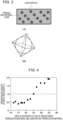
- Fig. 3(A) is a view schematically illustrating the ferrous raw material layer and coke particles mixed in the ferrous raw material layer
- Fig. 3(B) is a view schematically illustrating the shape of a coke particle mixed in the ferrous raw material layer.
- the area of boundary S mix between the ferrous raw material and the coke particles mixed in the ferrous raw material layer was calculated using the equations (2) and (3) below assuming that the coke particles mixed in the ferrous raw material layer were regular octahedrons as illustrated in Fig. 3(B) .
- a is the length (m) of one side of the regular octahedron
- W c is the mass (tons/charge) of the coke mixed per ferrous raw material layer in the furnace)
- ⁇ c is the apparent density (kg/m 3 ) of the coke
- d is the particle size (m) of the coke that is mixed.
- the apparent density ⁇ c of the coke was measured by the immersion method based on the mass per unit volume including voids in the particles.
- the particle size d of the coke mixed was the average particle size of the coke sampled from the mixed burden layer.
- W Iron is the mass (tons/charge) of the ferrous raw material per ferrous raw material layer in the furnace.
- the area of boundary S unit between the ferrous raw material and the coke per unit ferrous raw material is a quotient of the area of boundary S total divided by W Iron .
- the area of boundary S total includes the area of boundary between the lower face of the ferrous raw material layer and the upper face of the coke layer, and the area of boundary between the upper face of the ferrous raw material layer and the lower face of the coke layer.
- the coke particles that are mixed into the ferrous raw material layer at the time of charging are regarded as regular octahedrons, and the surface area of the regular octahedrons corresponding to the number of the coke particles is calculated as the area of boundary between the ferrous raw material and the coke particles. This area of boundary is also included in the area of boundary S total .
- the raw materials were charged under conventional operation conditions while generating a high-concentration reducing gas in a raceway in the furnace.
- the area of boundary S unit between the ferrous raw material and the coke per unit ferrous raw material was approximately 14 m 2 /ton or ore.
- the amount of melt drops in the cohesive zone decreased to about one-tenth of that in the conventional tests and the gas permeability was deteriorated to a level where stable test was no longer feasible. This indicates that the raw material-charging conditions require resetting to fit for a blast furnace operation that generates a high-concentration reducing gas in a raceway in the furnace.
- the amount of metal iron drops was determined by recovering the melt that had dropped during the test after the experiment, separating the metal iron from the slag, and measuring the weight of the metal iron with a weighing machine.
- the gas permeability resistance index KS was determined as an integral value of gas permeability resistance K (1/m) calculated based on the pressure loss measured in a region inside the furnace where the temperature was 1000°C or above, and properties estimated from the operation conditions.
- K ⁇ P / H / ⁇ gas 0.7 ⁇ ⁇ gas 0.3 ⁇ v gas 1.7
- ⁇ P is the pressure loss (Pa)
- H is the thickness (m) of the packed bed in the furnace
- ⁇ gas is the gas density (kg/m 3 )
- ⁇ gas is the gas viscosity (Pa ⁇ s)
- v gas is the gas flow velocity (m/s).
- ⁇ P is obtained by calculating the difference between the pressures measured with pressure gauges installed at the tuyere and on a furnace wall of an upper part of the test furnace (in the space above the packed bed).
- H is determined by measuring the position of the surface of the packed bed with a measuring jig having been inserted through a hole perforated in an upper portion of the test furnace, and calculating the distance in the height direction between the position of the surface of the packed bed and the position where the tuyere is located.
- the position of the surface of the packed bed may be measured with a laser rangefinder.
- ⁇ gas can be calculated from the type of the gas component introduced from the tuyere, the temperature inside the furnace, and the pressure inside the furnace.
- ⁇ gas can be calculated from the type of the gas component introduced from the tuyere, and the temperature inside the furnace.
- v gas can be calculated from the flow rate of the gas introduced from the tuyere, the temperature inside the furnace, and the pressure inside the furnace.
- the temperature inside the furnace is the average of temperatures measured with a plurality of thermometers installed at positions on the furnace wall corresponding to the packed bed.
- the pressure inside the furnace is the average of pressures measured with a plurality of pressure gauges installed at positions on the furnace wall corresponding to the packed bed.
- the pressure inside the furnace may be the average of the pressure at the tuyere used to calculate ⁇ P and the pressure at the upper portion of the packed bed.
- Tmax is the maximum temperature in the measurement of the pressure loss in the furnace and is approximately 1500 to 1650°C, although variable every time the measurement is performed.
- Fig. 4 is a graph illustrating a relationship between the amount of metal iron drops and the area of boundary S unit between the ferrous raw material and the coke per unit ferrous raw material.
- the abscissa in Fig. 4 is the area of boundary (m 2 /ton of ore) between the ferrous raw material and the coke per unit ferrous raw material, and the ordinate is the dimensionless amount (-) of metal drops.
- the dimensionless amount of metal drops is the dimensionless amount of metal iron drops relative to 1.0 of the amount of metal iron drops when the area of boundary S unit per unit ferrous raw material is 25 m 2 /ton of ore.
- the unit (-) means dimensionless.
- Fig. 5 is a graph illustrating a relationship between the gas permeability resistance index KS and the area of boundary S unit between the ferrous raw material and the coke per unit ferrous raw material.
- the abscissa in Fig. 5 is the area of boundary (m 2 /ton of ore) between the ferrous raw material and the coke per unit ferrous raw material, and the ordinate is the gas permeability resistance index KS (10 5 °C/m).
- the gas permeability resistance index KS fell to or below the target 2000 owing to the increase in the amount of metal iron drops.
- the target value of the gas permeability resistance index KS namely, 2000, is a threshold for the feasibility of continuous stable testing.
- stable testing means that the surface height of the packed bed descends uniformly over time and the test is free from troubles, such as gas channeling.
- the blast furnace operation method has been developed based on the above test results.
- the blast furnace operation method is a method of operating a blast furnace while charging a ferrous raw material and coke from a blast furnace top, and injecting from a blast furnace tuyere a gas that generates a high-concentration reducing gas in the raceway in the furnace; and includes controlling the area of boundary S unit between the ferrous raw material and the coke per unit ferrous raw material to a predetermined range.
- the area of boundary S unit between the ferrous raw material and the coke per unit ferrous raw material be controlled to 25 m 2 /ton of ore or more. In this manner, a sufficient amount of metal iron drops can be obtained and the blast furnace can be operated stably. If, on the other hand, the area of boundary S unit between the ferrous raw material and the coke per unit ferrous raw material is less than 25 m 2 /ton of ore, a sufficient amount of metal iron drops cannot be obtained and the gas permeability resistance index KS is increased.
- the area of boundary S unit is increased by increasing the mass W c of the coke mixed per ferrous raw material layer in the furnace, or by decreasing the mass W Iron of the ferrous raw material per ferrous raw material layer in the furnace.
- increasing the mass W c of the coke mixed per ferrous raw material layer in the furnace is accompanied by decreasing the amount of the coke charged into the coke layer in order to keep the ratio of the coke to the ferrous raw material constant.
- the coke layer is reduced in thickness.
- the mass W Iron of the ferrous raw material per ferrous raw material layer in the furnace is decreased, the ferrous raw material layer is reduced in thickness.
- the area of boundary S unit be controlled to 53.1 m 2 /ton of ore or less.
- the high-concentration reducing gas is preferably such that the volume of H 2 gas (including hydrogen in hydrocarbons) in the high-concentration reducing gas is in the range of 0 to 500 Nm 3 /ton of molten pig iron. In this case, it is possible to prevent the decrease in in-furnace temperature and the decrease in reduction reaction rate. If, on the other hand, the volume of H 2 gas in the high-concentration reducing gas is more than 500 Nm 3 /ton of molten pig iron, the in-furnace temperature is disadvantageously lowered to give rise to a decrease in reduction reaction rate. When H 2 gas alone is injected, it is preferable that the H 2 gas be heated before blowing in order to maintain the raceway temperature within an operable range.
- the blast furnace operation method charges a ferrous raw material and coke from the furnace top while controlling the area of boundary S unit between these materials per unit ferrous raw material to a predetermined range.
- This control promotes the carburization of metal iron that is produced and lowers the melting point of the metal iron, thus allowing the metal iron to exhibit appropriate liquid permeability through the cohesive zone and the dripping zone in the blast furnace.
- the gas permeability in the blast furnace can be maintained in an operable range, and the blast furnace can be operated stably.
- a blast furnace operation test was performed in which a ferrous raw material and coke were alternately charged from the top of a large blast furnace and a high-concentration reducing gas was generated in a raceway in the furnace.
- the area of boundary S unit per unit ferrous raw material between the ferrous raw material and the coke charged from the furnace top was changed while keeping constant the mass of the ferrous raw material and the mass of the coke raw material.
- Table 1 Items Units INV. EX. 1 INV. EX. 2 COMP. EX.
Landscapes
- Engineering & Computer Science (AREA)
- Chemical & Material Sciences (AREA)
- Manufacturing & Machinery (AREA)
- Materials Engineering (AREA)
- Metallurgy (AREA)
- Organic Chemistry (AREA)
- Manufacture Of Iron (AREA)
Abstract
Description
- The present invention relates to a method of operating a blast furnace while generating a high-concentration reducing gas in a raceway in the blast furnace, and more particularly to a blast furnace operation method that enhances the liquid permeability of metal iron through a cohesive zone and a dripping zone in a blast furnace, and the gas permeability through the blast furnace.
- In recent years, there have been growing efforts to reduce the emissions of CO2 gas (carbon dioxide gas) that is one of the greenhouse gases. Blast furnace iron manufacturing involves carbon materials as reducing agents and thus generates large amounts of CO2 gas. Thus, the steel industry is one of the major CO2 emitting industries and must respond to the social demands for cutting the CO2 gas emissions. Specifically, it is urgent to further decrease the ratio of coal-derived reducing agents in the blast furnace operation. The ratio of coal-derived reducing agents is the total mass of coal-derived coke and coal-derived reducing gas required to produce 1 ton of molten pig iron.
- Reducing agents have a role to generate heat in the furnace and thereby raise the temperature of the burden, and a role to reduce the ferrous raw material in the furnace, namely, iron ore, sintered iron ore, and iron ore pellets. In order to lower the reducing agent ratio and thereby to cut the CO2 emissions, it is necessary to increase the reduction efficiency of the reducing agent while maintaining the amount of heat in the furnace.
- Hydrogen has attracted attention as a reducing agent for the purpose of cutting CO2 emissions. The reduction of iron ore with hydrogen is an endothermic reaction, but the endothermic amount is smaller than that in the direct reduction reaction (reaction formula: FeO + C → Fe + CO). Furthermore, hydrogen outperforms CO gas in reduction rate. Therefore, the CO2 emissions can be reduced and the reduction efficiency can be enhanced at the same time by the blowing of hydrogen-based gas into the blast furnace.
- Stable operation of a blast furnace critically relies on the gas permeability through the blast furnace cohesive zone in which the ferrous raw material is fused. However, the gas permeability in a blast furnace is not clearly understood in blast furnace operations where a high-concentration reducing gas is generated in a raceway in the blast furnace, and in blast furnace operations in which the reducing gas concentration in the furnace is higher than in the conventional operation and the reduction reaction rate is high.
- Hydrogen reduces the ferrous raw material with a higher reduction ratio than CO gas. Thus, raw material charging conditions that ensure appropriate liquid permeability of metal iron (metal iron produced by reduction) and appropriate gas permeability need to be established for blast furnace operation that involves a high reduction ratio.
- Conventional techniques for solving problems similar to those described above are disclosed in
Patent Literatures -
Patent Literature 1 discloses a burden distribution controlling method that achieves stable blast furnace operation by reliably and accurately controlling the charging pattern of the burden along the radial direction of the furnace throat so that the ore layer/coke layer relative thickness ratio in a peripheral region in the blast furnace will be 0.50 to 0.70. - In a blast furnace operation in which 180 kg or more of pulverized coal per ton of molten pig iron is injected from the tuyere,
Patent Literature 2 discloses a blast furnace operation method that charges coke and iron ore from the top of the furnace so that the ratio of the coke layer thickness Lc to the burden layer thickness that combines the coke layer thickness Lc and the ore layer thickness Lo will satisfy predetermined values in regions divided along the furnace radial direction. According toPatent Literature 2, the technique can decrease the pressure loss in the upper part of the burden layer in the blast furnace, can maintain good gas permeability in the furnace, and enables stable operation with a high volume of pulverized coal injection. -
- PTL 1:
Japanese Unexamined Patent Application Publication No. 2000-256712 - PTL 2:
Japanese Unexamined Patent Application Publication No. 2002-129211 - However, these conventional techniques are directed to operation under conditions where the reduction ratio of the ferrous raw material is low. When the reduction ratio of the ferrous raw material is increased by generating a high-concentration reducing gas in a raceway in the blast furnace, the liquid permeability of metal iron is deteriorated and the gas permeability through the cohesive zone is lowered. Unfortunately, the above conventional techniques are not effective for solving such a blast furnace operation problem.
- Specifically, the ferrous raw material is reduced in a promoted manner from a low temperature compared to the conventional operation and reaches an increased reduction ratio when a high-concentration reducing gas is generated in a raceway in the furnace within the range of region A in
Fig. 1 (Fig. 1 will be described later) (the range including H2 gas = 0 to 100 vol%, N2 gas = 0 to 71 vol%, and CO gas = 0 to 100 vol%). Thus, more metal iron is produced in the blast furnace. - The melting point of iron (Fe) is 1538°C and is higher than the melting point of FeO, 1377°C. For this reason, an operation that charges raw materials in the conventional manner encounters a problem in which the liquid permeability of metal iron is low and the metal iron that should drop into the hearth remains in voids of the coke layers. This increases the gas permeability resistance in the blast furnace and gives rise to a risk of gas channeling.
- The present invention has been made in view of the circumstances discussed above. In a blast furnace operation that generates a high-concentration reducing gas in a raceway in the furnace, an object of the present invention is to provide a blast furnace operation method that can maintain appropriate liquid permeability of metal iron through the cohesive zone and the dripping zone in the blast furnace and can control the gas permeability in the blast furnace within an operable range.
- The present inventors carried out extensive studies directed to solving the problems described above. The finding is that in a blast furnace operation that generates a high-concentration reducing gas in a raceway in the blast furnace, the area of boundary between the ferrous raw material and the coke is controlled so as to increase the carburized area of the coke carbon with respect to the metal iron produced in the furnace, and thereby lowering of the melting point of the metal iron by the carburization is promoted. The present inventors have found that the above control allows for good liquid permeability of metal iron through the cohesive zone and the dripping zone in the blast furnace and also ensures good gas permeability in the blast furnace. The present invention has been completed based on the above findings. A gist of the present invention is as follows.
-
- [1] A blast furnace operation method of operating a blast furnace while alternately charging a ferrous raw material and coke from a blast furnace top, and injecting from a blast furnace tuyere a gas that generates a high-concentration reducing gas in a raceway in the blast furnace, the method including controlling the area of boundary between the ferrous raw material and the coke per unit ferrous raw material to a predetermined range.
- [2] The blast furnace operation method according to [1], wherein the area of boundary per unit ferrous raw material is the total of the area of boundary between a ferrous raw material layer and a coke layer per unit ferrous raw material plus the area of boundary between the ferrous raw material and coke particles mixed in the ferrous raw material layer.
- [3] The blast furnace operation method according to [2], wherein the area of boundary per unit ferrous raw material is controlled to 25 m2/ton of ore or more.
- [4] The blast furnace operation method according to [1], wherein the high-concentration reducing gas, when expressed by bosh gas composition, is composed of H2 gas, N2 gas, and CO gas; has a composition of H2 gas, N2 gas, and CO gas within a region enclosed by four points in a H2 gas-N2 gas-CO gas ternary diagram wherein the four points are a point at H2 gas: 0 vol%, N2 gas: 0 vol%, and CO gas: 100 vol%, a point at H2 gas: 100 vol%, N2 gas: 0 vol%, and CO gas: 0 vol%, a point at H2 gas: 29 vol%, N2 gas: 71 vol%, and CO gas: 0 vol%, and a point at H2 gas: 0 vol%, N2 gas: 37 vol%, and CO gas: 63 vol%; and includes H2 gas in the range of 0 to 100 vol%, N2 gas in the range of 0 to 71 vol%, and CO gas in the range of 0 to 100 vol%.
- [5] The blast furnace operation method according to [2], wherein the high-concentration reducing gas, when expressed by bosh gas composition, is composed of H2 gas, N2 gas, and CO gas; has a composition of H2 gas, N2 gas, and CO gas within a region enclosed by four points in a H2 gas-N2 gas-CO gas ternary diagram wherein the four points are a point at H2 gas: 0 vol%, N2 gas: 0 vol%, and CO gas: 100 vol%, a point at H2 gas: 100 vol%, N2 gas: 0 vol%, and CO gas: 0 vol%, a point at H2 gas: 29 vol%, N2 gas: 71 vol%, and CO gas: 0 vol%, and a point at H2 gas: 0 vol%, N2 gas: 37 vol%, and CO gas: 63 vol%; and includes H2 gas in the range of 0 to 100 vol%, N2 gas in the range of 0 to 71 vol%, and CO gas in the range of 0 to 100 vol%.
- [6] The blast furnace operation method according to [3], wherein the high-concentration reducing gas, when expressed by bosh gas composition, is composed of H2 gas, N2 gas, and CO gas; has a composition of H2 gas, N2 gas, and CO gas within a region enclosed by four points in a H2 gas-N2 gas-CO gas ternary diagram wherein the four points are a point at H2 gas: 0 vol%, N2 gas: 0 vol%, and CO gas: 100 vol%, a point at H2 gas: 100 vol%, N2 gas: 0 vol%, and CO gas: 0 vol%, a point at H2 gas: 29 vol%, N2 gas: 71 vol%, and CO gas: 0 vol%, and a point at H2 gas: 0 vol%, N2 gas: 37 vol%, and CO gas: 63 vol%; and includes H2 gas in the range of 0 to 100 vol%, N2 gas in the range of 0 to 71 vol%, and CO gas in the range of 0 to 100 vol%.
- [7] The blast furnace operation method according to any one of [1] to [6], wherein the volume of H2 in the high-concentration reducing gas is in the range of 0 to 500 Nm3/ton of molten pig iron.
- In a blast furnace operation that generates a high-concentration reducing gas in a raceway in the furnace, the present invention charges a ferrous raw material and coke from the furnace top while controlling the area of boundary between these materials per unit ferrous raw material to a predetermined range. This control promotes the carburization of metal iron that is produced and lowers the melting point of the metal iron, thus allowing the metal iron to maintain appropriate liquid permeability through the cohesive zone and the dripping zone in the blast furnace. As a result, the gas permeability in the blast furnace can be maintained in an operable range, and the blast furnace can be operated stably.
-
- [
Fig. 1] Fig. 1 is a H2 gas-N2 gas-CO gas ternary diagram that illustrates the range of the bosh gas composition of a high-concentration reducing gas generated in a raceway in the furnace in a blast furnace operation method according to an embodiment. - [
Fig. 2] Fig. 2 is a view schematically illustrating the shapes of ferrous raw material layers and coke layers in a blast furnace. - [
Fig. 3] Fig. 3(A) is a view schematically illustrating a ferrous raw material layer and coke particles mixed in the ferrous raw material layer, andFig. 3(B) is a view schematically illustrating the shape of a coke particle mixed in the ferrous raw material layer. - [
Fig. 4] Fig. 4 is a graph illustrating a relationship between the amount of metal iron drops and the area of boundary Sunit between a ferrous raw material and coke per unit ferrous raw material. - [
Fig. 5] Fig. 5 is a graph illustrating a relationship between the gas permeability resistance index KS and the area of boundary Sunit between a ferrous raw material and coke per unit ferrous raw material. - Hereinafter, an embodiment of the present invention will be described in detail. A blast furnace operation method according to the present embodiment is a method of operating a blast furnace in such a manner that a ferrous raw material and coke are alternately charged from a blast furnace top into the blast furnace to form alternate layers, and a gas is injected from a tuyere disposed at a lower position of the blast furnace and the gas that has been injected from the tuyere into the blast furnace generates a high-concentration reducing gas in the raceway in the blast furnace. For example, the ferrous raw material includes iron ore, sintered iron ore, iron ore pellets, reduced iron, and iron scraps. The types of the ferrous raw material and the coke that are used are not particularly limited, and any ferrous raw materials and cokes used in the conventional blast furnace operations may be suitably used in the present invention.
- The gas for generating a high-concentration reducing gas contains a reductive component that reduces the ferrous raw material in the blast furnace. Here, the reductive component that reduces the ferrous raw material in the blast furnace may be CO gas, H2 gas, or a hydrocarbon gas capable of reducing the ferrous raw material by itself, or may be CO2 gas, H2O gas, or the like that generates a reducing gas through, for example, the reaction with the coke or the decomposition reaction.
-
Fig. 1 is a H2 gas-N2 gas-CO gas ternary diagram that illustrates the range of the gas composition of a high-concentration reducing gas generated in a raceway in the furnace in the blast furnace operation method according to the present embodiment. The high-concentration reducing gas in the present embodiment is a reducing gas that reduces the ferrous raw material with an average reduction ratio of 80% or more when the high-concentration reducing gas is allowed to act on the material at 900°C for 180 minutes. This reducing gas, when expressed by bosh gas composition, is composed of H2 gas, N2 gas, and CO gas; has a composition of H2 gas, N2 gas, and CO gas (with the proviso that H2 gas + N2 gas + CO gas = 100 vol%) within the shaded region A inFig. 1 (the range of the operation according to the present invention); and includes H2 gas in the range of 0 to 100 vol%, N2 gas in the range of 0 to 71 vol%, and CO gas in the range of 0 to 100 vol%. - In the H2 gas-N2 gas-CO gas ternary diagram, the region A is enclosed by four points including point O (H2 gas: 0 vol%, N2 gas: 0 vol%, CO gas: 100 vol%), point P (H2 gas: 100 vol%, N2 gas: 0 vol%, CO gas: 0 vol%), point Q (H2 gas: 29 vol%, N2 gas: 71 vol%, CO gas: 0 vol%), and point R (H2 gas: 0 vol%, N2 gas: 37 vol%, CO gas: 63 vol%). As a comparison,
Fig. 1 also illustrates the range of the gas composition in conventional general blast furnace operations. - In this region A, the average reduction ratio is 90% or more when the ferrous raw material is reduced at 900°C for 180 minutes in the region enclosed by four points including point O' (H2 gas: 0 vol%, N2 gas: 0 vol%, CO gas: 100 vol%), point P' (H2 gas: 100 vol%, N2 gas: 0 vol%, CO gas: 0 vol%), point Q' (H2 gas: 43 vol%, N2 gas: 57 vol%, CO gas: 0 vol%), and point R' (H2 gas: 0 vol%, N2 gas: 14 vol%, CO gas: 86 vol%). Thus, the amount of FeO in the slag components in the cohesive zone in the furnace is significantly low. When a high-concentration reducing gas falling in this composition range is generated in a raceway in the furnace, the control of the area of boundary between the ferrous raw material and the coke per unit ferrous raw material to the predetermined range produces greater effects by maintaining appropriate liquid permeability of the metal iron.
- The present inventors conducted a test in which a high-concentration reducing gas was generated in a raceway in a 1/4 scale small test furnace simulating a blast furnace. In the test, the relationship was investigated between the area of boundary between the ferrous raw material and the coke in the cohesive zone and the dripping zone in the furnace, and the amount of metal iron drops (the metal produced by reduction). Here, the area of boundary between the ferrous raw material and the coke is the area of boundary Stotal that combines the area of boundary S between a ferrous raw material layer and a coke layer, and the area of boundary Smix between the ferrous raw material and the coke particles mixed in the ferrous raw material layer (Stotal = S + Smix).
-
Fig. 2 is a view schematically illustrating the shapes of the ferrous raw material layers and the coke layers in the furnace. As illustrated inFig. 2 , the observation confirmed that the ferrous raw material layers and the coke layers descended inside the blast furnace while remaining layered. In this case, the boundary between the ferrous raw material layer and the coke layer occurs between the lower face of the ferrous raw material layer and the upper face of the coke layer (boundary 1 inFig. 2 ) and between the upper face of the ferrous raw material layer and the lower face of the coke layer (boundary 2 inFig. 2 ). Assuming that theboundary 1 and theboundary 2 had the same area, the area of boundary S between the ferrous raw material layer and the coke layer was calculated using the equation (1) below.
[Math. 1]
- In the equation (1), D is the furnace diameter (m) of the test furnace, θ is the inclination angle (°) of the burden in the furnace (the ferrous raw material layers and the coke layers) with respect to a horizontal line, and π is the circumference ratio. For the furnace diameter D, the furnace belly diameter obtained from the design drawing of the test furnace was used. For the inclination angle θ, a value measured at the lumpy zone in the furnace was used. When the boundary between the ferrous raw material layer and the coke layer cannot be approximated by a straight line, for example, the boundary in the radial direction is divided into multiple sections that can be each approximated by a straight line, and the inclination angles of the sections are measured and averaged to determine the inclination angle θ.
-
Fig. 3(A) is a view schematically illustrating the ferrous raw material layer and coke particles mixed in the ferrous raw material layer, andFig. 3(B) is a view schematically illustrating the shape of a coke particle mixed in the ferrous raw material layer. The area of boundary Smix between the ferrous raw material and the coke particles mixed in the ferrous raw material layer was calculated using the equations (2) and (3) below assuming that the coke particles mixed in the ferrous raw material layer were regular octahedrons as illustrated inFig. 3(B) .
- In the equations (2) and (3), a is the length (m) of one side of the regular octahedron; Wc is the mass (tons/charge) of the coke mixed per ferrous raw material layer in the furnace); ρc is the apparent density (kg/m3) of the coke; and d is the particle size (m) of the coke that is mixed. The apparent density ρc of the coke was measured by the immersion method based on the mass per unit volume including voids in the particles. The particle size d of the coke mixed was the average particle size of the coke sampled from the mixed burden layer.
- The area of boundary Sunit between the ferrous raw material and the coke per unit ferrous raw material is expressed by the equation (4) below.
[Math. 3]
- In the equation (4), WIron is the mass (tons/charge) of the ferrous raw material per ferrous raw material layer in the furnace.
- The area of boundary Sunit between the ferrous raw material and the coke per unit ferrous raw material is a quotient of the area of boundary Stotal divided by WIron. The area of boundary Stotal includes the area of boundary between the lower face of the ferrous raw material layer and the upper face of the coke layer, and the area of boundary between the upper face of the ferrous raw material layer and the lower face of the coke layer. Furthermore, the coke particles that are mixed into the ferrous raw material layer at the time of charging are regarded as regular octahedrons, and the surface area of the regular octahedrons corresponding to the number of the coke particles is calculated as the area of boundary between the ferrous raw material and the coke particles. This area of boundary is also included in the area of boundary Stotal.
- In the small test furnace, the raw materials were charged under conventional operation conditions while generating a high-concentration reducing gas in a raceway in the furnace. The area of boundary Sunit between the ferrous raw material and the coke per unit ferrous raw material was approximately 14 m2/ton or ore. Under these raw material-charging conditions, the amount of melt drops in the cohesive zone decreased to about one-tenth of that in the conventional tests and the gas permeability was deteriorated to a level where stable test was no longer feasible. This indicates that the raw material-charging conditions require resetting to fit for a blast furnace operation that generates a high-concentration reducing gas in a raceway in the furnace.
- Based on the knowledge that the enhancement in liquid permeability of metal iron critically relies on increasing the area of carburization on the metal iron produced by reduction in the blast furnace, a test was conducted in which a high-concentration reducing gas was generated in a raceway in the small test furnace while changing the area of boundary Sunit between the ferrous raw material and the coke per unit ferrous raw material. In the test, the area of boundary Sunit between the ferrous raw material and the coke per unit ferrous raw material was changed within the range of 12 to 35 m2/ton of ore, and the influence of the area of boundary Sunit per unit ferrous raw material on the amount of metal iron drops and the gas permeability resistance index KS was studied.
- The amount of metal iron drops was determined by recovering the melt that had dropped during the test after the experiment, separating the metal iron from the slag, and measuring the weight of the metal iron with a weighing machine. The gas permeability resistance index KS was determined as an integral value of gas permeability resistance K (1/m) calculated based on the pressure loss measured in a region inside the furnace where the temperature was 1000°C or above, and properties estimated from the operation conditions.
- The gas permeability resistance K (1/m) is calculated from the equation (5) below.

- Here, ΔP is the pressure loss (Pa), H is the thickness (m) of the packed bed in the furnace, ρgas is the gas density (kg/m3), µgas is the gas viscosity (Pa·s), and vgas is the gas flow velocity (m/s). ΔP is obtained by calculating the difference between the pressures measured with pressure gauges installed at the tuyere and on a furnace wall of an upper part of the test furnace (in the space above the packed bed). For example, H is determined by measuring the position of the surface of the packed bed with a measuring jig having been inserted through a hole perforated in an upper portion of the test furnace, and calculating the distance in the height direction between the position of the surface of the packed bed and the position where the tuyere is located. The position of the surface of the packed bed may be measured with a laser rangefinder. ρgas can be calculated from the type of the gas component introduced from the tuyere, the temperature inside the furnace, and the pressure inside the furnace. µgas can be calculated from the type of the gas component introduced from the tuyere, and the temperature inside the furnace. vgas can be calculated from the flow rate of the gas introduced from the tuyere, the temperature inside the furnace, and the pressure inside the furnace. Here, the temperature inside the furnace is the average of temperatures measured with a plurality of thermometers installed at positions on the furnace wall corresponding to the packed bed. Similarly, the pressure inside the furnace is the average of pressures measured with a plurality of pressure gauges installed at positions on the furnace wall corresponding to the packed bed. The pressure inside the furnace may be the average of the pressure at the tuyere used to calculate ΔP and the pressure at the upper portion of the packed bed.
- The gas permeability resistance index KS is calculated using the equation (6) below.
[Math. 4]
- In the equation (6), Tmax is the maximum temperature in the measurement of the pressure loss in the furnace and is approximately 1500 to 1650°C, although variable every time the measurement is performed.
-
Fig. 4 is a graph illustrating a relationship between the amount of metal iron drops and the area of boundary Sunit between the ferrous raw material and the coke per unit ferrous raw material. The abscissa inFig. 4 is the area of boundary (m2/ton of ore) between the ferrous raw material and the coke per unit ferrous raw material, and the ordinate is the dimensionless amount (-) of metal drops. The dimensionless amount of metal drops is the dimensionless amount of metal iron drops relative to 1.0 of the amount of metal iron drops when the area of boundary Sunit per unit ferrous raw material is 25 m2/ton of ore. The unit (-) means dimensionless. -
Fig. 5 is a graph illustrating a relationship between the gas permeability resistance index KS and the area of boundary Sunit between the ferrous raw material and the coke per unit ferrous raw material. The abscissa inFig. 5 is the area of boundary (m2/ton of ore) between the ferrous raw material and the coke per unit ferrous raw material, and the ordinate is the gas permeability resistance index KS (105°C/m). - As illustrated in
Fig. 4 , it was shown that the amount of metal iron drops increased when the area of boundary Sunit between the ferrous raw material and the coke per unit ferrous raw material was 25 m2/ton of ore or more. This is probably because the metal iron produced by reduction has more opportunities to be in contact with carbon in the coke, and the metal iron is carburized and comes to have a lowered melting point. - When the area of boundary Sunit between the ferrous raw material and the coke per unit ferrous raw material was 25 m2/ton of ore or more, as illustrated in
Fig. 5 , the gas permeability resistance index KS fell to or below thetarget 2000 owing to the increase in the amount of metal iron drops. The target value of the gas permeability resistance index KS, namely, 2000, is a threshold for the feasibility of continuous stable testing. The term stable testing means that the surface height of the packed bed descends uniformly over time and the test is free from troubles, such as gas channeling. - These results have shown that a test in which a high-concentration reducing gas is generated in a raceway in the furnace can be performed stably by controlling the area of boundary Sunit between the ferrous raw material and the coke per unit ferrous raw material to 25 m2/ton of ore or more.
- The blast furnace operation method according to the present embodiment has been developed based on the above test results. The blast furnace operation method is a method of operating a blast furnace while charging a ferrous raw material and coke from a blast furnace top, and injecting from a blast furnace tuyere a gas that generates a high-concentration reducing gas in the raceway in the furnace; and includes controlling the area of boundary Sunit between the ferrous raw material and the coke per unit ferrous raw material to a predetermined range.
- Here, it is preferable that the area of boundary Sunit between the ferrous raw material and the coke per unit ferrous raw material be controlled to 25 m2/ton of ore or more. In this manner, a sufficient amount of metal iron drops can be obtained and the blast furnace can be operated stably. If, on the other hand, the area of boundary Sunit between the ferrous raw material and the coke per unit ferrous raw material is less than 25 m2/ton of ore, a sufficient amount of metal iron drops cannot be obtained and the gas permeability resistance index KS is increased.
- The area of boundary Sunit is increased by increasing the mass Wc of the coke mixed per ferrous raw material layer in the furnace, or by decreasing the mass WIron of the ferrous raw material per ferrous raw material layer in the furnace. In blast furnace operation, normally, increasing the mass Wc of the coke mixed per ferrous raw material layer in the furnace is accompanied by decreasing the amount of the coke charged into the coke layer in order to keep the ratio of the coke to the ferrous raw material constant. As a result, the coke layer is reduced in thickness. When, on the other hand, the mass WIron of the ferrous raw material per ferrous raw material layer in the furnace is decreased, the ferrous raw material layer is reduced in thickness. Because the raw materials do not necessarily descend at a constant rate in the radial direction of the blast furnace, excessive thinning of the coke layers or the ferrous raw material layers may lead to collapse of the layered structure of the coke layers and the ferrous raw material layers. In order to ensure that the ferrous raw material and the coke that have been alternately charged in the blast furnace to form a layered structure will descend in the blast furnace while remaining layered, it is preferable that the area of boundary Sunit be controlled to 53.1 m2/ton of ore or less.
- The high-concentration reducing gas is preferably such that the volume of H2 gas (including hydrogen in hydrocarbons) in the high-concentration reducing gas is in the range of 0 to 500 Nm3/ton of molten pig iron. In this case, it is possible to prevent the decrease in in-furnace temperature and the decrease in reduction reaction rate. If, on the other hand, the volume of H2 gas in the high-concentration reducing gas is more than 500 Nm3/ton of molten pig iron, the in-furnace temperature is disadvantageously lowered to give rise to a decrease in reduction reaction rate. When H2 gas alone is injected, it is preferable that the H2 gas be heated before blowing in order to maintain the raceway temperature within an operable range.
- In a blast furnace operation that generates a high-concentration reducing gas in a raceway in the furnace, as described hereinabove, the blast furnace operation method according to the present embodiment charges a ferrous raw material and coke from the furnace top while controlling the area of boundary Sunit between these materials per unit ferrous raw material to a predetermined range. This control promotes the carburization of metal iron that is produced and lowers the melting point of the metal iron, thus allowing the metal iron to exhibit appropriate liquid permeability through the cohesive zone and the dripping zone in the blast furnace. As a result, the gas permeability in the blast furnace can be maintained in an operable range, and the blast furnace can be operated stably.
- A blast furnace operation test was performed in which a ferrous raw material and coke were alternately charged from the top of a large blast furnace and a high-concentration reducing gas was generated in a raceway in the furnace. The area of boundary Sunit per unit ferrous raw material between the ferrous raw material and the coke charged from the furnace top was changed while keeping constant the mass of the ferrous raw material and the mass of the coke raw material. The operation conditions and the test results are described in Table 1 below.
[Table 1] Items Units INV. EX. 1 INV. EX. 2 COMP. EX. 1 Furnace body Furnace diameter m 15 15 15 Conditions of charging of iron-source raw material and coke Inclination angle θ ∘ 22 22 22 Mass WIron of ferrous raw material tons/charge 178 178 178 Mass of coke raw material tons/charge 28.2 28.2 28.2 Apparent density ρc of coke kg/m3 800 800 800 Particle size d of coke mixed mm 25 25 25 Mass Wc of coke mixed tons/charge 13.5 9.5 6 Area of boundary Sunit m2/ton of ore 34.4 25.0 16.9 Bosh gas CO gas vol% 62 62 62 H2 gas vol% 38 38 38 N2 gas vol% 0 0 0 H2 volume Nm3/ton of molten pig iron 430 430 430 Operation data Methane ratio*1 Kg/ton of molten pig iron 155 155 155 Unit consumption of blast volume Nm3/ton of molten pig iron 350 350 350 Oxygen enrichment % (dry) 100 100 100 Operation results Metal iron liquid permeability - Good Good Poor Gas permeability - Good Good Poor *1: The methane ratio is the amount of methane injected per ton of molten pig iron. - In INVENTIVE EXAMPLES 1 and 2, the ferrous raw material and the coke were charged from the furnace top with control of the area of boundary Sunit per unit ferrous raw material to the range of the present invention. As described in Table 1, it was confirmed that these examples realized good metal iron liquid permeability and good gas permeability and made stable operation possible. In COMPARATIVE EXAMPLE 1, the ferrous raw material and the coke that were charged from the furnace top failed to satisfy the inventive range of the area of boundary Sunit per unit ferrous raw material. As a result, sufficient metal iron liquid permeability could not be obtained and the gas permeability was also poor.
Claims (7)
- A blast furnace operation method of operating a blast furnace while alternately charging a ferrous raw material and coke from a blast furnace top, and injecting from a blast furnace tuyere a gas that generates a high-concentration reducing gas in a raceway in the blast furnace, the method comprising controlling the area of boundary between the ferrous raw material and the coke per unit ferrous raw material to a predetermined range.
- The blast furnace operation method according to claim 1, wherein the area of boundary per unit ferrous raw material is the total of the area of boundary between a ferrous raw material layer and a coke layer per unit ferrous raw material plus the area of boundary between the ferrous raw material and coke particles mixed in the ferrous raw material layer.
- The blast furnace operation method according to claim 2, wherein the area of boundary per unit ferrous raw material is controlled to 25 m2/ton of ore or more.
- The blast furnace operation method according to claim 1, wherein the high-concentration reducing gas, when expressed by bosh gas composition, is composed of H2 gas, N2 gas, and CO gas; has a composition of H2 gas, N2 gas, and CO gas within a region enclosed by four points in a H2 gas-N2 gas-CO gas ternary diagram wherein the four points are a point at H2 gas: 0 vol%, N2 gas: 0 vol%, and CO gas: 100 vol%, a point at H2 gas: 100 vol%, N2 gas: 0 vol%, and CO gas: 0 vol%, a point at H2 gas: 29 vol%, N2 gas: 71 vol%, and CO gas: 0 vol%, and a point at H2 gas: 0 vol%, N2 gas: 37 vol%, and CO gas: 63 vol%; and includes H2 gas in the range of 0 to 100 vol%, N2 gas in the range of 0 to 71 vol%, and CO gas in the range of 0 to 100 vol%.
- The blast furnace operation method according to claim 2, wherein the high-concentration reducing gas, when expressed by bosh gas composition, is composed of H2 gas, N2 gas, and CO gas; has a composition of H2 gas, N2 gas, and CO gas within a region enclosed by four points in a H2 gas-N2 gas-CO gas ternary diagram wherein the four points are a point at H2 gas: 0 vol%, N2 gas: 0 vol%, and CO gas: 100 vol%, a point at H2 gas: 100 vol%, N2 gas: 0 vol%, and CO gas: 0 vol%, a point at H2 gas: 29 vol%, N2 gas: 71 vol%, and CO gas: 0 vol%, and a point at H2 gas: 0 vol%, N2 gas: 37 vol%, and CO gas: 63 vol%; and includes H2 gas in the range of 0 to 100 vol%, N2 gas in the range of 0 to 71 vol%, and CO gas in the range of 0 to 100 vol%.
- The blast furnace operation method according to claim 3, wherein the high-concentration reducing gas, when expressed by bosh gas composition, is composed of H2 gas, N2 gas, and CO gas; has a composition of H2 gas, N2 gas, and CO gas within a region enclosed by four points in a H2 gas-N2 gas-CO gas ternary diagram wherein the four points are a point at H2 gas: 0 vol%, N2 gas: 0 vol%, and CO gas: 100 vol%, a point at H2 gas: 100 vol%, N2 gas: 0 vol%, and CO gas: 0 vol%, a point at H2 gas: 29 vol%, N2 gas: 71 vol%, and CO gas: 0 vol%, and a point at H2 gas: 0 vol%, N2 gas: 37 vol%, and CO gas: 63 vol%; and includes H2 gas in the range of 0 to 100 vol%, N2 gas in the range of 0 to 71 vol%, and CO gas in the range of 0 to 100 vol%.
- The blast furnace operation method according to any one of claims 1 to 6, wherein the volume of H2 in the high-concentration reducing gas is in the range of 0 to 500 Nm3/ton of molten pig iron.
Applications Claiming Priority (2)
| Application Number | Priority Date | Filing Date | Title |
|---|---|---|---|
| JP2022064978 | 2022-04-11 | ||
| PCT/JP2022/046306 WO2023199551A1 (en) | 2022-04-11 | 2022-12-16 | Blast furnace operation method |
Publications (2)
| Publication Number | Publication Date |
|---|---|
| EP4477763A1 true EP4477763A1 (en) | 2024-12-18 |
| EP4477763A4 EP4477763A4 (en) | 2025-05-07 |
Family
ID=88329544
Family Applications (1)
| Application Number | Title | Priority Date | Filing Date |
|---|---|---|---|
| EP22937526.6A Pending EP4477763A4 (en) | 2022-04-11 | 2022-12-16 | BLAST FURNACE OPERATING PROCESS |
Country Status (6)
| Country | Link |
|---|---|
| EP (1) | EP4477763A4 (en) |
| JP (1) | JP7513200B2 (en) |
| KR (1) | KR20240160151A (en) |
| CN (1) | CN118946669A (en) |
| TW (1) | TWI872421B (en) |
| WO (1) | WO2023199551A1 (en) |
Family Cites Families (8)
| Publication number | Priority date | Publication date | Assignee | Title |
|---|---|---|---|---|
| US179475A (en) * | 1876-07-04 | Improvement in treatment of minerals, ores | ||
| JPS60228610A (en) * | 1984-04-26 | 1985-11-13 | Nippon Kokan Kk <Nkk> | Method for operating blast furnace |
| JPS63161104A (en) * | 1986-12-23 | 1988-07-04 | Kawasaki Steel Corp | Method for charging raw material into vertical type furnace |
| JP4157951B2 (en) | 1999-03-08 | 2008-10-01 | 日新製鋼株式会社 | Charge distribution control method for blast furnace throat |
| JP3603776B2 (en) | 2000-10-31 | 2004-12-22 | Jfeスチール株式会社 | Blast furnace operation method |
| JP4697340B2 (en) * | 2009-05-29 | 2011-06-08 | Jfeスチール株式会社 | Blast furnace operation method |
| JP5403027B2 (en) * | 2011-09-27 | 2014-01-29 | Jfeスチール株式会社 | Blast furnace operating method and coke manufacturing method using woody biomass |
| JP2016160494A (en) * | 2015-03-03 | 2016-09-05 | Jfeスチール株式会社 | Blast furnace operation method |
-
2022
- 2022-12-16 JP JP2023516076A patent/JP7513200B2/en active Active
- 2022-12-16 WO PCT/JP2022/046306 patent/WO2023199551A1/en not_active Ceased
- 2022-12-16 EP EP22937526.6A patent/EP4477763A4/en active Pending
- 2022-12-16 CN CN202280094360.5A patent/CN118946669A/en active Pending
- 2022-12-16 KR KR1020247032648A patent/KR20240160151A/en active Pending
- 2022-12-22 TW TW111149331A patent/TWI872421B/en active
Also Published As
| Publication number | Publication date |
|---|---|
| WO2023199551A1 (en) | 2023-10-19 |
| JP7513200B2 (en) | 2024-07-09 |
| JPWO2023199551A1 (en) | 2023-10-19 |
| KR20240160151A (en) | 2024-11-08 |
| CN118946669A (en) | 2024-11-12 |
| TWI872421B (en) | 2025-02-11 |
| EP4477763A4 (en) | 2025-05-07 |
| TW202340483A (en) | 2023-10-16 |
Similar Documents
| Publication | Publication Date | Title |
|---|---|---|
| EP2930249B1 (en) | Method for operating blast furnace and method for producing molten pig iron | |
| CN114787391B (en) | Method for operating blast furnace | |
| EP2450459B1 (en) | Blast-furnace operation method | |
| EP2239344A1 (en) | Self-fluxing pellets for use in a blast furnce and process for the production of the same | |
| EP4353841A1 (en) | Shaft furnace operation method and reduce iron production method | |
| EP2653564A1 (en) | Method for operating blast furnace | |
| EP4407048A2 (en) | Pig iron production method | |
| EP2410065B1 (en) | Blast furnace operation method | |
| WO1996015277A1 (en) | Method of operating blast furnace | |
| EP4477763A1 (en) | Blast furnace operation method | |
| EP4477762A1 (en) | Operation method for blast furnace | |
| EP2202324A1 (en) | Vertical furnace and method of operating the same | |
| EP4056722A1 (en) | Method for producing molten iron using electric furnace | |
| JP3589016B2 (en) | Blast furnace operation method | |
| EP2495339B1 (en) | Method for operating blast furnace | |
| EP4289977A1 (en) | Pig iron production method | |
| JP2023177114A (en) | How to operate a blast furnace | |
| JP2007186759A (en) | Blast furnace operation method | |
| EP4733421A1 (en) | Blast furnace operation method | |
| EP4722394A1 (en) | Blast furnace operating method | |
| EP4545653A1 (en) | Pig iron manufacturing method | |
| JP4093198B2 (en) | Blast furnace operation method | |
| US20240167111A1 (en) | Method for producing pig iron | |
| EP4733422A1 (en) | Method for measuring gas reduction rate, method for operating blast furnace, method for operating direct reduction shaft furnace, and iron raw material | |
| JP2026054777A (en) | Blast furnace operation methods |
Legal Events
| Date | Code | Title | Description |
|---|---|---|---|
| STAA | Information on the status of an ep patent application or granted ep patent |
Free format text: STATUS: THE INTERNATIONAL PUBLICATION HAS BEEN MADE |
|
| PUAI | Public reference made under article 153(3) epc to a published international application that has entered the european phase |
Free format text: ORIGINAL CODE: 0009012 |
|
| STAA | Information on the status of an ep patent application or granted ep patent |
Free format text: STATUS: REQUEST FOR EXAMINATION WAS MADE |
|
| 17P | Request for examination filed |
Effective date: 20240913 |
|
| AK | Designated contracting states |
Kind code of ref document: A1 Designated state(s): AL AT BE BG CH CY CZ DE DK EE ES FI FR GB GR HR HU IE IS IT LI LT LU LV MC ME MK MT NL NO PL PT RO RS SE SI SK SM TR |
|
| A4 | Supplementary search report drawn up and despatched |
Effective date: 20250407 |
|
| RIC1 | Information provided on ipc code assigned before grant |
Ipc: C21B 5/00 20060101AFI20250401BHEP |
|
| DAV | Request for validation of the european patent (deleted) | ||
| DAX | Request for extension of the european patent (deleted) |