EP4477762A1 - Operation method for blast furnace - Google Patents
Operation method for blast furnace Download PDFInfo
- Publication number
- EP4477762A1 EP4477762A1 EP22937525.8A EP22937525A EP4477762A1 EP 4477762 A1 EP4477762 A1 EP 4477762A1 EP 22937525 A EP22937525 A EP 22937525A EP 4477762 A1 EP4477762 A1 EP 4477762A1
- Authority
- EP
- European Patent Office
- Prior art keywords
- gas
- vol
- blast furnace
- raw material
- furnace
- Prior art date
- Legal status (The legal status is an assumption and is not a legal conclusion. Google has not performed a legal analysis and makes no representation as to the accuracy of the status listed.)
- Pending
Links
Images

Classifications
-
- C—CHEMISTRY; METALLURGY
- C21—METALLURGY OF IRON
- C21B—MANUFACTURE OF IRON OR STEEL
- C21B5/00—Making pig-iron in the blast furnace
- C21B5/001—Injecting additional fuel or reducing agents
-
- C—CHEMISTRY; METALLURGY
- C21—METALLURGY OF IRON
- C21B—MANUFACTURE OF IRON OR STEEL
- C21B5/00—Making pig-iron in the blast furnace
-
- C—CHEMISTRY; METALLURGY
- C21—METALLURGY OF IRON
- C21B—MANUFACTURE OF IRON OR STEEL
- C21B5/00—Making pig-iron in the blast furnace
- C21B5/001—Injecting additional fuel or reducing agents
- C21B5/003—Injection of pulverulent coal
-
- C—CHEMISTRY; METALLURGY
- C21—METALLURGY OF IRON
- C21B—MANUFACTURE OF IRON OR STEEL
- C21B5/00—Making pig-iron in the blast furnace
- C21B5/008—Composition or distribution of the charge
-
- C—CHEMISTRY; METALLURGY
- C21—METALLURGY OF IRON
- C21B—MANUFACTURE OF IRON OR STEEL
- C21B5/00—Making pig-iron in the blast furnace
- C21B5/06—Making pig-iron in the blast furnace using top gas in the blast furnace process
-
- C—CHEMISTRY; METALLURGY
- C21—METALLURGY OF IRON
- C21B—MANUFACTURE OF IRON OR STEEL
- C21B7/00—Blast furnaces
- C21B7/16—Tuyéres
- C21B7/163—Blowpipe assembly
-
- C—CHEMISTRY; METALLURGY
- C21—METALLURGY OF IRON
- C21B—MANUFACTURE OF IRON OR STEEL
- C21B5/00—Making pig-iron in the blast furnace
- C21B5/001—Injecting additional fuel or reducing agents
- C21B2005/005—Selection or treatment of the reducing gases
Definitions
- the present invention relates to a method of operating a blast furnace while generating a high-concentration reducing gas in a raceway in the blast furnace, and more particularly to a blast furnace operation method that improves slag properties in a cohesive zone and a dripping zone in a blast furnace and thereby enhances the gas permeability in the blast furnace.
- CO 2 gas carbon dioxide gas
- Blast furnace iron manufacturing involves carbon materials as reducing agents and thus generates large amounts of CO 2 gas.
- the steel industry is one of the major CO 2 emitting industries and must respond to the social demands for cutting the CO 2 gas emissions.
- the ratio of coal-derived reducing agents is the total mass of coal-derived coke and coal-derived reducing gas required to produce 1 ton of molten pig iron.
- Hydrogen has attracted attention as a reducing agent for the purpose of cutting CO 2 emissions.
- the reduction of iron ore with hydrogen is an endothermic reaction, but the endothermic amount is smaller than that in the direct reduction reaction (reaction formula: FeO + C ⁇ Fe + CO).
- reaction formula: FeO + C ⁇ Fe + CO reaction formula: FeO + C ⁇ Fe + CO.
- hydrogen outperforms CO gas in reduction rate. Therefore, the CO 2 emissions can be reduced and the reduction efficiency can be enhanced at the same time by the blowing of hydrogen-based gas into the blast furnace.
- Stable operation of a blast furnace critically relies on the gas permeability through the blast furnace cohesive zone in which the ferrous raw material is fused.
- the gas permeability in a blast furnace is not clearly understood in blast furnace operations where a high-concentration reducing gas is generated in a raceway in the blast furnace, and in blast furnace operations in which the reducing gas concentration in the furnace is higher than in the conventional operation and the reduction reaction rate is high.
- blast furnace slag an oxide mixture composed of, for example, FeO, CaO, Al 2 O 3 , MgO, and SiO 2
- raw materials should be designed so that the viscosity of the blast furnace slag that is produced will be kept low to ensure liquid permeability.
- Patent Literatures 1 to 3 Conventional techniques for solving problems similar to those described above are disclosed in Patent Literatures 1 to 3.
- Patent Literature 3 discloses a blast furnace operation method in which an auxiliary raw material is added in a ratio controlled in accordance with the amount of Al 2 O 3 in usual sintered ore and thereby sintered ore is produced that is enhanced in strength (SI > 92%) and reducibility (RI > 70%).
- an auxiliary raw material is injected from a blast furnace tuyere in an amount corresponding to the difference in the blend ratio of the auxiliary raw material between the sintered ore enhanced in strength and reducibility and the usual sintered ore. This control enables long-term stable operation with a high ore-to-coke ratio.
- these conventional techniques are directed to blast furnace operation that injects an auxiliary raw material, such as SiO 2 powder, an auxiliary fuel containing, for example, CaO and SiO 2 , or pulverized coal through a tuyere.
- the techniques are silent with respect to raw material components that are charged or slag components in blast furnace operation that generates a high-concentration reducing gas in a raceway in the furnace.
- a reducing gas generated in a raceway in the furnace has a very high concentration.
- the ferrous raw material in the furnace is reduced with an increased reduction ratio and the FeO concentration in the slag decreases to a level below the operation ranges described in the above conventional techniques.
- the conventional techniques described above do not consider a case where the FeO components in the slag further decrease.
- the slag permeability is lowered by the decrease in FeO components in the slag and consequently the slag is accumulated in voids in the coke layers to raise the gas permeability resistance in the furnace, thus giving rise to a risk of gas channeling.
- an object of the present invention is to provide a blast furnace operation method that improves slag properties to ensure gas permeability through the cohesive zone and the dripping zone in the blast furnace even after FeO components in slag have decreased.
- a gist of the present invention that solves the problems described above is as follows.
- the present invention controls the gross basicity (mass% CaO/mass% SiO 2 ) of a ferrous raw material and an auxiliary raw material to a predetermined range.
- This control optimizes the viscosity of slag formed in the cohesive zone and the dripping zone in the blast furnace and the slag permeability in the blast furnace is controlled to an operable range.
- the gas permeability in the blast furnace can be maintained in good state, and the blast furnace can be operated stably.
- a blast furnace operation method is a method of operating a blast furnace in such a manner that a ferrous raw material, an auxiliary raw material, and coke are alternately charged from a blast furnace top into the blast furnace to form alternate layers, and a gas is injected from a tuyere disposed at a lower position of the blast furnace and the gas that has been injected from the tuyere into the blast furnace generates a high-concentration reducing gas in the raceway in the blast furnace.
- the ferrous raw material includes iron ore, sintered iron ore, iron ore pellets, reduced iron, and iron scraps.
- the auxiliary raw material includes SiO 2 and/or CaO.
- the types of the ferrous raw material, the auxiliary raw material, and the coke that are used are not particularly limited, and any ferrous raw materials, auxiliary raw materials, and cokes used in the conventional blast furnace operations may be suitably used in the present invention.
- the gas for generating a high-concentration reducing gas contains a reductive component that reduces the ferrous raw material in the blast furnace.
- the reductive component that reduces the ferrous raw material in the blast furnace may be CO gas, H 2 gas, or a hydrocarbon gas capable of reducing the ferrous raw material, or may be CO 2 gas, H 2 O gas, or the like that generates a reducing gas through, for example, the reaction with the coke or the decomposition reaction.
- Fig. 1 is a H 2 gas-N 2 gas-CO gas ternary diagram that illustrates the range of the bosh gas composition of a high-concentration reducing gas generated in a raceway in the furnace in the blast furnace operation method according to the present embodiment.
- the high-concentration reducing gas in the present embodiment is a reducing gas that reduces the ferrous raw material with an average reduction ratio of 80% or more when the high-concentration reducing gas is allowed to act on the material at 900°C for 180 minutes.
- the region A is enclosed by four points including point O (H 2 gas: 0 vol%, N 2 gas: 0 vol%, CO gas: 100 vol%), point P (H 2 gas: 100 vol%, N 2 gas: 0 vol%, CO gas: 0 vol%), point Q (H 2 gas: 29 vol%, N 2 gas: 71 vol%, CO gas: 0 vol%), and point R (H 2 gas: 0 vol%, N 2 gas: 37 vol%, CO gas: 63 vol%).
- point O H 2 gas: 0 vol%, N 2 gas: 0 vol%, CO gas: 100 vol%)
- point P H 2 gas: 100 vol%, N 2 gas: 0 vol%, CO gas: 0 vol%
- point Q H 2 gas: 29 vol%, N 2 gas: 71 vol%, CO gas: 0 vol%)
- point R H 2 gas: 0 vol%, N 2 gas: 37 vol%, CO gas: 63 vol%).
- Fig. 1 also illustrates the range of the gas composition in conventional general blast
- the average reduction ratio is 90% or more when the ferrous raw material is reduced at 900°C for 180 minutes in the region enclosed by four points including point O (H 2 gas: 0 vol%, N 2 gas: 0 vol%, CO gas: 100 vol%), point P (H 2 gas: 100 vol%, N 2 gas: 0 vol%, CO gas: 0 vol%), point Q' (H 2 gas: 43 vol%, N 2 gas: 57 vol%, CO gas: 0 vol%), and point R' (H 2 gas: 0 vol%, N 2 gas: 14 vol%, CO gas: 86 vol%).
- point O H 2 gas: 0 vol%, N 2 gas: 0 vol%, CO gas: 100 vol%)
- point P H 2 gas: 100 vol%, N 2 gas: 0 vol%, CO gas: 0 vol%)
- point Q' H 2 gas: 43 vol%, N 2 gas: 57 vol%, CO gas: 0 vol%)
- point R' H 2 gas: 0 vol%, N 2 gas: 14 vol%,
- the present inventors conducted a test in which a high-concentration reducing gas was generated in a raceway in a 1/4 scale small test furnace simulating a blast furnace and slag components in the cohesive zone and the dripping zone in the furnace were studied.
- Table 1 describes some examples of the chemical compositions of ferrous raw materials used in the small test furnace.
- a ferrous raw material, an auxiliary raw material, and coke were charged in accordance with the operation method described in Patent Literature 2 while generating a high-concentration reducing gas in a raceway in the furnace.
- the gross basicity of the ferrous raw material and the auxiliary raw material was controlled to 2.0.
- the slag components in the cohesive zone in the furnace were calculated to include less than 3.5 mass% FeO components, 25.4 to 28.3 mass% SiO 2 components, 8.6 to 9.2 mass% Al 2 O 3 components, 52.5 to 56.7 mass% CaO components, and 5.3 to 7.3 mass% MgO components.
- the basicity of the slag was as high as about 2.0, and the amount of slag drops decreased to about one-tenth of that in the conventional tests. As a result, the gas permeability was deteriorated to a level where stable test was no longer feasible.
- the present inventors considered that the basicity of the slag produced should be lowered in order to increase the amount of slag drops.
- the present inventors then carried out a test in which a high-concentration reducing gas was generated in a raceway in the furnace while changing the gross basicity of the ferrous raw material and the auxiliary raw material within the range of 0.95 to 2.23. The influence of the gross basicity on the amount of melt drops and the gas permeability resistance index KS was thus studied.
- the amount of melt drops was determined by recovering the melt that had dropped during the test after the experiment, and measuring the total weight of the melt with a weighing machine.
- the gas permeability resistance index KS was determined as an integral value of gas permeability resistance K (1/m) calculated based on the pressure loss measured in a region inside the furnace where the temperature was 1000°C or above, and properties estimated from the operation conditions.
- K ⁇ P/H / ⁇ gas 0.7 ⁇ ⁇ gas 0.3 ⁇ v gas 1.7
- ⁇ P is the pressure loss (Pa)
- H is the thickness (m) of the packed bed in the furnace
- ⁇ gas is the gas density (kg/m 3 )
- ⁇ gas is the gas viscosity (Pa ⁇ s)
- v gas is the gas flow velocity (m/s).
- ⁇ P is obtained by calculating the difference between the pressures measured with pressure gauges installed at the tuyere and on a furnace wall of an upper part of the test furnace (in the space above the packed bed).
- H is determined by measuring the position of the surface of the packed bed with a measuring jig having been inserted through a hole perforated in an upper portion of the test furnace, and calculating the distance in the height direction between the position of the surface of the packed bed and the position where the tuyere is located.
- the position of the surface of the packed bed may be measured with a laser rangefinder.
- ⁇ gas can be calculated from the type of the gas component introduced from the tuyere, the temperature inside the furnace, and the pressure inside the furnace.
- ⁇ gas can be calculated from the type of the gas component introduced from the tuyere, and the temperature inside the furnace.
- v gas can be calculated from the flow rate of the gas introduced from the tuyere, the temperature inside the furnace, and the pressure inside the furnace.
- the temperature inside the furnace is the average of temperatures measured with a plurality of thermometers installed at positions on the furnace wall corresponding to the packed bed.
- the pressure inside the furnace is the average of pressures measured with a plurality of pressure gauges installed at positions on the furnace wall corresponding to the packed bed.
- the pressure inside the furnace may be the average of the pressure at the tuyere used to calculate ⁇ P and the pressure at the upper portion of the packed bed.
- Tmax is the maximum temperature in the measurement of the pressure loss in the furnace and is approximately 1500 to 1650°C, although variable every time the measurement is performed.
- Fig. 2 is a graph illustrating the influence of the gross basicity on the amount of melt drops in the test in which a high-concentration reducing gas was generated in a raceway in the furnace.
- the abscissa in Fig. 2 is the gross basicity (mass% CaO/mass% SiO 2 ) and the ordinate is the amount (g) of melt drops.
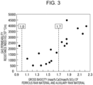
- Fig. 3 is a graph illustrating the influence of the gross basicity on the gas permeability resistance index KS in the test in which a high-concentration reducing gas was generated in a raceway in the furnace.
- the abscissa in Fig. 3 is the gross basicity (mass% CaO/mass% SiO 2 ) and the ordinate is the gas permeability resistance index KS (10 5 °C/m).
- the gas permeability resistance index KS fell to or below the target 2000 when the gross basicity of the ferrous raw material and the auxiliary raw material was in the range of 1.0 to 1.7.
- the target value of the gas permeability resistance index KS namely, 2000, is a threshold for the feasibility of continuous stable testing.
- stable testing means that the surface height of the packed bed descends uniformly over time and the test is free from troubles, such as gas channeling.
- the blast furnace operation method has been developed based on the above test results.
- the blast furnace operation method is a method of operating a blast furnace while charging a ferrous raw material, an auxiliary raw material, and coke from a blast furnace top, and injecting from a blast furnace tuyere a gas that generates a high-concentration reducing gas in the raceway in the blast furnace; and includes controlling the gross basicity of the ferrous raw material and the auxiliary raw material that are charged, to a predetermined range.
- the gross basicity of the ferrous raw material and the auxiliary raw material that are charged be controlled to 1.0 or more and 1.7 or less. In this manner, melt drip characteristics and gas permeability at a lower part of the blast furnace can be enhanced. If the gross basicity of the ferrous raw material and the auxiliary raw material is less than 1.0, or if the gross basicity of the ferrous raw material and the auxiliary raw material is more than 1.7, the slag viscosity is disadvantageously increased beyond a stable operation range in both cases.
- the gross basicity of the ferrous raw material and the auxiliary raw material that are charged is more preferably controlled to 1.1 or more and 1.7 or less, and still more preferably controlled to 1.4 or more and 1.5 or less. This control further reduces the slag viscosity, and melt drip characteristics and gas permeability can be further enhanced.
- the raw materials are preferably adjusted so that the amount of slag will be 400 kg or less per ton of molten pig iron. Controlling the amount of slag to 400 kg or less per ton of molten pig iron can eliminate or reduce the lowering in gas permeability due to the increase in the amount of melts occurring from a low temperature range.
- the high-concentration reducing gas is preferably such that the volume of H 2 gas (including hydrogen in hydrocarbons) in the high-concentration reducing gas is in the range of 0 to 500 Nm 3 /ton of molten pig iron. In this case, it is possible to eliminate or reduce the decrease in in-furnace temperature and the decrease in reduction reaction rate. If, on the other hand, the volume of H 2 gas in the high-concentration reducing gas is more than 500 Nm 3 /ton of molten pig iron, the in-furnace temperature is disadvantageously lowered to give rise to a decrease in reduction reaction rate. When H 2 gas alone is injected, it is preferable that the H 2 gas be heated before blowing in order to maintain the raceway temperature within an operable range.
- the blast furnace operation method charges a ferrous raw material and an auxiliary raw material while controlling the gross basicity of the ferrous raw material and the auxiliary raw material to a predetermined range.
- This control optimizes the viscosity of slag formed in the cohesive zone and the dripping zone in the blast furnace and the slag permeability in the blast furnace is controlled to an operable range.
- the gas permeability in the blast furnace can be maintained in good state, and the blast furnace can be operated stably.
Landscapes
- Engineering & Computer Science (AREA)
- Chemical & Material Sciences (AREA)
- Manufacturing & Machinery (AREA)
- Materials Engineering (AREA)
- Metallurgy (AREA)
- Organic Chemistry (AREA)
- Manufacture Of Iron (AREA)
Abstract
Description
- The present invention relates to a method of operating a blast furnace while generating a high-concentration reducing gas in a raceway in the blast furnace, and more particularly to a blast furnace operation method that improves slag properties in a cohesive zone and a dripping zone in a blast furnace and thereby enhances the gas permeability in the blast furnace.
- In recent years, there have been growing efforts to reduce the emissions of CO2 gas (carbon dioxide gas) that is one of the greenhouse gases. Blast furnace iron manufacturing involves carbon materials as reducing agents and thus generates large amounts of CO2 gas. Thus, the steel industry is one of the major CO2 emitting industries and must respond to the social demands for cutting the CO2 gas emissions. Specifically, it is urgent to further decrease the ratio of coal-derived reducing agents in the blast furnace operation. The ratio of coal-derived reducing agents is the total mass of coal-derived coke and coal-derived reducing gas required to produce 1 ton of molten pig iron.
- Reducing agents have a role to generate heat in the furnace and thereby raise the temperature of the burden, and a role to reduce the ferrous raw material in the furnace, namely, iron ore, sintered iron ore, and iron ore pellets. In order to lower the reducing agent ratio and thereby to cut the CO2 emissions, it is necessary to increase the reduction efficiency of the reducing agent while maintaining the amount of heat in the furnace.
- Hydrogen has attracted attention as a reducing agent for the purpose of cutting CO2 emissions. The reduction of iron ore with hydrogen is an endothermic reaction, but the endothermic amount is smaller than that in the direct reduction reaction (reaction formula: FeO + C → Fe + CO). Furthermore, hydrogen outperforms CO gas in reduction rate. Therefore, the CO2 emissions can be reduced and the reduction efficiency can be enhanced at the same time by the blowing of hydrogen-based gas into the blast furnace.
- Stable operation of a blast furnace critically relies on the gas permeability through the blast furnace cohesive zone in which the ferrous raw material is fused. However, the gas permeability in a blast furnace is not clearly understood in blast furnace operations where a high-concentration reducing gas is generated in a raceway in the blast furnace, and in blast furnace operations in which the reducing gas concentration in the furnace is higher than in the conventional operation and the reduction reaction rate is high.
- Manufacturing of pig iron in the blast furnace also yields a large amount of blast furnace slag (an oxide mixture composed of, for example, FeO, CaO, Al2O3, MgO, and SiO2) as a byproduct. In order to maintain good gas permeability inside the furnace, raw materials should be designed so that the viscosity of the blast furnace slag that is produced will be kept low to ensure liquid permeability.
- Conventional techniques for solving problems similar to those described above are disclosed in Patent Literatures 1 to 3.
- Patent Literature 1 discloses a blast furnace operation in which coke is charged from the top of a furnace and an auxiliary fuel is injected from a tuyere. According to Patent Literature 1, blast furnace slag properties are improved, and the gas permeability and the liquid permeability can be enhanced by controlling the Al2O3 to SiO2 ratio (Al2O3/SiO2) in the coke and the auxiliary fuel to 0.6 or more, and the basicity ((CaO + Al2O3 + MgO)/SiO2) of blast furnace slag to 1.8 or more.
- Patent Literature 2 discloses a blast furnace operation method in which 150 kg or more of pulverized coal per ton of tapped iron is injected together with hot blast into a blast furnace through a tuyere. According to
Patent Literature 2, 80% or more of the burden excluding coke is represented by sintered ore containing 4.0 to 4.8 mass% SiO2 components, 1.2 to 2.4 mass% MgO components, 6.0 to 9.0 mass% CaO components, and 1.9 to 2.5 mass% Al2O3 components. In this manner, the viscosity of dripping slag can be kept low even after FeO components in the slag composition have decreased. - Patent Literature 3 discloses a blast furnace operation method in which an auxiliary raw material is added in a ratio controlled in accordance with the amount of Al2O3 in usual sintered ore and thereby sintered ore is produced that is enhanced in strength (SI > 92%) and reducibility (RI > 70%). According to Patent Literature 3, an auxiliary raw material is injected from a blast furnace tuyere in an amount corresponding to the difference in the blend ratio of the auxiliary raw material between the sintered ore enhanced in strength and reducibility and the usual sintered ore. This control enables long-term stable operation with a high ore-to-coke ratio.
-
- PTL 1:
Japanese Unexamined Patent Application Publication No. 2004-10948 - PTL 2:
Japanese Unexamined Patent Application Publication No. 9-13107 - PTL 3:
Japanese Unexamined Patent Application Publication No. 2005-298923 - However, these conventional techniques are directed to blast furnace operation that injects an auxiliary raw material, such as SiO2 powder, an auxiliary fuel containing, for example, CaO and SiO2, or pulverized coal through a tuyere. The techniques are silent with respect to raw material components that are charged or slag components in blast furnace operation that generates a high-concentration reducing gas in a raceway in the furnace.
- In blast furnace operation in the present invention, a reducing gas generated in a raceway in the furnace has a very high concentration. Thus, the ferrous raw material in the furnace is reduced with an increased reduction ratio and the FeO concentration in the slag decreases to a level below the operation ranges described in the above conventional techniques. The conventional techniques described above do not consider a case where the FeO components in the slag further decrease.
- Specifically, the ferrous raw material is reduced in a promoted manner from a low temperature compared to the conventional operation and reaches an increased reduction ratio at a lower part of the furnace when a high-concentration reducing gas is generated in a raceway in the furnace within the range of region A in
Fig. 1 (Fig. 1 will be described later) (the range including H2 gas = 0 to 100 vol%, N2 gas = 0 to 71 vol%, and CO gas = 0 to 100 vol%). If the above range is applied to the conventional operation, the slag permeability is lowered by the decrease in FeO components in the slag and consequently the slag is accumulated in voids in the coke layers to raise the gas permeability resistance in the furnace, thus giving rise to a risk of gas channeling. - The present invention has been made in view of the circumstances discussed above. In a blast furnace operation that generates a high-concentration reducing gas in a raceway in the furnace, an object of the present invention is to provide a blast furnace operation method that improves slag properties to ensure gas permeability through the cohesive zone and the dripping zone in the blast furnace even after FeO components in slag have decreased.
- A gist of the present invention that solves the problems described above is as follows.
- [1] A blast furnace operation method of operating a blast furnace while charging a ferrous raw material, an auxiliary raw material, and coke from a blast furnace top, and injecting from a blast furnace tuyere a gas that generates a high-concentration reducing gas in a raceway in the blast furnace, the method including controlling the gross basicity of the ferrous raw material and the auxiliary raw material to a predetermined range.
- [2] The blast furnace operation method according to [1], wherein the gross basicity is controlled to 1.0 or more and 1.7 or less.
- [3] The blast furnace operation method according to [1], wherein the high-concentration reducing gas, when expressed by bosh gas composition, is composed of H2 gas, N2 gas, and CO gas; has a composition of H2 gas, N2 gas, and CO gas within a region enclosed by four points in a H2 gas-N2 gas-CO gas ternary diagram wherein the four points are a point at H2 gas: 0 vol%, N2 gas: 0 vol%, and CO gas: 100 vol%, a point at H2 gas: 100 vol%, N2 gas: 0 vol%, and CO gas: 0 vol%, a point at H2 gas: 29 vol%, N2 gas: 71 vol%, and CO gas: 0 vol%, and a point at H2 gas: 0 vol%, N2 gas: 37 vol%, and CO gas: 63 vol%; and includes H2 gas in the range of 0 to 100 vol%, N2 gas in the range of 0 to 71 vol%, and CO gas in the range of 0 to 100 vol%.
- [4] The blast furnace operation method according to [2], wherein the high-concentration reducing gas, when expressed by bosh gas composition, is composed of H2 gas, N2 gas, and CO gas; has a composition of H2 gas, N2 gas, and CO gas within a region enclosed by four points in a H2 gas-N2 gas-CO gas ternary diagram wherein the four points are a point at H2 gas: 0 vol%, N2 gas: 0 vol%, and CO gas: 100 vol%, a point at H2 gas: 100 vol%, N2 gas: 0 vol%, and CO gas: 0 vol%, a point at H2 gas: 29 vol%, N2 gas: 71 vol%, and CO gas: 0 vol%, and a point at H2 gas: 0 vol%, N2 gas: 37 vol%, and CO gas: 63 vol%; and includes H2 gas in the range of 0 to 100 vol%, N2 gas in the range of 0 to 71 vol%, and CO gas in the range of 0 to 100 vol%.
- [5] The blast furnace operation method according to any one of [1] to [4], wherein the volume of H2 gas in the high-concentration reducing gas is in the range of 0 to 500 Nm3/ton of molten pig iron.
- In a blast furnace operation that generates a high-concentration reducing gas in a raceway in the furnace, the present invention controls the gross basicity (mass% CaO/mass% SiO2) of a ferrous raw material and an auxiliary raw material to a predetermined range. This control optimizes the viscosity of slag formed in the cohesive zone and the dripping zone in the blast furnace and the slag permeability in the blast furnace is controlled to an operable range. As a result, the gas permeability in the blast furnace can be maintained in good state, and the blast furnace can be operated stably.
-
- [
Fig. 1] Fig. 1 is a H2 gas-N2 gas-CO gas ternary diagram that illustrates the range of the bosh gas composition of a high-concentration reducing gas generated in a raceway in the furnace in a blast furnace operation method according to an embodiment. - [
Fig. 2] Fig. 2 is a graph illustrating the influence of the gross basicity on the amount of melt drops in a test in which a high-concentration reducing gas was generated in a raceway in a furnace. - [
Fig. 3] Fig. 3 is a graph illustrating the influence of the gross basicity on the gas permeability resistance index KS in a test in which a high-concentration reducing gas was generated in a raceway in a furnace. - Hereinafter, an embodiment of the present invention will be described. A blast furnace operation method according to the present embodiment is a method of operating a blast furnace in such a manner that a ferrous raw material, an auxiliary raw material, and coke are alternately charged from a blast furnace top into the blast furnace to form alternate layers, and a gas is injected from a tuyere disposed at a lower position of the blast furnace and the gas that has been injected from the tuyere into the blast furnace generates a high-concentration reducing gas in the raceway in the blast furnace. For example, the ferrous raw material includes iron ore, sintered iron ore, iron ore pellets, reduced iron, and iron scraps. The auxiliary raw material includes SiO2 and/or CaO. The types of the ferrous raw material, the auxiliary raw material, and the coke that are used are not particularly limited, and any ferrous raw materials, auxiliary raw materials, and cokes used in the conventional blast furnace operations may be suitably used in the present invention.
- The gas for generating a high-concentration reducing gas contains a reductive component that reduces the ferrous raw material in the blast furnace. Here, the reductive component that reduces the ferrous raw material in the blast furnace may be CO gas, H2 gas, or a hydrocarbon gas capable of reducing the ferrous raw material, or may be CO2 gas, H2O gas, or the like that generates a reducing gas through, for example, the reaction with the coke or the decomposition reaction.
-
Fig. 1 is a H2 gas-N2 gas-CO gas ternary diagram that illustrates the range of the bosh gas composition of a high-concentration reducing gas generated in a raceway in the furnace in the blast furnace operation method according to the present embodiment. The high-concentration reducing gas in the present embodiment is a reducing gas that reduces the ferrous raw material with an average reduction ratio of 80% or more when the high-concentration reducing gas is allowed to act on the material at 900°C for 180 minutes. This reducing gas, when expressed by bosh gas composition, is composed of H2 gas, N2 gas, and CO gas; has a composition of H2 gas, N2 gas, and CO gas (with the proviso that H2 gas + N2 gas + CO gas = 100 vol%) within the shaded region A inFig. 1 (the range of the operation according to the present invention); and includes H2 gas in the range of 0 to 100 vol%, N2 gas in the range of 0 to 71 vol%, and CO gas in the range of 0 to 100 vol%. - In the H2 gas-N2 gas-CO gas ternary diagram, the region A is enclosed by four points including point O (H2 gas: 0 vol%, N2 gas: 0 vol%, CO gas: 100 vol%), point P (H2 gas: 100 vol%, N2 gas: 0 vol%, CO gas: 0 vol%), point Q (H2 gas: 29 vol%, N2 gas: 71 vol%, CO gas: 0 vol%), and point R (H2 gas: 0 vol%, N2 gas: 37 vol%, CO gas: 63 vol%). As a comparison,
Fig. 1 also illustrates the range of the gas composition in conventional general blast furnace operations. In this region A, the average reduction ratio is 90% or more when the ferrous raw material is reduced at 900°C for 180 minutes in the region enclosed by four points including point O (H2 gas: 0 vol%, N2 gas: 0 vol%, CO gas: 100 vol%), point P (H2 gas: 100 vol%, N2 gas: 0 vol%, CO gas: 0 vol%), point Q' (H2 gas: 43 vol%, N2 gas: 57 vol%, CO gas: 0 vol%), and point R' (H2 gas: 0 vol%, N2 gas: 14 vol%, CO gas: 86 vol%). Thus, the FeO content in the slag components in the cohesive zone in the furnace is significantly low. When a high-concentration reducing gas falling in this composition range is generated in a raceway in the furnace, the control of the gross basicity (mass% CaO/mass% SiO2) produces greater effects by restoring the dripping of melts including slag. - The present inventors conducted a test in which a high-concentration reducing gas was generated in a raceway in a 1/4 scale small test furnace simulating a blast furnace and slag components in the cohesive zone and the dripping zone in the furnace were studied. Table 1 describes some examples of the chemical compositions of ferrous raw materials used in the small test furnace.
[Table 1] Chemical compositions of ferrous raw materials (mass%) T-Fe M-Fe FeO Fe2O3 SiO2 Al2O3 CaO MgO Sintered ore 1 57.30 0.03 9.04 71.77 5.36 1.83 9.05 1.25 Sintered ore 2 54.14 0.10 8.04 68.32 5.72 2.08 12.76 1.19 Iron ore 1 62.93 0.10 0.29 89.65 1.75 2.24 0.04 0.02 Iron ore 2 57.81 0.10 0.29 82.34 7.15 4.35 0.01 0.03 - In the small test furnace, a ferrous raw material, an auxiliary raw material, and coke were charged in accordance with the operation method described in Patent Literature 2 while generating a high-concentration reducing gas in a raceway in the furnace. In the test, the gross basicity of the ferrous raw material and the auxiliary raw material was controlled to 2.0. Under these test conditions, the slag components in the cohesive zone in the furnace were calculated to include less than 3.5 mass% FeO components, 25.4 to 28.3 mass% SiO2 components, 8.6 to 9.2 mass% Al2O3 components, 52.5 to 56.7 mass% CaO components, and 5.3 to 7.3 mass% MgO components. The basicity of the slag was as high as about 2.0, and the amount of slag drops decreased to about one-tenth of that in the conventional tests. As a result, the gas permeability was deteriorated to a level where stable test was no longer feasible.
- The present inventors considered that the basicity of the slag produced should be lowered in order to increase the amount of slag drops. The present inventors then carried out a test in which a high-concentration reducing gas was generated in a raceway in the furnace while changing the gross basicity of the ferrous raw material and the auxiliary raw material within the range of 0.95 to 2.23. The influence of the gross basicity on the amount of melt drops and the gas permeability resistance index KS was thus studied.
- The amount of melt drops was determined by recovering the melt that had dropped during the test after the experiment, and measuring the total weight of the melt with a weighing machine. The gas permeability resistance index KS was determined as an integral value of gas permeability resistance K (1/m) calculated based on the pressure loss measured in a region inside the furnace where the temperature was 1000°C or above, and properties estimated from the operation conditions.
- The gas permeability resistance K (1/m) is calculated from the equation (1) below.

- Here, ΔP is the pressure loss (Pa), H is the thickness (m) of the packed bed in the furnace, ρgas is the gas density (kg/m3), µgas is the gas viscosity (Pa·s), and vgas is the gas flow velocity (m/s). ΔP is obtained by calculating the difference between the pressures measured with pressure gauges installed at the tuyere and on a furnace wall of an upper part of the test furnace (in the space above the packed bed). For example, H is determined by measuring the position of the surface of the packed bed with a measuring jig having been inserted through a hole perforated in an upper portion of the test furnace, and calculating the distance in the height direction between the position of the surface of the packed bed and the position where the tuyere is located. The position of the surface of the packed bed may be measured with a laser rangefinder. ρgas can be calculated from the type of the gas component introduced from the tuyere, the temperature inside the furnace, and the pressure inside the furnace. µgas can be calculated from the type of the gas component introduced from the tuyere, and the temperature inside the furnace. vgas can be calculated from the flow rate of the gas introduced from the tuyere, the temperature inside the furnace, and the pressure inside the furnace. Here, the temperature inside the furnace is the average of temperatures measured with a plurality of thermometers installed at positions on the furnace wall corresponding to the packed bed. Similarly, the pressure inside the furnace is the average of pressures measured with a plurality of pressure gauges installed at positions on the furnace wall corresponding to the packed bed. The pressure inside the furnace may be the average of the pressure at the tuyere used to calculate ΔP and the pressure at the upper portion of the packed bed.
- The gas permeability resistance index KS is calculated using the equation (2) below.
[Math. 1]
- In the equation (2), Tmax is the maximum temperature in the measurement of the pressure loss in the furnace and is approximately 1500 to 1650°C, although variable every time the measurement is performed.
-
Fig. 2 is a graph illustrating the influence of the gross basicity on the amount of melt drops in the test in which a high-concentration reducing gas was generated in a raceway in the furnace. The abscissa inFig. 2 is the gross basicity (mass% CaO/mass% SiO2) and the ordinate is the amount (g) of melt drops. -
Fig. 3 is a graph illustrating the influence of the gross basicity on the gas permeability resistance index KS in the test in which a high-concentration reducing gas was generated in a raceway in the furnace. The abscissa inFig. 3 is the gross basicity (mass% CaO/mass% SiO2) and the ordinate is the gas permeability resistance index KS (105°C/m). - As illustrated in
Fig. 2 , the amount of melt drops increased when the gross basicity of the ferrous raw material and the auxiliary raw material was in the range of 1.0 to 1.7. Furthermore, as illustrated inFig. 3 , it was shown that the gas permeability resistance index KS fell to or below thetarget 2000 when the gross basicity of the ferrous raw material and the auxiliary raw material was in the range of 1.0 to 1.7. The target value of the gas permeability resistance index KS, namely, 2000, is a threshold for the feasibility of continuous stable testing. The term stable testing means that the surface height of the packed bed descends uniformly over time and the test is free from troubles, such as gas channeling. - These results have shown that a test in which a high-concentration reducing gas is generated in a raceway in the furnace can be performed stably by controlling the gross basicity of the ferrous raw material and the auxiliary raw material to the range of 1.0 to 1.7.
- The blast furnace operation method according to the present embodiment has been developed based on the above test results. The blast furnace operation method is a method of operating a blast furnace while charging a ferrous raw material, an auxiliary raw material, and coke from a blast furnace top, and injecting from a blast furnace tuyere a gas that generates a high-concentration reducing gas in the raceway in the blast furnace; and includes controlling the gross basicity of the ferrous raw material and the auxiliary raw material that are charged, to a predetermined range.
- Here, it is preferable that the gross basicity of the ferrous raw material and the auxiliary raw material that are charged be controlled to 1.0 or more and 1.7 or less. In this manner, melt drip characteristics and gas permeability at a lower part of the blast furnace can be enhanced. If the gross basicity of the ferrous raw material and the auxiliary raw material is less than 1.0, or if the gross basicity of the ferrous raw material and the auxiliary raw material is more than 1.7, the slag viscosity is disadvantageously increased beyond a stable operation range in both cases.
- The gross basicity of the ferrous raw material and the auxiliary raw material that are charged is more preferably controlled to 1.1 or more and 1.7 or less, and still more preferably controlled to 1.4 or more and 1.5 or less. This control further reduces the slag viscosity, and melt drip characteristics and gas permeability can be further enhanced. The raw materials are preferably adjusted so that the amount of slag will be 400 kg or less per ton of molten pig iron. Controlling the amount of slag to 400 kg or less per ton of molten pig iron can eliminate or reduce the lowering in gas permeability due to the increase in the amount of melts occurring from a low temperature range.
- The high-concentration reducing gas is preferably such that the volume of H2 gas (including hydrogen in hydrocarbons) in the high-concentration reducing gas is in the range of 0 to 500 Nm3/ton of molten pig iron. In this case, it is possible to eliminate or reduce the decrease in in-furnace temperature and the decrease in reduction reaction rate. If, on the other hand, the volume of H2 gas in the high-concentration reducing gas is more than 500 Nm3/ton of molten pig iron, the in-furnace temperature is disadvantageously lowered to give rise to a decrease in reduction reaction rate. When H2 gas alone is injected, it is preferable that the H2 gas be heated before blowing in order to maintain the raceway temperature within an operable range.
- In a blast furnace operation that generates a high-concentration reducing gas in a raceway in the furnace, as described hereinabove, the blast furnace operation method according to the present embodiment charges a ferrous raw material and an auxiliary raw material while controlling the gross basicity of the ferrous raw material and the auxiliary raw material to a predetermined range. This control optimizes the viscosity of slag formed in the cohesive zone and the dripping zone in the blast furnace and the slag permeability in the blast furnace is controlled to an operable range. As a result, the gas permeability in the blast furnace can be maintained in good state, and the blast furnace can be operated stably.
- A blast furnace operation test was performed in which a ferrous raw material, an auxiliary raw material, and coke were alternately charged from the top of a large blast furnace and a high-concentration reducing gas was generated in a raceway in the furnace. The gross basicity of the ferrous raw material and the auxiliary raw material charged from the furnace top was changed. Some illustrative test results are described in Table 2.
[Table 2] Items Units INV. EX. 1 INV. EX. 2 INV. EX. 3 INV. EX. 4 COMP. EX. 1 COMP. EX. 2 COMP. EX. 3 Raw materials charged Fe2O3 mass% 73.26 72.43 82.23 75.82 70.09 74.08 74.08 FeO mass% 6.61 6.53 4.25 5.85 6.32 6.68 6.68 SiO2 mass% 6.68 7.73 4.19 5.89 10.72 5.63 5.63 Al2O3 mass% 1.70 1.68 1.97 2.10 1.63 1.72 1.72 CaO mass% 10.33 10.21 6.47 9.09 9.88 10.44 10.44 MgO mass% 1.43 1.41 0.90 1.26 1.37 1.45 1.45 Gross basicity (CaO/SiO2) - 1.55 1.32 1.54 1.54 0.92 1.85 1.85 Bosh gas TFT*1 °C 2050 2050 2050 2100 2050 2050 2100 Gas volume Nm3/t 1140 1140 1140 930 1140 1140 930 CO vol% 62 62 62 84 62 62 84 H2 vol% 38 38 38 15 38 38 15 N2 vol% 0 0 0 1 0 0 1 H2 volume Nm3/t 433 433 433 140 433 433 140 Operation data Coke ratio kg/t 390 390 390 290 390 390 290 PCR*2 kg/t 0 0 0 250 0 0 250 Methane ratio*3 kg/t 155 155 155 0 155 155 0 Unit consumption of blast volume Nm3/t 350 350 350 300 350 350 300 Oxygen enrichment %(dry) 100 100 100 100 100 100 100 Blast temperature °C 25 25 25 25 25 25 25 Blast moisture g/Nm3 0 0 0 0 0 0 0 Operation results Drip characteristics - Good Good Good Good Poor Poor Poor Gas permeability - Good Good Good Good Poor Poor Poor *1;; TFT (theoretical flame temperature) is the temperature reached by complete combustion under adiabatic conditions.
*2; PCR (pulverized coal ratio) is the amount of pulverized coal injected per ton of molten pig iron.
*3; The methane ratio is the amount of methane injected per ton of molten pig iron. - In INVENTIVE EXAMPLES 1 to 4, the ferrous raw material and the auxiliary raw material were charged from the furnace top with control of the gross basicity to the range of the present invention. As described in Table 2, it was confirmed that these examples achieved good drip characteristics and good gas permeability and made stable operation possible. In COMPARATIVE EXAMPLES 1 to 3, the gross basicity of the ferrous raw material and the auxiliary raw material charged from the furnace top was outside the range of the present invention. As a result, the dripping was insufficient and the gas permeability was also poor.
Claims (5)
- A blast furnace operation method of operating a blast furnace while charging a ferrous raw material, an auxiliary raw material, and coke from a blast furnace top, and injecting from a blast furnace tuyere a gas that generates a high-concentration reducing gas in a raceway in the blast furnace, the method comprising controlling the gross basicity of the ferrous raw material and the auxiliary raw material to a predetermined range.
- The blast furnace operation method according to claim 1, wherein the gross basicity is controlled to 1.0 or more and 1.7 or less.
- The blast furnace operation method according to claim 1, wherein the high-concentration reducing gas, when expressed by bosh gas composition, is composed of H2 gas, N2 gas, and CO gas; has a composition of H2 gas, N2 gas, and CO gas within a region enclosed by four points in a H2 gas-N2 gas-CO gas ternary diagram wherein the four points are a point at H2 gas: 0 vol%, N2 gas: 0 vol%, and CO gas: 100 vol%, a point at H2 gas: 100 vol%, N2 gas: 0 vol%, and CO gas: 0 vol%, a point at H2 gas: 29 vol%, N2 gas: 71 vol%, and CO gas: 0 vol%, and a point at H2 gas: 0 vol%, N2 gas: 37 vol%, and CO gas: 63 vol%; and includes H2 gas in the range of 0 to 100 vol%, N2 gas in the range of 0 to 71 vol%, and CO gas in the range of 0 to 100 vol%.
- The blast furnace operation method according to claim 2, wherein the high-concentration reducing gas, when expressed by bosh gas composition, is composed of H2 gas, N2 gas, and CO gas; has a composition of H2 gas, N2 gas, and CO gas within a region enclosed by four points in a H2 gas-N2 gas-CO gas ternary diagram wherein the four points are a point at H2 gas: 0 vol%, N2 gas: 0 vol%, and CO gas: 100 vol%, a point at H2 gas: 100 vol%, N2 gas: 0 vol%, and CO gas: 0 vol%, a point at H2 gas: 29 vol%, N2 gas: 71 vol%, and CO gas: 0 vol%, and a point at H2 gas: 0 vol%, N2 gas: 37 vol%, and CO gas: 63 vol%; and includes H2 gas in the range of 0 to 100 vol%, N2 gas in the range of 0 to 71 vol%, and CO gas in the range of 0 to 100 vol%.
- The blast furnace operation method according to any one of claims 1 to 4, wherein the volume of H2 gas in the high-concentration reducing gas is in the range of 0 to 500 Nm3/ton of molten pig iron.
Applications Claiming Priority (2)
| Application Number | Priority Date | Filing Date | Title |
|---|---|---|---|
| JP2022064977 | 2022-04-11 | ||
| PCT/JP2022/046305 WO2023199550A1 (en) | 2022-04-11 | 2022-12-16 | Operation method for blast furnace |
Publications (2)
| Publication Number | Publication Date |
|---|---|
| EP4477762A1 true EP4477762A1 (en) | 2024-12-18 |
| EP4477762A4 EP4477762A4 (en) | 2025-05-14 |
Family
ID=88329530
Family Applications (1)
| Application Number | Title | Priority Date | Filing Date |
|---|---|---|---|
| EP22937525.8A Pending EP4477762A4 (en) | 2022-04-11 | 2022-12-16 | Operation method for blast furnace |
Country Status (6)
| Country | Link |
|---|---|
| EP (1) | EP4477762A4 (en) |
| JP (1) | JP7552881B2 (en) |
| KR (1) | KR20240160150A (en) |
| CN (1) | CN119032183A (en) |
| TW (1) | TWI859671B (en) |
| WO (1) | WO2023199550A1 (en) |
Families Citing this family (1)
| Publication number | Priority date | Publication date | Assignee | Title |
|---|---|---|---|---|
| JP7824563B1 (en) * | 2024-04-01 | 2026-03-05 | 日本製鉄株式会社 | Method for producing unburned carbon-containing agglomerates and method for utilizing silica biomass in blast furnaces |
Family Cites Families (15)
| Publication number | Priority date | Publication date | Assignee | Title |
|---|---|---|---|---|
| US2790711A (en) * | 1957-04-30 | Molten | ||
| US3460934A (en) * | 1966-12-19 | 1969-08-12 | John J Kelmar | Blast furnace method |
| JP2962195B2 (en) | 1995-06-27 | 1999-10-12 | 住友金属工業株式会社 | Blast furnace operation method |
| JPH09143516A (en) * | 1995-11-17 | 1997-06-03 | Nippon Steel Corp | Operating method of vertical furnace |
| AUPO944697A0 (en) * | 1997-09-26 | 1997-10-16 | Technological Resources Pty Limited | A method of producing metals and metal alloys |
| JP2002060809A (en) * | 2000-08-08 | 2002-02-28 | Nippon Steel Corp | Low blast furnace blast furnace operation method using sintered ore with adjusted chemical composition |
| JP3705243B2 (en) | 2002-06-05 | 2005-10-12 | 住友金属工業株式会社 | Blast furnace operation method |
| JP2005298923A (en) | 2004-04-13 | 2005-10-27 | Nippon Steel Corp | High ore / reducing material ratio operation method in blast furnace |
| JP4603626B2 (en) * | 2008-03-31 | 2010-12-22 | 新日本製鐵株式会社 | Method for producing reduced iron |
| IN2012DN00994A (en) * | 2009-08-21 | 2015-04-10 | Nippon Steel & Sumitomo Metal Corp | |
| JP2013082971A (en) * | 2011-10-11 | 2013-05-09 | Nippon Steel & Sumitomo Metal Corp | Method for operating blast furnace |
| JP6273983B2 (en) * | 2014-04-04 | 2018-02-07 | 新日鐵住金株式会社 | Blast furnace operation method using reduced iron |
| CN105349725A (en) * | 2015-11-07 | 2016-02-24 | 衡南扬钢冶金技术有限公司 | Spontaneous combustion reduction method iron-smelting method and smelting device |
| CN110229939B (en) * | 2019-07-15 | 2024-05-07 | 陶立群 | Two-section rotary kiln non-coke iron-making device |
| JP7339222B2 (en) * | 2020-09-03 | 2023-09-05 | 株式会社神戸製鋼所 | Pig iron manufacturing method |
-
2022
- 2022-12-16 EP EP22937525.8A patent/EP4477762A4/en active Pending
- 2022-12-16 JP JP2023516075A patent/JP7552881B2/en active Active
- 2022-12-16 CN CN202280094341.2A patent/CN119032183A/en active Pending
- 2022-12-16 WO PCT/JP2022/046305 patent/WO2023199550A1/en not_active Ceased
- 2022-12-16 KR KR1020247032647A patent/KR20240160150A/en active Pending
- 2022-12-22 TW TW111149329A patent/TWI859671B/en active
Also Published As
| Publication number | Publication date |
|---|---|
| TW202340482A (en) | 2023-10-16 |
| EP4477762A4 (en) | 2025-05-14 |
| WO2023199550A1 (en) | 2023-10-19 |
| KR20240160150A (en) | 2024-11-08 |
| CN119032183A (en) | 2024-11-26 |
| TWI859671B (en) | 2024-10-21 |
| JP7552881B2 (en) | 2024-09-18 |
| JPWO2023199550A1 (en) | 2023-10-19 |
Similar Documents
| Publication | Publication Date | Title |
|---|---|---|
| EP2930249B1 (en) | Method for operating blast furnace and method for producing molten pig iron | |
| EP4067510A1 (en) | Blast furnace operation method | |
| EP3124626B1 (en) | Method of operating oxygen blast furnace | |
| EP4477762A1 (en) | Operation method for blast furnace | |
| WO1996015277A1 (en) | Method of operating blast furnace | |
| Haque et al. | Reduction of iron ore fines by coal fines in a packed bed and fluidized bed apparatus—A comparative study | |
| EP3933053B1 (en) | Method for operation of blast furnace | |
| EP4477763A1 (en) | Blast furnace operation method | |
| JP3589016B2 (en) | Blast furnace operation method | |
| MIYASHITA et al. | Limits of oxygen enrichment, tuyere fuel injection, and prospect of stack gas injection in an experimental furnace | |
| RU2804434C1 (en) | Blast furnace operation method | |
| EP2495339B1 (en) | Method for operating blast furnace | |
| JP2007186759A (en) | Blast furnace operation method | |
| JP7832580B2 (en) | Blast furnace operation methods | |
| JP7709109B1 (en) | Blast furnace operation method | |
| EP4733421A1 (en) | Blast furnace operation method | |
| US3407060A (en) | Process for producing zinc in a blast furnace utilizing oxygen enriched air | |
| EP4733422A1 (en) | Method for measuring gas reduction rate, method for operating blast furnace, method for operating direct reduction shaft furnace, and iron raw material | |
| EP4722394A1 (en) | Blast furnace operating method | |
| WO2025183173A1 (en) | Blast furnace operation method | |
| JP2023018430A (en) | Estimation method of cohesive zone slag amount in blast furnace and operation method | |
| JPH06145730A (en) | Operation method for blast furnace | |
| JPH02200712A (en) | Method for operating blast furnace | |
| JP2002020810A (en) | Blast furnace operation method | |
| JPS61104007A (en) | Prevention of deterioration of coke in blast furnace operation |
Legal Events
| Date | Code | Title | Description |
|---|---|---|---|
| STAA | Information on the status of an ep patent application or granted ep patent |
Free format text: STATUS: THE INTERNATIONAL PUBLICATION HAS BEEN MADE |
|
| PUAI | Public reference made under article 153(3) epc to a published international application that has entered the european phase |
Free format text: ORIGINAL CODE: 0009012 |
|
| STAA | Information on the status of an ep patent application or granted ep patent |
Free format text: STATUS: REQUEST FOR EXAMINATION WAS MADE |
|
| 17P | Request for examination filed |
Effective date: 20240913 |
|
| AK | Designated contracting states |
Kind code of ref document: A1 Designated state(s): AL AT BE BG CH CY CZ DE DK EE ES FI FR GB GR HR HU IE IS IT LI LT LU LV MC ME MK MT NL NO PL PT RO RS SE SI SK SM TR |
|
| A4 | Supplementary search report drawn up and despatched |
Effective date: 20250410 |
|
| RIC1 | Information provided on ipc code assigned before grant |
Ipc: C21B 7/16 20060101ALI20250404BHEP Ipc: C21B 5/06 20060101ALI20250404BHEP Ipc: C21B 5/00 20060101AFI20250404BHEP |
|
| DAV | Request for validation of the european patent (deleted) | ||
| DAX | Request for extension of the european patent (deleted) |