EP4477567A1 - Stretch packaging apparatus - Google Patents
Stretch packaging apparatus Download PDFInfo
- Publication number
- EP4477567A1 EP4477567A1 EP24180242.0A EP24180242A EP4477567A1 EP 4477567 A1 EP4477567 A1 EP 4477567A1 EP 24180242 A EP24180242 A EP 24180242A EP 4477567 A1 EP4477567 A1 EP 4477567A1
- Authority
- EP
- European Patent Office
- Prior art keywords
- film
- pair
- folding
- pushing plate
- conveyance
- Prior art date
- Legal status (The legal status is an assumption and is not a legal conclusion. Google has not performed a legal analysis and makes no representation as to the accuracy of the status listed.)
- Granted
Links
Images






Classifications
-
- B—PERFORMING OPERATIONS; TRANSPORTING
- B65—CONVEYING; PACKING; STORING; HANDLING THIN OR FILAMENTARY MATERIAL
- B65B—MACHINES, APPARATUS OR DEVICES FOR, OR METHODS OF, PACKAGING ARTICLES OR MATERIALS; UNPACKING
- B65B11/00—Wrapping, e.g. partially or wholly enclosing, articles or quantities of material, in strips, sheets or blanks, of flexible material
- B65B11/54—Wrapping by causing the wrapper to embrace one end and all sides of the contents, and closing the wrapper onto the opposite end by forming regular or irregular pleats
-
- B—PERFORMING OPERATIONS; TRANSPORTING
- B65—CONVEYING; PACKING; STORING; HANDLING THIN OR FILAMENTARY MATERIAL
- B65B—MACHINES, APPARATUS OR DEVICES FOR, OR METHODS OF, PACKAGING ARTICLES OR MATERIALS; UNPACKING
- B65B61/00—Auxiliary devices, not otherwise provided for, for operating on sheets, blanks, webs, binding material, containers or packages
-
- B—PERFORMING OPERATIONS; TRANSPORTING
- B65—CONVEYING; PACKING; STORING; HANDLING THIN OR FILAMENTARY MATERIAL
- B65B—MACHINES, APPARATUS OR DEVICES FOR, OR METHODS OF, PACKAGING ARTICLES OR MATERIALS; UNPACKING
- B65B41/00—Supplying or feeding container-forming sheets or wrapping material
- B65B41/12—Feeding webs from rolls
- B65B41/14—Feeding webs from rolls by grippers
-
- B—PERFORMING OPERATIONS; TRANSPORTING
- B65—CONVEYING; PACKING; STORING; HANDLING THIN OR FILAMENTARY MATERIAL
- B65B—MACHINES, APPARATUS OR DEVICES FOR, OR METHODS OF, PACKAGING ARTICLES OR MATERIALS; UNPACKING
- B65B49/00—Devices for folding or bending wrappers around contents
- B65B49/08—Reciprocating or oscillating folders
-
- B—PERFORMING OPERATIONS; TRANSPORTING
- B65—CONVEYING; PACKING; STORING; HANDLING THIN OR FILAMENTARY MATERIAL
- B65B—MACHINES, APPARATUS OR DEVICES FOR, OR METHODS OF, PACKAGING ARTICLES OR MATERIALS; UNPACKING
- B65B57/00—Automatic control, checking, warning, or safety devices
-
- B—PERFORMING OPERATIONS; TRANSPORTING
- B65—CONVEYING; PACKING; STORING; HANDLING THIN OR FILAMENTARY MATERIAL
- B65B—MACHINES, APPARATUS OR DEVICES FOR, OR METHODS OF, PACKAGING ARTICLES OR MATERIALS; UNPACKING
- B65B11/00—Wrapping, e.g. partially or wholly enclosing, articles or quantities of material, in strips, sheets or blanks, of flexible material
- B65B2011/002—Prestretching mechanism in wrapping machines
Definitions
- One aspect of the present invention relates to a stretch packaging apparatus.
- a stretch packaging apparatus configured to perform packaging, by carrying in a weighed product by a conveyor, moving the product upward by a lift unit provided inside, pushing up the product against a film stretched over the lift unit, and folding an end part of the film onto the bottom surface of the product (for example, Patent Document 1: Japanese Unexamined Patent Publication No. 2017-57004 ) has been known.
- Such a stretch packaging apparatus includes a film conveyance unit configured to convey a film to a packaging area, by holding both sides of the film fed out from a film roll in a width direction orthogonal to a conveyance direction.
- the film conveyance unit stretches the film in the width direction, by moving the film such that the relative distance between holding portions at both sides becomes larger than the size of the film in the width direction.
- the stretch packaging apparatus enables winkle-less packaging, by pushing up a product against the film stretched in advance (pre-stretched) in the width direction in this manner.
- an object of one aspect of the present invention is to provide a stretch packaging apparatus that can perform wrinkle-less packaging, while reducing the length of the film to be used.
- the stretch packaging apparatus in this configuration the film having been stretched (having been pre-stretched) in the conveyance direction of the film is pushed up by the product. Consequently, the product is packaged while the film is stretched in the conveyance direction.
- the pair of clamps has the pair of folding plates and a pair of pushing plates configured to push the film against each of the pair of folding plates from below
- the moving mechanism is configured to move the pushing plates as the folding plates moves
- the control unit may move at least one of the folding plates in a direction in which a relative distance between the folding plates is increased, while each of both end parts of the film in the conveyance direction is pushed against each of the folding plates by the pair of pushing plates.
- the film conveyance unit includes a pair of holding units disposed so as to face the width direction, and the control unit may move at least one of the pair of holding units in a direction in which a relative distance between the holding units is increased before the film is pushed up by the product.
- the stretch packaging apparatus 1 is an apparatus configured to perform film packaging of an object (product) W including a product G such as groceries and a tray T on which the product G is placed.
- the stretch packaging apparatus 1 packages the object W with a film F, by pushing up the object W against the film F the peripheral edge part of which is retained in tension from below, and by folding the peripheral part of the film F into the bottom surface side of the tray T.
- the stretch packaging apparatus 1 includes a weighing/carry-in mechanism 2, a roll retaining mechanism 4, a film feeding mechanism 5, a film conveyance mechanism (film conveyance unit) 6, a cutter mechanism 7, a lift mechanism (lift unit) 20, a folding mechanism 25, a sealing mechanism 8, a label issuing machine LI, and a control device (control unit) 9.
- a weighing/carry-in mechanism 2 a roll retaining mechanism 4, a film feeding mechanism 5, a film conveyance mechanism (film conveyance unit) 6, a cutter mechanism 7, a lift mechanism (lift unit) 20, a folding mechanism 25, a sealing mechanism 8, a label issuing machine LI, and a control device (control unit) 9.
- Each mechanism included in the stretch packaging apparatus 1 is housed in a main body 1A and a casing 1B of the stretch packaging apparatus 1.
- the casing 1B is attached to the side of the main body 1A.
- left and right means left and right when the main body 1A of the stretch packaging apparatus 1 is viewed from the front.
- the front side of the stretch packaging apparatus 1 in the front-back direction may also be referred to as the "near side", and the opposite side may be referred to as the "far side”.
- Films F 1 and F2 mean either one of the film F 1 and the film F2.
- the films F1 and F2 may also be simply referred to as a film F.
- Film rolls R1 and R2 mean either one of the film roll R1 and the film roll R2.
- the "upstream” and “downstream” each mean the conveyance direction upstream and the conveyance direction downstream of the film F.
- the weighing/carry-in mechanism 2 includes a weighing instrument 2A, a carry-in belt 2B, and a weighing pan 12.
- the weighing instrument 2A weighs the object W placed on the weighing pan 12, and outputs information indicating the weight of the object W to a control device 9 (see FIG. 1 ).
- the carry-in belt 2B is stretched over a pair of rollers.
- the carry-in belt 2B is provided with a conveyance bar 13 configured to push the object W.
- the conveyance bar 13 moves to the far side with the running of the carry-in belt 2B, and pushes the object W to the lift mechanism 20 on the far side.
- the weighing pan 12 is a rectangular shallow dish-shaped tray on which the object W is to be placed.
- the roll retaining mechanism 4 is installed in the casing 1B.
- the roll retaining mechanism 4 is configured to retain two film rolls R1 and R2 of the same type or different types.
- Each of the film rolls R1 and R2 is a film roll around which the film F1 or F2 of a certain width is wound in multiple layers.
- the roll retaining mechanism 4 includes an upper roll retaining unit 41 configured to retain the film roll R1, a lower roll retaining unit 42 configured to retain the film roll R2, and a roll drive unit 43 configured to selectively rotate either of the upper roll retaining unit 41 and the lower roll retaining unit 42, and to cause one of the film rolls R1 and R2 to draw out the film F1 or the film F2.
- the film feeding mechanism 5 is a mechanism configured to deliver the film F1 drawn out from the film roll R1 or the film F2 drawn out from the film roll R2 to a pair of a first feeder unit 61 and a second feeder unit 62 of the film conveyance mechanism 6.
- the film feeding mechanism 5 is installed in the casing 1B.
- the film feeding mechanism 5 includes a loading unit 70.
- the loading unit 70 includes a first gripping unit 71, a second gripping unit 72, a rotating shaft 73, and a drive unit 74.
- the first gripping unit 71 and the second gripping unit 72 are attached to the rotating shaft 73.
- the first gripping unit 71 and the second gripping unit 72 extend in a V-shape from the rotating shaft 73 when viewed from the front-back direction.
- the first gripping unit 71 grips the film F1 by two plate members 71A and 71B.
- the second gripping unit 72 grips the film F2 by two plate members 72A and 72B.
- the first gripping unit 71 and the second gripping unit 72 have a predetermined length in the depth direction of the casing 1B so that the films F1 and F2 can be fed out to the film conveyance mechanism 6.
- the drive unit 74 rotates the rotating shaft 73, to rotate the first gripping unit 71 and the second gripping unit 72.
- the rotating shaft 73 is rotated until the first gripping unit 71 becomes parallel to the horizontal plane. Consequently, the film F1 is fed out from the tip end of the first gripping unit 71 to the film conveyance mechanism 6 in the horizontal direction.
- the rotating shaft 73 is rotated until the second gripping unit 72 becomes parallel to the horizontal plane. Consequently, the film F2 is fed out from the tip end of the second gripping unit 72 to the film conveyance mechanism 6 in the horizontal direction.
- the film conveyance mechanism 6 receives the film F from the film feeding mechanism 5, holds both sides of the film F in the width direction (front-back direction) from the vertical direction, and conveys the film F to a packaging area A above the lift mechanism 20. Moreover, the film conveyance mechanism 6 retains the film F received from the film feeding mechanism 5 in tension at the center portion of the packaging area A.
- the film conveyance mechanism 6 includes the first feeder unit 61 (holding unit), the second feeder unit (holding unit) 62, a first conveyance drive unit 63 illustrated in FIG. 4 , a first slide mechanism 64, a second slide mechanism 65, a second drive unit 66, and a third drive unit 67.
- the first feeder unit 61 includes a first feeder section 61A and a pair of holding sections 61B and 61C.
- the first feeder section 61A conveys the film F fed out from the film feeding mechanism 5.
- the pair of holding sections 61B and 61C hold the film F conveyed by the first feeder section 61A from the vertical direction.
- the pair of holding sections 61B and 61C are operated by on/off switching a solenoid, which is not illustrated.
- the pair of holding sections 61B and 61C hold the film F or release the film F, by on/off switching the solenoid.
- the first feeder unit 61 may include a plurality of members (three members in FIG. 10 to FIG. 13 ) in the conveyance direction.
- the second feeder unit 62 includes a second feeder section 62A and a pair of holding sections 62B and 62C.
- the second feeder section 62A conveys the film F fed out from the film feeding mechanism 5.
- the pair of holding sections 62B and 62C hold the film F conveyed by the second feeder section 62A from the vertical direction.
- the pair of holding sections 62B and 62C hold the film F or release the film F, by on/off switching the solenoid, which is not illustrated.
- the second feeder unit 62 may include a plurality of members (three members in FIG. 10 to FIG. 13 ) in the conveyance direction.
- the first feeder unit 61 illustrated in FIG. 2 is disposed on the near side in the front-back direction.
- the second feeder unit 62 is disposed on the far side in the front-back direction than the first feeder unit 61.
- the first feeder unit 61 and the second feeder unit 62 are disposed in the conveyance direction (longitudinal direction) of the film F.
- the first feeder unit 61 and the second feeder unit 62 are driven by the first conveyance drive unit 63 illustrated in FIG. 4 , and conveys the film F from the left side to the right side.
- the first slide mechanism 64 and the second slide mechanism 65 configured to move the first feeder unit 61 and the second feeder unit 62 in the width direction of the film F are provided on both end parts in the longitudinal direction of the first feeder unit 61 and the second feeder unit 62 illustrated in FIG. 2 .
- the first slide mechanism 64 is driven by the second drive unit 66 illustrated in FIG. 3 , and moves the first feeder unit 61 in the width direction of the film F.
- the second slide mechanism 65 is driven by the third drive unit 67, and moves the second feeder unit 62 in the width direction of the film F.
- the cutter mechanism 7 illustrated in FIG. 2 cuts the film F stretched between the film feeding mechanism 5 and the film conveyance mechanism 6.
- the cutter mechanism 7 cuts the film F stretched between the film feeding mechanism 5 and the film conveyance mechanism 6, after the film conveyance mechanism 6 has conveyed a predetermined amount of the film F.
- the film F cut by the cutter mechanism 7 is pre-stretched in the conveyance direction and width direction of the film F. While the film F is held by the first feeder unit 61 and the second feeder unit 62, the film F is pre-stretched in the width direction, by driving the third drive unit 67, and moving the second feeder unit 62 in the rear direction. How the film F is pre-stretched in the conveyance direction will be described in detail in the section below.
- the lift mechanism 20 is provided in the lower part of the main body 1A.
- the lift mechanism 20 receives the bottom surface of the tray T with a plurality of support members 23, and moves a support base 21 fixed to the support members 23 upward by an electric ball screw mechanism 24. Consequently, the lift mechanism 20 moves the object W upward by retaining the bottom surface of the tray T.
- the lift mechanism 20 pushes up the film F by moving the film F in the vertical direction, while the object W is pressed against the film F retained in tension by the film conveyance mechanism 6.
- the folding mechanism 25 is provided in the upper part of the main body 1A.
- the object W is covered by the film F, by folding the peripheral portion of the film F into the bottom surface side of the object W (that is, the bottom surface side of the tray T) pushed up by the lift mechanism 20.
- the folding mechanism 25 includes a first folding plate 26 and a second folding plate 27 that are movably provided in the horizontal direction along the conveyance direction of the film F. The first folding plate 26 and the second folding plate 27 fold the film F into the bottom surface side of the tray T from both end parts of the object W in the conveyance direction.
- the folding mechanism 25 includes a third folding plate 28 configured to fold the side of the film F on the far side in the width direction, into the bottom surface side of the tray T.
- the folding mechanism 25 includes a front folding bar 29 configured to fold the side of the film F on the near side in the width direction into the bottom surface side of the tray T, when the tray T is discharged to the sealing mechanism 8 side by a discharge pusher 29A.
- the first folding plate 26, the second folding plate 27, and the third folding plate 28 have a single drive unit, which is not illustrated, and are configured to be driven in conjunction with each other by a plurality of pulleys, a timing belt, and the like.
- the first folding plate 26, the second folding plate 27, and the third folding plate 28 may also be provided with an independent drive unit, to allow the first folding plate 26, the second folding plate 27, and the third folding plate 28 to move to the starting position according to the size of the object W.
- a stretching mechanism 3 illustrated in FIG. 6 is a mechanism configured to retain the film F in a pulled (pre-stretched) state in the conveyance direction (left-right direction), before the lift mechanism 20 causes the object W to push up the film F.
- the stretching mechanism 3 is disposed in the rear part of the main body 1A.
- the stretching mechanism 3 includes a support unit 31, a vertical moving mechanism 32, a first arm 34, a second arm 35, a moving mechanism 36, a first clamp 40A, and a second clamp 40B (a pair of clamps).
- the first clamp 40A and the second clamp 40B grip each of both end parts of the film in the conveyance direction of the film F located below the first folding plate 26 and the second folding plate 27 (a pair of folding plates) (see FIG. 2 and FIG. 3 ).
- the first clamp 40A includes a first pushing plate 38 and the first folding plate 26, and holds one end part of the film F in the conveyance direction.
- the second clamp 40B includes a second pushing plate 39 and the second folding plate 27, and holds the other end part of the film F in the conveyance direction.
- the support unit 31 is a member configured to support the first arm 34 and the second arm 35.
- the support unit 31 has a main surface part 31A and a pair of side surface parts 31B and 31B, and is formed in a U-shape in a plan view.
- a slide mechanism 31D such as a linear guide and a cylinder is provided on the pair of side surface parts 31B and 31B of the support unit 31.
- the support unit 31 is movably fixed to the main body 1A (see FIG. 1 ) in the up-and-down direction, by the slide mechanism 31D.
- the vertical moving mechanism 32 is a mechanism configured to move the support unit 31 in the up-and-down direction with respect to the main body 1A.
- the vertical moving mechanism 32 includes a link mechanism 32A and a main body drive unit 32B.
- the link mechanism 32A includes a support shaft 32As supported by the main body 1A, an oscillating arm 32Ad configured to move up and down around the support shaft 32As, a crank mechanism 32Ae connected to the oscillating arm 32Ad and the rotary shaft of the main body drive unit 32B, and a connecting rod 32Af configured to connect one end of the oscillating arm 32Ad to the support unit 31.
- the main body drive unit 32B is attached to the main body 1A via a bracket 3A and the like.
- the main body drive unit 32B is controlled by the control device 9 (see FIG. 1 ).
- the first arm 34 includes a parallel link, and is supported by the right end part of the support unit 31.
- a base end part 34A on the support unit 31 side of the first arm 34 is rotatably connected to the support unit 31.
- the first pushing plate 38 is provided on the tip end part 34B of the first arm 34 on the opposite side from the base end part 34A via an attachment member 34C.
- a guide member 34D configured to slidably move the first pushing plate 38 is provided on the upper part of the attachment member 34C.
- the guide member 34D is a member extending in one direction. As illustrated in FIG. 9A and FIG.
- the attachment member 34C connected to the tip end part 34B of the first arm 34 is rotatably provided such that the parallel link of the first arm 34 maintains the state of the guide member 34D extending in the left-right direction.
- the second arm 35 includes a parallel link, and is supported by the left end part of the support unit 31.
- a base end part 35A on the support unit 31 side of the second arm 35 is rotatably connected to the support unit 31.
- the second pushing plate 39 is provided on the tip end part 35B of the second arm 35 on the opposite side from the base end part 35A via an attachment member 35C.
- a guide member 35D configured to slidably move the second pushing plate 39 is provided on the upper part of the attachment member 35C.
- the guide member 35D is a member extending in one direction.
- the attachment member 35C connected to the tip end part 35B of the second arm 35 is rotatably provided such that the parallel link of the second arm 35 maintains the state of the guide member 35D extending in the left-right direction.
- the first arm 34 and the second arm 35 include the moving mechanism 36 (will be described in detail in the section below) configured to move the first pushing plate 38 and the second pushing plate 39, by causing the first pushing plate 38 and the second pushing plate 39 to follow the first folding plate 26 and the second folding plate 27 that move to the starting position according to the size of the object W.
- the second pushing plate 39 provided on the second arm 35 via the attachment member 35C is in a state in which the first pushing plate 38 provided on the first arm 34 via the attachment member 34C as illustrated in FIG. 9A is laterally inverted. For this reason, illustration of the second pushing plate 39 provided on the second arm 35 via the attachment member 35C corresponding to FIG. 9A to FIG. 9C will be omitted.
- the moving mechanism 36 illustrated in FIG. 7 and FIG. 8 By rotating the base end parts 34A and 35A of the first arm 34 and the second arm 35 as the base shafts, the moving mechanism 36 illustrated in FIG. 7 and FIG. 8 causes the first pushing plate 38 attached to the tip end part 34B of the first arm 34 via the attachment member 34C and the second pushing plate 39 attached to the tip end part 35B of the second arm 35 via the attachment member 35C, to approach and separate from each other in the left-right direction.
- the moving mechanism 36 includes a rotation drive unit 36A illustrated in FIG. 6 , a plurality of pulleys 36B, and a timing belt 36C.
- the moving mechanism 36 when the rotation drive unit 36A is driven, the timing belt 36C wound around the pulleys 36B runs to rotate the pulleys 36B, and causes the first arm 34 and the second arm 35 to approach and separate from each other in the horizontal direction in synchronization. Specifically, by rotating the first arm 34 and the second arm 35, the moving mechanism 36 moves the first pushing plate 38 at the tip end part 34B of the first arm 34 to the position below the first folding plate 26 that has moved to the starting position, and moves the second pushing plate 39 at the tip end part 35B of the second arm 35 to the position below the second folding plate 27 that has moved to the starting position.
- the first pushing plate 38 that has moved below the first folding plate 26, is movably provided in the same direction as the moving direction (left-right direction) of the first folding plate 26, while the film F is sandwiched between the first folding plate 26 and the first pushing plate 38.
- the first pushing plate 38 pulls the film F to the right side, and strains (pre-stretches) the film F to the right side, by moving to the right side while the film F is sandwiched (gripped) between the first folding plate 26 and the first pushing plate 38.
- the second pushing plate 39 that has moved below the second folding plate 27, pre-stretches the film F to the left side, by moving to the left side while the film F is sandwiched (gripped) between the second folding plate 27 and the second pushing plate 39.
- the first pushing plate 38 is movably provided along the guide member 34D.
- the first pushing plate 38 moves to the direction away from the second pushing plate 39 (right side)
- the first pushing plate 38 has an elastic member 38A illustrated in FIG. 13A configured to energize the first pushing plate 38 in a direction returning to the original position (left side).
- the first pushing plate 38 is provided with a part to be engaged 38B that is to be hooked to an engagement part 26A (see FIG. 13A ) of the first folding plate 26.
- the part to be engaged 38B of the first pushing plate 38 that is moved upward by the operation of the vertical moving mechanism 32 is located on the right side of the engagement part 26A of the first folding plate 26, while the film F is sandwiched between the first folding plate 26 and the part to be engaged 38B.
- the part to be engaged 38B of the first pushing plate 38 is hooked to the engagement part 26A, and causes the first pushing plate 38 to move to the right side.
- the first pushing plate 38 moves downward by the operation of the vertical moving mechanism 32, the part to be engaged 38B of the first folding plate 26 moves away from the engagement part 26A of the first folding plate 26. Hence, the first pushing plate 38 returns to the left end of the guide member 34D by the energizing force of the elastic member 38A.
- the second pushing plate 39 moves upward with the first pushing plate 38 by the operation of the vertical moving mechanism 32. Then, because the second pushing plate 39 has a configuration symmetrical to the first pushing plate 38, when the second folding plate 27 moves to the left side while the film is sandwiched between the second folding plate 27 and the second pushing plate 39, the second pushing plate 39 moves to the left side as the second folding plate 27 moves to the left side. Moreover, when the second pushing plate 39 moves downward with the first pushing plate 38, the engagement part of the second pushing plate 39 moves away from the second folding plate 27, and returns to the left end of the guide member 34D by the energizing force of an elastic member (not illustrated).
- the sealing mechanism 8 heat-seals the film F folded into the bottom surface of the object W by the folding mechanism 25.
- the sealing mechanism 8 includes a conveyance roller and a heating roller.
- the sealing mechanism 8 heat-seals the object W pushed out by the discharge pusher 29A, while conveying the object W by the conveyance roller and the heating roller.
- the sealing mechanism 8 discharges the packaged object W toward a discharge table 82.
- the label issuing machine LI includes an attaching machine configured to attach a label printed by a label printer LP onto the discharged and packaged product.
- the label printer LP prints information relating to the article onto the label.
- the information relating to the article includes a product name, price, and the like.
- the control device 9 is a computer disposed in the upper part of the main body 1A. As illustrated in FIG. 5 , the control device 9 controls the operation of each of the mechanisms described above.
- the control device 9 includes an input/output interface I/O configured to input and output signals to and from the outside or the like; a Read Only Memory (ROM) in which a computer program, information, or the like for performing processing is stored; a Random Access Memory (RAM) configured to temporarily store data; a storage medium such as a Hard Disk Drive (HDD); a Central Processing Unit (CPU); a communication circuit; and the like.
- the control device 9 implements each function, by storing input data in the RAM on the basis of a signal output by the CPU, loading the computer program stored in the ROM to the RAM, and executing the computer program loaded in the RAM.
- a display panel 16 and an operation unit 17 are connected to the control device 9.
- the display panel 16 is a touch panel-type display, and operation buttons are also displayed on the display.
- various operations and inputs are performed by the user.
- the control device 9 refers to various types of data in a storage unit 9A, and calculates the price of the object W or the like, on the basis of the weight of the object W weighed by the weighing/carry-in mechanism 2 and/or the tray size.
- the control device 9 controls the operation of the label printer LP and the label issuing machine LI, and prints the weight, price, or the like of the object W on the label.
- the control device 9 in the present embodiment moves the second feeder unit 62 of the pair of feeder units (first feeder unit 61 and second feeder unit 62) in a direction away from the first feeder unit 61 (depth direction). Consequently, the film F disposed above the packaging area A is pre-stretched in the width direction. Moreover, before the film F is pushed up by the object W, the control device 9 of the present embodiment moves the first folding plate 26 and the second folding plate 27, as well as the first pushing plate 38 and the second pushing plate 39, to a position (starting position) according to the size of the object W.
- the control device 9 moves both of the first folding plate 26 and the second folding plate 27 in a direction in which a relative distance between the first folding plate 26 and the second folding plate 27 is increased. Consequently, the film F disposed above the packaging area A is pre-stretched in the conveyance direction.
- the control device 9 pushes up the object W against the film F that is pre-stretched in both directions in the width direction and conveyance direction in this manner. That is, the control device 9 moves the object W upward by controlling the lift mechanism 20.
- the film F is pre-stretched in the conveyance direction, by causing the first folding plate 26 and the second folding plate 27 on the left and right to separate from each other in the conveyance direction of the film F, while the end part of the film F is sandwiched between the first folding plate 26 and the first pushing plate 38, and between the second folding plate 27 and the second pushing plate 39.
- the film F may also be pre-stretched in the conveyance direction, by providing the first clamp 40A and the second clamp 40B configured to grip the end part of the film F from above and below, and causing the first clamp 40A and the second clamp 40B to separate from each other in the left-right direction by the moving mechanism 36 described above.
- the film F is conveyed to the upper part of the packaging area A by the film conveyance mechanism 6, and as illustrated in (1) in FIG. 10 , the upper part of the object W is covered by the film F, when the cutter mechanism 7 cuts the upstream side of the film F in the conveyance direction.
- the second feeder unit 62 configured to hold the film F on one side of the film F in the width direction, moves to the rear side. Consequently, the pre-stretching of the film F in the width direction is completed.
- the first pushing plate 38 and the second pushing plate 39 move upward, and as illustrated in (2) in FIG. 10 and FIG. 13B , push the film F against the lower surface of the first folding plate 26 and the second folding plate 27. Consequently, the right end of the film F in the conveyance direction is held by the first folding plate 26 and the first pushing plate 38, and the left end of the film F in the conveyance direction is held by the second folding plate 27 and the second pushing plate 39.
- the film F is pushed upward, by pressing the object W against the film F on which the pre-stretching is completed in the width direction and conveyance direction of the film F.
- the first pushing plate 38 and the second pushing plate 39 keep the film F pushed against the lower surface of the first folding plate 26 and the lower surface of the second folding plate 27. That is, the position of the peripheral edge part of the film F is remained fixed.
- the peripheral edge part of the film F held by the first feeder unit 61, the first pushing plate 38, and the second pushing plate 39 is released.
- the film F is released when the gap between the pair of holding sections 61B and 61C is increased.
- the film F is released when the support unit 31 moves downward, and the gap between the first pushing plate 38 and the first folding plate 26 and the gap between the second pushing plate 39 and the second folding plate 27 are increased.
- the first pushing plate 38 and the second pushing plate 39 return to the starting position illustrated in (1) in FIG. 10 , by the action of each elastic member 38A.
- the first folding plate 26 moves to the left side
- the second folding plate 27 moves to the right side, to fold the peripheral edge part of the film F in the conveyance direction into the bottom surface side of the object W.
- the third folding plate 28 moves to the front side, to fold the peripheral edge part of the film F in the width direction into the bottom surface side of the object W.
- the discharge pusher 29A moves forward to push out the object W to the sealing mechanism 8. At this point, the film F in front of the object W is folded into the bottom surface side of the object W. Consequently, the packaging of the object W with the film F is completed.
- the stretch packaging apparatus 1 of the embodiment described above the film F having been stretched (having been pre-stretched) in the conveyance direction of the film F is pushed up by the object W. Consequently, the object W is packaged while the film F is stretched in the conveyance direction. Hence, compared to when the object W is packaged while the film F is not stretched in the conveyance direction, it is possible to reduce the length of the film F to be used. That is, with this configuration, it is possible to perform wrinkle-less packaging, while reducing the length of the film F to be used.
- the moving mechanism configured to move the first pushing plate 38 and the second pushing plate 39 is configured such that the first pushing plate 38 and the second pushing plate 39 move as the first folding plate 26 and the second folding plate 27 move. Consequently, it is possible to pull both end parts of the film F in the conveyance direction, and easily stretch the film F in the conveyance direction.
- the stretch packaging apparatus 1 of the embodiment described above is configured such that, in a state where the first pushing plate 38 and the second pushing plate 39 push one end part of the film F against the first folding plate 26 and push the other end part of the film F against the second folding plate 27, when the first folding plate 26 and the second folding plate 27 move, the first pushing plate 38 and the second pushing plate 39 also move by following the first folding plate 26 and the second folding plate 27.
- first pushing plate 38 and the second pushing plate 39 are moved vertically by the vertical moving mechanism 32.
- a first plate and a second plate that move vertically by a solenoid may be disposed on the upper part of each of the first pushing plate 38 and the second pushing plate 39, and the end part of the film F may be gripped between the first plate and the first pushing plate 38, and between the second plate and the second pushing plate 39.
- the control device 9 moves the second feeder unit 62 in a direction in which a relative distance from the first feeder unit 61 is increased, before the film F is pushed up by the object W. Consequently, because the film F having been pre-stretched in both directions in the conveyance direction of the film F and the width direction of the film F is pushed up by the object W, further wrinkle-less packaging becomes possible.
- the stretch packaging apparatus 1 including the weighing function and the pricing function by attaching a label, in addition to the film packaging function has been described as an example.
- the stretch packaging apparatus 1 may not include at least one of the weighing function and the pricing function.
- the first pushing plate 38 and the second pushing plate 39 move by following the movement of the first folding plate 26 and the second folding plate 27.
- the moving mechanism 36 configured to cause the first pushing plate 38 and the second pushing plate 39 to approach and separate from each other may be used to drive and control the first pushing plate 38 and the second pushing plate 39 to separate in the left-right direction such that the film F is pre-stretched in the conveyance direction.
- the control device 9 may control such that the first folding plate 26 and the first pushing plate 38 move in synchronization, and the second folding plate 27 and the second pushing plate 39 also move in synchronization.
Landscapes
- Engineering & Computer Science (AREA)
- Mechanical Engineering (AREA)
- Basic Packing Technique (AREA)
Abstract
Description
- One aspect of the present invention relates to a stretch packaging apparatus.
- A stretch packaging apparatus configured to perform packaging, by carrying in a weighed product by a conveyor, moving the product upward by a lift unit provided inside, pushing up the product against a film stretched over the lift unit, and folding an end part of the film onto the bottom surface of the product (for example, Patent Document 1:
Japanese Unexamined Patent Publication No. 2017-57004 - However, in the conventional stretch packaging apparatus described above, even though the film is pre-stretched in the width direction, the film is not pre-stretched in the conveyance direction. For this reason, to perform wrinkle-less packaging, there is a need to use a film significantly longer than the length of the film required for covering a product.
- Therefore, an object of one aspect of the present invention is to provide a stretch packaging apparatus that can perform wrinkle-less packaging, while reducing the length of the film to be used.
- (1) A stretch packaging apparatus according to one aspect of the present invention includes a film conveyance unit configured to convey a film to a packaging area by holding both sides of the film in a width direction intersecting with a conveyance direction of the film; a lift unit configured to push up the film conveyed to the packaging area by moving the film upward, the film being pushed up while a product is pressed against the film from below; a pair of folding plates configured to fold a peripheral edge part of the film pushed up by the lift unit, the peripheral edge part of the film being folded into a bottom surface side of the product; a pair of clamps configured to grip each of both end parts of the film in the conveyance direction of the film located below the pair of folding plates; a moving mechanism configured to move the pair of clamps; and a control unit configured to control movement of the moving mechanism. The control unit controls the moving mechanism to pre-stretch the film in the conveyance direction of the film by moving at least one of the pair of clamps in a direction in which a relative distance between the pair of clamps is increased.
- In the stretch packaging apparatus in this configuration, the film having been stretched (having been pre-stretched) in the conveyance direction of the film is pushed up by the product. Consequently, the product is packaged while the film is stretched in the conveyance direction. Hence, compared to when the product is packaged while the film is not stretched in the conveyance direction, it is possible to reduce the length of the film to be used. That is, with this configuration, it is possible to perform wrinkle-less packaging, while reducing the length of the film to be used.
- (2) In the stretch packaging apparatus described in the above (1), the pair of clamps has the pair of folding plates and a pair of pushing plates configured to push the film against each of the pair of folding plates from below, the moving mechanism is configured to move the pushing plates as the folding plates moves, and the control unit may move at least one of the folding plates in a direction in which a relative distance between the folding plates is increased, while each of both end parts of the film in the conveyance direction is pushed against each of the folding plates by the pair of pushing plates. With this configuration, it is possible to use the existing moving structure of the folding plate and the folding plate configured to fold both end parts of the film in the conveyance direction onto the bottom surface side of the product, by causing the folding plates to approach and separate from each other in the conveyance direction of the film. Consequently, there is no need to incorporate a separate moving mechanism for causing the pair of clamps to approach and separate from each other in the conveyance direction of the film. Hence, it is possible to configure the clamps for retaining the film at a low cost. Moreover, by simply causing the pushing plates on the left and right to press both end parts of the film in the conveyance direction against each of the folding plates on the left and right, it is possible to move the pair of pushing plates as the pair of folding plates move. Consequently, because there is no need to control and synchronize the movements of the plates, simple structure and control are possible.
- (3) In the stretch packaging apparatus described in the above (1) or (2), the film conveyance unit includes a pair of holding units disposed so as to face the width direction, and the control unit may move at least one of the pair of holding units in a direction in which a relative distance between the holding units is increased before the film is pushed up by the product. As a result, because the product is pushed up against the film pre-stretched in both conveyance direction described above and width direction described above, further wrinkle-less packaging becomes possible.
- According to one aspect of the present invention, it is possible to perform wrinkle-less packaging, while reducing the length of the film to be used.
-
-
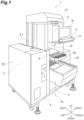
FIG. 1 is an external appearance perspective view illustrating a packaging apparatus according to an embodiment; -
FIG. 2 is a schematic front view illustrating the inside of a stretch packaging apparatus inFIG. 1 ; -
FIG. 3 is a schematic fragmentary view taken along the line III-III inFIG. 2 ; -
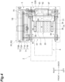
FIG. 4 is a plan schematic view of a stretch packaging apparatus; -
FIG. 5 is a block diagram illustrating a configuration of the stretch packaging apparatus inFIG. 1 ; -
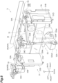
FIG. 6 is a perspective view of a stretching mechanism viewed from diagonally forward right; -
FIG. 7 is a perspective view of the stretching mechanism viewed from diagonally behind left; -
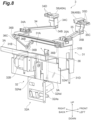
FIG. 8 is a perspective view of the stretching mechanism viewed from diagonally behind left; -
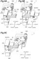
FIG. 9A is an enlarged perspective view of a first clamp at the outer position and original position;FIG. 9B is an enlarged perspective view of a first clamp at the outer position and stretched position;FIG. 9C is an enlarged perspective view of a first clamp at the inner position and original position; -
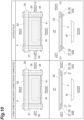
FIG. 10 is a diagram illustrating the operation of packaging an object; -
FIG. 11 is a diagram illustrating the operation of packaging an object; -
FIG. 12 is a diagram illustrating the operation of packaging an object; and -
FIG. 13A to FIG. 13F are diagrams illustrating the operation of the first clamp when the film is pre-stretched. - Hereinafter, a
stretch packaging apparatus 1 according to an embodiment will be described with reference to the accompanying drawings. In the description of the drawings, the same reference numerals denote the same components, and repeated descriptions will be omitted. - As illustrated in
FIG. 1 to FIG. 4 , thestretch packaging apparatus 1 is an apparatus configured to perform film packaging of an object (product) W including a product G such as groceries and a tray T on which the product G is placed. Thestretch packaging apparatus 1 packages the object W with a film F, by pushing up the object W against the film F the peripheral edge part of which is retained in tension from below, and by folding the peripheral part of the film F into the bottom surface side of the tray T. - The
stretch packaging apparatus 1 includes a weighing/carry-inmechanism 2, aroll retaining mechanism 4, afilm feeding mechanism 5, a film conveyance mechanism (film conveyance unit) 6, acutter mechanism 7, a lift mechanism (lift unit) 20, afolding mechanism 25, asealing mechanism 8, a label issuing machine LI, and a control device (control unit) 9. Each mechanism included in thestretch packaging apparatus 1 is housed in amain body 1A and acasing 1B of thestretch packaging apparatus 1. Thecasing 1B is attached to the side of themain body 1A. - In the description of the present embodiment, "left and right" means left and right when the
main body 1A of thestretch packaging apparatus 1 is viewed from the front. The front side of thestretch packaging apparatus 1 in the front-back direction may also be referred to as the "near side", and the opposite side may be referred to as the "far side". Films F 1 and F2 mean either one of the film F 1 and the film F2. The films F1 and F2 may also be simply referred to as a film F. Film rolls R1 and R2 mean either one of the film roll R1 and the film roll R2. The "upstream" and "downstream" each mean the conveyance direction upstream and the conveyance direction downstream of the film F. - As illustrated in
FIG. 3 , the weighing/carry-inmechanism 2 includes aweighing instrument 2A, a carry-inbelt 2B, and a weighing pan 12. Theweighing instrument 2A weighs the object W placed on the weighing pan 12, and outputs information indicating the weight of the object W to a control device 9 (seeFIG. 1 ). The carry-inbelt 2B is stretched over a pair of rollers. The carry-inbelt 2B is provided with aconveyance bar 13 configured to push the object W. Theconveyance bar 13 moves to the far side with the running of the carry-inbelt 2B, and pushes the object W to thelift mechanism 20 on the far side. The weighing pan 12 is a rectangular shallow dish-shaped tray on which the object W is to be placed. - As illustrated in
FIG. 2 , theroll retaining mechanism 4 is installed in thecasing 1B. Theroll retaining mechanism 4 is configured to retain two film rolls R1 and R2 of the same type or different types. Each of the film rolls R1 and R2 is a film roll around which the film F1 or F2 of a certain width is wound in multiple layers. Theroll retaining mechanism 4 includes an upperroll retaining unit 41 configured to retain the film roll R1, a lowerroll retaining unit 42 configured to retain the film roll R2, and aroll drive unit 43 configured to selectively rotate either of the upperroll retaining unit 41 and the lowerroll retaining unit 42, and to cause one of the film rolls R1 and R2 to draw out the film F1 or the film F2. - The
film feeding mechanism 5 is a mechanism configured to deliver the film F1 drawn out from the film roll R1 or the film F2 drawn out from the film roll R2 to a pair of afirst feeder unit 61 and asecond feeder unit 62 of thefilm conveyance mechanism 6. Thefilm feeding mechanism 5 is installed in thecasing 1B. Thefilm feeding mechanism 5 includes aloading unit 70. Theloading unit 70 includes a firstgripping unit 71, a secondgripping unit 72, a rotatingshaft 73, and adrive unit 74. The firstgripping unit 71 and the secondgripping unit 72 are attached to therotating shaft 73. The firstgripping unit 71 and the secondgripping unit 72 extend in a V-shape from the rotatingshaft 73 when viewed from the front-back direction. - As illustrated in
FIG. 2 andFIG. 4 , the firstgripping unit 71 grips the film F1 by twoplate members gripping unit 72 grips the film F2 by twoplate members gripping unit 71 and the secondgripping unit 72 have a predetermined length in the depth direction of thecasing 1B so that the films F1 and F2 can be fed out to thefilm conveyance mechanism 6. Thedrive unit 74 rotates therotating shaft 73, to rotate the firstgripping unit 71 and the secondgripping unit 72. - As illustrated in
FIG. 2 , when the firstgripping unit 71 sends out (feeds out) the film F1 to thefilm conveyance mechanism 6, the rotatingshaft 73 is rotated until the firstgripping unit 71 becomes parallel to the horizontal plane. Consequently, the film F1 is fed out from the tip end of the firstgripping unit 71 to thefilm conveyance mechanism 6 in the horizontal direction. When the secondgripping unit 72 sends out the film F2 to thefilm conveyance mechanism 6, the rotatingshaft 73 is rotated until the secondgripping unit 72 becomes parallel to the horizontal plane. Consequently, the film F2 is fed out from the tip end of the secondgripping unit 72 to thefilm conveyance mechanism 6 in the horizontal direction. - The
film conveyance mechanism 6 receives the film F from thefilm feeding mechanism 5, holds both sides of the film F in the width direction (front-back direction) from the vertical direction, and conveys the film F to a packaging area A above thelift mechanism 20. Moreover, thefilm conveyance mechanism 6 retains the film F received from thefilm feeding mechanism 5 in tension at the center portion of the packaging area A. Thefilm conveyance mechanism 6 includes the first feeder unit 61 (holding unit), the second feeder unit (holding unit) 62, a firstconveyance drive unit 63 illustrated inFIG. 4 , afirst slide mechanism 64, asecond slide mechanism 65, asecond drive unit 66, and athird drive unit 67. - As illustrated in
FIG. 2 andFIG. 3 , thefirst feeder unit 61 includes afirst feeder section 61A and a pair of holdingsections first feeder section 61A conveys the film F fed out from thefilm feeding mechanism 5. The pair of holdingsections first feeder section 61A from the vertical direction. The pair of holdingsections sections first feeder unit 61 may include a plurality of members (three members inFIG. 10 to FIG. 13 ) in the conveyance direction. - The
second feeder unit 62 includes asecond feeder section 62A and a pair of holdingsections second feeder section 62A conveys the film F fed out from thefilm feeding mechanism 5. The pair of holdingsections second feeder section 62A from the vertical direction. The pair of holdingsections second feeder unit 62 may include a plurality of members (three members inFIG. 10 to FIG. 13 ) in the conveyance direction. - The
first feeder unit 61 illustrated inFIG. 2 is disposed on the near side in the front-back direction. Thesecond feeder unit 62 is disposed on the far side in the front-back direction than thefirst feeder unit 61. Thefirst feeder unit 61 and thesecond feeder unit 62 are disposed in the conveyance direction (longitudinal direction) of the film F. Thefirst feeder unit 61 and thesecond feeder unit 62 are driven by the firstconveyance drive unit 63 illustrated inFIG. 4 , and conveys the film F from the left side to the right side. - The
first slide mechanism 64 and thesecond slide mechanism 65 configured to move thefirst feeder unit 61 and thesecond feeder unit 62 in the width direction of the film F are provided on both end parts in the longitudinal direction of thefirst feeder unit 61 and thesecond feeder unit 62 illustrated inFIG. 2 . Thefirst slide mechanism 64 is driven by thesecond drive unit 66 illustrated inFIG. 3 , and moves thefirst feeder unit 61 in the width direction of the film F. Thesecond slide mechanism 65 is driven by thethird drive unit 67, and moves thesecond feeder unit 62 in the width direction of the film F. - After the
film feeding mechanism 5 sends out the film F to thefilm conveyance mechanism 6, thecutter mechanism 7 illustrated inFIG. 2 cuts the film F stretched between thefilm feeding mechanism 5 and thefilm conveyance mechanism 6. Thecutter mechanism 7 cuts the film F stretched between thefilm feeding mechanism 5 and thefilm conveyance mechanism 6, after thefilm conveyance mechanism 6 has conveyed a predetermined amount of the film F. - In the present embodiment, the film F cut by the
cutter mechanism 7 is pre-stretched in the conveyance direction and width direction of the film F. While the film F is held by thefirst feeder unit 61 and thesecond feeder unit 62, the film F is pre-stretched in the width direction, by driving thethird drive unit 67, and moving thesecond feeder unit 62 in the rear direction. How the film F is pre-stretched in the conveyance direction will be described in detail in the section below. - The
lift mechanism 20 is provided in the lower part of themain body 1A. Thelift mechanism 20 receives the bottom surface of the tray T with a plurality ofsupport members 23, and moves asupport base 21 fixed to thesupport members 23 upward by an electricball screw mechanism 24. Consequently, thelift mechanism 20 moves the object W upward by retaining the bottom surface of the tray T. Thelift mechanism 20 pushes up the film F by moving the film F in the vertical direction, while the object W is pressed against the film F retained in tension by thefilm conveyance mechanism 6. - As illustrated in
FIG. 2 andFIG. 3 , thefolding mechanism 25 is provided in the upper part of themain body 1A. The object W is covered by the film F, by folding the peripheral portion of the film F into the bottom surface side of the object W (that is, the bottom surface side of the tray T) pushed up by thelift mechanism 20. Thefolding mechanism 25 includes afirst folding plate 26 and asecond folding plate 27 that are movably provided in the horizontal direction along the conveyance direction of the film F. Thefirst folding plate 26 and thesecond folding plate 27 fold the film F into the bottom surface side of the tray T from both end parts of the object W in the conveyance direction. Thefolding mechanism 25 includes athird folding plate 28 configured to fold the side of the film F on the far side in the width direction, into the bottom surface side of the tray T. Thefolding mechanism 25 includes afront folding bar 29 configured to fold the side of the film F on the near side in the width direction into the bottom surface side of the tray T, when the tray T is discharged to thesealing mechanism 8 side by adischarge pusher 29A. Thefirst folding plate 26, thesecond folding plate 27, and thethird folding plate 28 have a single drive unit, which is not illustrated, and are configured to be driven in conjunction with each other by a plurality of pulleys, a timing belt, and the like. Thefirst folding plate 26, thesecond folding plate 27, and thethird folding plate 28 may also be provided with an independent drive unit, to allow thefirst folding plate 26, thesecond folding plate 27, and thethird folding plate 28 to move to the starting position according to the size of the object W. - A
stretching mechanism 3 illustrated inFIG. 6 is a mechanism configured to retain the film F in a pulled (pre-stretched) state in the conveyance direction (left-right direction), before thelift mechanism 20 causes the object W to push up the film F. Thestretching mechanism 3 is disposed in the rear part of themain body 1A. As illustrated inFIG. 6 to FIG. 8 , thestretching mechanism 3 includes asupport unit 31, a vertical movingmechanism 32, afirst arm 34, asecond arm 35, a movingmechanism 36, afirst clamp 40A, and asecond clamp 40B (a pair of clamps). - The
first clamp 40A and thesecond clamp 40B grip each of both end parts of the film in the conveyance direction of the film F located below thefirst folding plate 26 and the second folding plate 27 (a pair of folding plates) (seeFIG. 2 andFIG. 3 ). Thefirst clamp 40A includes a first pushingplate 38 and thefirst folding plate 26, and holds one end part of the film F in the conveyance direction. Thesecond clamp 40B includes a second pushingplate 39 and thesecond folding plate 27, and holds the other end part of the film F in the conveyance direction. - The
support unit 31 is a member configured to support thefirst arm 34 and thesecond arm 35. Thesupport unit 31 has amain surface part 31A and a pair ofside surface parts slide mechanism 31D such as a linear guide and a cylinder is provided on the pair ofside surface parts support unit 31. Thesupport unit 31 is movably fixed to themain body 1A (seeFIG. 1 ) in the up-and-down direction, by theslide mechanism 31D. The vertical movingmechanism 32 is a mechanism configured to move thesupport unit 31 in the up-and-down direction with respect to themain body 1A. - The vertical moving
mechanism 32 includes alink mechanism 32A and a mainbody drive unit 32B. Thelink mechanism 32A includes a support shaft 32As supported by themain body 1A, an oscillating arm 32Ad configured to move up and down around the support shaft 32As, a crank mechanism 32Ae connected to the oscillating arm 32Ad and the rotary shaft of the mainbody drive unit 32B, and a connecting rod 32Af configured to connect one end of the oscillating arm 32Ad to thesupport unit 31. By rotating the rotary shaft of the mainbody drive unit 32B and operating the crank mechanism 32Ae, thelink mechanism 32A moves thesupport unit 31 in the up-and-down direction. The mainbody drive unit 32B is attached to themain body 1A via abracket 3A and the like. The mainbody drive unit 32B is controlled by the control device 9 (seeFIG. 1 ). - The
first arm 34 includes a parallel link, and is supported by the right end part of thesupport unit 31. Abase end part 34A on thesupport unit 31 side of thefirst arm 34 is rotatably connected to thesupport unit 31. The first pushingplate 38 is provided on thetip end part 34B of thefirst arm 34 on the opposite side from thebase end part 34A via anattachment member 34C. As illustrated inFIG. 9A , aguide member 34D configured to slidably move the first pushingplate 38 is provided on the upper part of theattachment member 34C. Theguide member 34D is a member extending in one direction. As illustrated inFIG. 9A and FIG. 9C , even when thefirst arm 34 is rotated in the horizontal direction, theattachment member 34C connected to thetip end part 34B of thefirst arm 34 is rotatably provided such that the parallel link of thefirst arm 34 maintains the state of theguide member 34D extending in the left-right direction. - Returning to
FIG. 6 to FIG. 8 , similar to thefirst arm 34, thesecond arm 35 includes a parallel link, and is supported by the left end part of thesupport unit 31. Abase end part 35A on thesupport unit 31 side of thesecond arm 35 is rotatably connected to thesupport unit 31. The second pushingplate 39 is provided on thetip end part 35B of thesecond arm 35 on the opposite side from thebase end part 35A via anattachment member 35C. Similar to thefirst arm 34, aguide member 35D configured to slidably move the second pushingplate 39 is provided on the upper part of theattachment member 35C. Theguide member 35D is a member extending in one direction. Even when thesecond arm 35 is rotated in the horizontal direction, theattachment member 35C connected to thetip end part 35B of thesecond arm 35 is rotatably provided such that the parallel link of thesecond arm 35 maintains the state of theguide member 35D extending in the left-right direction. - The
first arm 34 and thesecond arm 35 include the moving mechanism 36 (will be described in detail in the section below) configured to move the first pushingplate 38 and the second pushingplate 39, by causing the first pushingplate 38 and the second pushingplate 39 to follow thefirst folding plate 26 and thesecond folding plate 27 that move to the starting position according to the size of the object W. The second pushingplate 39 provided on thesecond arm 35 via theattachment member 35C is in a state in which the first pushingplate 38 provided on thefirst arm 34 via theattachment member 34C as illustrated inFIG. 9A is laterally inverted. For this reason, illustration of the second pushingplate 39 provided on thesecond arm 35 via theattachment member 35C corresponding toFIG. 9A to FIG. 9C will be omitted. - By rotating the
base end parts first arm 34 and thesecond arm 35 as the base shafts, the movingmechanism 36 illustrated inFIG. 7 andFIG. 8 causes the first pushingplate 38 attached to thetip end part 34B of thefirst arm 34 via theattachment member 34C and the second pushingplate 39 attached to thetip end part 35B of thesecond arm 35 via theattachment member 35C, to approach and separate from each other in the left-right direction. The movingmechanism 36 includes arotation drive unit 36A illustrated inFIG. 6 , a plurality ofpulleys 36B, and atiming belt 36C. - In the moving
mechanism 36, when therotation drive unit 36A is driven, thetiming belt 36C wound around thepulleys 36B runs to rotate thepulleys 36B, and causes thefirst arm 34 and thesecond arm 35 to approach and separate from each other in the horizontal direction in synchronization. Specifically, by rotating thefirst arm 34 and thesecond arm 35, the movingmechanism 36 moves the first pushingplate 38 at thetip end part 34B of thefirst arm 34 to the position below thefirst folding plate 26 that has moved to the starting position, and moves the second pushingplate 39 at thetip end part 35B of thesecond arm 35 to the position below thesecond folding plate 27 that has moved to the starting position. - The first pushing
plate 38 that has moved below thefirst folding plate 26, is movably provided in the same direction as the moving direction (left-right direction) of thefirst folding plate 26, while the film F is sandwiched between thefirst folding plate 26 and the first pushingplate 38. Specifically, the first pushingplate 38 pulls the film F to the right side, and strains (pre-stretches) the film F to the right side, by moving to the right side while the film F is sandwiched (gripped) between thefirst folding plate 26 and the first pushingplate 38. Moreover, the second pushingplate 39 that has moved below thesecond folding plate 27, pre-stretches the film F to the left side, by moving to the left side while the film F is sandwiched (gripped) between thesecond folding plate 27 and the second pushingplate 39. - As illustrate in
FIG. 9A and FIG. 9B , the first pushingplate 38 is movably provided along theguide member 34D. When the first pushingplate 38 moves to the direction away from the second pushing plate 39 (right side), the first pushingplate 38 has anelastic member 38A illustrated inFIG. 13A configured to energize the first pushingplate 38 in a direction returning to the original position (left side). - The first pushing
plate 38 is provided with a part to be engaged 38B that is to be hooked to anengagement part 26A (seeFIG. 13A ) of thefirst folding plate 26. The part to be engaged 38B of the first pushingplate 38 that is moved upward by the operation of the vertical movingmechanism 32 is located on the right side of theengagement part 26A of thefirst folding plate 26, while the film F is sandwiched between thefirst folding plate 26 and the part to be engaged 38B. When thefirst folding plate 26 moves to the right side in this state, the part to be engaged 38B of the first pushingplate 38 is hooked to theengagement part 26A, and causes the first pushingplate 38 to move to the right side. Moreover, when the first pushingplate 38 moves downward by the operation of the vertical movingmechanism 32, the part to be engaged 38B of thefirst folding plate 26 moves away from theengagement part 26A of thefirst folding plate 26. Hence, the first pushingplate 38 returns to the left end of theguide member 34D by the energizing force of theelastic member 38A. - The second pushing
plate 39 moves upward with the first pushingplate 38 by the operation of the vertical movingmechanism 32. Then, because the second pushingplate 39 has a configuration symmetrical to the first pushingplate 38, when thesecond folding plate 27 moves to the left side while the film is sandwiched between thesecond folding plate 27 and the second pushingplate 39, the second pushingplate 39 moves to the left side as thesecond folding plate 27 moves to the left side. Moreover, when the second pushingplate 39 moves downward with the first pushingplate 38, the engagement part of the second pushingplate 39 moves away from thesecond folding plate 27, and returns to the left end of theguide member 34D by the energizing force of an elastic member (not illustrated). - The
sealing mechanism 8 heat-seals the film F folded into the bottom surface of the object W by thefolding mechanism 25. Thesealing mechanism 8 includes a conveyance roller and a heating roller. Thesealing mechanism 8 heat-seals the object W pushed out by thedischarge pusher 29A, while conveying the object W by the conveyance roller and the heating roller. Thesealing mechanism 8 discharges the packaged object W toward a discharge table 82. - The label issuing machine LI includes an attaching machine configured to attach a label printed by a label printer LP onto the discharged and packaged product. The label printer LP prints information relating to the article onto the label. For example, the information relating to the article includes a product name, price, and the like.
- The
control device 9 is a computer disposed in the upper part of themain body 1A. As illustrated inFIG. 5 , thecontrol device 9 controls the operation of each of the mechanisms described above. Thecontrol device 9 includes an input/output interface I/O configured to input and output signals to and from the outside or the like; a Read Only Memory (ROM) in which a computer program, information, or the like for performing processing is stored; a Random Access Memory (RAM) configured to temporarily store data; a storage medium such as a Hard Disk Drive (HDD); a Central Processing Unit (CPU); a communication circuit; and the like. Thecontrol device 9 implements each function, by storing input data in the RAM on the basis of a signal output by the CPU, loading the computer program stored in the ROM to the RAM, and executing the computer program loaded in the RAM. - A
display panel 16 and anoperation unit 17 are connected to thecontrol device 9. For example, thedisplay panel 16 is a touch panel-type display, and operation buttons are also displayed on the display. In theoperation unit 17, various operations and inputs are performed by the user. Thecontrol device 9 refers to various types of data in astorage unit 9A, and calculates the price of the object W or the like, on the basis of the weight of the object W weighed by the weighing/carry-inmechanism 2 and/or the tray size. Thecontrol device 9 controls the operation of the label printer LP and the label issuing machine LI, and prints the weight, price, or the like of the object W on the label. - Before the film F is pushed up by the object W, the
control device 9 in the present embodiment moves thesecond feeder unit 62 of the pair of feeder units (first feeder unit 61 and second feeder unit 62) in a direction away from the first feeder unit 61 (depth direction). Consequently, the film F disposed above the packaging area A is pre-stretched in the width direction. Moreover, before the film F is pushed up by the object W, thecontrol device 9 of the present embodiment moves thefirst folding plate 26 and thesecond folding plate 27, as well as the first pushingplate 38 and the second pushingplate 39, to a position (starting position) according to the size of the object W. Subsequently, while the film F is pressed against thefirst folding plate 26 and thesecond folding plate 27 by the first pushingplate 38 and the second pushingplate 39, by moving the first pushingplate 38 and the second pushingplate 39 upward, thecontrol device 9 moves both of thefirst folding plate 26 and thesecond folding plate 27 in a direction in which a relative distance between thefirst folding plate 26 and thesecond folding plate 27 is increased. Consequently, the film F disposed above the packaging area A is pre-stretched in the conveyance direction. Thecontrol device 9 pushes up the object W against the film F that is pre-stretched in both directions in the width direction and conveyance direction in this manner. That is, thecontrol device 9 moves the object W upward by controlling thelift mechanism 20. - In this embodiment, the film F is pre-stretched in the conveyance direction, by causing the
first folding plate 26 and thesecond folding plate 27 on the left and right to separate from each other in the conveyance direction of the film F, while the end part of the film F is sandwiched between thefirst folding plate 26 and the first pushingplate 38, and between thesecond folding plate 27 and the second pushingplate 39. However, instead of this configuration, the film F may also be pre-stretched in the conveyance direction, by providing thefirst clamp 40A and thesecond clamp 40B configured to grip the end part of the film F from above and below, and causing thefirst clamp 40A and thesecond clamp 40B to separate from each other in the left-right direction by the movingmechanism 36 described above. - Next, in the
stretch packaging apparatus 1 configured in this manner, an operation of packaging the object W by pre-stretching the film F in both directions in the width direction and conveyance direction will be described, mainly with reference toFIG. 10 to FIG. 12 . - To package the object W with the film F, the film F is conveyed to the upper part of the packaging area A by the
film conveyance mechanism 6, and as illustrated in (1) inFIG. 10 , the upper part of the object W is covered by the film F, when thecutter mechanism 7 cuts the upstream side of the film F in the conveyance direction. In such a state, thesecond feeder unit 62 configured to hold the film F on one side of the film F in the width direction, moves to the rear side. Consequently, the pre-stretching of the film F in the width direction is completed. - Next, as illustrated in
FIG. 13A , the first pushingplate 38 and the second pushingplate 39 move upward, and as illustrated in (2) inFIG. 10 andFIG. 13B , push the film F against the lower surface of thefirst folding plate 26 and thesecond folding plate 27. Consequently, the right end of the film F in the conveyance direction is held by thefirst folding plate 26 and the first pushingplate 38, and the left end of the film F in the conveyance direction is held by thesecond folding plate 27 and the second pushingplate 39. - In the state illustrated in (2) in
FIG. 10 , thefirst folding plate 26 is moved to the right side, and thesecond folding plate 27 is moved to the left side. Consequently, as illustrated inFIG. 13C , the first pushingplate 38 having the part to be engaged 38B that is hooked to theengagement part 26A of thefirst folding plate 26, moves to the right side as thefirst folding plate 26 moves. Moreover, the second pushingplate 39 having a part to be engaged 39B that is hooked to an engagement part 27A of thesecond folding plate 27 also moves to the left side as thesecond folding plate 27 moves. Consequently, as illustrated in (3) inFIG. 11 , both ends of the film F in the conveyance direction are pulled, and the pre-stretching of the film F in the conveyance direction is completed. - Next, the film F is pushed upward, by pressing the object W against the film F on which the pre-stretching is completed in the width direction and conveyance direction of the film F. As illustrated in (4) in
FIG. 11 ,FIG. 13D, and FIG. 13E , for some time after the film F is pushed up by the object W, the first pushingplate 38 and the second pushingplate 39 keep the film F pushed against the lower surface of thefirst folding plate 26 and the lower surface of thesecond folding plate 27. That is, the position of the peripheral edge part of the film F is remained fixed. - Next, at an appropriate timing after the object W has reached the uppermost position, the peripheral edge part of the film F held by the
first feeder unit 61, the first pushingplate 38, and the second pushingplate 39 is released. Specifically, in thefirst feeder unit 61, the film F is released when the gap between the pair of holdingsections FIG. 13F , the film F is released when thesupport unit 31 moves downward, and the gap between the first pushingplate 38 and thefirst folding plate 26 and the gap between the second pushingplate 39 and thesecond folding plate 27 are increased. At this point, the first pushingplate 38 and the second pushingplate 39 return to the starting position illustrated in (1) inFIG. 10 , by the action of eachelastic member 38A. - Next, as illustrated in (5) in
FIG. 12 , thefirst folding plate 26 moves to the left side, and thesecond folding plate 27 moves to the right side, to fold the peripheral edge part of the film F in the conveyance direction into the bottom surface side of the object W. Next, as illustrated in (6) inFIG. 12 , thethird folding plate 28 moves to the front side, to fold the peripheral edge part of the film F in the width direction into the bottom surface side of the object W. Lastly, thedischarge pusher 29A moves forward to push out the object W to thesealing mechanism 8. At this point, the film F in front of the object W is folded into the bottom surface side of the object W. Consequently, the packaging of the object W with the film F is completed. - The effects of the
stretch packaging apparatus 1 in the embodiment described above will be explained. In thestretch packaging apparatus 1 of the embodiment described above, the film F having been stretched (having been pre-stretched) in the conveyance direction of the film F is pushed up by the object W. Consequently, the object W is packaged while the film F is stretched in the conveyance direction. Hence, compared to when the object W is packaged while the film F is not stretched in the conveyance direction, it is possible to reduce the length of the film F to be used. That is, with this configuration, it is possible to perform wrinkle-less packaging, while reducing the length of the film F to be used. - In the
stretch packaging apparatus 1 of the embodiment described above, the moving mechanism configured to move the first pushingplate 38 and the second pushingplate 39 is configured such that the first pushingplate 38 and the second pushingplate 39 move as thefirst folding plate 26 and thesecond folding plate 27 move. Consequently, it is possible to pull both end parts of the film F in the conveyance direction, and easily stretch the film F in the conveyance direction. - The
stretch packaging apparatus 1 of the embodiment described above is configured such that, in a state where the first pushingplate 38 and the second pushingplate 39 push one end part of the film F against thefirst folding plate 26 and push the other end part of the film F against thesecond folding plate 27, when thefirst folding plate 26 and thesecond folding plate 27 move, the first pushingplate 38 and the second pushingplate 39 also move by following thefirst folding plate 26 and thesecond folding plate 27. In the embodiment described above, it is possible to use the existing moving structure of thefirst folding plate 26 and thesecond folding plate 27 configured to fold both end parts of the film F in the conveyance direction into the bottom surface side of the object W, by causing thefirst folding plate 26 and thesecond folding plate 27 to approach and separate from each other in the conveyance direction of the film F. Consequently, there is no need to incorporate a separate moving mechanism for causing a pair of clamps retaining the film F to approach and separate from each other in the conveyance direction of the film F. Hence, it is possible to configure the clamps for retaining the film F at a low cost. Moreover, by simply causing the first pushingplate 38 and the second pushingplate 39 on the left and right to press both end parts of the film F in the conveyance direction against thefirst folding plate 26 and thesecond folding plate 27 on the left and right, it is possible to move the pair of first pushingplate 38 and the second pushingplate 39 as the pair offirst folding plate 26 and thesecond folding plate 27 move. Consequently, because there is no need to control and synchronize the movements of the plates, simple structure and control are possible. - In this embodiment, the first pushing
plate 38 and the second pushingplate 39 are moved vertically by the vertical movingmechanism 32. However, a first plate and a second plate that move vertically by a solenoid may be disposed on the upper part of each of the first pushingplate 38 and the second pushingplate 39, and the end part of the film F may be gripped between the first plate and the first pushingplate 38, and between the second plate and the second pushingplate 39. - In the
stretch packaging apparatus 1 of the embodiment described above, thecontrol device 9 moves thesecond feeder unit 62 in a direction in which a relative distance from thefirst feeder unit 61 is increased, before the film F is pushed up by the object W. Consequently, because the film F having been pre-stretched in both directions in the conveyance direction of the film F and the width direction of the film F is pushed up by the object W, further wrinkle-less packaging becomes possible. - While an embodiment has been described above, an aspect of the present invention is not limited to the embodiment described above. Various changes may be made without departing from the scope of the invention.
- In the embodiment described above, the
stretch packaging apparatus 1 including the weighing function and the pricing function by attaching a label, in addition to the film packaging function has been described as an example. However, thestretch packaging apparatus 1 may not include at least one of the weighing function and the pricing function. - In the embodiment and modification described above, an example in which the relative distance between the first pushing
plate 38 and the second pushingplate 39 becomes approachable or separable by the movingmechanism 36 has been described. However, the relative distance therebetween may become approachable or separable, when only one of the first pushingplate 38 and the second pushingplate 39 moves. - In the embodiment and modification described above, an example in which the relative distance between the
first feeder unit 61 and thesecond feeder unit 62 becomes approachable or separable, when only thesecond feeder unit 62 moves has been described. However, the relative distance therebetween may become approachable or separable, when both of thefirst feeder unit 61 and thesecond feeder unit 62 move. - In the embodiment and modification described above, the first pushing
plate 38 and the second pushingplate 39 move by following the movement of thefirst folding plate 26 and thesecond folding plate 27. However, it is not limited thereto. For example, the movingmechanism 36 configured to cause the first pushingplate 38 and the second pushingplate 39 to approach and separate from each other may be used to drive and control the first pushingplate 38 and the second pushingplate 39 to separate in the left-right direction such that the film F is pre-stretched in the conveyance direction. In this case, thecontrol device 9 may control such that thefirst folding plate 26 and the first pushingplate 38 move in synchronization, and thesecond folding plate 27 and the second pushingplate 39 also move in synchronization.
Claims (3)
- A stretch packaging apparatus, comprising:a film conveyance unit configured to convey a film to a packaging area by holding both sides of the film in a width direction intersecting with a conveyance direction of the film;a lift unit configured to push up the film conveyed to the packaging area by moving the film upward, the film being pushed up while a product is pressed against the film from below;a pair of folding plates configured to fold a peripheral edge part of the film pushed up by the lift unit, the peripheral edge part of the film being folded into a bottom surface side of the product;a pair of clamps configured to grip each of both end parts of the film in the conveyance direction of the film located below the pair of folding plates;a moving mechanism configured to move the pair of clamps; anda control unit configured to control movement of the moving mechanism, whereinthe control unit controls the moving mechanism to pre-stretch the film in the conveyance direction of the film by moving at least one of the pair of clamps in a direction in which a relative distance between the pair of clamps is increased.
- The stretch packaging apparatus according to claim 1, whereinthe pair of clamps has the pair of folding plates and a pair of pushing plates configured to push the film against each of the pair of folding plates from below,the moving mechanism is configured to move the pushing plates as the folding plates moves, andthe control unit moves at least one of the folding plates in a direction in which a relative distance between the folding plates is increased, while each of both end parts of the film in the conveyance direction is pushed against each of the folding plates by the pair of pushing plates.
- The stretch packaging apparatus according to claim 1 or 2, whereinthe film conveyance unit includes a pair of holding units disposed so as to face the width direction, andthe control unit moves at least one of the pair of holding units in a direction in which a relative distance between the holding units is increased before the film is pushed up by the product.
Applications Claiming Priority (1)
| Application Number | Priority Date | Filing Date | Title |
|---|---|---|---|
| JP2023093763A JP2024175772A (en) | 2023-06-07 | 2023-06-07 | Stretch wrapping equipment |
Publications (2)
| Publication Number | Publication Date |
|---|---|
| EP4477567A1 true EP4477567A1 (en) | 2024-12-18 |
| EP4477567B1 EP4477567B1 (en) | 2026-03-18 |
Family
ID=91431451
Family Applications (1)
| Application Number | Title | Priority Date | Filing Date |
|---|---|---|---|
| EP24180242.0A Active EP4477567B1 (en) | 2023-06-07 | 2024-06-05 | Stretch packaging apparatus |
Country Status (3)
| Country | Link |
|---|---|
| EP (1) | EP4477567B1 (en) |
| JP (1) | JP2024175772A (en) |
| CN (1) | CN119099964A (en) |
Citations (5)
| Publication number | Priority date | Publication date | Assignee | Title |
|---|---|---|---|---|
| EP0308085A1 (en) * | 1987-09-15 | 1989-03-22 | Premark Feg Corporation | Package wrapping method and machine |
| JPH06156412A (en) * | 1992-11-30 | 1994-06-03 | Teraoka Seiko Co Ltd | Stretch packaging device |
| EP1036738A1 (en) * | 1998-07-08 | 2000-09-20 | ULMA C y E, S. COOP. | Machine for wrapping products with an extensible film |
| JP2014181061A (en) * | 2013-03-19 | 2014-09-29 | Ishida Co Ltd | Packaging machine |
| JP2017057004A (en) | 2015-09-18 | 2017-03-23 | 株式会社イシダ | Packaging equipment |
-
2023
- 2023-06-07 JP JP2023093763A patent/JP2024175772A/en active Pending
-
2024
- 2024-05-28 CN CN202410673277.4A patent/CN119099964A/en active Pending
- 2024-06-05 EP EP24180242.0A patent/EP4477567B1/en active Active
Patent Citations (5)
| Publication number | Priority date | Publication date | Assignee | Title |
|---|---|---|---|---|
| EP0308085A1 (en) * | 1987-09-15 | 1989-03-22 | Premark Feg Corporation | Package wrapping method and machine |
| JPH06156412A (en) * | 1992-11-30 | 1994-06-03 | Teraoka Seiko Co Ltd | Stretch packaging device |
| EP1036738A1 (en) * | 1998-07-08 | 2000-09-20 | ULMA C y E, S. COOP. | Machine for wrapping products with an extensible film |
| JP2014181061A (en) * | 2013-03-19 | 2014-09-29 | Ishida Co Ltd | Packaging machine |
| JP2017057004A (en) | 2015-09-18 | 2017-03-23 | 株式会社イシダ | Packaging equipment |
Also Published As
| Publication number | Publication date |
|---|---|
| EP4477567B1 (en) | 2026-03-18 |
| JP2024175772A (en) | 2024-12-19 |
| CN119099964A (en) | 2024-12-10 |
Similar Documents
| Publication | Publication Date | Title |
|---|---|---|
| JP3193728U (en) | Stretch wrapping machine | |
| JP6235497B2 (en) | Packaging equipment | |
| JP6059747B2 (en) | Stretch wrapping machine | |
| JP6571938B2 (en) | Packaging equipment | |
| US11046467B2 (en) | Packaging apparatus | |
| EP0368496A1 (en) | Wrapping apparatus | |
| EP4477567B1 (en) | Stretch packaging apparatus | |
| US10710755B2 (en) | Packaging apparatus | |
| JP7207681B2 (en) | packaging equipment | |
| JP3569939B2 (en) | Stretch wrapping machine | |
| JP4764577B2 (en) | Packaging equipment | |
| JP5666943B2 (en) | Stretch packaging equipment | |
| JP3708640B2 (en) | Stretch wrapping machine | |
| JP3189989U (en) | Packaging equipment | |
| JP6450404B2 (en) | Packaging equipment | |
| JP3385956B2 (en) | Stretch wrapping machine | |
| JP4193416B2 (en) | Stretch film packaging machine | |
| CN120096881A (en) | Packaging device | |
| JP4011639B2 (en) | Stretch wrapping machine | |
| JP5569005B2 (en) | Packaging equipment | |
| JPH0454890Y2 (en) | ||
| JP2001247103A (en) | Packaging machine | |
| JP2012176777A (en) | Stretch packaging apparatus | |
| JP2007223638A (en) | Packaging equipment | |
| JP2000016404A (en) | Stretch-wrap packaging machine |
Legal Events
| Date | Code | Title | Description |
|---|---|---|---|
| PUAI | Public reference made under article 153(3) epc to a published international application that has entered the european phase |
Free format text: ORIGINAL CODE: 0009012 |
|
| STAA | Information on the status of an ep patent application or granted ep patent |
Free format text: STATUS: REQUEST FOR EXAMINATION WAS MADE |
|
| 17P | Request for examination filed |
Effective date: 20240605 |
|
| AK | Designated contracting states |
Kind code of ref document: A1 Designated state(s): AL AT BE BG CH CY CZ DE DK EE ES FI FR GB GR HR HU IE IS IT LI LT LU LV MC ME MK MT NL NO PL PT RO RS SE SI SK SM TR |
|
| GRAP | Despatch of communication of intention to grant a patent |
Free format text: ORIGINAL CODE: EPIDOSNIGR1 |
|
| STAA | Information on the status of an ep patent application or granted ep patent |
Free format text: STATUS: GRANT OF PATENT IS INTENDED |
|
| INTG | Intention to grant announced |
Effective date: 20251028 |
|
| GRAS | Grant fee paid |
Free format text: ORIGINAL CODE: EPIDOSNIGR3 |
|
| GRAA | (expected) grant |
Free format text: ORIGINAL CODE: 0009210 |
|
| STAA | Information on the status of an ep patent application or granted ep patent |
Free format text: STATUS: THE PATENT HAS BEEN GRANTED |
|
| AK | Designated contracting states |
Kind code of ref document: B1 Designated state(s): AL AT BE BG CH CY CZ DE DK EE ES FI FR GB GR HR HU IE IS IT LI LT LU LV MC ME MK MT NL NO PL PT RO RS SE SI SK SM TR |
|
| REG | Reference to a national code |
Ref country code: CH Ref legal event code: F10 Free format text: ST27 STATUS EVENT CODE: U-0-0-F10-F00 (AS PROVIDED BY THE NATIONAL OFFICE) Effective date: 20260318 Ref country code: GB Ref legal event code: FG4D |
|
| REG | Reference to a national code |
Ref country code: IE Ref legal event code: FG4D |
|
| REG | Reference to a national code |
Ref country code: DE Ref legal event code: R096 Ref document number: 602024003227 Country of ref document: DE |