EP4477487A2 - Electrical architecture for powering transportation refrigeration unit - Google Patents
Electrical architecture for powering transportation refrigeration unit Download PDFInfo
- Publication number
- EP4477487A2 EP4477487A2 EP24193739.0A EP24193739A EP4477487A2 EP 4477487 A2 EP4477487 A2 EP 4477487A2 EP 24193739 A EP24193739 A EP 24193739A EP 4477487 A2 EP4477487 A2 EP 4477487A2
- Authority
- EP
- European Patent Office
- Prior art keywords
- power
- converter
- energy storage
- grid
- bus
- Prior art date
- Legal status (The legal status is an assumption and is not a legal conclusion. Google has not performed a legal analysis and makes no representation as to the accuracy of the status listed.)
- Pending
Links
Images




Classifications
-
- B—PERFORMING OPERATIONS; TRANSPORTING
- B60—VEHICLES IN GENERAL
- B60H—ARRANGEMENTS OF HEATING, COOLING, VENTILATING OR OTHER AIR-TREATING DEVICES SPECIALLY ADAPTED FOR PASSENGER OR GOODS SPACES OF VEHICLES
- B60H1/00—Heating, cooling or ventilating devices
- B60H1/00007—Combined heating, ventilating, or cooling devices
- B60H1/00014—Combined heating, ventilating, or cooling devices for load cargos on load transporting vehicles
-
- B—PERFORMING OPERATIONS; TRANSPORTING
- B60—VEHICLES IN GENERAL
- B60H—ARRANGEMENTS OF HEATING, COOLING, VENTILATING OR OTHER AIR-TREATING DEVICES SPECIALLY ADAPTED FOR PASSENGER OR GOODS SPACES OF VEHICLES
- B60H1/00—Heating, cooling or ventilating devices
- B60H1/00357—Air-conditioning arrangements specially adapted for particular vehicles
- B60H1/00364—Air-conditioning arrangements specially adapted for particular vehicles for caravans or trailers
-
- B—PERFORMING OPERATIONS; TRANSPORTING
- B60—VEHICLES IN GENERAL
- B60H—ARRANGEMENTS OF HEATING, COOLING, VENTILATING OR OTHER AIR-TREATING DEVICES SPECIALLY ADAPTED FOR PASSENGER OR GOODS SPACES OF VEHICLES
- B60H1/00—Heating, cooling or ventilating devices
- B60H1/00421—Driving arrangements for parts of a vehicle air-conditioning
- B60H1/00428—Driving arrangements for parts of a vehicle air-conditioning electric
-
- B—PERFORMING OPERATIONS; TRANSPORTING
- B60—VEHICLES IN GENERAL
- B60H—ARRANGEMENTS OF HEATING, COOLING, VENTILATING OR OTHER AIR-TREATING DEVICES SPECIALLY ADAPTED FOR PASSENGER OR GOODS SPACES OF VEHICLES
- B60H1/00—Heating, cooling or ventilating devices
- B60H1/32—Cooling devices
- B60H1/3204—Cooling devices using compression
- B60H1/3232—Cooling devices using compression particularly adapted for load transporting vehicles
-
- B—PERFORMING OPERATIONS; TRANSPORTING
- B60—VEHICLES IN GENERAL
- B60K—ARRANGEMENT OR MOUNTING OF PROPULSION UNITS OR OF TRANSMISSIONS IN VEHICLES; ARRANGEMENT OR MOUNTING OF PLURAL DIVERSE PRIME-MOVERS IN VEHICLES; AUXILIARY DRIVES FOR VEHICLES; INSTRUMENTATION OR DASHBOARDS FOR VEHICLES; ARRANGEMENTS IN CONNECTION WITH COOLING, AIR INTAKE, GAS EXHAUST OR FUEL SUPPLY OF PROPULSION UNITS IN VEHICLES
- B60K11/00—Arrangement in connection with cooling of propulsion units
- B60K11/06—Arrangement in connection with cooling of propulsion units with air cooling
-
- F—MECHANICAL ENGINEERING; LIGHTING; HEATING; WEAPONS; BLASTING
- F25—REFRIGERATION OR COOLING; COMBINED HEATING AND REFRIGERATION SYSTEMS; HEAT PUMP SYSTEMS; MANUFACTURE OR STORAGE OF ICE; LIQUEFACTION SOLIDIFICATION OF GASES
- F25D—REFRIGERATORS; COLD ROOMS; ICE-BOXES; COOLING OR FREEZING APPARATUS NOT OTHERWISE PROVIDED FOR
- F25D29/00—Arrangement or mounting of control or safety devices
- F25D29/003—Arrangement or mounting of control or safety devices for movable devices
-
- H—ELECTRICITY
- H02—GENERATION; CONVERSION OR DISTRIBUTION OF ELECTRIC POWER
- H02J—ELECTRIC POWER NETWORKS; CIRCUIT ARRANGEMENTS OR SYSTEMS FOR SUPPLYING OR DISTRIBUTING ELECTRIC POWER; SYSTEMS FOR STORING ELECTRIC ENERGY
- H02J1/00—Circuit arrangements for DC mains or DC distribution networks
- H02J1/10—Parallel operation of DC sources
- H02J1/102—Parallel operation of DC sources being switching converters
-
- H—ELECTRICITY
- H02—GENERATION; CONVERSION OR DISTRIBUTION OF ELECTRIC POWER
- H02J—ELECTRIC POWER NETWORKS; CIRCUIT ARRANGEMENTS OR SYSTEMS FOR SUPPLYING OR DISTRIBUTING ELECTRIC POWER; SYSTEMS FOR STORING ELECTRIC ENERGY
- H02J3/00—Circuit arrangements for AC mains or AC distribution networks
- H02J3/28—Arrangements for balancing of the load in networks by storage of energy
- H02J3/32—Arrangements for balancing of the load in networks by storage of energy using batteries or super capacitors with converting means
-
- H—ELECTRICITY
- H02—GENERATION; CONVERSION OR DISTRIBUTION OF ELECTRIC POWER
- H02J—ELECTRIC POWER NETWORKS; CIRCUIT ARRANGEMENTS OR SYSTEMS FOR SUPPLYING OR DISTRIBUTING ELECTRIC POWER; SYSTEMS FOR STORING ELECTRIC ENERGY
- H02J7/00—Circuit arrangements for charging or discharging batteries or for supplying loads from batteries
- H02J7/14—Circuit arrangements for charging or discharging batteries or for supplying loads from batteries for charging batteries from dynamo-electric generators driven at varying speed, e.g. on vehicle
- H02J7/1415—Circuit arrangements for charging or discharging batteries or for supplying loads from batteries for charging batteries from dynamo-electric generators driven at varying speed, e.g. on vehicle with a generator driven by a prime mover other than the motor of a vehicle
-
- B—PERFORMING OPERATIONS; TRANSPORTING
- B60—VEHICLES IN GENERAL
- B60H—ARRANGEMENTS OF HEATING, COOLING, VENTILATING OR OTHER AIR-TREATING DEVICES SPECIALLY ADAPTED FOR PASSENGER OR GOODS SPACES OF VEHICLES
- B60H1/00—Heating, cooling or ventilating devices
- B60H1/32—Cooling devices
- B60H2001/3236—Cooling devices information from a variable is obtained
- B60H2001/3255—Cooling devices information from a variable is obtained related to temperature
- B60H2001/3261—Cooling devices information from a variable is obtained related to temperature of the air at an evaporating unit
-
- B—PERFORMING OPERATIONS; TRANSPORTING
- B60—VEHICLES IN GENERAL
- B60H—ARRANGEMENTS OF HEATING, COOLING, VENTILATING OR OTHER AIR-TREATING DEVICES SPECIALLY ADAPTED FOR PASSENGER OR GOODS SPACES OF VEHICLES
- B60H1/00—Heating, cooling or ventilating devices
- B60H1/32—Cooling devices
- B60H2001/3286—Constructional features
- B60H2001/3292—Compressor drive is electric only
-
- B—PERFORMING OPERATIONS; TRANSPORTING
- B60—VEHICLES IN GENERAL
- B60Y—INDEXING SCHEME RELATING TO ASPECTS CROSS-CUTTING VEHICLE TECHNOLOGY
- B60Y2200/00—Type of vehicle
- B60Y2200/10—Road Vehicles
- B60Y2200/14—Trucks; Load vehicles, Busses
- B60Y2200/147—Trailers, e.g. full trailers or caravans
-
- H—ELECTRICITY
- H02—GENERATION; CONVERSION OR DISTRIBUTION OF ELECTRIC POWER
- H02J—ELECTRIC POWER NETWORKS; CIRCUIT ARRANGEMENTS OR SYSTEMS FOR SUPPLYING OR DISTRIBUTING ELECTRIC POWER; SYSTEMS FOR STORING ELECTRIC ENERGY
- H02J2105/00—Networks for supplying or distributing electric power characterised by their spatial reach or by the load
- H02J2105/30—Networks for supplying or distributing electric power characterised by their spatial reach or by the load the load networks being external to vehicles, i.e. exchanging power with vehicles
- H02J2105/33—Networks for supplying or distributing electric power characterised by their spatial reach or by the load the load networks being external to vehicles, i.e. exchanging power with vehicles exchanging power with road vehicles
-
- Y—GENERAL TAGGING OF NEW TECHNOLOGICAL DEVELOPMENTS; GENERAL TAGGING OF CROSS-SECTIONAL TECHNOLOGIES SPANNING OVER SEVERAL SECTIONS OF THE IPC; TECHNICAL SUBJECTS COVERED BY FORMER USPC CROSS-REFERENCE ART COLLECTIONS [XRACs] AND DIGESTS
- Y02—TECHNOLOGIES OR APPLICATIONS FOR MITIGATION OR ADAPTATION AGAINST CLIMATE CHANGE
- Y02T—CLIMATE CHANGE MITIGATION TECHNOLOGIES RELATED TO TRANSPORTATION
- Y02T10/00—Road transport of goods or passengers
- Y02T10/80—Technologies aiming to reduce greenhouse gasses emissions common to all road transportation technologies
- Y02T10/88—Optimized components or subsystems, e.g. lighting, actively controlled glasses
Definitions
- the subject matter disclosed herein generally relates to transportation refrigeration units, and more specifically to an apparatus and a method for powering transportation refrigeration unit with a generator and an energy storage device.
- further embodiments may include a DC/DC converter operably connected to a variable DC bus, the DC/DC converter configured to convert a variable DC power to a fixed DC power on a fixed DC bus.
- further embodiments may include that the generator power converter is configured to receive a first three phase AC power provided by the AC generator and transmit a generator DC power to one of a fixed DC bus or a variable DC bus.
- further embodiments may include that the generator power converter includes an AC/DC converter and the generator three phase AC power exhibits a first AC voltage and a first AC current, at a first frequency, and generator DC power exhibits a second DC voltage and a second DC current.
- further embodiments may include that the grid power converter is configured to receive a first three phase AC power provided by the grid power source and transmit a grid DC power to one of a fixed DC bus or a variable DC bus.
- further embodiments may include that the grid power converter includes a voltage control function, and a current control function, wherein at least the voltage control function is responsive at least in part to the AC power requirement.
- the energy storage system includes an energy storage device and at least one of an first energy storage system DC/DC converter configured to provide DC power to the power management system based at least in part on the AC power requirement and a second energy storage system DC/DC converter configured to convert at least a portion of the DC power on the fixed DC bus to supply the variable DC bus and the energy storage device.
- further embodiments may include a battery management system operably connected to the TRU controller and configured to monitor at least a state of charge of the energy storage device.
- further embodiments may include that the energy storage system DC/DC converter and the second energy storage system DC/DC converter are integrated and wherein the first energy storage system DC/DC converter is operably connected to the TRU controller and configured to direct power flows to the fixed DC bus and the power management system and from the fixed DC bus to the variable DC bus based on at least one of the AC power requirement and the state of charge of the energy storage device.
- further embodiments may include that the energy storage device comprises at least one of a battery, fuel cell, and flow battery.
- further embodiments may include that the power management system includes a DC/AC converter and the second three phase AC power exhibits a second three phase AC voltage and a second AC current, at a second frequency.
- further embodiments may include that the grid power converter, generator power converter, energy storage device, and power management system are operably connected to the variable DC bus.
- further embodiments may include that the grid power converter, generator power converter, the power management system, and energy storage system DC/DC converter are operably connected to the fixed DC bus, and the energy storage system DC/DC converter and energy storage device are operably connected to the variable DC bus.
- further embodiments may include that the grid power converter and power management system and energy storage system DC/DC converter are connected to the fixed DC bus, and the energy storage system DC/DC converter and generator power converter and energy storage device are operably connected to the variable DC bus.
- further embodiments may include that the grid power converter, the generator power converter, energy storage system DC/DC converter and energy storage device are connected to the variable DC bus, and the energy storage system DC/DC converter and the power management system are operably connected to the fixed DC bus.
- further embodiments may include that the grid power converter, power management system, the energy storage system DC/DC converter, and energy storage device are connected to the variable DC bus, and the energy storage system DC/DC converter and the generator power converter are operably connected to the fixed DC bus.
- further embodiments may include that the grid power converter, the generator power converter, the energy storage system DC/DC converter are connected to the fixed DC bus, and the energy storage system DC/DC converter, the energy storage device, and the power management system are operably connected to the variable DC bus.
- further embodiments may include that the grid power converter, and the energy storage system DC/DC converter are connected to the fixed DC bus, and the energy storage system DC/DC converter, the generator power converter, the energy storage device, and the power management system are operably connected to the variable DC bus.
- further embodiments may include that the generator power converter and power management system and energy storage system DC/DC converter are connected to the fixed DC bus, and the energy storage system DC/DC converter and grid power converter and energy storage device are operably connected to the variable DC bus.
- further embodiments may include a return air temperature (RAT) sensor disposed in the return airflow and configured measure the temperature of the return airflow, the RAT sensor operably connected to the TRU controller, the TRU controller configured to execute a process to determine the AC power requirement for the TRU based at least in part on the RAT.
- RAT return air temperature
- inventions of the present disclosure include a transportation refrigeration unit coupled to and powered by an external generator system via a generator power converter, where the power generated by the generator and converted by the generator power converter is based on an AC power requirement of the transportation refrigeration unit.
- the transport refrigeration systems 20 may include a tractor or vehicle 22, a container 24, and an engineless transportation refrigeration unit (TRU) 26.
- the container 24 may be pulled by a vehicle 22. It is understood that embodiments described herein may be applied to shipping containers that are shipped by rail, sea, air, or any other suitable container, thus the vehicle may be a truck, train, boat, airplane, helicopter, etc.
- the vehicle 22 may include an operator's compartment or cab 28 and a combustion engine 42 which is part of the powertrain or drive system of the vehicle 22.
- the vehicle 22 may be a hybrid or all electric configuration having electric motors to provide propulsive force for the vehicle.
- the TRU system 26 may be engineless.
- a small engine or the engine of the vehicle 22 may be employed to power or partially power the TRU 26.
- the container 24 may be coupled to the vehicle 22 and is thus pulled or propelled to desired destinations.
- the trailer may include a top wall 30, a bottom wall 32 opposed to and spaced from the top wall 30, two side walls 34 spaced from and opposed to one-another, and opposing front and rear walls 36, 38 with the front wall 36 being closest to the vehicle 22.
- the TRU 26 is associated with a container 24 to provide desired environmental parameters, such as, for example temperature, pressure, humidity, carbon dioxide, ethylene, ozone, light exposure, vibration exposure, and other conditions to the cargo compartment 40.
- desired environmental parameters such as, for example temperature, pressure, humidity, carbon dioxide, ethylene, ozone, light exposure, vibration exposure, and other conditions to the cargo compartment 40.
- the TRU 26 is a refrigeration system capable of providing a desired temperature and humidity range.
- Operation of the engineless TRU 26 may best be understood by starting at the compressor 58, where the suction gas (e.g., natural refrigerant, hydrofluorocarbon (HFC) R-404a, HFC R-134a... etc.) enters the compressor 58 at a suction port 84 and is compressed to a higher temperature and pressure.
- the refrigerant gas is emitted from the compressor 58 at an outlet port 85 and may then flow into tube(s) 86 of the condenser 64.
- the air flow across the condenser 64 may be facilitated by one or more fans 88 of the condenser fan assembly 66.
- the condenser fans 88 may be driven by respective condenser fan motors 90 of the fan assembly 66 that may be electric.
- the refrigerant gas within the tubes 86 condenses to a high pressure and high temperature liquid and flows to the receiver 68 that provides storage for excess liquid refrigerant during low temperature operation.
- the liquid refrigerant may pass through a sub-cooler heat exchanger 92 of the condenser 64, through the filter-dryer 70 that keeps the refrigerant clean and dry, then to the heat exchanger 72 that increases the refrigerant sub-cooling, and finally to the expansion valve 74.
- FIG. 2 also illustrates airflow through the TRU 26 and the cargo compartment 40.
- Airflow is circulated into and through and out of the cargo compartment 40 of the container 24 by means of the TRU 26.
- a return airflow 134 flows into the TRU 26 from the cargo compartment 40 through a return air intake 136, and across the evaporator 76 via the fan 96, thus conditioning the return airflow 134 to a selected or predetermined temperature.
- the conditioned return airflow 134 now referred to as supply airflow 138, is supplied into the cargo compartment 40 of the container 24 through the refrigeration unit outlet 140, which in some embodiments is located near the top wall 30 of the container 24.
- the supply airflow 138 cools the perishable goods in the cargo compartment 40 of the container 24.
- the TRU 26 can further be operated in reverse to warm the container 24 when, for example, the outside temperature is very low.
- the power management system 190 includes a DC/AC converter 194.
- the DC/AC converter 194 is configured to receive DC power on the DC bus 125 denoted in this instance 125a (e.g., second DC voltage V 2 , a second DC current I 2 from the generator power converter 165; and/or V G , I G 185; and/or DC voltage 155 from the energy storage device 152; alone or as combined) and generate three phase AC power 195 (e.g., at AC voltage V 2 , AC current I 2 a frequency f 2 ), for providing power to the TRU system 26.
- the DC/AC converter 194 includes a voltage control function, a current control function, and a frequency control function, each configured to facilitate the conversion.
- the TRU controller 82 provides command signals denoted by line 191, to the power management system 190.
- the commands are based, at least, on the power consumption requirements of the TRU 26 as discussed further herein.
- the TRU controller 82 may receive status information also depicted by line 191 regarding the DC/AC converter 194.
- the communications may be over standard communication interfaces such as CAN, RS-485, and the like.
- the communications may be wired or wireless.
- the TRU controller 82 identifies the power requirements for the TRU 26 at least partially based on the RAT.
- the TRU controller 82 conveys the power requirements to the power management system 190 and/or the generator power converter 164 to convert the first three phase AC power 163 or first DC power 163a to the second DC power 165 as necessary to satisfy the requirements of the TRU 26 and the energy storage system 150 and specifically the charging requirements of the energy storage device 152.
- the DC bus 125 and thereby, the power management system 190 may receive power from a grid power source 182 when it is available.
- the grid power source 182 is interfaced to the DC bus 125 and the power management system 190 via a grid power converter 184.
- the power management system 190 may be a stand-alone unit, or integral with the TRU 26.
- the grid power source 182 is generally conventional three phase AC power 220/480VAC at 60 or 400Hz.
- the grid power converter 184 is a conventional AC/DC converter operable to convert the three phase AC power from the grid power source 182 to a DC voltage and current.
- the DC bus 125 and power management system 190 receives power from a generator 162 directly and/or via a generator power converter 164.
- the generator 162 can be axle or hub mounted configured to recover rotational energy when the transport refrigeration system 20 is in motion and convert that rotational energy to electrical energy, such as, for example, when the axle of the vehicle 22 is rotating due to acceleration, cruising, or braking.
- the generator 162 is configured to provide a first three phase AC power 163 comprising voltage V 1 , an AC current I 1 at a given frequency f 1 denoted by reference numeral 163.
- the generator 162 may be asynchronous or synchronous.
- DC/DC converter 156 is described as bidirectional, such description is merely for the purposes of illustration. In operation, the DC/DC converter 156 may be a single integrated unit, or multiple units configured in parallel to operate in opposite directions. It is also noteworthy to appreciate that in the various embodiments described herein, numerous architectures are described based on the interconnection between the various power sources 122. More specifically, the interconnection between power sources 122, e.g., grid power source 182, generator 162 and the DC/AC converter 194 of the power management system 190 with the energy storage device 152, based on the optional application of the optional DC/DC converter 156. In the various architectures, where the energy storage device 152 is directly connected (e.g.
- that portion of the bus is termed variable as the voltage is capable of variation based on the state of charge of the energy storage device 152.
- the portions of the DC bus directly connected (e.g., 125b) to the energy storage device 152 and at the input connection to the DC/DC converter are considered variable, while the portion at the output of the DC/DC converter 156 connected to the DC bus 125, (e.g., 125a) are considered fixed and regulated.
- the battery management system 154 monitors the performance of the energy storage device 152. For example, monitoring the state of charge of the energy storage device 152, a state of health of the energy storage device 152, and a temperature of the energy storage device 152.
- Examples of the energy storage device 152 may include a battery system (e.g., a battery or bank of batteries), fuel cells, flow battery, ultracapacitors, and others devices capable of storing and outputting electric energy that may be direct current (DC).
- the energy storage device 152 may include a battery system, which may employ multiple batteries organized into battery banks.
- the battery system 150 may have a voltage potential within a range of about two-hundred volts (200V) to about six-hundred volts (600V). Generally, the higher the voltage, the greater is the sustainability of electric power which is preferred. However, with increases in the voltage, the size and weight of the battery/batteries in an energy storage device 152 increase. Increased size and weight are generally not preferred when transporting cargo. Additionally, if the energy storage device 152 is a battery, then in order to increase either voltage and/or current, the batteries need to be connected in series or parallel depending upon electrical needs.
- the energy storage device 152 may be contained within the structure 27 of the TRU 26. In an embodiment, the energy storage device 152 is located with the TRU 26, however, other configurations are possible. In another embodiment, the energy storage device 152 may be located with the container 24 such as, for example, underneath the cargo compartment 40. Likewise, the DC/DC converter 156 may be located with the container 24 such as, for example, underneath the cargo compartment 40, however, in some embodiments it may be desirable to have the DC/DC converter 156 in close proximity to the power management system 190 and/or the TRU 26 and TRU controller 82.
- the battery management system 154 and DC/DC converter 156 are operably connected to and interface with the TRU controller 82.
- the TRU controller 82 receives information regarding the status of energy storage system 150, including the energy storage device 152 to provide control inputs to the DC/DC converter 156 to monitor the energy storage device 152, as well as control charge and discharge rates for the energy storage device 152.
- the TRU controller 82 provides command signals denoted 169, and 170 to a voltage control function 166, current control function 167, respectively.
- the command signals 169, and 170 are generated by the TRU controller 82 based on the power consumption requirements of the TRU 26 as discussed further herein.
- the TRU controller 82 may receive status information as depicted by 171, 172 regarding the generator power converter 164, and generator 162 respectively.
- the generator power converter may receive control signal or provide status signals to TRU controller 82, the power management system 190, or energy storage system 150 for mode selection and diagnostic purposes.
- the communications may be over standard communication interfaces such as CAN, RS-485, and the like.
- the communications may be wired or wireless.
- the generator power converter 164, the voltage control function 166 includes a voltage regulation function and is configured to monitor the output voltage from the generator 162 and maintains a constant DC voltage out of the voltage control function 166.
- the voltage control function 166 communicates status to the TRU Controller 82.
- the current control function 167 monitors and communicates to the TRU 26 the status of current draw from the generator 162. In an embodiment, the current may be limited depending on the power demands of the TRU 26.
- a frequency converter function 168 may also monitors the frequency of the three phase power 163 produced by the generator 162 to facilitate the conversion of the three phase power 163 to the second DC power 165 as determined by the voltage control function 166 and the TRU controller 82 for supply to the power management system 190 and ultimately the TRU 26.
- the generator power converter 164 may be a stand-alone unit configured to be in close proximity to or even integral with the generator 162.
- the generator power converter 164 is an DC/DC converter and configured to receive DC power 163a (e.g., at DC voltage V 1a , DC current I 1a ), from the generator 162 and convert it to the second DC power denoted 165a comprising a second DC voltage V 2a , a second DC current I 2a .
- the second DC power 165a is transmitted from the generator power converter 164 to the power management system 190.
- the generator power converter 164 is configured to provide the second DC power 165a based of the requirements of the TRU 26 as described above.
- the power supply interface 120 may include, interfaces to various power sources 122 managed and monitored by the TRU controller 82.
- the TRU controller 82 and the power management system 190 manages and determines electrical power flows in the power supply interface 120 based upon the operational needs of the TRU 26 and the capabilities of the components in the power supply interface 120, (e.g., generator 162, converter 164, energy storage device 152, and the like.
- the TRU controller determines the status of various power sources 122, controls their operation, and directs the power to and from the various power sources 122 and the like based on various requirements of the TRU 26.
- the power flows will be transferred through different paths based on the requirements placed on the power management system 190 and particular configuration of the power supply interface 120.
- the DC bus 125 and the power management system 190 operates as a central power bus to connect various power sources 122 together to supply the power needs of the TRU 26.
- the TRU controller and power management system 190 controls switching, directing, or redirecting power to/from the five power flows as needed to satisfy the power requirements of the TRU 26.
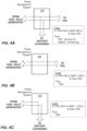
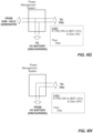
- FIGS 4A-4H each providing a simplified diagram depicting each of the various possible power flow combinations in the power supply interface 120 associated with the DC bus 125.
- FIGS. 4A-4C depict power flows for power supplied from the generator 162 and/or generator power converter 164 (e.g., second DC power).
- the power on the DC bus 125 is directed to the power management system 190 and thereby the TRU 26 and the energy storage system 150 for recharging the energy storage device 152.
- priority is given to satisfying the power requirements of the TRU 26. Any remaining power may be directed to the recharging application for the energy storage system 150.
- FIG 4B the figure depicts a second instance for power flows for power supplied from the generator 162 and/or generator power converter 164.
- the energy storage system 150 indicates that the energy storage device 152 is exhibiting a state of charge that is in excess of a selected threshold
- the power on the DC bus 125 is directed only to the power management system 190 to power only the TRU 26, (as the and the energy storage system 150 does not yet require recharging).
- FIG 4C a third power flow for power supplied from the generator 162 and/or generator power converter 164.
- the logic employed by the TRU controller 82 for directing the power to the power management system 190 addresses an instance when the TRU 26 is inoperative, and the energy storage system 150 indicates that the energy storage device 152 is exhibiting a state of charge that is less than a selected threshold (in this instance 100%, though other thresholds are possible).
- the DC power on the DC bus 125 is directed only to the energy storage system 150 for recharging the energy storage device 152.
- FIGS. 4D-4F depict power flows for power supplied from the grid power source 182.
- the logic employed by the TRU controller 82 for directing the power from the grid power source 182 determines if the TRU 26 is operating and the generator 162 (or the generator power converter 164) is inoperative. If so, and the energy storage system 150 indicates that the energy storage device 152 is exhibiting a charge state that is less than a selected threshold, then power is directed from the DC bus 125 to both the power management system 190 and then the TRU system 26 and the energy storage system 150 for recharging the energy storage device 152. In an embodiment, once again, priority is given to satisfying the power requirements of the TRU system 26.
- any remaining power may be directed to the recharging application for the energy storage system 150. It should be appreciated that while particular threshold of 80% is disclosed and employed for the described embodiments, such values and description are merely illustrative. Other values and applications for the thresholds are possible.
- FIG 4E the figure depicts a second instance for power flows for power supplied from the grid power source 182 when the generator 162 is inoperative.
- the DC power on the DC bus 125 is directed only to the power management system 190 directs and to the TRU 26, (as the energy storage system 150 does not yet require recharging).
- FIG 4F a third power flow for power supplied from the grid power source 182 when the generator 162 is inoperative.
- the logic employed by the TRU controller 82 for directing the power on the DC bus 125 addresses an instance when the TRU 26 is also inoperative, and the energy storage system 150 indicates that the energy storage device 152 is exhibiting a state of charge that is less than a selected threshold (in this instance 100%, though other thresholds are possible).
- the power on the DC bus 125 is directed only to the energy storage system 150 for recharging the energy storage device 152. In an embodiment, priority is given to satisfying the power requirements of energy storage system 150.
- the energy storage system 150 indicates that the energy storage device 152 is exhibiting a charge state of greater than a selected threshold
- power from both the generator 162 (or generator power converter 164) and the energy storage system 150 is directed to DC bus 125 and then to the power management system 190 and thereby the TRU 26.
- a threshold of 10 percent is employed for the state of charge of the energy storage device 152.
- power is provided by the energy storage system 150 and thereby discharging the energy storage device 152.
- priority is given to satisfying the power requirements of the TRU 26. This embodiment may be employed under conditions where the output power of the generator 162 and/or generator power converter 164 is less that that needed to operate the TRU 26.
- this embodiment may be employed under conditions where the output power of the generator 162 and/or generator power converter 164 is less that that needed to operate the TRU 26.
- threshold of 10% is disclosed and employed for the described embodiments, such values and description are merely illustrative. Other values and applications for the thresholds are possible. For example, in some instances it may be desirable prioritize operation of the TRU 26 such that fully draining the energy storage device 152 is acceptable. Likewise, in other embodiments, it may be desirable to modify the function or curtail the operation of the TRU to avoid excessively discharging the energy storage device 152.
- the power supply interface 120 is configured such that, in selected modes of operation power is directed to the TRU 26 from the tractor or vehicle 22.
- the energy storage device 152 exhibit a SOC below a selected threshold e.g., ⁇ 10% and the generator 162/generator power converter 164 is not operable but the TRU system 26 is operable and requires power
- TRU power could be drawn from the power system of the tractor or truck. (i.e. tie into the energy storage device or generator of the tractor/truck).
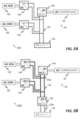
- FIG 5F depicts another simplified block diagram of the power supply interface 620 in accordance with still another embodiment as described herein.
- FIG. 5F depicts a configuration of the power supply interface 620 where the grid power supply 182 and grid power converter 184 as well as the generator 162 and the output of the generator power converter 164 are connected with the DC/DC converter 156 forming the fixed DC bus denoted once again 125c.
- DC/DC converter 156 of the energy storage system isolates the fixed DC bus 125c from the variable DC bus 125a.
- FIG 5G depicts a simplified block diagram of the power supply interface 720 in accordance with still yet another embodiment as described herein.
- FIG. 5G depicts a configuration of the power supply interface 720where the generator 162 and the output of the generator power converter 164 are connected with the energy storage device 152 on the variable DC bus 125a in a variable configuration.
- the DC/DC converter 156 of the energy storage system forming the fixed DC bus denoted once again 125c, once again DC/DC converter 156 isolates the fixed DC bus 125c from the variable DC bus 125a.
- the output of the DC/DC converter 156 of the energy storage system 150 is connected along with grid power converter 184 to fixed DC bus 125c, providing power the DC/AC converter 192 of the power management system 190 to provide power to the TRU system 26.
- the output of the DC/DC converter 156 of the energy storage system 150 is connected along with the energy storage device 152 on the variable DC bus 125a and providing power the DC/AC converter 192 of the power management system 190 to provide power to the TRU system 26.
- Embodiments can also be in the form of computer program code, for example, whether stored in a storage medium, loaded into and/or executed by a computer, or transmitted over some transmission medium, loaded into and/or executed by a computer, or transmitted over some transmission medium, such as over electrical wiring or cabling, through fiber optics, or via electromagnetic radiation, wherein, when the computer program code is loaded into an executed by a computer, the computer becomes a device for practicing the embodiments.
- the computer program code segments configure the microprocessor to create specific logic circuits.
Landscapes
- Engineering & Computer Science (AREA)
- Mechanical Engineering (AREA)
- Physics & Mathematics (AREA)
- Thermal Sciences (AREA)
- Power Engineering (AREA)
- Chemical & Material Sciences (AREA)
- Combustion & Propulsion (AREA)
- General Engineering & Computer Science (AREA)
- Transportation (AREA)
- Supply And Distribution Of Alternating Current (AREA)
Abstract
Description
- The subject matter disclosed herein generally relates to transportation refrigeration units, and more specifically to an apparatus and a method for powering transportation refrigeration unit with a generator and an energy storage device.
- Traditional refrigerated cargo trucks or refrigerated tractor trailers, such as those utilized to transport cargo via sea, rail, or road, is a truck, trailer or cargo container, generally defining a cargo compartment, and modified to include a refrigeration system located at one end of the truck, trailer, or cargo container. Refrigeration systems typically include a compressor, a condenser, an expansion valve, and an evaporator serially connected by refrigerant lines in a closed refrigerant circuit in accord with known refrigerant vapor compression cycles. A power unit, such as a combustion engine, drives the compressor of the refrigeration unit, and may be diesel powered, natural gas powered, or other type of engine. In many tractor trailer transport refrigeration systems, the compressor is driven by the engine shaft either through a belt drive or by a mechanical shaft-to-shaft link. In other systems, the engine of the refrigeration unit drives a generator that generates electrical power, which inturn drives the compressor.
- With current environmental trends, improvements in transportation refrigeration units are desirable particularly toward aspects of efficiency, sound and environmental impact. With environmentally friendly refrigeration units, improvements in reliability, cost, and weight reduction is also desirable.
- According to one embodiment, described herein is power system architectures configured to power a transport refrigeration system based on a determined an AC power requirement. The system includes a generator power converter configured to receive a generator three phase AC power from an alternating current (AC) generator operably coupled to an axle or wheel hub, and provide a generator DC power. The system also includes a grid power converter configured to receive a grid three phase AC power from a grid power source, the grid power converter operable to provide a grid DC power, an energy storage device, the energy storage device operable to provide a DC power and connected to a DC bus, and a power management system operably connected to direct power the transport refrigeration unit TRU based on at least the AC power requirement.
- In addition to one or more of the features described above, or as an alternative, further embodiments may include a DC/DC converter operably connected to a variable DC bus, the DC/DC converter configured to convert a variable DC power to a fixed DC power on a fixed DC bus.
- In addition to one or more of the features described above, or as an alternative, further embodiments may include that the generator power converter is configured to receive a first three phase AC power provided by the AC generator and transmit a generator DC power to one of a fixed DC bus or a variable DC bus.
- In addition to one or more of the features described above, or as an alternative, further embodiments may include that the generator power converter includes an AC/DC converter and the generator three phase AC power exhibits a first AC voltage and a first AC current, at a first frequency, and generator DC power exhibits a second DC voltage and a second DC current.
- In addition to one or more of the features described above, or as an alternative, further embodiments may include that the generator power converter includes a voltage control function, and a current control function, wherein at least the voltage control function is responsive at least in part to the AC power requirement.
- In addition to one or more of the features described above, or as an alternative, further embodiments may include that the grid power converter is configured to receive a first three phase AC power provided by the grid power source and transmit a grid DC power to one of a fixed DC bus or a variable DC bus.
- In addition to one or more of the features described above, or as an alternative, further embodiments may include that the grid power converter includes an AC/DC converter and the grid three phase AC power exhibits a grid AC voltage and a grid AC current, at a grid frequency, and grid DC power exhibits a grid DC voltage and a grid DC current.
- In addition to one or more of the features described above, or as an alternative, further embodiments may include that the grid power converter includes a voltage control function, and a current control function, wherein at least the voltage control function is responsive at least in part to the AC power requirement.
- In addition to one or more of the features described above, or as an alternative, further embodiments may include that the energy storage system includes an energy storage device and at least one of an first energy storage system DC/DC converter configured to provide DC power to the power management system based at least in part on the AC power requirement and a second energy storage system DC/DC converter configured to convert at least a portion of the DC power on the fixed DC bus to supply the variable DC bus and the energy storage device.
- In addition to one or more of the features described above, or as an alternative, further embodiments may include a battery management system operably connected to the TRU controller and configured to monitor at least a state of charge of the energy storage device.
- In addition to one or more of the features described above, or as an alternative, further embodiments may include that the energy storage system DC/DC converter and the second energy storage system DC/DC converter are integrated and wherein the first energy storage system DC/DC converter is operably connected to the TRU controller and configured to direct power flows to the fixed DC bus and the power management system and from the fixed DC bus to the variable DC bus based on at least one of the AC power requirement and the state of charge of the energy storage device.
- In addition to one or more of the features described above, or as an alternative, further embodiments may include that the energy storage device comprises at least one of a battery, fuel cell, and flow battery.
- In addition to one or more of the features described above, or as an alternative, further embodiments may include that the power management system is configured to receive a DC power from one of the fixed DC bus and the variable DC bus, and to provide a second three phase AC power to the TRU based at least on the AC power requirement.
- In addition to one or more of the features described above, or as an alternative, further embodiments may include that the power management system includes a DC/AC converter and the second three phase AC power exhibits a second three phase AC voltage and a second AC current, at a second frequency.
- In addition to one or more of the features described above, or as an alternative, further embodiments may include that the grid power converter, generator power converter, energy storage device, and power management system are operably connected to the variable DC bus.
- In addition to one or more of the features described above, or as an alternative, further embodiments may include that the grid power converter, generator power converter, the power management system, and energy storage system DC/DC converter are operably connected to the fixed DC bus, and the energy storage system DC/DC converter and energy storage device are operably connected to the variable DC bus.
- In addition to one or more of the features described above, or as an alternative, further embodiments may include that the grid power converter and power management system and energy storage system DC/DC converter are connected to the fixed DC bus, and the energy storage system DC/DC converter and generator power converter and energy storage device are operably connected to the variable DC bus.
- In addition to one or more of the features described above, or as an alternative, further embodiments may include that the grid power converter, the generator power converter, energy storage system DC/DC converter and energy storage device are connected to the variable DC bus, and the energy storage system DC/DC converter and the power management system are operably connected to the fixed DC bus.
- In addition to one or more of the features described above, or as an alternative, further embodiments may include that the grid power converter, power management system, the energy storage system DC/DC converter, and energy storage device are connected to the variable DC bus, and the energy storage system DC/DC converter and the generator power converter are operably connected to the fixed DC bus.
- In addition to one or more of the features described above, or as an alternative, further embodiments may include that the grid power converter, the generator power converter, the energy storage system DC/DC converter are connected to the fixed DC bus, and the energy storage system DC/DC converter, the energy storage device, and the power management system are operably connected to the variable DC bus.
- In addition to one or more of the features described above, or as an alternative, further embodiments may include that the grid power converter, and the energy storage system DC/DC converter are connected to the fixed DC bus, and the energy storage system DC/DC converter, the generator power converter, the energy storage device, and the power management system are operably connected to the variable DC bus.
- In addition to one or more of the features described above, or as an alternative, further embodiments may include that the generator power converter and power management system and energy storage system DC/DC converter are connected to the fixed DC bus, and the energy storage system DC/DC converter and grid power converter and energy storage device are operably connected to the variable DC bus.
- In addition to one or more of the features described above, or as an alternative, further embodiments may include a return air temperature (RAT) sensor disposed in the return airflow and configured measure the temperature of the return airflow, the RAT sensor operably connected to the TRU controller, the TRU controller configured to execute a process to determine the AC power requirement for the TRU based at least in part on the RAT.
- Also described herein in an embodiment is a method of generating and directing power to a transportation refrigeration unit system having a compressor configured to compress a refrigerant, an evaporator heat exchanger operatively coupled to the compressor; an evaporator fan configured to provide return airflow from a return air intake and flow the return airflow over the evaporator heat exchanger and a TRU controller operable to execute the method. The method includes determining an AC power requirement for the TRU, providing a generator DC power from a generator power converter operably connected an alternating current (AC) generator operably connected to an axle or wheel hub, and providing a grid DC power from a grid power converter operably connected to a grid power source providing a grid three phase AC power. The method also includes providing a DC power from a variable DC bus to a power management system, the variable DC bus operably connected an energy storage device and directing by a power management system, a three phase AC power the TRU, the power management system operably connected to the TRU, the directing based at least in part on the AC power requirement.
- In addition to one or more of the features described above, or as an alternative, further embodiments may include that the energy storage device includes a battery system.
- Technical effects of embodiments of the present disclosure include a transportation refrigeration unit coupled to and powered by an external generator system via a generator power converter, where the power generated by the generator and converted by the generator power converter is based on an AC power requirement of the transportation refrigeration unit.
- The foregoing features and elements may be combined in various combinations without exclusivity, unless expressly indicated otherwise. These features and elements as well as the operation thereof will become more apparent in light of the following description and the accompanying drawings. It should be understood, however, that the following description and drawings are intended to be illustrative and explanatory in nature and non-limiting.
- The subject matter which is regarded as the disclosure is particularly pointed out and distinctly claimed in the claims at the conclusion of the specification. The foregoing and other features and advantages of the disclosure are apparent from the following detailed description taken in conjunction with the accompanying drawings in which:
- The following descriptions should not be considered limiting in any way. With reference to the accompanying drawings, like elements are numbered alike:
-
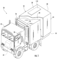
FIG. 1 is a perspective view of a transportation refrigeration system having a transportation refrigeration unit as one, non-limiting, according to an embodiment of the present disclosure; -
FIG. 2 is a schematic of the transportation refrigeration unit, according to an embodiment of the present disclosure; -
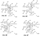
FIG. 3 is a block diagram of a transportation refrigeration unit and power system, according to an embodiment of the present disclosure; -
FIG. 4A depicts power flows of the power management system according to an embodiment of the present disclosure; -
FIG. 4B depicts power flows of the power management system, according to an embodiment of the present disclosure; -
FIG. 4C depicts power flows of the power management system, according to an embodiment of the present disclosure; -
FIG. 4D depicts power flows of the power management system, according to an embodiment of the present disclosure; -
FIG. 4E depicts power flows of the power management system , according to an embodiment of the present disclosure; -
FIG. 4F depicts power flows of the power management system , according to an embodiment of the present disclosure; -
FIG. 4G depicts power flows of the power management system , according to an embodiment of the present disclosure; -
FIG. 4H depicts power flows of the power management system , according to an embodiment of the present disclosure; -
FIG. 5A is a block diagram of a transportation refrigeration unit and power system, according to an embodiment of the present disclosure; -
FIG. 5B is a block diagram of a transportation refrigeration unit and power system, according to an embodiment of the present disclosure; -
FIG. 5C is a block diagram of a transportation refrigeration unit and power system, according to an embodiment of the present disclosure; -
FIG. 5D is a block diagram of a transportation refrigeration unit and power system, according to an embodiment of the present disclosure; -
FIG. 5E is a block diagram of a transportation refrigeration unit and power system, according to an embodiment of the present disclosure; -
FIG. 5F is a block diagram of a transportation refrigeration unit and power system, according to an embodiment of the present disclosure; -
FIG. 5G is a block diagram of a transportation refrigeration unit and power system, according to an embodiment of the present disclosure; and -
FIG. 5H is a block diagram of a transportation refrigeration unit and power system, according to an embodiment of the present disclosure. - A detailed description of one or more embodiments of the disclosed apparatus and method are presented herein by way of exemplification and not limitation with reference to the Figures.
- Referring to
FIG. 1 , atransport refrigeration system 20 of the present disclosure is illustrated. In the illustrated embodiment, thetransport refrigeration systems 20 may include a tractor orvehicle 22, acontainer 24, and an engineless transportation refrigeration unit (TRU) 26. Thecontainer 24 may be pulled by avehicle 22. It is understood that embodiments described herein may be applied to shipping containers that are shipped by rail, sea, air, or any other suitable container, thus the vehicle may be a truck, train, boat, airplane, helicopter, etc. - The
vehicle 22 may include an operator's compartment orcab 28 and acombustion engine 42 which is part of the powertrain or drive system of thevehicle 22. In some instances, thevehicle 22 may be a hybrid or all electric configuration having electric motors to provide propulsive force for the vehicle. In some configurations, theTRU system 26 may be engineless. In some embodiments, a small engine or the engine of thevehicle 22 may be employed to power or partially power theTRU 26. Thecontainer 24 may be coupled to thevehicle 22 and is thus pulled or propelled to desired destinations. The trailer may include atop wall 30, abottom wall 32 opposed to and spaced from thetop wall 30, twoside walls 34 spaced from and opposed to one-another, and opposing front andrear walls front wall 36 being closest to thevehicle 22. Thecontainer 24 may further include doors (not shown) at therear wall 38, or any other wall. Thewalls cargo compartment 40. Typically,transport refrigeration systems 20 are used to transport and distribute cargo, such as, for example perishable goods and environmentally sensitive goods (herein referred to as perishable goods). The perishable goods may include but are not limited to fruits, vegetables, grains, beans, nuts, eggs, dairy, seed, flowers, meat, poultry, fish, ice, blood, pharmaceuticals, or any other suitable cargo requiring cold chain transport. In the illustrated embodiment, theTRU 26 is associated with acontainer 24 to provide desired environmental parameters, such as, for example temperature, pressure, humidity, carbon dioxide, ethylene, ozone, light exposure, vibration exposure, and other conditions to thecargo compartment 40. In further embodiments, theTRU 26 is a refrigeration system capable of providing a desired temperature and humidity range. - Referring to
FIGS. 1 and2 , thecontainer 24 is generally constructed to store a cargo (not shown) in thecompartment 40. Theengineless TRU 26 is generally integrated into thecontainer 24 and may be mounted to thefront wall 36. The cargo is maintained at a desired temperature by cooling of thecompartment 40 via theTRU 26 that circulates refrigerated airflow into and through thecargo compartment 40 of thecontainer 24. It is further contemplated and understood that theTRU 26 may be applied to any transport compartments (e.g., shipping or transport containers) and not necessarily those used in tractor trailer systems. Furthermore, thetransport container 24 may be a part of the of thevehicle 22 or constructed to be removed from a framework and wheels (not shown) of thecontainer 24 for alternative shipping means (e.g., marine, railroad, flight, and others). - The components of the
engineless TRU 26 may include acompressor 58, anelectric compressor motor 60, acondenser 64 that may be air cooled, acondenser fan assembly 66, areceiver 68, afilter dryer 70, aheat exchanger 72, anexpansion valve 74, anevaporator 76, anevaporator fan assembly 78, asuction modulation valve 80, and acontroller 82 that may include a computer-based processor (e.g., microprocessor) and the like as will be described further herein. Operation of theengineless TRU 26 may best be understood by starting at thecompressor 58, where the suction gas (e.g., natural refrigerant, hydrofluorocarbon (HFC) R-404a, HFC R-134a... etc.) enters thecompressor 58 at asuction port 84 and is compressed to a higher temperature and pressure. The refrigerant gas is emitted from thecompressor 58 at anoutlet port 85 and may then flow into tube(s) 86 of thecondenser 64. - Air flowing across a plurality of condenser coil fins (not shown) and the
tubes 86, cools the gas to its saturation temperature. The air flow across thecondenser 64 may be facilitated by one ormore fans 88 of thecondenser fan assembly 66. Thecondenser fans 88 may be driven by respectivecondenser fan motors 90 of thefan assembly 66 that may be electric. By removing latent heat, the refrigerant gas within thetubes 86 condenses to a high pressure and high temperature liquid and flows to thereceiver 68 that provides storage for excess liquid refrigerant during low temperature operation. From thereceiver 68, the liquid refrigerant may pass through asub-cooler heat exchanger 92 of thecondenser 64, through the filter-dryer 70 that keeps the refrigerant clean and dry, then to theheat exchanger 72 that increases the refrigerant sub-cooling, and finally to theexpansion valve 74. - As the liquid refrigerant passes through the orifices of the
expansion valve 74, some of the liquid vaporizes into a gas (i.e., flash gas). Return air from the refrigerated space (i.e., cargo compartment 40) flows over the heat transfer surface of theevaporator 76. As the refrigerant flows through a plurality oftubes 94 of theevaporator 76, the remaining liquid refrigerant absorbs heat from the return air, and in so doing, is vaporized and thereby cools the return air. - The
evaporator fan assembly 78 includes one or moreevaporator fans 96 that may be driven byrespective fan motors 98 that may be electric. The air flow across theevaporator 76 is facilitated by theevaporator fans 96. From theevaporator 76, the refrigerant, in vapor form, may then flow through thesuction modulation valve 80, and back to thecompressor 58. Theexpansion valve 74 may be thermostatic or electrically adjustable. In an embodiment, as depicted, theexpansion valve 74 is thermostatic. A thermostatic expansionvalve bulb sensor 100 may be located proximate to an outlet of theevaporator tube 94. Thebulb sensor 100 is intended to control thethermostatic expansion valve 74, thereby controlling refrigerant superheat at an outlet of theevaporator tube 94. It is further contemplated and understood that the above generally describes a single stage vapor compression system that may be used for HFCs such as R-404a and R-134a and natural refrigerants such as propane and ammonia. Other refrigerant systems may also be applied that use carbon dioxide (CO2) refrigerant, and that may be a two-stage vapor compression system. In another embodiment, theexpansion valve 74 could be an electronic expansion valve. In this case the expansion valve is commanded to a selected position by thecontroller 82 based on the operating conditions of the vapor compression cycle and the demands of the system. - A bypass valve (not shown) may facilitate the flash gas of the refrigerant to bypass the
evaporator 76. This will allow the evaporator coil to be filled with liquid and completely 'wetted' to improve heat transfer efficiency. With CO2 refrigerant, this bypass flash gas may be re-introduced into a mid-stage of a two-stage compressor 58. - The
compressor 58 and thecompressor motor 60 may be linked via an interconnectingdrive shaft 102. Thecompressor 58, thecompressor motor 60 and thedrive shaft 102 may all be sealed within acommon housing 104. Thecompressor 58 may be a single compressor. The single compressor may be a two-stage compressor, a scroll-type compressor or other compressors adapted to compress HFCs or natural refrigerants. The natural refrigerant may be CO2, propane, ammonia, or any other natural refrigerant that may include a global-warming potential (GWP) of about one (1). - Continuing with
FIG.2 , and with continued reference toFIG. 1 ,FIG. 2 also illustrates airflow through theTRU 26 and thecargo compartment 40. Airflow is circulated into and through and out of thecargo compartment 40 of thecontainer 24 by means of theTRU 26. Areturn airflow 134 flows into theTRU 26 from thecargo compartment 40 through areturn air intake 136, and across theevaporator 76 via thefan 96, thus conditioning thereturn airflow 134 to a selected or predetermined temperature. The conditionedreturn airflow 134, now referred to as supply airflow 138, is supplied into thecargo compartment 40 of thecontainer 24 through therefrigeration unit outlet 140, which in some embodiments is located near thetop wall 30 of thecontainer 24. The supply airflow 138 cools the perishable goods in thecargo compartment 40 of thecontainer 24. It is to be appreciated that theTRU 26 can further be operated in reverse to warm thecontainer 24 when, for example, the outside temperature is very low. - A temperature sensor 142 (i.e., thermistor, thermocouples, RTD, and the like) is placed in the air stream, on the
evaporator 76, at thereturn air intake 136 , and the like, to monitor thetemperature return airflow 134 from thecargo compartment 40. A sensor signal indicative of the return airflow temperature denoted RAT is operably connected vialine 144 to theTRU controller 82 to facilitate control and operation of theTRU 26. Likewise, atemperature sensor 146 is placed in the supply airflow 138, on theevaporator 76, at therefrigeration unit outlet 140 to monitor the temperature of the supply airflow 138 directed into thecargo compartment 40. Likewise, a sensor signal indicative of the supply airflow temperature denoted SAT 14 is operably connected vialine 148 to theTRU controller 82 to facilitate control and operation of theTRU 26. - Referring now to
FIG. 3 , with continued reference toFIGs. 1 and2 as well, theTRU 26 may include or be operably interfaced with a power supply interface shown generally as 120. Thepower supply interface 120 may include, interfaces to/from various power sources denoted generally as 122 and more specifically as follows herein as well as one or more DC busses shown generally as 125 and more specifically 125a, 125b, ... 125n. In an embodiment, thepower sources 122 may include, but not be limited to anenergy storage device 152,generator 162, and grid power, 182. Each of thepower sources 122 may be configured to selectively power theTRU 26 as described further herein, includingcompressor motor 60, thecondenser fan motors 90, theevaporator fan motors 98, thecontroller 82, and other components 99 of theTRU 26 that may include various solenoids and/or sensors). Thecontroller 82 through a series of data and command signals overvarious pathways 108 may, for example, control the application of power to theelectric motors TRU 26. - The
engineless TRU 26 may include an AC or DC architecture with selected components employing alternating current (AC), and others employing direct current (DC). For example, in an embodiment, themotors motors power sources 122 as they supply power to theTRU 26 may be managed and monitored by theTRU controller 82 and interfaced from theDC bus 125 to thepower management system 190. Thepower management system 190 is configured direct the power from thevarious power sources 122, and the like, viaDC bus 125 based on various requirements of theTRU 26. In an embodiment, theTRU controller 82 receives various signals indicative of the operational state of theTRU 26 and determines the power requirements for theTRU system 26 accordingly and directs the components of thepower supply interface 120 and specifically thepower management system 190 to direct power accordingly to address the requirements of theTRU 26. - In one embodiment, the
TRU system 26 is controlled to a temperature setpoint value selected by the user. TheTRU controller 82 monitors the RAT and optionally the SAT as measured by thetemperature sensors TRU controller 82 estimates the power requirements for theTRU 26 based on the RAT (among others) and provides commands accordingly to the various components of thepower supply interface 120 and specifically thepower management system 190,energy storage system 150, andgenerator power converter 164 to manage the generation, conversion, and routing of power in thepower supply interface 120 andTRU system 26. By using the measured RAT and the setpoint value, an estimate to power demand is made. More specifically, in one embodiment, if the (RAT-setpoint value) is above a first threshold (e.g., > 10 degrees F), then full power (e.g., at a known voltage supply, current demand is known) is needed by theTRU system 26. If the (RAT-setpoint value) is between first threshold and second threshold, current requirement is limited (at known voltage) to achieve a mid-range power (e.g., ~50% power or something less than 100%). If the (RAT-setpoint value) is below second threshold, current is limited (at voltage) to achieve a minimum power (e.g., ~20% power). - The
TRU controller 82 is configured to control the components in theTRU 26 as well as the components of thepower supply interface 120 in accordance with operating needs of thetransport refrigeration system 20. TheTRU controller 82 is communicatively coupled to thepower management system 190, thegrid power source 182, theenergy storage system 150, and thegenerator power converter 164 orgenerator 162. For the TRU power demand, theTRU controller 82, using additional information from each of thepower sources 122 provides instructions to affect thegrid power source 182 output, thegenerator 162 andgenerator power converter 164 output, the charge/discharge of theenergy storage system 150, all to enable and configure providing power as required by theTRU 26. Additionally, theTRU controller 82 provides instructions for various components in thepower supply interface 120 to manage the power flow to theDC Bus 125 and thereby to thepower management system 190 depending upon the operational status of the various power sources (i.e.grid power 182,energy storage device 152 and generator 162) and as based on theTRU 26 power demand. - In an embodiment, the
power management system 190 includes a DC/AC converter 194. The DC/AC converter 194 is configured to receive DC power on theDC bus 125 denoted in thisinstance 125a (e.g., second DC voltage V2, a second DC current I2 from thegenerator power converter 165; and/or VG, IG 185; and/orDC voltage 155 from theenergy storage device 152; alone or as combined) and generate three phase AC power 195 (e.g., at AC voltage V2, AC current I2 a frequency f2), for providing power to theTRU system 26. In an embodiment, the DC/AC converter 194 includes a voltage control function, a current control function, and a frequency control function, each configured to facilitate the conversion. In an embodiment, theTRU controller 82 provides command signals denoted byline 191, to thepower management system 190. The commands are based, at least, on the power consumption requirements of theTRU 26 as discussed further herein. In addition, theTRU controller 82 may receive status information also depicted byline 191 regarding the DC/AC converter 194. In an embodiment, the communications may be over standard communication interfaces such as CAN, RS-485, and the like. Moreover, as is discussed further herein, the communications may be wired or wireless. - As described further herein, there are three
power sources 122grid power 182,generator 162/generator power converter 164 andenergy storage device 152. If theTRU 26 is "On" and operating, theTRU controller 82 knows, the power requirements for theTRU system 26, and thereby, what power is needed. TheTRU controller 82 is also programmed to ascertain whether or not grid power (e.g., 182) is available or not. If the grid power is available and TRU is On and energy storage device 152 (e.g., battery) SOC indicates a full charge, grid power will satisfyTRU system 26 power demand. Conversely, ifgrid power 182 is available and TRU On and the energy storage device is not fully charged, TRU power demand is satisfied as first priority and then DC/DC converter 156 is be activated to provide necessary charging toenergy storage device 152 as second priority. Moreover, ifgrid power 182 is available and TRU is "Off" and theenergy storage device 152 is not fully charged, the DC/DC converter156 will be activated to provide necessary charging current. Ifgrid power 182 is not available and generator/generator power converter 162/164 is not operable, all TRU power demand is satisfied by theenergy storage system 150 via theenergy storage device 152. Finally, ifgrid power 182 is not available and generator/generator power converter 162/164 is operable, then TRU power demand is satisfied by both thegenerator 162 &energy storage system 150. - As described herein, in operation, the
TRU controller 82 identifies the power requirements for theTRU 26 at least partially based on the RAT. TheTRU controller 82 conveys the power requirements to thepower management system 190 and/or thegenerator power converter 164 to convert the first threephase AC power 163 orfirst DC power 163a to thesecond DC power 165 as necessary to satisfy the requirements of theTRU 26 and theenergy storage system 150 and specifically the charging requirements of theenergy storage device 152. - The
DC bus 125 and thereby, thepower management system 190 may receive power from agrid power source 182 when it is available. In an embodiment thegrid power source 182 is interfaced to theDC bus 125 and thepower management system 190 via agrid power converter 184. In an embodiment, thepower management system 190 may be a stand-alone unit, or integral with theTRU 26. Thegrid power source 182 is generally conventional threephase AC power 220/480VAC at 60 or 400Hz. In an embodiment, thegrid power converter 184 is a conventional AC/DC converter operable to convert the three phase AC power from thegrid power source 182 to a DC voltage and current. Thegrid power converter 184 in one or more embodiments generates agrid DC power 185 including DC voltage VG, and DC current IG. Thegrid DC power 185 and is transmitted from thegrid power converter 184 to theDC bus 125 and thepower management system 190 or otherwise as described herein. - The
DC bus 125 andpower management system 190 receives power from agenerator 162 directly and/or via agenerator power converter 164. Thegenerator 162 can be axle or hub mounted configured to recover rotational energy when thetransport refrigeration system 20 is in motion and convert that rotational energy to electrical energy, such as, for example, when the axle of thevehicle 22 is rotating due to acceleration, cruising, or braking. In an embodiment, thegenerator 162 is configured to provide a first threephase AC power 163 comprising voltage V1, an AC current I1 at a given frequency f1 denoted byreference numeral 163. Thegenerator 162 may be asynchronous or synchronous. In another embodiment, thegenerator 162 may be DC, providing afirst DC power 163a including a DC voltage and DC current denoted as V1a, and DC current I1a. Thegenerator power converter 164 in one or more embodiments generates asecond DC power 165 including DC voltage V2, and DC current I2. Thesecond DC power 165 and is transmitted from thegenerator power converter 164 to theDC bus 125 and thereby thepower management system 190 or otherwise as described herein. - Continuing with
FIG. 3 and the architecture of thepower supply interface 120 and thevarious power sources 122 employed to power theTRU 26 and the components thereof. In an embodiment, one of thepower sources 122 may include, but not be limited to anenergy storage system 150 operably coupled to thepower management system 190. Theenergy storage system 150 transmitsDC power 155 viaDC bus 125b to, and receivesDC power 157 from theDC bus 125. Theenergy storage system 150 may include, but not be limited to theenergy storage device 152, and abattery management system 154. In an embodiment, thebattery management system 154 is a part of, and integral with, theenergy storage device 152. In thisembodiment DC bus - In an embodiment the DC voltages from the
power sources 122 includingDC voltage 185 from thegrid power source 182 and/or DC voltage V2, I2 165 from thegenerator power converter 164 combines to form the DC voltage on the and current onbus energy storage device 152 to the to charge and store energy on theenergy storage device 152. Conversely, in other embodiments, for example whengrid power source 182 is not available, theenergy storage device 152 supplies DC voltage and current 155 directly to theDC bus power management system 190 for powering theTRU 26. In another embodiment, theenergy storage system 150 further includes a DC/DC converter 156. In one embodiment, theDC bus 125, and more specifically 125a providesDC power 157 to a DC/DC converter 156 to formulate a DC voltage and current 155 onDC bus 125b to charge and store energy on theenergy storage device 152. Conversely, in other embodiments theenergy storage device 152 supplies DC voltage and current 155 viaDC bus 125b to the DC/DC converter 156 operating as a DC/DC converter to supply aDC power 157 to theDC bus power management system 190 for powering theTRU 26. It should be appreciated that as described herein, the DC/DC converter 156 is bidirectional, enabling conversions in both directions to facilitate charging and discharging theenergy storage device 152. While the DC/DC converter 156 is described as bidirectional, such description is merely for the purposes of illustration. In operation, the DC/DC converter 156 may be a single integrated unit, or multiple units configured in parallel to operate in opposite directions. It is also noteworthy to appreciate that in the various embodiments described herein, numerous architectures are described based on the interconnection between thevarious power sources 122. More specifically, the interconnection betweenpower sources 122, e.g.,grid power source 182,generator 162 and the DC/AC converter 194 of thepower management system 190 with theenergy storage device 152, based on the optional application of the optional DC/DC converter 156. In the various architectures, where theenergy storage device 152 is directly connected (e.g. 125a directly connected to 125b), that portion of the bus is termed variable as the voltage is capable of variation based on the state of charge of theenergy storage device 152. On the other hand, in the instances where the DC/DC converter is employed, the portions of the DC bus directly connected (e.g., 125b) to theenergy storage device 152 and at the input connection to the DC/DC converter are considered variable, while the portion at the output of the DC/DC converter 156 connected to theDC bus 125, (e.g., 125a) are considered fixed and regulated. - The
battery management system 154 monitors the performance of theenergy storage device 152. For example, monitoring the state of charge of theenergy storage device 152, a state of health of theenergy storage device 152, and a temperature of theenergy storage device 152. Examples of theenergy storage device 152 may include a battery system (e.g., a battery or bank of batteries), fuel cells, flow battery, ultracapacitors, and others devices capable of storing and outputting electric energy that may be direct current (DC). Theenergy storage device 152 may include a battery system, which may employ multiple batteries organized into battery banks. - If the
energy storage system 150 includes a battery system for theenergy storage device 152, the battery system may have a voltage potential within a range of about two-hundred volts (200V) to about six-hundred volts (600V). Generally, the higher the voltage, the greater is the sustainability of electric power which is preferred. However, with increases in the voltage, the size and weight of the battery/batteries in anenergy storage device 152 increase. Increased size and weight are generally not preferred when transporting cargo. Additionally, if theenergy storage device 152 is a battery, then in order to increase either voltage and/or current, the batteries need to be connected in series or parallel depending upon electrical needs. Higher voltages in a batteryenergy storage device 152 will require more batteries in series than lower voltages, which in turn results in bigger and heavier batteryenergy storage device 152. A lower voltage and higher current system may be used, however such a system may require larger cabling or bus bars. As a result, commonly the selection and integration of theenergy storage device 152, in a power system requires tradeoffs between capacity current, size weight and the like. In addition, the voltage and current capability of theenergy storage device 152 may also require tradeoffs on the architecture of the power system such as direct connection or employing a DC/DC converter as described herein. - In one embodiment, the
energy storage device 152 may be contained within the structure 27 of theTRU 26. In an embodiment, theenergy storage device 152 is located with theTRU 26, however, other configurations are possible. In another embodiment, theenergy storage device 152 may be located with thecontainer 24 such as, for example, underneath thecargo compartment 40. Likewise, the DC/DC converter 156 may be located with thecontainer 24 such as, for example, underneath thecargo compartment 40, however, in some embodiments it may be desirable to have the DC/DC converter 156 in close proximity to thepower management system 190 and/or theTRU 26 andTRU controller 82. It will be appreciated that in one or more embodiments, while particular locations are described with respect to connection and placement of selected components including theenergy storage device 152 and/or DC/DC converter 156, such descriptions are merely illustrative and are not intended to be limiting. Varied location, arrangement and configuration of components is possible and within the scope of the disclosure. - The
battery management system 154 and DC/DC converter 156 are operably connected to and interface with theTRU controller 82. TheTRU controller 82 receives information regarding the status ofenergy storage system 150, including theenergy storage device 152 to provide control inputs to the DC/DC converter 156 to monitor theenergy storage device 152, as well as control charge and discharge rates for theenergy storage device 152. - In an embodiment associated with the
generator power converter 164 is an AC/DC converter and configured to receive the three phase AC power 163 (e.g., at AC voltage V1, AC current I1 a frequency f1), from thegenerator 162 and convert it to a DC power denoted 165 comprising a second DC voltage V2, a second DC current I2. Thesecond DC power 165 is transmitted from thegenerator power converter 164 to theDC bus 125 andpower management system 190. In an embodiment, thegenerator power converter 164 is configured to provide thesecond DC power 165 based of the requirements of theTRU 26. In an embodiment, thegenerator power converter 164 includes avoltage control function 166, acurrent control function 167, are each configured to facilitate the conversion. In an embodiment, theTRU controller 82 provides command signals denoted 169, and 170 to avoltage control function 166,current control function 167, respectively. The command signals 169, and 170 are generated by theTRU controller 82 based on the power consumption requirements of theTRU 26 as discussed further herein. In addition, theTRU controller 82 may receive status information as depicted by 171, 172 regarding thegenerator power converter 164, andgenerator 162 respectively. Likewise, the generator power converter may receive control signal or provide status signals toTRU controller 82, thepower management system 190, orenergy storage system 150 for mode selection and diagnostic purposes. In an embodiment, the communications may be over standard communication interfaces such as CAN, RS-485, and the like. Moreover, as is discussed further herein, the communications may be wired or wireless. - In this embodiment, the
generator power converter 164, thevoltage control function 166 includes a voltage regulation function and is configured to monitor the output voltage from thegenerator 162 and maintains a constant DC voltage out of thevoltage control function 166. Thevoltage control function 166 communicates status to theTRU Controller 82. Thecurrent control function 167 monitors and communicates to theTRU 26 the status of current draw from thegenerator 162. In an embodiment, the current may be limited depending on the power demands of theTRU 26. Finally, in an embodiment a frequency converter function 168 may also monitors the frequency of the threephase power 163 produced by thegenerator 162 to facilitate the conversion of the threephase power 163 to thesecond DC power 165 as determined by thevoltage control function 166 and theTRU controller 82 for supply to thepower management system 190 and ultimately theTRU 26. Thegenerator power converter 164 may be a stand-alone unit configured to be in close proximity to or even integral with thegenerator 162. - In yet another embodiment, for example, when the
generator 162 is a DC generator, thegenerator power converter 164 is an DC/DC converter and configured to receiveDC power 163a (e.g., at DC voltage V1a, DC current I1a), from thegenerator 162 and convert it to the second DC power denoted 165a comprising a second DC voltage V2a, a second DC current I2a. The second DC power 165a is transmitted from thegenerator power converter 164 to thepower management system 190. Once again, as described above, thegenerator power converter 164 is configured to provide the second DC power 165a based of the requirements of theTRU 26 as described above. In this embodiment, thegenerator power converter 164 including thevoltage control function 166, and thecurrent control function 167, are each configured to facilitate the DC/DC conversion. In this embodiment, once again theTRU controller 82 provides command signals denoted 169, and 170 to avoltage control function 166,current control function 167 respectively, based on the power consumption requirements of theTRU 26 as discussed further herein. In this embodiment, thevoltage control function 166 includes a voltage regulation function and is configured to monitor the output DC voltage from thegenerator 162 and maintains a constant DC voltage out of thevoltage control function 166 for supply to theDC bus 125 andpower management system 190 and ultimately theTRU 26. Thecurrent control function 167 monitors and communicates to theTRU 26 the status of current draw from thegenerator 162. Once again, in an embodiment, the communications may be over standard communication interfaces such as CAN, RS-485, and the like. Moreover, as is discussed further herein, the communications may be wired or wireless. - Continuing with
FIG. 3 , as described earlier, thepower supply interface 120 may include, interfaces tovarious power sources 122 managed and monitored by theTRU controller 82. TheTRU controller 82 and thepower management system 190 manages and determines electrical power flows in thepower supply interface 120 based upon the operational needs of theTRU 26 and the capabilities of the components in thepower supply interface 120, (e.g.,generator 162,converter 164,energy storage device 152, and the like. The TRU controller determines the status ofvarious power sources 122, controls their operation, and directs the power to and from thevarious power sources 122 and the like based on various requirements of theTRU 26. - In an embodiment there are five primary power flows associated with the
power supply interface 120 and specifically theDC bus 125 managed by theTRU controller 82 and thepower management system 190. First, the power into the /dc bus 125 supplied via thegenerator 162 orgenerator power converter 164, e.g., second DC power 165). Second, the power supplied to theDC bus 125 when operably connected togrid power source 182. Third the power supplied to the DC bus from anenergy storage device 152. Fourth, the power directed from theDC bus 125 to theenergy storage device 152. Finally, the DC power directed to thepower management system 190 andTRU 26 from theDC bus 125. - The power flows will be transferred through different paths based on the requirements placed on the
power management system 190 and particular configuration of thepower supply interface 120. TheDC bus 125 and thepower management system 190 operates as a central power bus to connectvarious power sources 122 together to supply the power needs of theTRU 26. The TRU controller andpower management system 190 controls switching, directing, or redirecting power to/from the five power flows as needed to satisfy the power requirements of theTRU 26. - Turning now to
FIGS 4A-4H each providing a simplified diagram depicting each of the various possible power flow combinations in thepower supply interface 120 associated with theDC bus 125.FIGS. 4A-4C depict power flows for power supplied from thegenerator 162 and/or generator power converter 164 (e.g., second DC power). Referring now toFIG 5A , in an embodiment, the logic employed by theTRU controller 82 for directing the power on theDC bus 125 and to thepower management system 190 if theTRU 26 is operating. If so, and theenergy storage system 150 indicates that theenergy storage device 120 is exhibiting a charge state that is less than a selected threshold, then the power on theDC bus 125 is directed to thepower management system 190 and thereby theTRU 26 and theenergy storage system 150 for recharging theenergy storage device 152. In an embodiment, priority is given to satisfying the power requirements of theTRU 26. Any remaining power may be directed to the recharging application for theenergy storage system 150. It should be appreciated that while particular threshold of 80% is disclosed and employed for the described embodiments, such values and description are merely illustrative. Other values and applications for the thresholds are possible. - Referring now to
FIG 4B as well, the figure depicts a second instance for power flows for power supplied from thegenerator 162 and/orgenerator power converter 164. In this embodiment, if theTRU 26 is operating, and theenergy storage system 150 indicates that theenergy storage device 152 is exhibiting a state of charge that is in excess of a selected threshold, then the power on theDC bus 125 is directed only to thepower management system 190 to power only theTRU 26, (as the and theenergy storage system 150 does not yet require recharging). Similarly, in yet another embodiment, as depicted byFIG 4C , a third power flow for power supplied from thegenerator 162 and/orgenerator power converter 164. In this embodiment, the logic employed by theTRU controller 82 for directing the power to thepower management system 190 addresses an instance when theTRU 26 is inoperative, and theenergy storage system 150 indicates that theenergy storage device 152 is exhibiting a state of charge that is less than a selected threshold (in thisinstance 100%, though other thresholds are possible). In this embodiment, the DC power on theDC bus 125 is directed only to theenergy storage system 150 for recharging theenergy storage device 152. - Turning now to
FIGS. 4D-4F , which depict power flows for power supplied from thegrid power source 182. In an embodiment as depicted inFIG 4D , the logic employed by theTRU controller 82 for directing the power from thegrid power source 182 determines if theTRU 26 is operating and the generator 162 (or the generator power converter 164) is inoperative. If so, and theenergy storage system 150 indicates that theenergy storage device 152 is exhibiting a charge state that is less than a selected threshold, then power is directed from theDC bus 125 to both thepower management system 190 and then theTRU system 26 and theenergy storage system 150 for recharging theenergy storage device 152. In an embodiment, once again, priority is given to satisfying the power requirements of theTRU system 26. Any remaining power may be directed to the recharging application for theenergy storage system 150. It should be appreciated that while particular threshold of 80% is disclosed and employed for the described embodiments, such values and description are merely illustrative. Other values and applications for the thresholds are possible. - Referring now to
FIG 4E as well, the figure depicts a second instance for power flows for power supplied from thegrid power source 182 when thegenerator 162 is inoperative. In this embodiment, if theTRU 26 is operating, and theenergy storage system 150 indicates that theenergy storage device 152 is exhibiting a state of charge that is in excess of a selected threshold, then the DC power on theDC bus 125 is directed only to thepower management system 190 directs and to theTRU 26, (as theenergy storage system 150 does not yet require recharging). Similarly, in yet another embodiment, as depicted byFIG 4F , a third power flow for power supplied from thegrid power source 182 when thegenerator 162 is inoperative. In this embodiment, the logic employed by theTRU controller 82 for directing the power on theDC bus 125 addresses an instance when theTRU 26 is also inoperative, and theenergy storage system 150 indicates that theenergy storage device 152 is exhibiting a state of charge that is less than a selected threshold (in thisinstance 100%, though other thresholds are possible). In this embodiment, the power on theDC bus 125 is directed only to theenergy storage system 150 for recharging theenergy storage device 152. In an embodiment, priority is given to satisfying the power requirements ofenergy storage system 150. - Turning now
FIGS. 4G and 4H , which depict power flows for power supplied to thepower management system 190 and theTRU 26 under selected conditions for operating from theenergy storage system 150 as well. InFIG. 4G power flows to theTRU 26 are provided from thegenerator 162 and/or generator power converter 164 (e.g., second DC power 165) as well as from theenergy storage system 150. In an embodiment, the logic employed by theTRU controller 82 for directing the power to theDC bus 125 and thepower management system 190 determines if theTRU 26 is operating. If so, and theenergy storage system 150 indicates that theenergy storage device 152 is exhibiting a charge state of greater than a selected threshold, then power from both the generator 162 (or generator power converter 164) and theenergy storage system 150 is directed toDC bus 125 and then to thepower management system 190 and thereby theTRU 26. In an embodiment, a threshold of 10 percent is employed for the state of charge of theenergy storage device 152. In this embodiment, power is provided by theenergy storage system 150 and thereby discharging theenergy storage device 152. In an embodiment, priority is given to satisfying the power requirements of theTRU 26. This embodiment may be employed under conditions where the output power of thegenerator 162 and/orgenerator power converter 164 is less that that needed to operate theTRU 26. It should be appreciated that while particular threshold of 10% is disclosed and employed for the described embodiments, such values and description are merely illustrative. Other values and applications for the thresholds are possible. For example, in some instances it may be desirable prioritize operation of theTRU 26 such that fully draining theenergy storage device 152 is acceptable. Likewise, in other embodiments, it may be desirable to modify the function or curtail the operation of theTRU 26 to avoid excessively discharging theenergy storage device 152. - Referring now to
FIG 4H as well, the figure depicts a second instance for power flows from theenergy storage system 150 alone. In this embodiment, if theTRU 26 is operating, but thegenerator 162 and/or thegenerator power converter 164 is inoperative, if theenergy storage system 150 indicates that theenergy storage device 152 is exhibiting a state of charge that is in excess of a selected threshold, then the power on the DC bus is directed to thepower management system 190, which then provides power to theTRU 26. In an embodiment a threshold of 10 percent is employed for the state of charge of theenergy storage device 152. In this embodiment, power is provided by theenergy storage system 150 and thereby discharging theenergy storage device 152. In an embodiment, priority is given to satisfying the power requirements of theTRU 26. Once again, this embodiment may be employed under conditions where the output power of thegenerator 162 and/orgenerator power converter 164 is less that that needed to operate theTRU 26. It should be appreciated that while particular threshold of 10% is disclosed and employed for the described embodiments, such values and description are merely illustrative. Other values and applications for the thresholds are possible. For example, in some instances it may be desirable prioritize operation of theTRU 26 such that fully draining theenergy storage device 152 is acceptable. Likewise, in other embodiments, it may be desirable to modify the function or curtail the operation of the TRU to avoid excessively discharging theenergy storage device 152. - Returning to
FIG. 3 , in another embodiment and specialized mode of operation and power flow for theTRU system 26 and thepower supply interface 120. In this embodiment, referred to as a fail operational or "limp home" mode, thepower supply interface 120 is configured such that, in selected modes of operation power is directed to theTRU 26 from the tractor orvehicle 22. In an embodiment, should theenergy storage device 152 exhibit a SOC below a selected threshold e.g., <10% and thegenerator 162/generator power converter 164 is not operable but theTRU system 26 is operable and requires power, TRU power could be drawn from the power system of the tractor or truck. (i.e. tie into the energy storage device or generator of the tractor/truck). Moreover, it should be appreciated that the described embodiments while generally referring thegenerator 162 being installed on the trailer portion of the vehicle, 22, such description is merely illustrative. In another embodiment, thegenerator 162 or another generator could be installed at a hub or axle of the tractor portion of thevehicle 22 without loss of generality and still be fully applicable to the described embodiments. In an embodiment, the tractor/truck power may be routed to thepower supply interface 120 through a grid plug 189. Alternately connectable between thegrid power source 182 and the vehicle power. For example, in operation, whenvehicle 22 trailer is in operation, for example, on delivery, grid plug 189 would be plugged into the tractor/trailer's electric PTO and act as mobile grid source. TheTRU controller 82 would be programmed to determine if the grid plug is active and if so, to pull power (or supplement generator power) only if energy storage device SOC is below threshold as alternative to modify the function or curtail the operation of theTRU system 26. - Turning now to
FIGS 5A-5H, FIGS 5A-5H depict a plurality of possible configurations for thepower supply interface 120.FIG 5A depicts a simplified block diagram of thepower supply interface 120 as described herein.FIG. 5A depicts thesingle DC bus 125 in a variable configuration.FIG. 5B depicts the alternate embodiment of thepower supply interface 220 as described above. In this embodiment, the DC bus is split with avariable side 125b between theenergy storage device 152 and the DC/DC converter 156 and a fixedDC bus DC converter 156 of theenergy storage system 150. -
FIG 5C depicts a simplified block diagram of thepower supply interface 320 in accordance with another embodiment as described herein.FIG. 5C depicts a configuration of thepower supply interface 320 where thegrid power supply 182 andgrid power converter 184 are commonly connected with theenergy storage device 152 on theDC bus 125b in a variable configuration. In this embodiment the DC/DC converter 156 isolates thevariable DC bus 125b from the fixedDC bus 125a which includes the output of the DC/DC converter 156 of theenergy storage system 150 and the output of thegenerator power converter 164 commonly connected with the DC/AC converter 192 of thepower management system 190 to provide power to theTRU system 26. - Similarly,
FIG 5D depicts a simplified block diagram of thepower supply interface 420 in accordance with yet another embodiment as described herein.FIG. 5D depicts a configuration of thepower supply interface 420 where thegrid power supply 182 andgrid power converter 184 are commonly connected with thegenerator 162 and the output of thegenerator power converter 164 withenergy storage device 152 on theDC bus 125b in a variable configuration. In this embodiment the DC/DC converter 156 isolates thevariable DC bus 125b from the fixedDC bus 125a which includes the output of the DC/DC converter 156 of theenergy storage system 150 commonly connected with the DC/AC converter 192 of thepower management system 190 to provide power to theTRU system 26. - Likewise,
FIG 5E depicts a simplified block diagram of thepower supply interface 520 in accordance with yet another embodiment as described herein.FIG. 5E depicts a configuration of thepower supply interface 520 where thegrid power supply 182 andgrid power converter 184 are connected in series with the DC/DC converter 156 forming the fixed DC bus denoted 125c between the grid power converter and the DC/DC converter 156 of theenergy storage system 150. In this embodiment the DC/DC converter 156 isolates the fixedDC bus 125c from thevariable DC bus 125a. Thegenerator 162 and the output of thegenerator power converter 164 along with theenergy storage device 152 are connected on thevariable DC bus 125a in a variable configuration with the DC/AC converter 192 of thepower management system 190 to provide power to theTRU system 26. - Likewise,
FIG 5F depicts another simplified block diagram of thepower supply interface 620 in accordance with still another embodiment as described herein.FIG. 5F depicts a configuration of thepower supply interface 620 where thegrid power supply 182 andgrid power converter 184 as well as thegenerator 162 and the output of thegenerator power converter 164 are connected with the DC/DC converter 156 forming the fixed DC bus denoted once again 125c. Once again DC/DC converter 156 of the energy storage system isolates the fixedDC bus 125c from thevariable DC bus 125a. In addition, the output of the DC/DC converter 156 of theenergy storage system 150 is connected along with theenergy storage device 152 on thevariable DC bus 125a in a variable configuration with the DC/AC converter 192 of thepower management system 190 to provide power to theTRU system 26. - Likewise,
FIG 5G depicts a simplified block diagram of the power supply interface 720 in accordance with still yet another embodiment as described herein.FIG. 5G depicts a configuration of the power supply interface 720where thegenerator 162 and the output of thegenerator power converter 164 are connected with theenergy storage device 152 on thevariable DC bus 125a in a variable configuration. The DC/DC converter 156 of the energy storage system forming the fixed DC bus denoted once again 125c, once again DC/DC converter 156 isolates the fixedDC bus 125c from thevariable DC bus 125a. In addition, the output of the DC/DC converter 156 of theenergy storage system 150 is connected along withgrid power converter 184 to fixedDC bus 125c, providing power the DC/AC converter 192 of thepower management system 190 to provide power to theTRU system 26. - Finally,
FIG 5H depicts a simplified block diagram of thepower supply interface 820 in accordance with still yet another embodiment as described herein.FIG. 5G depicts a configuration of thepower supply interface 820 where thegenerator 182 is connected to thegenerator power converter 184 to a fixedvoltage DC bus 125c. Thegrid power source 182 via the output of thegrid power converter 184 is connected with theenergy storage device 152 on thevariable DC bus 125a in a variable configuration. The DC/DC converter 156 of theenergy storage system 150 is connected to thegenerator power converter 164 on the fixedDC bus 125c. Once again DC/DC converter 156 isolates the fixedDC bus 125c from thevariable DC bus 125a. In addition, the output of the DC/DC converter 156 of theenergy storage system 150 is connected along with theenergy storage device 152 on thevariable DC bus 125a and providing power the DC/AC converter 192 of thepower management system 190 to provide power to theTRU system 26. - The
TRU 26 may further include a renewable power source 110 (FIG. 1 ) configured to recharge the batteries of theenergy storage device 152. One embodiment of arenewable power source 110 may be solar panels mounted, for example, to the outside of thetop wall 30 of the container 24 (also seeFIG. 1 ). For example therenewable power source 110 could generate all or a portion of the needed low voltage DC power for theTRU controller 82. Once again, such a configuration simplifies the wiring and routing of the system design by eliminating an additional set of DC cabling from theenergy storage device 152 beyond the HV cabling going toe the AC/DC converter 156. - Benefits of the present disclosure when compared to more traditional systems include no fuel carriage, fuel system and fuel consumption, and a refrigeration unit that emits less noise and no combustion byproducts. Yet further, the present disclosure includes an energy storage device that is conveniently and efficiently recharged to meet the power demands of the refrigeration unit.
- As described above, embodiments can be in the form of processor-implemented processes and devices for practicing those processes, such as a processor. Embodiments can also be in the form of computer program code containing instructions embodied in tangible media, such as network cloud storage, SD cards, flash drives, floppy diskettes, CD ROMs, hard drives, or any other computer-readable storage medium, wherein, when the computer program code is loaded into and executed by a computer, the computer becomes a device for practicing the embodiments. Embodiments can also be in the form of computer program code, for example, whether stored in a storage medium, loaded into and/or executed by a computer, or transmitted over some transmission medium, loaded into and/or executed by a computer, or transmitted over some transmission medium, such as over electrical wiring or cabling, through fiber optics, or via electromagnetic radiation, wherein, when the computer program code is loaded into an executed by a computer, the computer becomes a device for practicing the embodiments. When implemented on a general-purpose microprocessor, the computer program code segments configure the microprocessor to create specific logic circuits.
- The term "about" is intended to include the degree of error associated with measurement of the particular quantity based upon the equipment available at the time of filing the application. For example, "about" can include a range of ± 8% or 5%, or 2% of a given value.
- The terminology used herein is for the purpose of describing particular embodiments only and is not intended to be limiting of the present disclosure. As used herein, the singular forms "a", "an" and "the" are intended to include the plural forms as well, unless the context clearly indicates otherwise. It will be further understood that the terms "comprises" and/or "comprising," when used in this specification, specify the presence of stated features, integers, steps, operations, elements, and/or components, but do not preclude the presence or addition of one or more other features, integers, steps, operations, element components, and/or groups thereof.
- While the present disclosure has been described with reference to an exemplary embodiment or embodiments, it will be understood by those skilled in the art that various changes may be made and equivalents may be substituted for elements thereof without departing from the scope of the present disclosure. In addition, many modifications may be made to adapt a particular situation or material to the teachings of the present disclosure without departing from the essential scope thereof. Therefore, it is intended that the present disclosure not be limited to the particular embodiment disclosed as the best mode contemplated for carrying out this present disclosure, but that the present disclosure will include all embodiments falling within the scope of the claims.
- The following clauses set out aspects of the invention that may or may not presently be claimed, but which may form the basis for future amendment or a divisional application.
- 1. A power system architecture for powering a transportation refrigeration system comprising:
- a transport refrigeration unit (TRU) operable in a vapor compression cycle, the TRU having a compressor configured to compress a refrigerant, an evaporator heat exchanger operatively coupled to the compressor, an evaporator fan configured to provide return airflow from a return air intake and flow the return airflow over the evaporator heat exchanger, the TRU also including a TRU controller configured to execute a process to determine an AC power requirement for the TRU;
- a generator power converter configured to receive the generator three phase AC power from an alternating current (AC) generator operably coupled to an axle or wheel hub, and configured to provide a generator three phase AC power and provide a generator DC power;
- a grid power converter configured to receive the grid three phase AC power from a grid power source operable to provide the grid three phase AC power; the grid power converter operable to provide a grid DC power;
- an energy storage device, the energy storage device operable to provide a DC power and connected to a variable DC bus;
- a power management system operably connected to direct power the TRU based at least in part on at least the AC power requirement.
- 2. The power system architecture of
clause 1, further including a DC/DC converter operably connected to a variable DC bus, the DC/DC converter configured to convert a variable DC power to a fixed DC power on a fixed DC bus. - 3. The power system architecture of
clause 1, wherein the generator power converter is configured to receive a first three phase AC power provided by the AC generator and transmit a generator DC power to one of a fixed DC bus or a variable DC bus. - 4. The power system architecture of
clause 1, wherein the generator power converter includes an AC/DC converter and the generator three phase AC power exhibits a first AC voltage and a first AC current, at a first frequency, and generator DC power exhibits a second DC voltage and a second DC current. - 5. The power system architecture of
clause 1, wherein the generator power converter includes a voltage control function, and a current control function, wherein at least the voltage control function is responsive at least in part to the AC power requirement. - 6. The power system architecture of
clause 1, wherein the grid power converter is configured to receive a first three phase AC power provided by the grid power source and transmit a grid DC power to one of a fixed DC bus or a variable DC bus. - 7. The power system architecture of
clause 1, wherein the grid power converter includes an AC/DC converter and the grid three phase AC power exhibits a grid AC voltage and a grid AC current, at a grid frequency, and grid DC power exhibits a grid DC voltage and a grid DC current. - 8. The power system architecture of
clause 1, wherein the grid power converter includes a voltage control function, and a current control function, wherein at least the voltage control function is responsive at least in part to the AC power requirement. - 9. The power system architecture of clause 2, wherein the energy storage system includes an energy storage device and at least one of an first energy storage system DC/DC converter configured to provide DC power to the power management system based at least in part on the AC power requirement and a second energy storage system DC/DC converter configured to convert at least a portion of the DC power on the fixed DC bus to supply the variable DC bus and the energy storage device.
- 10. The power system architecture of clause 9, further including a battery management system operably connected to the TRU controller and configured to monitor at least a state of charge of the energy storage device.
- 11. The power system architecture of
clause 10, wherein the energy storage system DC/DC converter and the second energy storage system DC/DC converter are integrated and wherein the first energy storage system DC/DC converter is operably connected to the TRU controller and configured to direct power flows to the fixed DC bus and the power management system and from the fixed DC bus to the variable DC bus based on at least one of the AC power requirement and the state of charge of the energy storage device. - 12. The power system architecture of
clause 1, wherein the energy storage device comprises at least one of a battery, fuel cell, and flow battery. - 13. The power system architecture of clause 2, wherein the power management system is configured to receive a DC power from one of the fixed DC bus and the variable DC bus, and to provide a second three phase AC power to the TRU based at least on the AC power requirement.
- 14. The power system architecture of
clause 1, wherein the power management system includes a DC/AC converter and the second three phase AC power exhibits a second three phase AC voltage and a second AC current, at a second frequency. - 15. The power system architecture of
clause 1, wherein the grid power converter, generator power converter, energy storage device, and power management system are operably connected to the variable DC bus. - 16. The power system architecture of
clause 1, wherein the grid power converter, generator power converter, the power management system, and energy storage system DC/DC converter are operably connected to the fixed DC bus, and the energy storage system DC/DC converter and energy storage device are operably connected to the variable DC bus. - 17. The power system architecture of
clause 1, wherein the grid power converter and power management system and energy storage system DC/DC converter are connected to the fixed DC bus, and the energy storage system DC/DC converter and generator power converter and energy storage device are operably connected to the variable DC bus. - 18. The power system architecture of
clause 1, wherein the grid power converter, the generator power converter, energy storage system DC/DC converter and energy storage device are connected to the variable DC bus, and the energy storage system DC/DC converter and the power management system are operably connected to the fixed DC bus. - 19. The power system architecture of
clause 1, wherein the grid power converter, power management system, the energy storage system DC/DC converter, and energy storage device are connected to the variable DC bus, and the energy storage system DC/DC converter and the generator power converter are operably connected to the fixed DC bus. - 20. The power system architecture of
clause 1, wherein the grid power converter, the generator power converter, the energy storage system DC/DC converter are connected to the fixed DC bus, and the energy storage system DC/DC converter, the energy storage device, and the power management system are operably connected to the variable DC bus. - 21. The power system architecture of
clause 1, wherein the grid power converter, and the energy storage system DC/DC converter are connected to the fixed DC bus, and the energy storage system DC/DC converter, the generator power converter, the energy storage device, and the power management system are operably connected to the variable DC bus. - 22. The power system architecture of
clause 1, wherein the generator power converter and power management system and energy storage system DC/DC converter are connected to the fixed DC bus, and the energy storage system DC/DC converter and grid power converter and energy storage device are operably connected to the variable DC bus. - 23. The power system architecture of
clause 1, further including a return air temperature (RAT) sensor disposed in the return airflow and configured measure the temperature of the return airflow, the RAT sensor operably connected to the TRU controller, the TRU controller configured to execute a process to determine the AC power requirement for the TRU based at least in part on the RAT. - 24. A method of generating and directing power to a transportation refrigeration unit system having a compressor configured to compress a refrigerant, an evaporator heat exchanger operatively coupled to the compressor; an evaporator fan configured to provide return airflow from a return air intake and flow the return airflow over the evaporator heat exchanger and a TRU controller operable to execute the method, the method comprising:
- determining an AC power requirement for the TRU;
- providing a generator DC power from a generator power converter operably connected an alternating current (AC) generator operably connected to an axle or wheel hub;
- providing a grid DC power from a grid power converter operably connected to a grid power source providing a grid three phase AC power;
- providing a DC power from a variable DC bus to a power management system, the variable DC bus operably connected an energy storage device;
- directing by a power management system, a three phase AC power the TRU, the power management system operably connected to the TRU, the directing based at least in part on the AC power requirement.
Claims (15)
- A power system architecture for powering a transportation refrigeration system comprising:a transport refrigeration unit (TRU) operable in a vapor compression cycle, the TRU having a compressor configured to compress a refrigerant, an evaporator heat exchanger operatively coupled to the compressor, an evaporator fan configured to provide return airflow from a return air intake and flow the return airflow over the evaporator heat exchanger, the TRU also including a TRU controller configured to execute a process to determine an AC power requirement for the TRU;a generator power converter configured to receive the generator three phase AC power from an alternating current (AC) generator operably coupled to an axle or wheel hub, and configured to provide a generator three phase AC power and provide a generator DC power;a grid power converter configured to receive the grid three phase AC power from a grid power source operable to provide the grid three phase AC power; the grid power converter operable to provide a grid DC power;an energy storage device, the energy storage device operable to provide a DC power and connected to a variable DC bus;a power management system operably connected to direct power the TRU based at least in part on at least the AC power requirement.
- The power system architecture of claim 1, further including a DC/DC converter operably connected to a variable DC bus, the DC/DC converter configured to convert a variable DC power to a fixed DC power on a fixed DC bus.
- The power system architecture of claim 1, wherein the generator power converter is configured to receive a first three phase AC power provided by the AC generator and transmit a generator DC power to one of a fixed DC bus or a variable DC bus;
or:the generator power converter includes an AC/DC converter and the generator three phase AC power exhibits a first AC voltage and a first AC current, at a first frequency, and generator DC power exhibits a second DC voltage and a second DC current;
or:the generator power converter includes a voltage control function, and a current control function, wherein at least the voltage control function is responsive at least in part to the AC power requirement. - The power system architecture of claim 1, wherein the grid power converter is configured to receive a first three phase AC power provided by the grid power source and transmit a grid DC power to one of a fixed DC bus or a variable DC bus;
or:the grid power converter includes an AC/DC converter and the grid three phase AC power exhibits a grid AC voltage and a grid AC current, at a grid frequency, and grid DC power exhibits a grid DC voltage and a grid DC current;
or:the grid power converter includes a voltage control function, and a current control function, wherein at least the voltage control function is responsive at least in part to the AC power requirement. - The power system architecture of claim 2, wherein the energy storage system includes an energy storage device and at least one of an first energy storage system DC/DC converter configured to provide DC power to the power management system based at least in part on the AC power requirement and a second energy storage system DC/DC converter configured to convert at least a portion of the DC power on the fixed DC bus to supply the variable DC bus and the energy storage device;
optionally wherein the power system architecture further includes a battery management system operably connected to the TRU controller and configured to monitor at least a state of charge of the energy storage device. - The power system architecture of claim 1, wherein the energy storage device comprises at least one of a battery, fuel cell, and flow battery.
- The power system architecture of claim 2, wherein the power management system is configured to receive a DC power from one of the fixed DC bus and the variable DC bus, and to provide a second three phase AC power to the TRU based at least on the AC power requirement.
- The power system architecture of claim 1, wherein the power management system includes a DC/AC converter and the second three phase AC power exhibits a second three phase AC voltage and a second AC current, at a second frequency.
- The power system architecture of claim 1, wherein the grid power converter, generator power converter, energy storage device, and power management system are operably connected to the variable DC bus.
- The power system architecture of claim 1, wherein the grid power converter, the generator power converter, energy storage system DC/DC converter and energy storage device are connected to the variable DC bus, and the energy storage system DC/DC converter and the power management system are operably connected to the fixed DC bus.
- The power system architecture of claim 1, wherein the grid power converter, power management system, the energy storage system DC/DC converter, and energy storage device are connected to the variable DC bus, and the energy storage system DC/DC converter and the generator power converter are operably connected to the fixed DC bus.
- The power system architecture of claim 1, wherein the grid power converter, the generator power converter, the energy storage system DC/DC converter are connected to the fixed DC bus, and the energy storage system DC/DC converter, the energy storage device, and the power management system are operably connected to the variable DC bus.
- The power system architecture of claim 1, wherein the grid power converter, and the energy storage system DC/DC converter are connected to the fixed DC bus, and the energy storage system DC/DC converter, the generator power converter, the energy storage device, and the power management system are operably connected to the variable DC bus.
- The power system architecture of claim 1, further including a return air temperature (RAT) sensor disposed in the return airflow and configured measure the temperature of the return airflow, the RAT sensor operably connected to the TRU controller, the TRU controller configured to execute a process to determine the AC power requirement for the TRU based at least in part on the RAT.
- A method of generating and directing power to a transportation refrigeration unit system having a compressor configured to compress a refrigerant, an evaporator heat exchanger operatively coupled to the compressor; an evaporator fan configured to provide return airflow from a return air intake and flow the return airflow over the evaporator heat exchanger and a TRU controller operable to execute the method, the method comprising:determining an AC power requirement for the TRU;providing a generator DC power from a generator power converter operably connected an alternating current (AC) generator operably connected to an axle or wheel hub;providing a grid DC power from a grid power converter operably connected to a grid power source providing a grid three phase AC power;providing a DC power from a variable DC bus to a power management system, the variable DC bus operably connected an energy storage device;directing by a power management system, a three phase AC power the TRU, the power management system operably connected to the TRU, the directing based at least in part on the AC power requirement.
Applications Claiming Priority (3)
| Application Number | Priority Date | Filing Date | Title |
|---|---|---|---|
| US201862738689P | 2018-09-28 | 2018-09-28 | |
| PCT/US2019/051963 WO2020068556A1 (en) | 2018-09-28 | 2019-09-19 | Electrical architecture for powering transportation refrigeration unit |
| EP19780484.2A EP3856549B1 (en) | 2018-09-28 | 2019-09-19 | Electrical architecture for powering transportation refrigeration unit |
Related Parent Applications (2)
| Application Number | Title | Priority Date | Filing Date |
|---|---|---|---|
| EP19780484.2A Division EP3856549B1 (en) | 2018-09-28 | 2019-09-19 | Electrical architecture for powering transportation refrigeration unit |
| EP19780484.2A Division-Into EP3856549B1 (en) | 2018-09-28 | 2019-09-19 | Electrical architecture for powering transportation refrigeration unit |
Publications (2)
| Publication Number | Publication Date |
|---|---|
| EP4477487A2 true EP4477487A2 (en) | 2024-12-18 |
| EP4477487A3 EP4477487A3 (en) | 2025-03-12 |
Family
ID=68109479
Family Applications (2)
| Application Number | Title | Priority Date | Filing Date |
|---|---|---|---|
| EP24193739.0A Pending EP4477487A3 (en) | 2018-09-28 | 2019-09-19 | Electrical architecture for powering transportation refrigeration unit |
| EP19780484.2A Active EP3856549B1 (en) | 2018-09-28 | 2019-09-19 | Electrical architecture for powering transportation refrigeration unit |
Family Applications After (1)
| Application Number | Title | Priority Date | Filing Date |
|---|---|---|---|
| EP19780484.2A Active EP3856549B1 (en) | 2018-09-28 | 2019-09-19 | Electrical architecture for powering transportation refrigeration unit |
Country Status (4)
| Country | Link |
|---|---|
| US (1) | US12240296B2 (en) |
| EP (2) | EP4477487A3 (en) |
| CN (1) | CN112334341B (en) |
| WO (1) | WO2020068556A1 (en) |
Families Citing this family (42)
| Publication number | Priority date | Publication date | Assignee | Title |
|---|---|---|---|---|
| EP3626490A1 (en) | 2018-09-19 | 2020-03-25 | Thermo King Corporation | Methods and systems for power and load management of a transport climate control system |
| EP3626489A1 (en) | 2018-09-19 | 2020-03-25 | Thermo King Corporation | Methods and systems for energy management of a transport climate control system |
| US11273684B2 (en) | 2018-09-29 | 2022-03-15 | Thermo King Corporation | Methods and systems for autonomous climate control optimization of a transport vehicle |
| US11034213B2 (en) | 2018-09-29 | 2021-06-15 | Thermo King Corporation | Methods and systems for monitoring and displaying energy use and energy cost of a transport vehicle climate control system or a fleet of transport vehicle climate control systems |
| US11059352B2 (en) | 2018-10-31 | 2021-07-13 | Thermo King Corporation | Methods and systems for augmenting a vehicle powered transport climate control system |
| US10926610B2 (en) | 2018-10-31 | 2021-02-23 | Thermo King Corporation | Methods and systems for controlling a mild hybrid system that powers a transport climate control system |
| US10870333B2 (en) | 2018-10-31 | 2020-12-22 | Thermo King Corporation | Reconfigurable utility power input with passive voltage booster |
| US10875497B2 (en) | 2018-10-31 | 2020-12-29 | Thermo King Corporation | Drive off protection system and method for preventing drive off |
| US11022451B2 (en) | 2018-11-01 | 2021-06-01 | Thermo King Corporation | Methods and systems for generation and utilization of supplemental stored energy for use in transport climate control |
| US11554638B2 (en) | 2018-12-28 | 2023-01-17 | Thermo King Llc | Methods and systems for preserving autonomous operation of a transport climate control system |
| EP3906174B1 (en) | 2018-12-31 | 2024-05-29 | Thermo King LLC | Methods and systems for providing feedback for a transport climate control system |
| EP3906173B1 (en) | 2018-12-31 | 2024-05-22 | Thermo King LLC | Methods and systems for providing predictive energy consumption feedback for powering a transport climate control system |
| ES2982673T3 (en) | 2018-12-31 | 2024-10-17 | Thermo King Llc | Methods and systems for reporting and mitigating a suboptimal event occurring in a transport HVAC control system |
| US11072321B2 (en) | 2018-12-31 | 2021-07-27 | Thermo King Corporation | Systems and methods for smart load shedding of a transport vehicle while in transit |
| EP3906175A1 (en) | 2018-12-31 | 2021-11-10 | Thermo King Corporation | Methods and systems for providing predictive energy consumption feedback for powering a transport climate control system using external data |
| EP3756914B1 (en) | 2019-06-28 | 2023-09-27 | Thermo King LLC | Climate controlled vehicle, transport climate control equipment, method of retrofitting a vehicle and method of operation |
| US11135894B2 (en) | 2019-09-09 | 2021-10-05 | Thermo King Corporation | System and method for managing power and efficiently sourcing a variable voltage for a transport climate control system |
| CN112467720A (en) | 2019-09-09 | 2021-03-09 | 冷王公司 | Optimized power distribution for a transport climate control system between one or more power supply stations |
| US11203262B2 (en) | 2019-09-09 | 2021-12-21 | Thermo King Corporation | Transport climate control system with an accessory power distribution unit for managing transport climate control loads |
| US11376922B2 (en) | 2019-09-09 | 2022-07-05 | Thermo King Corporation | Transport climate control system with a self-configuring matrix power converter |
| US11458802B2 (en) | 2019-09-09 | 2022-10-04 | Thermo King Corporation | Optimized power management for a transport climate control energy source |
| US10985511B2 (en) | 2019-09-09 | 2021-04-20 | Thermo King Corporation | Optimized power cord for transferring power to a transport climate control system |
| US11420495B2 (en) | 2019-09-09 | 2022-08-23 | Thermo King Corporation | Interface system for connecting a vehicle and a transport climate control system |
| US11214118B2 (en) | 2019-09-09 | 2022-01-04 | Thermo King Corporation | Demand-side power distribution management for a plurality of transport climate control systems |
| ES2992855T3 (en) | 2019-09-09 | 2024-12-19 | Thermo King Llc | Prioritized power delivery for facilitating transport climate control |
| US11489431B2 (en) | 2019-12-30 | 2022-11-01 | Thermo King Corporation | Transport climate control system power architecture |
| EP3901542B1 (en) * | 2020-04-22 | 2026-04-01 | Carrier Corporation | Voltage conversion system for transport refrigeration system |
| US20230267404A1 (en) * | 2020-06-15 | 2023-08-24 | Arizona Board Of Regents On Behalf Of Arizona State University | Systems, methods, and apparatuses for implementing aggregable, environment-controlled mini-containers for the efficient logistics of perishable products |
| EP4063151B1 (en) * | 2021-03-23 | 2024-04-24 | Carrier Corporation | Electrical architecture for powering multiple transport refrigeration units |
| EP4071981B1 (en) * | 2021-04-06 | 2023-05-31 | Carrier Fire & Security EMEA BV | Power management system for a transport refrigeration unit |
| EP4101695B1 (en) | 2021-06-08 | 2026-05-06 | Carrier Corporation | Power management system for a transport refrigeration unit |
| ES2983802T3 (en) * | 2021-07-29 | 2024-10-24 | Contemporary Amperex Technology Hong Kong Ltd | Charging/discharging apparatus, battery charging and discharging method and charging/discharging system |
| EP4206007A1 (en) | 2022-01-04 | 2023-07-05 | Carrier Corporation | Low voltage power system for a transport refrigeration unit |
| US12409709B2 (en) | 2022-01-04 | 2025-09-09 | Carrier Corporation | Medium-to-high voltage power system for a transport refrigeration unit |
| EP4234287B1 (en) * | 2022-02-28 | 2025-08-06 | Carrier Corporation | Hybridized fuel cell transport refrigeration units |
| US20230373416A1 (en) * | 2022-05-23 | 2023-11-23 | Carrier Corporation | Transport refrigeration energy storage system |
| US12355339B2 (en) | 2022-07-18 | 2025-07-08 | Carrier Corporation | Hybrid power system for transport refrigeration systems |
| EP4321355A1 (en) * | 2022-08-08 | 2024-02-14 | Thermo King LLC | An apparatus comprising a photovoltaic system |
| EP4361526A1 (en) | 2022-10-28 | 2024-05-01 | Carrier Corporation | Refrigeration system |
| US20250112491A1 (en) * | 2023-09-29 | 2025-04-03 | Carrier Corporation | Power system for transportation refrigeration unit and method for controlling power thereof |
| EP4613520A3 (en) * | 2024-03-05 | 2025-10-29 | Carrier Corporation | Power supply management in a transport refrigeration unit |
| EP4675881A1 (en) * | 2024-07-02 | 2026-01-07 | Carrier Corporation | Reconfigurable electrical architecture for efficient operation of a trailer refrigeration unit |
Family Cites Families (47)
| Publication number | Priority date | Publication date | Assignee | Title |
|---|---|---|---|---|
| JPH0490472A (en) * | 1990-08-02 | 1992-03-24 | Hino Motors Ltd | Cooling device of refrigerated vehicle |
| KR0168094B1 (en) | 1993-10-19 | 1999-01-15 | 김광호 | Operation control device of air conditioner and its control method |
| US5568023A (en) * | 1994-05-18 | 1996-10-22 | Grayer; William | Electric power train control |
| JP4426737B2 (en) | 2000-06-28 | 2010-03-03 | 東芝キヤリア株式会社 | Refrigeration equipment for vehicles |
| EP1433239B1 (en) | 2000-07-28 | 2016-03-30 | International Power Systems,Inc. | Dc to dc converter and power management system |
| JP2002081825A (en) | 2000-09-01 | 2002-03-22 | Denso Corp | Freezer refrigerator |
| US7207183B2 (en) | 2004-04-12 | 2007-04-24 | York International Corp. | System and method for capacity control in a multiple compressor chiller system |
| US20070151272A1 (en) | 2006-01-03 | 2007-07-05 | York International Corporation | Electronic control transformer using DC link voltage |
| US7573145B2 (en) | 2006-11-16 | 2009-08-11 | Cummins Power Generation Ip, Inc. | Electric power generation system controlled to reduce perception of operational changes |
| EP1935712A1 (en) | 2006-12-22 | 2008-06-25 | Nederlandse Organisatie voor Toegepast-Natuuurwetenschappelijk Onderzoek TNO | Vehicle system and method |
| US20100045105A1 (en) | 2007-01-31 | 2010-02-25 | Carrier Corporation | Integrated multiple power conversion system for transport refrigeration units |
| US20090045782A1 (en) | 2007-08-16 | 2009-02-19 | General Electric Company | Power conversion system |
| JP4939355B2 (en) | 2007-09-28 | 2012-05-23 | 三菱重工業株式会社 | Inverter system for automotive air conditioners |
| US8360180B2 (en) | 2007-12-31 | 2013-01-29 | Caterpillar Inc. | System for controlling a hybrid energy system |
| CN102105756A (en) * | 2008-07-25 | 2011-06-22 | 开利公司 | Continuous Compressor Range Protection |
| US8324846B2 (en) | 2008-09-15 | 2012-12-04 | Caterpillar Inc. | Electric drive retarding system and method |
| US8008808B2 (en) * | 2009-01-16 | 2011-08-30 | Zbb Energy Corporation | Method and apparatus for controlling a hybrid power system |
| US8115334B2 (en) | 2009-02-18 | 2012-02-14 | General Electric Company | Electrically driven power take-off system and method of manufacturing same |
| WO2010104960A1 (en) | 2009-03-10 | 2010-09-16 | Thermo King Corporation | Systems and methods of powering a refrigeration unit of a hybrid vehicle |
| CN102803865A (en) * | 2010-03-08 | 2012-11-28 | 开利公司 | Capacity and pressure control in a transport refrigeration system |
| US8590330B2 (en) * | 2010-06-03 | 2013-11-26 | Thermo King Corporation | Electric transport refrigeration unit with temperature-based diesel operation |
| BR112012033791A2 (en) | 2010-06-17 | 2016-11-22 | Dresser Rand Co | high efficiency variable speed gas compressor system |
| WO2012138500A1 (en) | 2011-04-04 | 2012-10-11 | Carrier Corporation | Transport refrigeration system and method for operating |
| EP2694304B1 (en) | 2011-04-04 | 2018-05-02 | Carrier Corporation | Semi-electric mobile refrigerated system |
| CN203965988U (en) | 2011-10-25 | 2014-11-26 | K·卡梅伦 | Power Conditioner Circuit Maximizes Power Output Through Nonlinear Generators |
| US9562715B2 (en) | 2012-03-21 | 2017-02-07 | Thermo King Corporation | Power regulation system for a mobile environment-controlled unit and method of controlling the same |
| US9776473B2 (en) | 2012-09-20 | 2017-10-03 | Thermo King Corporation | Electrical transport refrigeration system |
| US9389007B1 (en) * | 2013-01-09 | 2016-07-12 | New West Technologies, LLC | Transportation refrigeration system with integrated power generation and energy storage |
| JP6082886B2 (en) * | 2013-02-22 | 2017-02-22 | 株式会社高砂製作所 | Power adjustment apparatus and power adjustment method |
| US9898018B2 (en) | 2013-03-14 | 2018-02-20 | Arda Power Inc. | Power clipping method and system |
| US9705324B2 (en) | 2013-12-03 | 2017-07-11 | Abb Schweiz Ag | Converter system for AC power sources |
| US20150214787A1 (en) | 2014-01-27 | 2015-07-30 | Nextronex, Inc. | Ac motor drive powered concurrently by ac grid and dc solar array |
| US10046641B2 (en) | 2014-03-19 | 2018-08-14 | Motivo Engineering LLC | Mobile power conversion and distribution system |
| KR101451787B1 (en) | 2014-06-19 | 2014-10-21 | 국방과학연구소 | High efficiency power conversion control strategy for electric vehicle |
| US20160065079A1 (en) | 2014-09-03 | 2016-03-03 | Kettering University | Power transfer system |
| CA2865612C (en) | 2014-09-30 | 2021-01-26 | Queen's University At Kingston | Dc-bus controller for an inverter |
| US9948108B2 (en) | 2014-09-30 | 2018-04-17 | Sparq Systems Inc. | DC-bus controller for an inverter |
| US9701175B2 (en) * | 2015-04-14 | 2017-07-11 | Ford Global Technologies, Llc | Hybrid vehicle split exhaust system with exhaust driven electric machine and A/C compressor |
| US10283966B2 (en) | 2015-07-31 | 2019-05-07 | Bluvert Technologies Ltd. | System and methods for power generation |
| CN105751851B (en) * | 2016-02-19 | 2018-11-30 | 成都雅骏新能源汽车科技股份有限公司 | A kind of refrigerator car electric control system |
| KR101836230B1 (en) | 2016-04-14 | 2018-03-09 | 금오공과대학교 산학협력단 | System and method ofoperating variable voltage for DC micro-grid |
| US10300831B2 (en) * | 2016-06-01 | 2019-05-28 | Cummins Inc. | Hybrid reefer systems |
| US9969273B2 (en) | 2016-07-12 | 2018-05-15 | Hamilton Sundstrand Corporation | Integrated modular electric power system for a vehicle |
| GB2554954B (en) | 2016-10-17 | 2018-11-21 | Zhong Qingchang | Operating doubly-fed induction generators as virtual synchronous generators |
| GB2557283A (en) | 2016-12-04 | 2018-06-20 | Entrust Microgrid Llp | Microgrid for Use in a Built Environment and Associated Apparatuses and Methods of Operating the Same |
| EP3571074B1 (en) * | 2017-01-20 | 2024-04-10 | Carrier Corporation | Transport refrigeration unit (tru) direct current (dc) architecture |
| US11554629B2 (en) | 2017-06-07 | 2023-01-17 | Carrier Corporation | Hybrid power conversion system for a refrigerated transport vehicle and method |
-
2019
- 2019-09-19 EP EP24193739.0A patent/EP4477487A3/en active Pending
- 2019-09-19 EP EP19780484.2A patent/EP3856549B1/en active Active
- 2019-09-19 WO PCT/US2019/051963 patent/WO2020068556A1/en not_active Ceased
- 2019-09-19 CN CN201980042624.0A patent/CN112334341B/en active Active
- 2019-09-19 US US17/252,170 patent/US12240296B2/en active Active
Also Published As
| Publication number | Publication date |
|---|---|
| CN112334341B (en) | 2025-02-28 |
| CN112334341A (en) | 2021-02-05 |
| WO2020068556A1 (en) | 2020-04-02 |
| EP4477487A3 (en) | 2025-03-12 |
| EP3856549B1 (en) | 2024-09-11 |
| US12240296B2 (en) | 2025-03-04 |
| US20210252947A1 (en) | 2021-08-19 |
| EP3856549A1 (en) | 2021-08-04 |
Similar Documents
| Publication | Publication Date | Title |
|---|---|---|
| US12240296B2 (en) | Electrical architecture for powering transportation refrigeration unit | |
| EP3856550B1 (en) | Transportation refrigeration unit with external ac generator power source | |
| EP4219202B1 (en) | Transportation refrigeration unit with ac generator charging of prime mover energy storage device | |
| US11884335B2 (en) | Transportation refrigeration unit with energy storage system and external DC power source | |
| EP3856545B1 (en) | Transportation refrigeration unit with dc generator charging of prime mover energy storage device | |
| EP4212369B1 (en) | Transportation refrigeration unit with external dc generator power source | |
| US11951800B2 (en) | Simultaneous charge/discharge of battery for transportation refrigeration usage | |
| US20250313056A1 (en) | Transportation refrigeration unit with ac generator charging of prime mover energy storage device |
Legal Events
| Date | Code | Title | Description |
|---|---|---|---|
| PUAI | Public reference made under article 153(3) epc to a published international application that has entered the european phase |
Free format text: ORIGINAL CODE: 0009012 |
|
| STAA | Information on the status of an ep patent application or granted ep patent |
Free format text: STATUS: THE APPLICATION HAS BEEN PUBLISHED |
|
| AC | Divisional application: reference to earlier application |
Ref document number: 3856549 Country of ref document: EP Kind code of ref document: P |
|
| AK | Designated contracting states |
Kind code of ref document: A2 Designated state(s): AL AT BE BG CH CY CZ DE DK EE ES FI FR GB GR HR HU IE IS IT LI LT LU LV MC MK MT NL NO PL PT RO RS SE SI SK SM TR |
|
| REG | Reference to a national code |
Ref country code: DE Ref legal event code: R079 Free format text: PREVIOUS MAIN CLASS: B60W0030180000 Ipc: B60H0001000000 |
|
| PUAL | Search report despatched |
Free format text: ORIGINAL CODE: 0009013 |
|
| AK | Designated contracting states |
Kind code of ref document: A3 Designated state(s): AL AT BE BG CH CY CZ DE DK EE ES FI FR GB GR HR HU IE IS IT LI LT LU LV MC MK MT NL NO PL PT RO RS SE SI SK SM TR |
|
| RIC1 | Information provided on ipc code assigned before grant |
Ipc: B60W 30/18 20120101ALI20250203BHEP Ipc: B60K 25/08 20060101ALI20250203BHEP Ipc: H02J 7/14 20060101ALI20250203BHEP Ipc: F25D 11/00 20060101ALI20250203BHEP Ipc: B60H 1/32 20060101ALI20250203BHEP Ipc: B60H 1/00 20060101AFI20250203BHEP |
|
| STAA | Information on the status of an ep patent application or granted ep patent |
Free format text: STATUS: REQUEST FOR EXAMINATION WAS MADE |
|
| 17P | Request for examination filed |
Effective date: 20250909 |