EP4477392A1 - Bonded laminate and electronic device housing - Google Patents
Bonded laminate and electronic device housing Download PDFInfo
- Publication number
- EP4477392A1 EP4477392A1 EP23752873.2A EP23752873A EP4477392A1 EP 4477392 A1 EP4477392 A1 EP 4477392A1 EP 23752873 A EP23752873 A EP 23752873A EP 4477392 A1 EP4477392 A1 EP 4477392A1
- Authority
- EP
- European Patent Office
- Prior art keywords
- adhesive
- layer
- resin
- base material
- impregnated
- Prior art date
- Legal status (The legal status is an assumption and is not a legal conclusion. Google has not performed a legal analysis and makes no representation as to the accuracy of the status listed.)
- Pending
Links
Images



Classifications
-
- C—CHEMISTRY; METALLURGY
- C09—DYES; PAINTS; POLISHES; NATURAL RESINS; ADHESIVES; COMPOSITIONS NOT OTHERWISE PROVIDED FOR; APPLICATIONS OF MATERIALS NOT OTHERWISE PROVIDED FOR
- C09J—ADHESIVES; NON-MECHANICAL ASPECTS OF ADHESIVE PROCESSES IN GENERAL; ADHESIVE PROCESSES NOT PROVIDED FOR ELSEWHERE; USE OF MATERIALS AS ADHESIVES
- C09J7/00—Adhesives in the form of films or foils
- C09J7/20—Adhesives in the form of films or foils characterised by their carriers
- C09J7/21—Paper; Textile fabrics
-
- B—PERFORMING OPERATIONS; TRANSPORTING
- B29—WORKING OF PLASTICS; WORKING OF SUBSTANCES IN A PLASTIC STATE IN GENERAL
- B29C—SHAPING OR JOINING OF PLASTICS; SHAPING OF MATERIAL IN A PLASTIC STATE, NOT OTHERWISE PROVIDED FOR; AFTER-TREATMENT OF THE SHAPED PRODUCTS, e.g. REPAIRING
- B29C65/00—Joining or sealing of preformed parts, e.g. welding of plastics materials; Apparatus therefor
- B29C65/48—Joining or sealing of preformed parts, e.g. welding of plastics materials; Apparatus therefor using adhesives, i.e. using supplementary joining material; solvent bonding
- B29C65/50—Joining or sealing of preformed parts, e.g. welding of plastics materials; Apparatus therefor using adhesives, i.e. using supplementary joining material; solvent bonding using adhesive tape, e.g. thermoplastic tape; using threads or the like
- B29C65/5007—Joining or sealing of preformed parts, e.g. welding of plastics materials; Apparatus therefor using adhesives, i.e. using supplementary joining material; solvent bonding using adhesive tape, e.g. thermoplastic tape; using threads or the like characterised by the structure of said adhesive tape, threads or the like
- B29C65/5028—Joining or sealing of preformed parts, e.g. welding of plastics materials; Apparatus therefor using adhesives, i.e. using supplementary joining material; solvent bonding using adhesive tape, e.g. thermoplastic tape; using threads or the like characterised by the structure of said adhesive tape, threads or the like being textile in woven or non-woven form
-
- B—PERFORMING OPERATIONS; TRANSPORTING
- B29—WORKING OF PLASTICS; WORKING OF SUBSTANCES IN A PLASTIC STATE IN GENERAL
- B29C—SHAPING OR JOINING OF PLASTICS; SHAPING OF MATERIAL IN A PLASTIC STATE, NOT OTHERWISE PROVIDED FOR; AFTER-TREATMENT OF THE SHAPED PRODUCTS, e.g. REPAIRING
- B29C45/00—Injection moulding, i.e. forcing the required volume of moulding material through a nozzle into a closed mould; Apparatus therefor
- B29C45/14—Injection moulding, i.e. forcing the required volume of moulding material through a nozzle into a closed mould; Apparatus therefor incorporating preformed parts or layers, e.g. injection moulding around inserts or for coating articles
-
- B—PERFORMING OPERATIONS; TRANSPORTING
- B29—WORKING OF PLASTICS; WORKING OF SUBSTANCES IN A PLASTIC STATE IN GENERAL
- B29C—SHAPING OR JOINING OF PLASTICS; SHAPING OF MATERIAL IN A PLASTIC STATE, NOT OTHERWISE PROVIDED FOR; AFTER-TREATMENT OF THE SHAPED PRODUCTS, e.g. REPAIRING
- B29C45/00—Injection moulding, i.e. forcing the required volume of moulding material through a nozzle into a closed mould; Apparatus therefor
- B29C45/14—Injection moulding, i.e. forcing the required volume of moulding material through a nozzle into a closed mould; Apparatus therefor incorporating preformed parts or layers, e.g. injection moulding around inserts or for coating articles
- B29C45/14311—Injection moulding, i.e. forcing the required volume of moulding material through a nozzle into a closed mould; Apparatus therefor incorporating preformed parts or layers, e.g. injection moulding around inserts or for coating articles using means for bonding the coating to the articles
-
- B—PERFORMING OPERATIONS; TRANSPORTING
- B29—WORKING OF PLASTICS; WORKING OF SUBSTANCES IN A PLASTIC STATE IN GENERAL
- B29C—SHAPING OR JOINING OF PLASTICS; SHAPING OF MATERIAL IN A PLASTIC STATE, NOT OTHERWISE PROVIDED FOR; AFTER-TREATMENT OF THE SHAPED PRODUCTS, e.g. REPAIRING
- B29C65/00—Joining or sealing of preformed parts, e.g. welding of plastics materials; Apparatus therefor
- B29C65/48—Joining or sealing of preformed parts, e.g. welding of plastics materials; Apparatus therefor using adhesives, i.e. using supplementary joining material; solvent bonding
- B29C65/4855—Joining or sealing of preformed parts, e.g. welding of plastics materials; Apparatus therefor using adhesives, i.e. using supplementary joining material; solvent bonding characterised by their physical properties, e.g. being electrically-conductive
-
- B—PERFORMING OPERATIONS; TRANSPORTING
- B29—WORKING OF PLASTICS; WORKING OF SUBSTANCES IN A PLASTIC STATE IN GENERAL
- B29C—SHAPING OR JOINING OF PLASTICS; SHAPING OF MATERIAL IN A PLASTIC STATE, NOT OTHERWISE PROVIDED FOR; AFTER-TREATMENT OF THE SHAPED PRODUCTS, e.g. REPAIRING
- B29C65/00—Joining or sealing of preformed parts, e.g. welding of plastics materials; Apparatus therefor
- B29C65/48—Joining or sealing of preformed parts, e.g. welding of plastics materials; Apparatus therefor using adhesives, i.e. using supplementary joining material; solvent bonding
- B29C65/50—Joining or sealing of preformed parts, e.g. welding of plastics materials; Apparatus therefor using adhesives, i.e. using supplementary joining material; solvent bonding using adhesive tape, e.g. thermoplastic tape; using threads or the like
- B29C65/5007—Joining or sealing of preformed parts, e.g. welding of plastics materials; Apparatus therefor using adhesives, i.e. using supplementary joining material; solvent bonding using adhesive tape, e.g. thermoplastic tape; using threads or the like characterised by the structure of said adhesive tape, threads or the like
- B29C65/5021—Joining or sealing of preformed parts, e.g. welding of plastics materials; Apparatus therefor using adhesives, i.e. using supplementary joining material; solvent bonding using adhesive tape, e.g. thermoplastic tape; using threads or the like characterised by the structure of said adhesive tape, threads or the like being multi-layered
-
- B—PERFORMING OPERATIONS; TRANSPORTING
- B29—WORKING OF PLASTICS; WORKING OF SUBSTANCES IN A PLASTIC STATE IN GENERAL
- B29C—SHAPING OR JOINING OF PLASTICS; SHAPING OF MATERIAL IN A PLASTIC STATE, NOT OTHERWISE PROVIDED FOR; AFTER-TREATMENT OF THE SHAPED PRODUCTS, e.g. REPAIRING
- B29C65/00—Joining or sealing of preformed parts, e.g. welding of plastics materials; Apparatus therefor
- B29C65/48—Joining or sealing of preformed parts, e.g. welding of plastics materials; Apparatus therefor using adhesives, i.e. using supplementary joining material; solvent bonding
- B29C65/50—Joining or sealing of preformed parts, e.g. welding of plastics materials; Apparatus therefor using adhesives, i.e. using supplementary joining material; solvent bonding using adhesive tape, e.g. thermoplastic tape; using threads or the like
- B29C65/5057—Joining or sealing of preformed parts, e.g. welding of plastics materials; Apparatus therefor using adhesives, i.e. using supplementary joining material; solvent bonding using adhesive tape, e.g. thermoplastic tape; using threads or the like positioned between the surfaces to be joined
-
- B—PERFORMING OPERATIONS; TRANSPORTING
- B29—WORKING OF PLASTICS; WORKING OF SUBSTANCES IN A PLASTIC STATE IN GENERAL
- B29C—SHAPING OR JOINING OF PLASTICS; SHAPING OF MATERIAL IN A PLASTIC STATE, NOT OTHERWISE PROVIDED FOR; AFTER-TREATMENT OF THE SHAPED PRODUCTS, e.g. REPAIRING
- B29C65/00—Joining or sealing of preformed parts, e.g. welding of plastics materials; Apparatus therefor
- B29C65/70—Joining or sealing of preformed parts, e.g. welding of plastics materials; Apparatus therefor by moulding
-
- B—PERFORMING OPERATIONS; TRANSPORTING
- B29—WORKING OF PLASTICS; WORKING OF SUBSTANCES IN A PLASTIC STATE IN GENERAL
- B29C—SHAPING OR JOINING OF PLASTICS; SHAPING OF MATERIAL IN A PLASTIC STATE, NOT OTHERWISE PROVIDED FOR; AFTER-TREATMENT OF THE SHAPED PRODUCTS, e.g. REPAIRING
- B29C66/00—General aspects of processes or apparatus for joining preformed parts
- B29C66/70—General aspects of processes or apparatus for joining preformed parts characterised by the composition, physical properties or the structure of the material of the parts to be joined; Joining with non-plastics material
- B29C66/74—Joining plastics material to non-plastics material
- B29C66/742—Joining plastics material to non-plastics material to metals or their alloys
-
- C—CHEMISTRY; METALLURGY
- C09—DYES; PAINTS; POLISHES; NATURAL RESINS; ADHESIVES; COMPOSITIONS NOT OTHERWISE PROVIDED FOR; APPLICATIONS OF MATERIALS NOT OTHERWISE PROVIDED FOR
- C09J—ADHESIVES; NON-MECHANICAL ASPECTS OF ADHESIVE PROCESSES IN GENERAL; ADHESIVE PROCESSES NOT PROVIDED FOR ELSEWHERE; USE OF MATERIALS AS ADHESIVES
- C09J113/00—Adhesives based on rubbers containing carboxyl groups
-
- C—CHEMISTRY; METALLURGY
- C09—DYES; PAINTS; POLISHES; NATURAL RESINS; ADHESIVES; COMPOSITIONS NOT OTHERWISE PROVIDED FOR; APPLICATIONS OF MATERIALS NOT OTHERWISE PROVIDED FOR
- C09J—ADHESIVES; NON-MECHANICAL ASPECTS OF ADHESIVE PROCESSES IN GENERAL; ADHESIVE PROCESSES NOT PROVIDED FOR ELSEWHERE; USE OF MATERIALS AS ADHESIVES
- C09J201/00—Adhesives based on unspecified macromolecular compounds
- C09J201/02—Adhesives based on unspecified macromolecular compounds characterised by the presence of specified groups, e.g. terminal or pendant functional groups
-
- B—PERFORMING OPERATIONS; TRANSPORTING
- B29—WORKING OF PLASTICS; WORKING OF SUBSTANCES IN A PLASTIC STATE IN GENERAL
- B29L—INDEXING SCHEME ASSOCIATED WITH SUBCLASS B29C, RELATING TO PARTICULAR ARTICLES
- B29L2031/00—Other particular articles
- B29L2031/34—Electrical apparatus, e.g. sparking plugs or parts thereof
- B29L2031/3481—Housings or casings incorporating or embedding electric or electronic elements
-
- C—CHEMISTRY; METALLURGY
- C09—DYES; PAINTS; POLISHES; NATURAL RESINS; ADHESIVES; COMPOSITIONS NOT OTHERWISE PROVIDED FOR; APPLICATIONS OF MATERIALS NOT OTHERWISE PROVIDED FOR
- C09J—ADHESIVES; NON-MECHANICAL ASPECTS OF ADHESIVE PROCESSES IN GENERAL; ADHESIVE PROCESSES NOT PROVIDED FOR ELSEWHERE; USE OF MATERIALS AS ADHESIVES
- C09J2203/00—Applications of adhesives in processes or use of adhesives in the form of films or foils
- C09J2203/326—Applications of adhesives in processes or use of adhesives in the form of films or foils for bonding electronic components such as wafers, chips or semiconductors
-
- C—CHEMISTRY; METALLURGY
- C09—DYES; PAINTS; POLISHES; NATURAL RESINS; ADHESIVES; COMPOSITIONS NOT OTHERWISE PROVIDED FOR; APPLICATIONS OF MATERIALS NOT OTHERWISE PROVIDED FOR
- C09J—ADHESIVES; NON-MECHANICAL ASPECTS OF ADHESIVE PROCESSES IN GENERAL; ADHESIVE PROCESSES NOT PROVIDED FOR ELSEWHERE; USE OF MATERIALS AS ADHESIVES
- C09J2400/00—Presence of inorganic and organic materials
- C09J2400/10—Presence of inorganic materials
- C09J2400/16—Metal
- C09J2400/163—Metal in the substrate
-
- C—CHEMISTRY; METALLURGY
- C09—DYES; PAINTS; POLISHES; NATURAL RESINS; ADHESIVES; COMPOSITIONS NOT OTHERWISE PROVIDED FOR; APPLICATIONS OF MATERIALS NOT OTHERWISE PROVIDED FOR
- C09J—ADHESIVES; NON-MECHANICAL ASPECTS OF ADHESIVE PROCESSES IN GENERAL; ADHESIVE PROCESSES NOT PROVIDED FOR ELSEWHERE; USE OF MATERIALS AS ADHESIVES
- C09J2400/00—Presence of inorganic and organic materials
- C09J2400/20—Presence of organic materials
- C09J2400/22—Presence of unspecified polymer
- C09J2400/226—Presence of unspecified polymer in the substrate
-
- C—CHEMISTRY; METALLURGY
- C09—DYES; PAINTS; POLISHES; NATURAL RESINS; ADHESIVES; COMPOSITIONS NOT OTHERWISE PROVIDED FOR; APPLICATIONS OF MATERIALS NOT OTHERWISE PROVIDED FOR
- C09J—ADHESIVES; NON-MECHANICAL ASPECTS OF ADHESIVE PROCESSES IN GENERAL; ADHESIVE PROCESSES NOT PROVIDED FOR ELSEWHERE; USE OF MATERIALS AS ADHESIVES
- C09J2400/00—Presence of inorganic and organic materials
- C09J2400/20—Presence of organic materials
- C09J2400/26—Presence of textile or fabric
-
- C—CHEMISTRY; METALLURGY
- C09—DYES; PAINTS; POLISHES; NATURAL RESINS; ADHESIVES; COMPOSITIONS NOT OTHERWISE PROVIDED FOR; APPLICATIONS OF MATERIALS NOT OTHERWISE PROVIDED FOR
- C09J—ADHESIVES; NON-MECHANICAL ASPECTS OF ADHESIVE PROCESSES IN GENERAL; ADHESIVE PROCESSES NOT PROVIDED FOR ELSEWHERE; USE OF MATERIALS AS ADHESIVES
- C09J2400/00—Presence of inorganic and organic materials
- C09J2400/20—Presence of organic materials
- C09J2400/26—Presence of textile or fabric
- C09J2400/263—Presence of textile or fabric in the substrate
-
- C—CHEMISTRY; METALLURGY
- C09—DYES; PAINTS; POLISHES; NATURAL RESINS; ADHESIVES; COMPOSITIONS NOT OTHERWISE PROVIDED FOR; APPLICATIONS OF MATERIALS NOT OTHERWISE PROVIDED FOR
- C09J—ADHESIVES; NON-MECHANICAL ASPECTS OF ADHESIVE PROCESSES IN GENERAL; ADHESIVE PROCESSES NOT PROVIDED FOR ELSEWHERE; USE OF MATERIALS AS ADHESIVES
- C09J2421/00—Presence of unspecified rubber
-
- C—CHEMISTRY; METALLURGY
- C09—DYES; PAINTS; POLISHES; NATURAL RESINS; ADHESIVES; COMPOSITIONS NOT OTHERWISE PROVIDED FOR; APPLICATIONS OF MATERIALS NOT OTHERWISE PROVIDED FOR
- C09J—ADHESIVES; NON-MECHANICAL ASPECTS OF ADHESIVE PROCESSES IN GENERAL; ADHESIVE PROCESSES NOT PROVIDED FOR ELSEWHERE; USE OF MATERIALS AS ADHESIVES
- C09J2463/00—Presence of epoxy resin
Definitions
- the present invention relates to an adhesive laminate and an electronic device housing.
- a molded article is used in which a metal material (insert material) and a resin (hereinafter, sometimes referred to as "molded resin") are integrated.
- a method for integrating a metal material and a resin an adhesive or an adhesive sheet on a joining surface between the metal material and the resin is used for joining or adhesion.
- Patent Literature 1 discloses an adhesive sheet including an adhesive containing an epoxy-based resin, an acrylic resin, and a curing agent, and an adhesive layer in which a core material (woven fabric or nonwoven fabric) is impregnated with the adhesive.
- Patent Literature 1 JP 2014-70221 A
- the present invention has been made in view of the above-described problems, and an object of the present invention is to provide a technique that makes it possible to improve the joining strength between a metal material and a resin while facilitating a process of integrating the metal material and the resin.
- the adhesive laminate includes: a base material layer including a nonwoven fabric; and an adhesive layer laminated on one main surface of the base material layer and including an adhesive having a glass transition temperature Tg of -40°C or more and 20°C or less, in which an adhesive-impregnated layer impregnated with the adhesive is formed in a part of the base material layer on a side adjacent to the adhesive layer, the base material layer has a thickness of 10 to 100 ⁇ m, a portion not impregnated with the adhesive in the base material layer has a thickness of 5 to 50 ⁇ m, the adhesive-impregnated layer in the base material layer has a thickness of 5 to 95 ⁇ m, and the adhesive layer has a thickness of 5 to 60 ⁇ m.
- the adhesive may contain at least one selected from the group consisting of rubber, a thermosetting resin, and a thermoplastic resin.
- the adhesive may have a viscosity at 150°C of 0.8 ⁇ 10 3 Pa s or more.
- the nonwoven fabric may be formed of at least one selected from the group consisting of polyphenylene sulfide fibers, polyethylene terephthalate fibers, polyamide fibers, and polybutylene terephthalate fibers.
- an area percentage occupied by the nonwoven fabric may be 5 to 50%.
- the nonwoven fabric may have a basis weight of 15 to 120 g/m 2 .
- Another aspect of the present invention is an electronic device housing.
- a metal layer and a resin layer are joined with the adhesive laminate according to any one of the aspects described above interposed between the metal layer and the resin layer, the metal layer and the resin layer are joined with the adhesive laminate interposed between the metal layer and the resin layer such that the metal layer is in contact with the adhesive layer, and the resin layer including a resin is in contact with the base material layer on a side opposite to a side on which the adhesive layer is laminated, a resin-impregnated layer impregnated with the resin is formed in a part of the base material layer on the side in contact with the resin layer, and the resin-impregnated layer and the adhesive-impregnated layer are in contact with each other in the base material layer.
- the present invention it is possible to improve the joining strength between a metal material and a resin while facilitating a process of integrating the metal material and the resin.
- Fig. 1 is a schematic cross-sectional view illustrating the configuration of an adhesive laminate 10 according to the embodiment.
- the adhesive laminate 10 includes an adhesive layer 20 and a base material layer 30.
- the adhesive layer 20 is laminated on one main surface of the base material layer 30 described later.
- the adhesive layer 20 contains an adhesive having a glass transition temperature Tg of -40°C or more and 20°C or less.
- Tg of the adhesive is -40°C or more and 20°C or less, the flexibility at a low temperature can be secured. This produces the effect of easily maintaining the adhesive strength even when a thermal stress such as a heat cycle is applied.
- Examples of the adhesive described above include at least one selected from the group consisting of rubber, a thermosetting resin, and a thermoplastic resin.
- Examples of the rubber include nitrile rubber (NBR), hydrogenated nitrile rubber (HNBR), acrylic rubber (ACM), and fluoro-rubber (FKM).
- NBR nitrile rubber
- HNBR hydrogenated nitrile rubber
- ACM acrylic rubber
- FKM fluoro-rubber
- thermosetting resin examples include epoxy resins, maleimide resins, and resol phenol resins.
- thermoplastic resin examples include novolac phenol resins, rosin ester resins, and terpene phenol resins.
- the components of the adhesive can be changed according to the application and the type of an adhesion object. For example, in a case where airtightness or water tightness is required as necessary characteristics, it is preferable to combine the rubber and the thermoplastic resin. In addition, in a case where oil resistance is required as necessary characteristics, it is preferable to combine the rubber and the thermosetting resin, or to use the fluoro-rubber (FKM).
- FKM fluoro-rubber
- the adhesive may contain a filler or an additive as another component.
- the other component include inorganic fillers, flame retardants, conductivity imparting agents, crystal nucleating agents, ultraviolet absorbers, antioxidants, vibration damping agents, antibacterial agents, insect repellents, deodorants, coloring inhibitors, heat stabilizers, antistatic agents, plasticizers, lubricants, coloring agents, foaming agents, foam inhibitors, coupling agents, tackifier resins such as tackifiers, and curing agents.
- the lower limit of the viscosity of the adhesive at 150°C is 0.8 ⁇ 10 3 Pa s or more, and preferably 1 ⁇ 10 3 Pa ⁇ s, 5 ⁇ 10 3 Pa ⁇ s, or 1 ⁇ 10 4 Pa ⁇ s or more.
- the above lower limit of the viscosity is 0.8 ⁇ 10 3 Pa ⁇ s or more, it is possible to inhibit separation of the adhesive layer 20 due to heat and pressure received at the time of injection molding of a molded resin.
- the adhesive described above enters voids of a nonwoven fabric forming the base material layer 30 described later, it is possible to inhibit introduction of voids into the adhesive, and eventually, it is possible to improve the airtightness.
- the upper limit of the viscosity of the adhesive at 150°C is not particularly limited, but for example, is preferably 5 ⁇ 10 5 Pa ⁇ s or less, and more preferably 5 ⁇ 10 4 Pa s or less.
- the thickness of the adhesive layer 20 is 5 to 60 ⁇ m, and preferably 10 to 55 ⁇ m, or 15 to 50 ⁇ m.
- the adhesive layer 20 becomes easy to follow deformation in a heat cycle of about -40°C to 130°C, making it possible to sufficiently maintain the airtightness.
- the upper limit of the thickness of the adhesive layer 20 it is possible to inhibit the adhesive from flowing out under a pressure at the time of injecting the molded resin even when the adhesive having a Tg of -40°C or more and 20°C or less is used.
- the base material layer 30 contains a nonwoven fabric.
- the nonwoven fabric is formed of at least one selected from the group consisting of polyphenylene sulfide (PPS) fibers, polyethylene terephthalate (PET) fibers, polyamide (PA) fibers, and polybutylene terephthalate (PBT) fibers, for example.
- PPS polyphenylene sulfide
- PET polyethylene terephthalate
- PA polyamide
- PBT polybutylene terephthalate
- the nonwoven fabric used for the base material layer 30 it is preferable to select a nonwoven fabric that is compatible with the molded resin.
- a nonwoven fabric that is compatible with the molded resin.
- PPS polystyrene
- PBT polystyrene
- PET fibers for the nonwoven fabric.
- PA fibers or PPS fibers for the nonwoven fabric.
- an area percentage occupied by the nonwoven fabric is preferably 5 to 50%, more preferably 20 to 45%, and still more preferably 30 to 40%.
- the basis weight of the nonwoven fabric is preferably 15 to 120 g/m 2 , more preferably 20 to 110 g/m 2 , and still more preferably 30 to 100 g/m 2 .
- the tensile strength of the nonwoven fabric in the MD direction measured in accordance with JIS-P8113 is preferably 0.2 kN/m to 8.0 kN/m, more preferably 0.4 kN/m to 7.0 kN/m, and still more preferably 0.6 kN/m to 6.0 kN/m.
- the tensile strength of the nonwoven fabric in the CD direction measured in accordance with JIS-P8113 is preferably 0.05 kN/m to 4.0 kN/m, more preferably 0.10 kN/m to 3.0 kN/m, and still more preferably 0.15 kN/m to 2.0 kN/m.
- the mechanical strength of the base material layer 30 can be enhanced, and eventually the durability of the adhesive laminate 10 can be enhanced.
- an adhesive-impregnated layer 32 impregnated with the adhesive described above is formed in a part of the base material layer 30 on the side adjacent to the adhesive layer 20.
- the thickness of the base material layer 30 is 10 to 100 ⁇ m, and preferably 20 to 90 ⁇ m or 30 to 80 ⁇ m.
- the thickness of the adhesive-impregnated layer 32 is 5 to 95 ⁇ m, and preferably 10 to 90 ⁇ m or 15 to 85 ⁇ m.
- the thickness of a portion not impregnated with the adhesive is 5 to 50 ⁇ m, and preferably 10 to 45 ⁇ m or 15 to 40 ⁇ m.
- the joining strength and airtightness between a metal material and the molded resin can be improved.
- the lower limit of the thickness of the adhesive-impregnated layer 32 it is possible to inhibit separation between the adhesive and the nonwoven fabric at the time of injection molding of the molded resin.
- the upper limit of the thickness of the adhesive-impregnated layer 32 it is possible to inhibit separation between the adhesive and the nonwoven fabric at the time of injection molding of the molded resin.
- the molded resin can sufficiently enter the inside of the nonwoven fabric at the time of injection molding of the molded resin, and it is possible to inhibit generation of voids in the base material layer 30, and eventually to improve the airtightness.
- the nonwoven fabric constituting the base material layer 30 preferably exhibits hydrophilicity, and for example, this nonwoven fabric preferably has a contact angle of 90 degrees or less.
- the adhesive laminate 10 described above has at least the following effects in addition to the effects described above.
- resin molding can be performed in a state where the adhesive laminate is stuck to the metal material (insert material), the resin molding can be easily incorporated into a production process, and a process of integrating the metal material and the molded resin can be facilitated.
- the adhesive is held in the nonwoven fabric, even when the adhesive having a Tg of -40°C or more and 20°C or less is used, not only the adhesive is inhibited from becoming fluid at a high temperature, but also a sufficient adhesive holding force is secured against a thermal stress due to slow cooling after molding of the molded resin. Therefore, the separation of the adhesive is inhibited.
- the adhesive laminate 10 according to the embodiment has a sheet shape in a solid state at normal temperature, there is no concern about a change in solid content due to volatilization of a solvent during storage, an increase in coating material viscosity, and the like as compared with a solvent-containing type liquid adhesive. Therefore, the adhesive laminate 10 is excellent in storage stability.
- a sheet with an adhesive layer is fabricated by applying a predetermined application amount of solvent-containing adhesive to a release film of PET or the like and removing the solvent by a ventilation oven or the like.
- a process of applying a temperature of 80 to 200°C in a state where the base material layer 30 is laminated on the obtained sheet with a pressure-sensitive adhesive layer (pressure-sensitive adhesive layer with a release film) to impregnate a part of the base material layer 30 with the melted adhesive is performed.
- the adhesive-impregnated layer 32 having a predetermined thickness is formed in a part of the base material layer 30.
- the thickness of the adhesive-impregnated layer 32 can be set to a desired value by adjusting the amount of application of the adhesive, the applied temperature, and the pressure at the time of lamination.
- Fig. 2 is a schematic cross-sectional view illustrating the configuration of an electronic device housing 100 according to an embodiment.
- the electronic device housing 100 has a structure in which a metal layer 110 and a resin layer 120 are joined with the adhesive laminate 10 described above interposed therebetween.
- the metal layer 110 and the resin layer 120 are joined with the adhesive laminate 10 interposed therebetween such that the metal layer 110 is in contact with the adhesive layer 20 described above, and the resin layer 120 containing a resin is in contact with the base material layer 30 on the side opposite to the side on which the adhesive layer 20 is laminated.
- a resin-impregnated layer 36 impregnated with the resin is formed in a part of the base material layer 30 on the side in contact with the resin layer 120.
- the resin-impregnated layer 36 and the adhesive-impregnated layer 32 are in contact with each other in the base material layer 30.
- the electronic device housing includes electronic components such as a busbar and a terminal. These electronic components may be used to be mounted on automobiles, used for precision components, or the like. Since the electronic device housing of the present embodiment is excellent in adhesive strength and airtightness/water tightness, the electronic device housing is suitably mounted on automobiles which demand high levels of these characteristics.
- Figs. 3A to 3D are process cross-sectional views illustrating a method for producing the electronic device housing.
- the metal layer 110 is set in a mold (not illustrated).
- the material of the metal layer 110 include SUS, aluminum, copper, and plated (for example, nickel-plated, tin-plated) metal materials.
- the adhesive laminate 10 in which a release film 40 is laminated on the adhesive layer 20 is prepared.
- the material of the release film 40 include polystyrene terephthalate (PET).
- the release film 40 is removed, and the adhesive laminate 10 is stuck to the metal layer 110.
- the adhesive laminate 10 is stuck to the metal layer 110 and then heated to cure the adhesive, so that the metal layer 110 and the adhesive layer 20 can firmly adhere to each other, and heat resistance can be imparted.
- the molded resin is injection-molded into a space where the adhesive laminate 10 is stuck to the metal layer 110.
- the melted molded resin flows into the base material layer 30, and the melted adhesive flows into the base material layer 30, so that the molded resin and the adhesive come into contact with each other.
- the anchor effect is exerted between the molded resin and the nonwoven fabric, and the metal layer 110 and the resin layer 120 are firmly joined together.
- the molded resin include engineering plastics such as PPS, PBT, and PA, or super engineering plastics.
- Molding conditions vary depending on the type of the molded resin and the like.
- the molded resin can be molded under the conditions of a mold temperature of 40 to 160°C, a cylinder temperature of 200 to 400°C, an injection pressure of 20 to 120 MPa, a holding pressure of 20 to 120 MPa, an injection speed of 10 to 120 mm/sec, and the like.
- 100 g of the adhesive of blend 4 was diluted and mixed with 400 g of a methyl ethyl ketone solvent to obtain a mixed solution.
- the mixed solution was applied onto a release PET film so as to have a thickness of 48 ⁇ m, and then subjected to a drying treatment (100°C/5 minutes) in a ventilation oven to fabricate an adhesive layer with a release film.
- the above adhesive layer with a release film and a nonwoven fabric were thermally stuck to each other at 150°C such that the surface of the adhesive layer on the side to which the release film was not stuck and the above nonwoven fabric would come into contact with each other to fabricate an adhesive laminate with a release film.
- the adhesive laminate used at the time of each evaluation described later is in a state in which the release film has been separated.
- Adhesive laminates of Examples 2 to 17 and Comparative Examples 1 to 5 were fabricated by the same fabrication method as in Example 1 except that the blends, the thickness of the base material layer (thickness of each of the adhesive-impregnated layer and the adhesive-non-impregnated layer), and the thickness of the adhesive layer were adjusted as listed in Table 2.
- a difference between one reference line of the base material layer and the other reference line of the base material layer was defined as the thickness of the base material layer.
- a difference between the boundary between the adhesive-impregnated layer and the adhesive-non-impregnated layer, and the other reference line (reference line on the adhesive layer side) of the base material layer was defined as the thickness of the adhesive-impregnated layer.
- a difference between the thickness of the base material layer and the thickness of the adhesive-impregnated layer was defined as the thickness of the adhesive-non-impregnated layer.
- a measurement sample was obtained by collecting the adhesive of the adhesive layer from the adhesive laminate, and adjusting only the adhesive to a thickness of 1 mm.
- Shear viscosity measurement was performed using a rheometer (HAAKE MARS iQ manufactured by Thermo Fisher Scientific K.K.). Conditions for the shear viscosity measurement are as follows.
- the cross section of the adhesive laminate was cut out, and the cross section of the base material layer was observed at a magnification of 1000 times using an optical microscope (digital microscope VHX-500 manufactured by KEYENCE CORPORATION). Specifically, the obtained image was subjected to a binarization treatment to distinguish a fibrous material from other materials, and then the area percentage (%) of the fibrous material present per unit area was obtained.
- the adhesive was removed from the nonwoven fabric using an adhesive-solubilizing solvent (methyl ethyl ketone), the above adhesive-solubilizing solvent was dried, then the nonwoven fabric was cut into 200 mm ⁇ 250 mm, and the weight was measured using an electronic balance.
- the adhesive was removed from the nonwoven fabric using an adhesive-solubilizing solvent (methyl ethyl ketone), the above adhesive-solubilizing solvent was dried, and then the thickness of the nonwoven fabric was measured in accordance with JIS P8118 (2014).
- the density of the nonwoven fabric was calculated from the following formula using the value of the basis weight measured by the above method.
- the adhesive laminate (test piece) was prepared by cutting the nonwoven fabric to have a width of 15 mm in each of the MD direction and the CD direction.
- the tensile strength of this sample was measured by a universal tension testing machine. Measurement conditions in the tensile strength measurement are as follows.
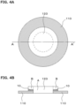
- Fig. 4A is a plan view of the evaluation sample including the resin layer 120, the adhesive laminate 10, and the metal layer 110.
- Fig. 4B is a cross-sectional view of the evaluation sample taken along line A-A' illustrated in Fig. 4A .
- the shape of the metal layer 110 is a doughnut shape in which a hole (hole diameter: 20mm ⁇ ) is formed in the center portion of a disk-shaped member (outer diameter: 50mm ⁇ , thickness: 1 mm).
- the planar shape and cross-sectional shape of the resin layer 120 are a circular shape (see Fig. 4A ) and a substantially T-shape (see Fig. 4B ), respectively.
- the cross-sectional shape of the resin layer 120 includes a columnar portion A having an outer diameter of 20mm ⁇ , and a donut-shaped flange portion B surrounding the upper end of the portion A.
- a portion of the metal layer 110 overlapping the flange portion B is joined by the adhesive laminate 10.
- the above-described adhesive laminate with a release film was cut into a circle having an outer diameter of 30mm ⁇ , and a hole having an inner diameter of 20mm ⁇ was further formed in the center portion of the circle to obtain a donut-shaped adhesive laminate with a release film.
- the release film was separated from the obtained adhesive laminate with a release film to obtain an adhesive laminate.
- the evaluation sample in which the metal layer (metal member) and the molded resin were joined was fabricated using the adhesive laminate described above.
- the adhesive laminate was disposed on the metal layer such that the hole provided in the metal layer would overlap the hole provided in the adhesive laminate.
- the molded resin was molded using a mold having a predetermined shape and an injection molding machine. Conditions at the time of molding the molded resin are as follows.
- the joinability was evaluated by an airtightness test.
- the details of the airtightness test are described below.
- the molded resin 120 filling the hole portion provided in the metal layer 110 was air-pressurized at pressures of 50 kPa, 100 kPa, and 200 kPa in water in a state where the lower portion of the evaluation sample was sealed.
- the presence or absence of air bubbles generated from the side surface of the adhesive laminate 10 was checked, and the j oinability was evaluated according to the following criteria.
- the durability of each evaluation sample was evaluated using a temperature cycle test tank. Specifically, holding the evaluation sample at -40°C (holding time: 30 minutes) and at 125°C (holding time: 30 minutes) was defined as 1 cycle, and 1000 cycles were performed. The evaluation sample that had undergone a durability test of 1000 cycles was evaluated by an airtightness test in water in the same manner as the joinability evaluation.
- the criteria for durability evaluation are as follows.
- the comprehensive evaluations of the evaluation samples using the respective adhesive laminates of Examples 1 to 17 were any one of A (excellent), B (good), and C (acceptable).
- the comprehensive evaluations of the evaluation samples using the respective adhesive laminates of Comparative Examples 1 to 5 were all D (unacceptable).
Landscapes
- Engineering & Computer Science (AREA)
- Mechanical Engineering (AREA)
- Chemical & Material Sciences (AREA)
- Organic Chemistry (AREA)
- Manufacturing & Machinery (AREA)
- Textile Engineering (AREA)
- Laminated Bodies (AREA)
Abstract
Description
- The present invention relates to an adhesive laminate and an electronic device housing.
- As an in-vehicle electronic device housing, a molded article is used in which a metal material (insert material) and a resin (hereinafter, sometimes referred to as "molded resin") are integrated. As a method for integrating a metal material and a resin, an adhesive or an adhesive sheet on a joining surface between the metal material and the resin is used for joining or adhesion.
- For example,
Patent Literature 1 discloses an adhesive sheet including an adhesive containing an epoxy-based resin, an acrylic resin, and a curing agent, and an adhesive layer in which a core material (woven fabric or nonwoven fabric) is impregnated with the adhesive. - Patent Literature 1:
JP 2014-70221 A - In a case where an adhesive is used for integration of a metal material and a resin, there are production-related problems that it is difficult to adjust the application thickness of the adhesive, the adhesive becomes fluid to flow out due to heat and injection pressure during resin molding, and a solvent removal process is required.
- On the other hand, in a case where an adhesive sheet in which a core material such as a nonwoven fabric is impregnated with an adhesive is used, there are problems related to strength characteristics that the nonwoven fabric and the adhesive are easily separated, and when a resin is joined, the resin and the nonwoven fabric are easily separated.
- The present invention has been made in view of the above-described problems, and an object of the present invention is to provide a technique that makes it possible to improve the joining strength between a metal material and a resin while facilitating a process of integrating the metal material and the resin.
- One aspect of the present invention is an adhesive laminate. The adhesive laminate includes: a base material layer including a nonwoven fabric; and an adhesive layer laminated on one main surface of the base material layer and including an adhesive having a glass transition temperature Tg of -40°C or more and 20°C or less, in which an adhesive-impregnated layer impregnated with the adhesive is formed in a part of the base material layer on a side adjacent to the adhesive layer, the base material layer has a thickness of 10 to 100 µm, a portion not impregnated with the adhesive in the base material layer has a thickness of 5 to 50 µm, the adhesive-impregnated layer in the base material layer has a thickness of 5 to 95 µm, and the adhesive layer has a thickness of 5 to 60 µm.
- In the adhesive laminate of the above-described aspect, the adhesive may contain at least one selected from the group consisting of rubber, a thermosetting resin, and a thermoplastic resin. The adhesive may have a viscosity at 150°C of 0.8 × 10³ Pa s or more.
- The nonwoven fabric may be formed of at least one selected from the group consisting of polyphenylene sulfide fibers, polyethylene terephthalate fibers, polyamide fibers, and polybutylene terephthalate fibers.
- In a cross section of the base material layer, an area percentage occupied by the nonwoven fabric may be 5 to 50%. The nonwoven fabric may have a basis weight of 15 to 120 g/m2.
- Another aspect of the present invention is an electronic device housing. In the electronic device housing, a metal layer and a resin layer are joined with the adhesive laminate according to any one of the aspects described above interposed between the metal layer and the resin layer, the metal layer and the resin layer are joined with the adhesive laminate interposed between the metal layer and the resin layer such that the metal layer is in contact with the adhesive layer, and the resin layer including a resin is in contact with the base material layer on a side opposite to a side on which the adhesive layer is laminated, a resin-impregnated layer impregnated with the resin is formed in a part of the base material layer on the side in contact with the resin layer, and the resin-impregnated layer and the adhesive-impregnated layer are in contact with each other in the base material layer.
- According to the present invention, it is possible to improve the joining strength between a metal material and a resin while facilitating a process of integrating the metal material and the resin.
-
-
Fig. 1 is a schematic cross-sectional view illustrating the configuration of an adhesive laminate according to an embodiment. -
Fig. 2 is a schematic cross-sectional view illustrating the configuration of an electronic device housing according to an embodiment. -
Figs. 3A to 3D are process cross-sectional views illustrating a method for producing the electronic device housing. -
Fig. 4A is a plan view of an evaluation sample including aresin layer 120, anadhesive laminate 10, and ametal layer 110.Fig. 4B is a cross-sectional view of the evaluation sample taken along line A-A' illustrated inFig. 4A . -
Fig. 5 is a drawing illustrating the outline of an airtightness test performed in joinability evaluation or durability evaluation. - Hereinafter, embodiments of the present invention will be described in detail. In the present specification, the notation "a to b" in the description of a numerical range represents a or more and b or less unless otherwise specified.
- The configuration of an adhesive laminate according to an embodiment will be described with reference to the drawings.
-
Fig. 1 is a schematic cross-sectional view illustrating the configuration of anadhesive laminate 10 according to the embodiment. As illustrated inFig. 1 , theadhesive laminate 10 includes anadhesive layer 20 and abase material layer 30. - The
adhesive layer 20 is laminated on one main surface of thebase material layer 30 described later. Theadhesive layer 20 contains an adhesive having a glass transition temperature Tg of -40°C or more and 20°C or less. When the Tg of the adhesive is -40°C or more and 20°C or less, the flexibility at a low temperature can be secured. This produces the effect of easily maintaining the adhesive strength even when a thermal stress such as a heat cycle is applied. - Examples of the adhesive described above include at least one selected from the group consisting of rubber, a thermosetting resin, and a thermoplastic resin.
- Examples of the rubber include nitrile rubber (NBR), hydrogenated nitrile rubber (HNBR), acrylic rubber (ACM), and fluoro-rubber (FKM).
- Examples of the thermosetting resin include epoxy resins, maleimide resins, and resol phenol resins.
- Examples of the thermoplastic resin include novolac phenol resins, rosin ester resins, and terpene phenol resins.
- The components of the adhesive can be changed according to the application and the type of an adhesion object. For example, in a case where airtightness or water tightness is required as necessary characteristics, it is preferable to combine the rubber and the thermoplastic resin. In addition, in a case where oil resistance is required as necessary characteristics, it is preferable to combine the rubber and the thermosetting resin, or to use the fluoro-rubber (FKM).
- Note that the adhesive may contain a filler or an additive as another component. Examples of the other component include inorganic fillers, flame retardants, conductivity imparting agents, crystal nucleating agents, ultraviolet absorbers, antioxidants, vibration damping agents, antibacterial agents, insect repellents, deodorants, coloring inhibitors, heat stabilizers, antistatic agents, plasticizers, lubricants, coloring agents, foaming agents, foam inhibitors, coupling agents, tackifier resins such as tackifiers, and curing agents.
- The lower limit of the viscosity of the adhesive at 150°C is 0.8 × 10³ Pa s or more, and preferably 1 × 10³ Pa·s, 5 × 10³ Pa·s, or 1 × 10⁴ Pa·s or more. By setting the above lower limit of the viscosity to 0.8 × 10³ Pa·s or more, it is possible to inhibit separation of the
adhesive layer 20 due to heat and pressure received at the time of injection molding of a molded resin. In addition, when the adhesive described above enters voids of a nonwoven fabric forming thebase material layer 30 described later, it is possible to inhibit introduction of voids into the adhesive, and eventually, it is possible to improve the airtightness. - The upper limit of the viscosity of the adhesive at 150°C is not particularly limited, but for example, is preferably 5 × 10⁵ Pa·s or less, and more preferably 5 × 10⁴ Pa s or less.
- The thickness of the
adhesive layer 20 is 5 to 60 µm, and preferably 10 to 55 µm, or 15 to 50 µm. - By setting the lower limit of the thickness of the
adhesive layer 20 to the above value, theadhesive layer 20 becomes easy to follow deformation in a heat cycle of about -40°C to 130°C, making it possible to sufficiently maintain the airtightness. On the other hand, by setting the upper limit of the thickness of theadhesive layer 20 to the above value, it is possible to inhibit the adhesive from flowing out under a pressure at the time of injecting the molded resin even when the adhesive having a Tg of -40°C or more and 20°C or less is used. - The
base material layer 30 contains a nonwoven fabric. The nonwoven fabric is formed of at least one selected from the group consisting of polyphenylene sulfide (PPS) fibers, polyethylene terephthalate (PET) fibers, polyamide (PA) fibers, and polybutylene terephthalate (PBT) fibers, for example. - As the nonwoven fabric used for the
base material layer 30, it is preferable to select a nonwoven fabric that is compatible with the molded resin. For example, in a case where PPS is used as the molded resin, it is preferable to use PPS fibers for the nonwoven fabric. In a case where PBT is used as the molded resin, it is preferable to use PBT fibers or PET fibers for the nonwoven fabric. In addition, in a case where PA is used for the molded resin, it is preferable to use PA fibers or PPS fibers for the nonwoven fabric. - In the cross section of the
base material layer 30, an area percentage occupied by the nonwoven fabric is preferably 5 to 50%, more preferably 20 to 45%, and still more preferably 30 to 40%. By setting the area percentage within the above range, it is possible to obtain a sufficient anchor effect between the molded resin and the nonwoven fabric, which is caused by the molded resin entering the nonwoven fabric by injection molding, while inhibiting generation of voids in the base material layer. - The basis weight of the nonwoven fabric is preferably 15 to 120 g/m2, more preferably 20 to 110 g/m2, and still more preferably 30 to 100 g/m2.
- The tensile strength of the nonwoven fabric in the MD direction measured in accordance with JIS-P8113 is preferably 0.2 kN/m to 8.0 kN/m, more preferably 0.4 kN/m to 7.0 kN/m, and still more preferably 0.6 kN/m to 6.0 kN/m. In addition, the tensile strength of the nonwoven fabric in the CD direction measured in accordance with JIS-P8113 is preferably 0.05 kN/m to 4.0 kN/m, more preferably 0.10 kN/m to 3.0 kN/m, and still more preferably 0.15 kN/m to 2.0 kN/m.
- By setting the tensile strength of the nonwoven fabric in the MD direction (flow direction during production of the nonwoven fabric, longitudinal direction of the adhesive laminate 10) and the CD direction (direction orthogonal to the MD direction) within the above ranges, the mechanical strength of the
base material layer 30 can be enhanced, and eventually the durability of theadhesive laminate 10 can be enhanced. - In the
base material layer 30, an adhesive-impregnatedlayer 32 impregnated with the adhesive described above is formed in a part of thebase material layer 30 on the side adjacent to theadhesive layer 20. - The thickness of the
base material layer 30 is 10 to 100 µm, and preferably 20 to 90 µm or 30 to 80 µm. - In the
base material layer 30, the thickness of the adhesive-impregnatedlayer 32 is 5 to 95 µm, and preferably 10 to 90 µm or 15 to 85 µm. - In the
base material layer 30, the thickness of a portion not impregnated with the adhesive (region denoted byreference numeral 34 inFig. 1 ) is 5 to 50 µm, and preferably 10 to 45 µm or 15 to 40 µm. - By setting the thickness of the
base material layer 30 and the thicknesses of the adhesive-impregnatedlayer 32 and the portion not impregnated with the adhesive within the above ranges, the joining strength and airtightness between a metal material and the molded resin can be improved. - More specifically, by setting the lower limit of the thickness of the adhesive-impregnated
layer 32 to the above value, it is possible to inhibit separation between the adhesive and the nonwoven fabric at the time of injection molding of the molded resin. On the other hand, by setting the upper limit of the thickness of the adhesive-impregnatedlayer 32 to the above value, a sufficient thickness can be secured for the portion not impregnated with the adhesive (portion of only the nonwoven fabric), and a sufficient anchor effect between the molded resin and the nonwoven fabric can be obtained. - By setting the lower limit of the thickness of the portion not impregnated with the adhesive (portion of only the nonwoven fabric) to the above value, a sufficient anchor effect between the molded resin and the nonwoven fabric can be obtained, and eventually the occurrence of separation between the molded resin and the nonwoven fabric can be inhibited. On the other hand, by setting the upper limit of the thickness of the portion not impregnated with the adhesive (portion of only the nonwoven fabric) to the above value, the molded resin can sufficiently enter the inside of the nonwoven fabric at the time of injection molding of the molded resin, and it is possible to inhibit generation of voids in the
base material layer 30, and eventually to improve the airtightness. - The nonwoven fabric constituting the
base material layer 30 preferably exhibits hydrophilicity, and for example, this nonwoven fabric preferably has a contact angle of 90 degrees or less. - The
adhesive laminate 10 described above has at least the following effects in addition to the effects described above. - Since resin molding can be performed in a state where the adhesive laminate is stuck to the metal material (insert material), the resin molding can be easily incorporated into a production process, and a process of integrating the metal material and the molded resin can be facilitated.
- Since the adhesive is held in the nonwoven fabric, even when the adhesive having a Tg of -40°C or more and 20°C or less is used, not only the adhesive is inhibited from becoming fluid at a high temperature, but also a sufficient adhesive holding force is secured against a thermal stress due to slow cooling after molding of the molded resin. Therefore, the separation of the adhesive is inhibited.
- Since the
adhesive laminate 10 according to the embodiment has a sheet shape in a solid state at normal temperature, there is no concern about a change in solid content due to volatilization of a solvent during storage, an increase in coating material viscosity, and the like as compared with a solvent-containing type liquid adhesive. Therefore, theadhesive laminate 10 is excellent in storage stability. - As a method for producing the
adhesive laminate 10 according to the embodiment, a sheet with an adhesive layer is fabricated by applying a predetermined application amount of solvent-containing adhesive to a release film of PET or the like and removing the solvent by a ventilation oven or the like. A process of applying a temperature of 80 to 200°C in a state where thebase material layer 30 is laminated on the obtained sheet with a pressure-sensitive adhesive layer (pressure-sensitive adhesive layer with a release film) to impregnate a part of thebase material layer 30 with the melted adhesive is performed. As a result, the adhesive-impregnatedlayer 32 having a predetermined thickness is formed in a part of thebase material layer 30. The thickness of the adhesive-impregnatedlayer 32 can be set to a desired value by adjusting the amount of application of the adhesive, the applied temperature, and the pressure at the time of lamination. -
Fig. 2 is a schematic cross-sectional view illustrating the configuration of anelectronic device housing 100 according to an embodiment. - The
electronic device housing 100 according to the embodiment has a structure in which ametal layer 110 and aresin layer 120 are joined with theadhesive laminate 10 described above interposed therebetween. - The
metal layer 110 and theresin layer 120 are joined with theadhesive laminate 10 interposed therebetween such that themetal layer 110 is in contact with theadhesive layer 20 described above, and theresin layer 120 containing a resin is in contact with thebase material layer 30 on the side opposite to the side on which theadhesive layer 20 is laminated. - A resin-impregnated
layer 36 impregnated with the resin is formed in a part of thebase material layer 30 on the side in contact with theresin layer 120. The resin-impregnatedlayer 36 and the adhesive-impregnatedlayer 32 are in contact with each other in thebase material layer 30. - Specific examples of the electronic device housing include electronic components such as a busbar and a terminal. These electronic components may be used to be mounted on automobiles, used for precision components, or the like. Since the electronic device housing of the present embodiment is excellent in adhesive strength and airtightness/water tightness, the electronic device housing is suitably mounted on automobiles which demand high levels of these characteristics.
-
Figs. 3A to 3D are process cross-sectional views illustrating a method for producing the electronic device housing. - As illustrated in
Fig. 3A , themetal layer 110 is set in a mold (not illustrated). Examples of the material of themetal layer 110 include SUS, aluminum, copper, and plated (for example, nickel-plated, tin-plated) metal materials. On the other hand, theadhesive laminate 10 in which arelease film 40 is laminated on theadhesive layer 20 is prepared. Examples of the material of therelease film 40 include polystyrene terephthalate (PET). - Next, as illustrated in
Fig. 3B , therelease film 40 is removed, and theadhesive laminate 10 is stuck to themetal layer 110. In a case where a thermosetting resin is used as the adhesive for theadhesive layer 20, theadhesive laminate 10 is stuck to themetal layer 110 and then heated to cure the adhesive, so that themetal layer 110 and theadhesive layer 20 can firmly adhere to each other, and heat resistance can be imparted. - Next, as illustrated in
Fig. 3C , the molded resin is injection-molded into a space where theadhesive laminate 10 is stuck to themetal layer 110. At this time, the melted molded resin flows into thebase material layer 30, and the melted adhesive flows into thebase material layer 30, so that the molded resin and the adhesive come into contact with each other. As a result, the anchor effect is exerted between the molded resin and the nonwoven fabric, and themetal layer 110 and theresin layer 120 are firmly joined together. Examples of the molded resin include engineering plastics such as PPS, PBT, and PA, or super engineering plastics. - Next, as illustrated in
Fig. 3D , demolding is performed after completion of the injection molding, whereby theelectronic device housing 100 can be obtained. - Molding conditions vary depending on the type of the molded resin and the like. For example, the molded resin can be molded under the conditions of a mold temperature of 40 to 160°C, a cylinder temperature of 200 to 400°C, an injection pressure of 20 to 120 MPa, a holding pressure of 20 to 120 MPa, an injection speed of 10 to 120 mm/sec, and the like.
- Although the embodiments of the present invention have been described above, these are examples of the present invention, and various configurations other than the above can be adopted.
- Hereinafter, the present invention will be described using Examples and Comparative Examples, but the present invention is not limited to them.
- According to the respective components and the corresponding blending amounts listed in Table 1, adhesives of
blends 1 to 9 were prepared. - 100 g of the adhesive of blend 4 was diluted and mixed with 400 g of a methyl ethyl ketone solvent to obtain a mixed solution. The mixed solution was applied onto a release PET film so as to have a thickness of 48 µm, and then subjected to a drying treatment (100°C/5 minutes) in a ventilation oven to fabricate an adhesive layer with a release film. Furthermore, the above adhesive layer with a release film and a nonwoven fabric (thickness: 50 µm, made of polyphenylene sulfide (PPS)) were thermally stuck to each other at 150°C such that the surface of the adhesive layer on the side to which the release film was not stuck and the above nonwoven fabric would come into contact with each other to fabricate an adhesive laminate with a release film. The adhesive laminate used at the time of each evaluation described later is in a state in which the release film has been separated.
- Adhesive laminates of Examples 2 to 17 and Comparative Examples 1 to 5 were fabricated by the same fabrication method as in Example 1 except that the blends, the thickness of the base material layer (thickness of each of the adhesive-impregnated layer and the adhesive-non-impregnated layer), and the thickness of the adhesive layer were adjusted as listed in Table 2.
[Table 1] Blend 1Blend 2 Blend 3Blend 4 Blend 5 Blend 6 Blend 7 Blend 8 Blend 9 Bis A Liquid Epoxy Resin (Molecular Weight: 370, Epoxy Equivalent: 190) Mass Part(s) 20 10 60 5 Polyfunctional Epoxy Resin (Molecular Weight: 392, Tetrafunction, Epoxy Equivalent: 98) 20 Tackifier = Terpene Phenol Resin (Softening Point: 160°C) 10 5 20 Acrylic Rubber (Tg = 10°C, Mw = 900,000) 100 100 100 Acrylic Rubber (Tg = 10°C, Mw = 900,000, Containing Carboxyl Group) 100 Acrylic Rubber (Tg = -40°C, Mw = 1,200,000) 100 100 100 100 100 Curing Agent (2-Methyl-4-Methylimidazole) 5 5 5 5 1 Plasticizer (Liquid Acrylic Polymer, Tg = -60°C, Mw = 3,000) 40 

- An electron micrograph of the cross section of the adhesive laminate was taken at a magnification of 1000 times.
- Lines were drawn at a position where the thickness of the adhesive-impregnated layer was the thickest and a position where the thickness of the adhesive-impregnated layer was the thinnest in the extending direction of the adhesive laminate, respectively, and an intermediate line of these two lines was defined as a boundary between the adhesive-impregnated layer and the adhesive-non-impregnated layer.
- In addition, lines were drawn at the most protruding position and the most recessed position in one main surface of the base material layer, respectively, and an intermediate line of these two lines was defined as a reference line of the one main surface of the base material layer.
- Similarly, lines were drawn at the most protruding position and the most recessed position in the other main surface of the base material layer, respectively, and an intermediate line of these two lines was defined as a reference line of the other main surface of the base material layer.
- A difference between one reference line of the base material layer and the other reference line of the base material layer was defined as the thickness of the base material layer. In addition, a difference between the boundary between the adhesive-impregnated layer and the adhesive-non-impregnated layer, and the other reference line (reference line on the adhesive layer side) of the base material layer was defined as the thickness of the adhesive-impregnated layer. In addition, a difference between the thickness of the base material layer and the thickness of the adhesive-impregnated layer was defined as the thickness of the adhesive-non-impregnated layer.
- A measurement sample was obtained by collecting the adhesive of the adhesive layer from the adhesive laminate, and adjusting only the adhesive to a thickness of 1 mm. Shear viscosity measurement was performed using a rheometer (HAAKE MARS iQ manufactured by Thermo Fisher Scientific K.K.). Conditions for the shear viscosity measurement are as follows.
- Evaluation probe: 20 mmϕ parallel plate
- Measurement load: 15 N
- Measurement frequency: 1 Hz
- Temperature condition: temperature increase from 25°C to 150°C at 10°C/min (viscosity when the temperature reaches 150°C is defined as viscosity at 150°C)
- The cross section of the adhesive laminate was cut out, and the cross section of the base material layer was observed at a magnification of 1000 times using an optical microscope (digital microscope VHX-500 manufactured by KEYENCE CORPORATION). Specifically, the obtained image was subjected to a binarization treatment to distinguish a fibrous material from other materials, and then the area percentage (%) of the fibrous material present per unit area was obtained.
- The adhesive was removed from the nonwoven fabric using an adhesive-solubilizing solvent (methyl ethyl ketone), the above adhesive-solubilizing solvent was dried, then the nonwoven fabric was cut into 200 mm × 250 mm, and the weight was measured using an electronic balance. The basis weight (g/m2) was calculated according to the following formula.

- The adhesive was removed from the nonwoven fabric using an adhesive-solubilizing solvent (methyl ethyl ketone), the above adhesive-solubilizing solvent was dried, and then the thickness of the nonwoven fabric was measured in accordance with JIS P8118 (2014). The density of the nonwoven fabric was calculated from the following formula using the value of the basis weight measured by the above method.
- The density was calculated from the basis weight/thickness = (g/cm3).
- The adhesive laminate (test piece) was prepared by cutting the nonwoven fabric to have a width of 15 mm in each of the MD direction and the CD direction. The tensile strength of this sample was measured by a universal tension testing machine. Measurement conditions in the tensile strength measurement are as follows.
- Temperature: 25°C
- Tensile speed: 20 mm/min
- Test length: Adjust a gripper position such that the test length becomes 180 mm
- The tensile strength measurement was started under the above measurement conditions, and continued until the test piece was broken. Using a maximum strength F [kN] and a measurement width W [m] obtained at this time, the tensile strength [kN/m] was calculated according to the following formula.

- The configuration of an evaluation sample used for the evaluation of each of joinability and durability will be described.
-
Fig. 4A is a plan view of the evaluation sample including theresin layer 120, theadhesive laminate 10, and themetal layer 110.Fig. 4B is a cross-sectional view of the evaluation sample taken along line A-A' illustrated inFig. 4A . - The shape of the
metal layer 110 is a doughnut shape in which a hole (hole diameter: 20mmΦ) is formed in the center portion of a disk-shaped member (outer diameter: 50mmΦ, thickness: 1 mm). - The planar shape and cross-sectional shape of the
resin layer 120 are a circular shape (seeFig. 4A ) and a substantially T-shape (seeFig. 4B ), respectively. - More specifically, the cross-sectional shape of the
resin layer 120 includes a columnar portion A having an outer diameter of 20mmΦ, and a donut-shaped flange portion B surrounding the upper end of the portion A. A portion of themetal layer 110 overlapping the flange portion B is joined by theadhesive laminate 10. - A method for fabricating the evaluation sample used for the evaluation of each of j oinability and durability will be described.
- The above-described adhesive laminate with a release film was cut into a circle having an outer diameter of 30mmΦ, and a hole having an inner diameter of 20mmΦ was further formed in the center portion of the circle to obtain a donut-shaped adhesive laminate with a release film. The release film was separated from the obtained adhesive laminate with a release film to obtain an adhesive laminate.
- The evaluation sample in which the metal layer (metal member) and the molded resin were joined was fabricated using the adhesive laminate described above.
- Specifically, the adhesive laminate was disposed on the metal layer such that the hole provided in the metal layer would overlap the hole provided in the adhesive laminate. In this state, the molded resin was molded using a mold having a predetermined shape and an injection molding machine. Conditions at the time of molding the molded resin are as follows.
- Metal member: A5052 material (aluminum alloy)
- Molded resin: PPS-GF30 manufactured by KINGFA SCI. & TECH. Co., Ltd.
- Mold temperature: 150°C
- Cylinder temperature: 310°C
- Holding pressure: 60 MPa
- Injection speed: 60 mm/min
- For each evaluation sample, the joinability was evaluated by an airtightness test. The details of the airtightness test are described below. As illustrated in
Fig. 5 , the moldedresin 120 filling the hole portion provided in themetal layer 110 was air-pressurized at pressures of 50 kPa, 100 kPa, and 200 kPa in water in a state where the lower portion of the evaluation sample was sealed. As illustrated inFig. 5 , the presence or absence of air bubbles generated from the side surface of theadhesive laminate 10 was checked, and the j oinability was evaluated according to the following criteria. - A (excellent): No air bubbles are generated during air pressurization of 50 kPa, 100 kPa, and 200 kPa.
- B (good): Leakage occurs during air pressurization of 200 kPa, and no air bubbles are generated during air pressurization of 50 kPa and 100 kPa.
- C (acceptable): Leakage occurs during air pressurization of 100 kPa and 200 kPa, and no air bubbles are generated during air pressurization of 50 kPa.
- D (unacceptable): Separation occurs after molding (after demolding).
- The durability of each evaluation sample was evaluated using a temperature cycle test tank. Specifically, holding the evaluation sample at -40°C (holding time: 30 minutes) and at 125°C (holding time: 30 minutes) was defined as 1 cycle, and 1000 cycles were performed. The evaluation sample that had undergone a durability test of 1000 cycles was evaluated by an airtightness test in water in the same manner as the joinability evaluation. The criteria for durability evaluation are as follows.
- A (excellent): No air bubbles are generated during air pressurization of 50 kPa, 100 kPa, and 200 kPa.
- B (good): Leakage occurs during air pressurization of 200 kPa, and no air bubbles are generated during air pressurization of 50 kPa and 100 kPa.
- C (acceptable): Leakage occurs during air pressurization of 100 kPa and 200 kPa, and no air bubbles are generated during air pressurization of 50 kPa.
- D (unacceptable): Separation occurs after a durability test of 1000 cycles.
- The comprehensive evaluation of each evaluation sample was determined according to the following criteria.
- A (excellent): Both joinability and durability are A
- B (good): One of joinability and durability is A, and the other is B
- C (acceptable): One of j oinability and durability is A, B, or C and the other is C
- D (unacceptable): One of joinability and durability is A, B, C, or D, and the other is D.
- As listed in Table 2, the comprehensive evaluations of the evaluation samples using the respective adhesive laminates of Examples 1 to 17 were any one of A (excellent), B (good), and C (acceptable). On the other hand, the comprehensive evaluations of the evaluation samples using the respective adhesive laminates of Comparative Examples 1 to 5 were all D (unacceptable).
-
- 10
- Adhesive laminate
- 20
- Adhesive layer
- 30
- Base material layer
- 32
- Adhesive-impregnated layer
- 34
- Portion not impregnated with an adhesive
- 36
- Resin-impregnated layer
- 40
- Release film
- 100
- Electronic device housing
- 110
- Metal layer
- 120
- Resin layer
Claims (7)
- An adhesive laminate comprising:a base material layer including a nonwoven fabric; andan adhesive layer laminated on one main surface of the base material layer and including an adhesive having a glass transition temperature Tg of -40°C or more and 20°C or less, whereinan adhesive-impregnated layer impregnated with the adhesive is formed in a part of the base material layer on a side adjacent to the adhesive layer,the base material layer has a thickness of 10 to 100 µm,a portion not impregnated with the adhesive in the base material layer has a thickness of 5 to 50 µm,the adhesive-impregnated layer in the base material layer has a thickness of 5 to 95 µm, andthe adhesive layer has a thickness of 5 to 60 µm.
- The adhesive laminate according to claim 1, wherein the adhesive contains at least one selected from the group consisting of rubber, a thermosetting resin, and a thermoplastic resin.
- The adhesive laminate according to claim 1 or 2, wherein the adhesive has a viscosity at 150°C of 0.8 × 10³ Pa·s or more.
- The adhesive laminate according to any one of claims 1 to 3, wherein the nonwoven fabric is formed of at least one selected from the group consisting of polyphenylene sulfide fibers, polyethylene terephthalate fibers, polyamide fibers, and polybutylene terephthalate fibers.
- The adhesive laminate according to any one of claims 1 to 4, wherein in a cross section of the base material layer, an area percentage occupied by the nonwoven fabric is 5 to 50%.
- The adhesive laminate according to any one of claims 1 to 5, wherein the nonwoven fabric has a basis weight of 15 to 120 g/m2.
- An electronic device housing, whereina metal layer and a resin layer are joined with the adhesive laminate according to any one of claims 1 to 6 interposed between the metal layer and the resin layer,the metal layer and the resin layer are joined with the adhesive laminate interposed between the metal layer and the resin layer such that the metal layer is in contact with the adhesive layer, and the resin layer including a resin is in contact with the base material layer on a side opposite to a side on which the adhesive layer is laminated,a resin-impregnated layer impregnated with the resin is formed in a part of the base material layer on the side in contact with the resin layer, andthe resin-impregnated layer and the adhesive-impregnated layer are in contact with each other in the base material layer.
Applications Claiming Priority (2)
| Application Number | Priority Date | Filing Date | Title |
|---|---|---|---|
| JP2022018189 | 2022-02-08 | ||
| PCT/JP2023/004038 WO2023153409A1 (en) | 2022-02-08 | 2023-02-07 | Bonded laminate and electronic device housing |
Publications (2)
| Publication Number | Publication Date |
|---|---|
| EP4477392A1 true EP4477392A1 (en) | 2024-12-18 |
| EP4477392A4 EP4477392A4 (en) | 2026-03-04 |
Family
ID=87564439
Family Applications (1)
| Application Number | Title | Priority Date | Filing Date |
|---|---|---|---|
| EP23752873.2A Pending EP4477392A4 (en) | 2022-02-08 | 2023-02-07 | Bonded laminate and electronic device housing |
Country Status (7)
| Country | Link |
|---|---|
| US (1) | US20250129270A1 (en) |
| EP (1) | EP4477392A4 (en) |
| JP (1) | JPWO2023153409A1 (en) |
| KR (1) | KR20240141323A (en) |
| CN (1) | CN118660807A (en) |
| TW (1) | TW202342283A (en) |
| WO (1) | WO2023153409A1 (en) |
Families Citing this family (2)
| Publication number | Priority date | Publication date | Assignee | Title |
|---|---|---|---|---|
| TW202528122A (en) * | 2023-09-22 | 2025-07-16 | 美商科慕Fc有限責任公司 | Composites including incompatible polymers and/or other incompatible materials |
| WO2026048277A1 (en) * | 2024-08-29 | 2026-03-05 | パナソニックIpマネジメント株式会社 | Coated molded article and method for producing the same |
Family Cites Families (14)
| Publication number | Priority date | Publication date | Assignee | Title |
|---|---|---|---|---|
| US3965022A (en) * | 1973-06-29 | 1976-06-22 | Minnesota Mining And Manufacturing Company | Pressure-fixable developing powder |
| EP0430301A2 (en) * | 1989-12-01 | 1991-06-05 | Avery Dennison Corporation | Olefin polymer based pressure-sensitive adhesives |
| JPH0649422A (en) * | 1992-07-29 | 1994-02-22 | Sekisui Chem Co Ltd | Tacky tape and its production |
| JPH06306336A (en) * | 1993-04-22 | 1994-11-01 | Sekisui Chem Co Ltd | Double-sided adhesive tape manufacturing method |
| JP2001200218A (en) * | 2000-01-14 | 2001-07-24 | Hitachi Kasei Polymer Co Ltd | Water releasable double-coated tape |
| JP4579498B2 (en) * | 2003-02-03 | 2010-11-10 | リンテック株式会社 | Adhesive sheet |
| AU2003213401A1 (en) * | 2003-03-17 | 2004-10-11 | Idemitsu Unitech Co., Ltd. | Heat-bondable sheet and packaging material |
| JP4984603B2 (en) * | 2006-03-31 | 2012-07-25 | Dic株式会社 | Manufacturing method of adhesive tape |
| US9061478B2 (en) * | 2011-05-18 | 2015-06-23 | 3M Innovative Properties Company | Conductive nonwoven pressure sensitive adhesive tapes and articles therefrom |
| JP6044243B2 (en) | 2012-10-02 | 2016-12-14 | 大日本印刷株式会社 | Adhesive composition and adhesive sheet using it |
| KR101411589B1 (en) | 2012-11-30 | 2014-06-25 | 삼성중공업 주식회사 | Floor heating device of ship |
| JP6303849B2 (en) * | 2014-06-16 | 2018-04-04 | 東レ株式会社 | FIBER-REINFORCED RESIN SHEET, INTEGRATED MOLDED ARTICLE AND METHOD FOR PRODUCING THEM |
| TWI768213B (en) * | 2018-11-08 | 2022-06-21 | 日商拓自達電線股份有限公司 | Electromagnetic wave shielding film, method for producing electromagnetic wave shielding film, and method for producing shielded printed wiring board |
| JP7320360B2 (en) * | 2019-03-06 | 2023-08-03 | 日東電工株式会社 | Adhesive sheet |
-
2023
- 2023-02-07 US US18/836,372 patent/US20250129270A1/en active Pending
- 2023-02-07 EP EP23752873.2A patent/EP4477392A4/en active Pending
- 2023-02-07 TW TW112104292A patent/TW202342283A/en unknown
- 2023-02-07 KR KR1020247029870A patent/KR20240141323A/en active Pending
- 2023-02-07 CN CN202380020486.2A patent/CN118660807A/en active Pending
- 2023-02-07 JP JP2023580272A patent/JPWO2023153409A1/ja active Pending
- 2023-02-07 WO PCT/JP2023/004038 patent/WO2023153409A1/en not_active Ceased
Also Published As
| Publication number | Publication date |
|---|---|
| EP4477392A4 (en) | 2026-03-04 |
| JPWO2023153409A1 (en) | 2023-08-17 |
| TW202342283A (en) | 2023-11-01 |
| WO2023153409A1 (en) | 2023-08-17 |
| US20250129270A1 (en) | 2025-04-24 |
| CN118660807A (en) | 2024-09-17 |
| KR20240141323A (en) | 2024-09-26 |
Similar Documents
| Publication | Publication Date | Title |
|---|---|---|
| EP4477392A1 (en) | Bonded laminate and electronic device housing | |
| US8173238B2 (en) | Composite shaped article and process for manufacturing the same | |
| JP4774839B2 (en) | Manufacturing method of fiber reinforced composite material | |
| US20130242487A1 (en) | Method for producing metal composite, and chassis for electronic equipment | |
| JPWO2018142971A1 (en) | Integrated molded body and manufacturing method thereof | |
| KR20090073081A (en) | Process for producing composite prepreg base, layered base, and fiber-reinforced plastic | |
| EP4249541B1 (en) | Fiber-reinforced resin substrate, preform, integrated molded article, and method for producing fiber-reinforced resin substrate | |
| US12269225B2 (en) | Fiber-reinforced resin substrate, integrated molded article, and method for manufacturing fiber-reinforced resin substrate | |
| JP7847900B2 (en) | Heat-expanded foam sheet and bonding method | |
| JP2020513351A (en) | Plastic composite core member and method of manufacturing the same | |
| US8318067B2 (en) | Resin transfer moulding process for an article containing a protective member | |
| JP2019089297A (en) | Composite member and method for producing the same | |
| KR101999530B1 (en) | Sandwich panel and the manufacturing method for the same | |
| CN114787252A (en) | Prepreg, laminate, and integrated molded article | |
| JP6239533B2 (en) | Method for producing resin molded body and graphite sheet laminate | |
| JP2006192745A (en) | REINFORCED FIBER BASE, PREFORM, FIBER-REINFORCED RESIN MOLDED PRODUCT AND METHOD | |
| KR102763715B1 (en) | Prepregs, moulded bodies and integral moulded bodies | |
| JP2020193336A (en) | Molding material and molding | |
| JP2009214371A (en) | Method for manufacturing fiber-reinforced composite material and fiber-reinforced composite material, method for manufacturing integrated structural member and integrated structural member | |
| TWI888690B (en) | Prepreg, molded article and integral molded article | |
| KR20250168453A (en) | Adhesive compositions, adhesive laminates and composite members | |
| JP7656710B2 (en) | Manufacturing method of molded product | |
| KR102707306B1 (en) | Magnetic components having elastic magnetic compounds | |
| KR20060051518A (en) | Fuel Cell Components | |
| WO2025159040A1 (en) | Thermoplastic adhesive sheet, method for using same, and adhesive structure |
Legal Events
| Date | Code | Title | Description |
|---|---|---|---|
| STAA | Information on the status of an ep patent application or granted ep patent |
Free format text: STATUS: THE INTERNATIONAL PUBLICATION HAS BEEN MADE |
|
| PUAI | Public reference made under article 153(3) epc to a published international application that has entered the european phase |
Free format text: ORIGINAL CODE: 0009012 |
|
| STAA | Information on the status of an ep patent application or granted ep patent |
Free format text: STATUS: REQUEST FOR EXAMINATION WAS MADE |
|
| 17P | Request for examination filed |
Effective date: 20240822 |
|
| AK | Designated contracting states |
Kind code of ref document: A1 Designated state(s): AL AT BE BG CH CY CZ DE DK EE ES FI FR GB GR HR HU IE IS IT LI LT LU LV MC ME MK MT NL NO PL PT RO RS SE SI SK SM TR |
|
| DAV | Request for validation of the european patent (deleted) | ||
| DAX | Request for extension of the european patent (deleted) | ||
| A4 | Supplementary search report drawn up and despatched |
Effective date: 20260203 |
|
| RIC1 | Information provided on ipc code assigned before grant |
Ipc: B29C 65/50 20060101AFI20260128BHEP Ipc: B29C 45/14 20060101ALI20260128BHEP Ipc: B29C 65/70 20060101ALI20260128BHEP Ipc: C09J 7/21 20180101ALI20260128BHEP Ipc: C09J 201/00 20060101ALI20260128BHEP |