EP4477388A1 - Additive manufacturing method and device for complex structure of fiber reinforced composite material - Google Patents
Additive manufacturing method and device for complex structure of fiber reinforced composite material Download PDFInfo
- Publication number
- EP4477388A1 EP4477388A1 EP23844060.6A EP23844060A EP4477388A1 EP 4477388 A1 EP4477388 A1 EP 4477388A1 EP 23844060 A EP23844060 A EP 23844060A EP 4477388 A1 EP4477388 A1 EP 4477388A1
- Authority
- EP
- European Patent Office
- Prior art keywords
- fiber
- printing
- composite material
- honeycomb
- additive manufacturing
- Prior art date
- Legal status (The legal status is an assumption and is not a legal conclusion. Google has not performed a legal analysis and makes no representation as to the accuracy of the status listed.)
- Pending
Links
Images






Classifications
-
- B—PERFORMING OPERATIONS; TRANSPORTING
- B29—WORKING OF PLASTICS; WORKING OF SUBSTANCES IN A PLASTIC STATE IN GENERAL
- B29C—SHAPING OR JOINING OF PLASTICS; SHAPING OF MATERIAL IN A PLASTIC STATE, NOT OTHERWISE PROVIDED FOR; AFTER-TREATMENT OF THE SHAPED PRODUCTS, e.g. REPAIRING
- B29C64/00—Additive manufacturing, i.e. manufacturing of three-dimensional [3D] objects by additive deposition, additive agglomeration or additive layering, e.g. by 3D printing, stereolithography or selective laser sintering
- B29C64/10—Processes of additive manufacturing
- B29C64/165—Processes of additive manufacturing using a combination of solid and fluid materials, e.g. a powder selectively bound by a liquid binder, catalyst, inhibitor or energy absorber
-
- B—PERFORMING OPERATIONS; TRANSPORTING
- B29—WORKING OF PLASTICS; WORKING OF SUBSTANCES IN A PLASTIC STATE IN GENERAL
- B29C—SHAPING OR JOINING OF PLASTICS; SHAPING OF MATERIAL IN A PLASTIC STATE, NOT OTHERWISE PROVIDED FOR; AFTER-TREATMENT OF THE SHAPED PRODUCTS, e.g. REPAIRING
- B29C64/00—Additive manufacturing, i.e. manufacturing of three-dimensional [3D] objects by additive deposition, additive agglomeration or additive layering, e.g. by 3D printing, stereolithography or selective laser sintering
- B29C64/10—Processes of additive manufacturing
- B29C64/106—Processes of additive manufacturing using only liquids or viscous materials, e.g. depositing a continuous bead of viscous material
- B29C64/118—Processes of additive manufacturing using only liquids or viscous materials, e.g. depositing a continuous bead of viscous material using filamentary material being melted, e.g. fused deposition modelling [FDM]
-
- B—PERFORMING OPERATIONS; TRANSPORTING
- B29—WORKING OF PLASTICS; WORKING OF SUBSTANCES IN A PLASTIC STATE IN GENERAL
- B29C—SHAPING OR JOINING OF PLASTICS; SHAPING OF MATERIAL IN A PLASTIC STATE, NOT OTHERWISE PROVIDED FOR; AFTER-TREATMENT OF THE SHAPED PRODUCTS, e.g. REPAIRING
- B29C64/00—Additive manufacturing, i.e. manufacturing of three-dimensional [3D] objects by additive deposition, additive agglomeration or additive layering, e.g. by 3D printing, stereolithography or selective laser sintering
- B29C64/20—Apparatus for additive manufacturing; Details thereof or accessories therefor
- B29C64/205—Means for applying layers
- B29C64/209—Heads; Nozzles
-
- B—PERFORMING OPERATIONS; TRANSPORTING
- B29—WORKING OF PLASTICS; WORKING OF SUBSTANCES IN A PLASTIC STATE IN GENERAL
- B29C—SHAPING OR JOINING OF PLASTICS; SHAPING OF MATERIAL IN A PLASTIC STATE, NOT OTHERWISE PROVIDED FOR; AFTER-TREATMENT OF THE SHAPED PRODUCTS, e.g. REPAIRING
- B29C64/00—Additive manufacturing, i.e. manufacturing of three-dimensional [3D] objects by additive deposition, additive agglomeration or additive layering, e.g. by 3D printing, stereolithography or selective laser sintering
- B29C64/20—Apparatus for additive manufacturing; Details thereof or accessories therefor
- B29C64/205—Means for applying layers
- B29C64/218—Rollers
-
- B—PERFORMING OPERATIONS; TRANSPORTING
- B29—WORKING OF PLASTICS; WORKING OF SUBSTANCES IN A PLASTIC STATE IN GENERAL
- B29C—SHAPING OR JOINING OF PLASTICS; SHAPING OF MATERIAL IN A PLASTIC STATE, NOT OTHERWISE PROVIDED FOR; AFTER-TREATMENT OF THE SHAPED PRODUCTS, e.g. REPAIRING
- B29C64/00—Additive manufacturing, i.e. manufacturing of three-dimensional [3D] objects by additive deposition, additive agglomeration or additive layering, e.g. by 3D printing, stereolithography or selective laser sintering
- B29C64/30—Auxiliary operations or equipment
- B29C64/386—Data acquisition or data processing for additive manufacturing
- B29C64/393—Data acquisition or data processing for additive manufacturing for controlling or regulating additive manufacturing processes
-
- B—PERFORMING OPERATIONS; TRANSPORTING
- B29—WORKING OF PLASTICS; WORKING OF SUBSTANCES IN A PLASTIC STATE IN GENERAL
- B29C—SHAPING OR JOINING OF PLASTICS; SHAPING OF MATERIAL IN A PLASTIC STATE, NOT OTHERWISE PROVIDED FOR; AFTER-TREATMENT OF THE SHAPED PRODUCTS, e.g. REPAIRING
- B29C64/00—Additive manufacturing, i.e. manufacturing of three-dimensional [3D] objects by additive deposition, additive agglomeration or additive layering, e.g. by 3D printing, stereolithography or selective laser sintering
- B29C64/40—Structures for supporting 3D objects during manufacture and intended to be sacrificed after completion thereof
-
- B—PERFORMING OPERATIONS; TRANSPORTING
- B33—ADDITIVE MANUFACTURING TECHNOLOGY
- B33Y—ADDITIVE MANUFACTURING, i.e. MANUFACTURING OF THREE-DIMENSIONAL [3D] OBJECTS BY ADDITIVE DEPOSITION, ADDITIVE AGGLOMERATION OR ADDITIVE LAYERING, e.g. BY 3D PRINTING, STEREOLITHOGRAPHY OR SELECTIVE LASER SINTERING
- B33Y10/00—Processes of additive manufacturing
-
- B—PERFORMING OPERATIONS; TRANSPORTING
- B33—ADDITIVE MANUFACTURING TECHNOLOGY
- B33Y—ADDITIVE MANUFACTURING, i.e. MANUFACTURING OF THREE-DIMENSIONAL [3D] OBJECTS BY ADDITIVE DEPOSITION, ADDITIVE AGGLOMERATION OR ADDITIVE LAYERING, e.g. BY 3D PRINTING, STEREOLITHOGRAPHY OR SELECTIVE LASER SINTERING
- B33Y30/00—Apparatus for additive manufacturing; Details thereof or accessories therefor
-
- B—PERFORMING OPERATIONS; TRANSPORTING
- B33—ADDITIVE MANUFACTURING TECHNOLOGY
- B33Y—ADDITIVE MANUFACTURING, i.e. MANUFACTURING OF THREE-DIMENSIONAL [3D] OBJECTS BY ADDITIVE DEPOSITION, ADDITIVE AGGLOMERATION OR ADDITIVE LAYERING, e.g. BY 3D PRINTING, STEREOLITHOGRAPHY OR SELECTIVE LASER SINTERING
- B33Y40/00—Auxiliary operations or equipment, e.g. for material handling
-
- B—PERFORMING OPERATIONS; TRANSPORTING
- B33—ADDITIVE MANUFACTURING TECHNOLOGY
- B33Y—ADDITIVE MANUFACTURING, i.e. MANUFACTURING OF THREE-DIMENSIONAL [3D] OBJECTS BY ADDITIVE DEPOSITION, ADDITIVE AGGLOMERATION OR ADDITIVE LAYERING, e.g. BY 3D PRINTING, STEREOLITHOGRAPHY OR SELECTIVE LASER SINTERING
- B33Y50/00—Data acquisition or data processing for additive manufacturing
- B33Y50/02—Data acquisition or data processing for additive manufacturing for controlling or regulating additive manufacturing processes
-
- Y—GENERAL TAGGING OF NEW TECHNOLOGICAL DEVELOPMENTS; GENERAL TAGGING OF CROSS-SECTIONAL TECHNOLOGIES SPANNING OVER SEVERAL SECTIONS OF THE IPC; TECHNICAL SUBJECTS COVERED BY FORMER USPC CROSS-REFERENCE ART COLLECTIONS [XRACs] AND DIGESTS
- Y02—TECHNOLOGIES OR APPLICATIONS FOR MITIGATION OR ADAPTATION AGAINST CLIMATE CHANGE
- Y02P—CLIMATE CHANGE MITIGATION TECHNOLOGIES IN THE PRODUCTION OR PROCESSING OF GOODS
- Y02P10/00—Technologies related to metal processing
- Y02P10/25—Process efficiency
Definitions
- the disclosure belongs to the technical field related to additive manufacturing of composite materials, and in particular, relates to an additive manufacturing method and manufacturing device for a complex structure of a fiber-reinforced composite material.
- the skin-honeycomb sandwich layer structure composite materials have an excellent weight reduction effect while maintaining high stiffness and strength, and the weight reduction can reach more than 50%.
- the skin-honeycomb sandwich layer structure composite materials also have excellent fatigue resistance, heat insulation, and impact resistance. Therefore, the skin-honeycomb sandwich structure composite materials have received increasing attention in aerospace and other fields and have been widely used in parts such as wings, fuselages, tails, and radomes.
- the preparation of the skin-honeycomb sandwich layer structure parts is inseparable from manual preparation.
- the individually formed honeycomb sandwich layer is manually placed on the lower skin structure, and then the upper skin structure and the honeycomb sandwich layer structure are aligned manually or through a machine.
- the upper and lower skin structures and the honeycomb sandwich layer are then pasted together to produce the skin-honeycomb sandwich layer structure parts.
- problems such as low degree of automation, low accuracy of molded parts, high labor intensity, and poor quality stability of parts.
- the disclosure provides an additive manufacturing method and manufacturing device for a complex structure of a fiber-reinforced composite material capable of solving problems such as low degree of automation, low accuracy of molded parts, high labor intensity, and poor quality stability of parts found in the currently-available production processes of complex composite structures such as the skin-honeycomb sandwich structures, so that the degree of automation in preparing skin-honeycomb sandwich layer structure parts is improved, the parts are lightweight, the mechanical properties are ensured, and the part manufacturing time and costs are significantly decreased.
- the disclosure provides an additive manufacturing method for a complex structure of a fiber-reinforced composite material.
- the complex structure is a skin-honeycomb sandwich layer structure, and the manufacturing method includes the following steps.
- a supporting mold is printed through a fused deposition additive manufacturing process and by using a water-soluble resin material.
- a fiber automatic placement process is assisted through laser heating and constant force rolling, and fiber tow placement is performed on the supporting mold to form a lower skin structure by using a fiber-reinforced pre-preg material.
- a honeycomb structure is printed and formed on the surface of the lower skin structure through the fused deposition additive manufacturing process and by using the fiber-reinforced composite material.
- the fiber tow placement is performed on the honeycomb structure by adopting the process in S2 to form an upper skin structure.
- the disclosure further provides an additive manufacturing device for a complex structure of a fiber-reinforced composite material including a host computer, a robot, a turntable, and a printing unit group.
- the robot, the turntable, and the printing unit group are connected to the host computer.
- the printing unit group is connected to the robot.
- the printing unit group includes a fiber placement unit, a water-soluble resin material printing unit, and a fiber-reinforced composite material printing unit.
- the disclosure provides an additive manufacturing method for a complex structure of a fiber-reinforced composite material, where the complex structure is a skin-honeycomb sandwich layer structure and the like.
- the skin-honeycomb sandwich layer structure includes a lower skin structure, an upper skin structure, and a honeycomb structure arranged in a middle sandwich layer.
- the manufacturing method includes the following steps.
- a supporting mold is printed through a fused deposition additive manufacturing process and by using a water-soluble resin material.
- a fiber automatic placement process is assisted through laser heating and constant force rolling, and fiber tow placement is performed on the supporting mold to form the lower skin structure by using a fiber-reinforced pre-preg material.
- a honeycomb structure is printed and formed on the surface of the lower skin structure through the fused deposition additive manufacturing process and by using the fiber-reinforced composite material.
- the fiber tow placement is performed on the honeycomb structure by adopting the process in S2 to form the upper skin structure.
- the manufacturing method provided by the disclosure uses an additive manufacturing method to integrally form the skin-honeycomb sandwich layer structure.
- the honeycomb structure is directly formed on the surface of the lower skin structure by printing, and the upper skin structure is directly formed on the honeycomb structure.
- the process of aligning and bonding a skin structure and a honeycomb sandwich layer requiring manual labor or machines in the related art can be eliminated, and the problems of inaccurate alignment and loose connection between the honeycomb structure and the skin structure in the relater art are solved.
- labor intensity is lowered, the level of automation of the production process is improved, the accuracy of molded parts is enhanced, the level of integration of molded parts is improved, and the strength and quality stability of molded parts are further improved.
- the supporting mold is printed with the water-soluble resin material, and the lower skin structure is automatically placed and treated as a surface to be molded by using the fiber-reinforced resin pre-preg material. That is, the skin structure is formed by automatically placing a fiber tow through a corresponding fiber placement unit.
- the fiber-reinforced resin matrix composite material is then used to print the honeycomb structure on the surface to be molded.
- the fiber-reinforced resin pre-preg material is then placed on the honeycomb structure to form the upper skin structure to produce a molded part, and finally, a water-soluble resin mold is removed through a special dissolving solution.
- the additive manufacturing method for the complex structure provided by the disclosure, it is proposed to first use the water-soluble resin material to print and form the supporting mold and remove the supporting mold at last. In this way, the problems of difficulty in custom mold iteration and mold customization in the current fiber placement technology are solved.
- the integrated skin-honeycomb sandwich layer structure is manufactured through additive manufacturing, so that the automation level of preparing skin-honeycomb sandwich layer structure parts is improved, labor costs are saved, and production costs are reduced.
- the fiber-reinforced resin matrix composite material skin-honeycomb sandwich complex structural parts prepared by the disclosure can replace more metal parts in the aerospace field due to the integrated molding. In this way, the weight of aerospace equipment is reduced and the mechanical and mechanics properties of the equipment are significantly improved.
- the fiber-reinforced composite material complex structural parts prepared by this additive manufacturing method are not only suitable for the aerospace field, but also for high-end automobiles and sporting goods, and are not specifically limited.
- Printing information of the skin-honeycomb sandwich layer structure is inputted into a host computer, and a material fiber storage is placed according to a result generated by the host computer.
- a printing table and a printing nozzle are preheated to a specified temperature, and a monitoring system is turned on.
- the printing information of the skin-honeycomb sandwich layer structure can include data information such as a three-dimensional model of a printed part, application requirements, and performance indicators.
- the host computer can generate a material type required for printing based on the printing information and then place the corresponding material fiber storage.
- the printing table and printing nozzle need to be preheated to prepare for printing.
- the monitoring system may be set up to monitor the printing process in real-time during the printing process, and the monitoring system should be turned on before printing starts.
- the fiber-reinforced composite material includes at least one of carbon fiber-reinforced resin matrix composite material, a glass fiber-reinforced resin matrix composite material, and a boron fiber-reinforced resin matrix composite material.
- the fiber-reinforced composite material includes but is not limited to carbon fiber, glass fiber, boron fiber, and other fiber-reinforced resin matrix composite materials.
- the fiber-reinforced pre-preg material includes but is not limited to carbon fiber, glass fiber, boron fiber, and other fiber-reinforced resin matrix pre-preg materials.
- the upper surface of the supporting mold in S1 is a curved surface structure, and S1 specifically includes the following.
- a variation feature of the curved surface structure is extracted, a three-dimensional model of the supporting mold is sliced and layered in a direction from a lower surface to the upper surface, and each sliced layer is set as a curved surface.
- a curved surface variation feature of each of the sliced layers is consistent with the variation feature of the curved surface structure.
- each of the sliced layers is sequentially printed in the direction from the lower surface to the upper surface.
- the disclosure provides a novel slicing printing method, and a specific process of the slicing method is provided as follows.
- each sliced layer is curved.
- Each curved sliced layer is an approximation of the corresponding structure of the curved surface and after several layers of similar slices are superimposed, a highly smooth surface required by the resin-supporting mold is formed, as shown in FIG. 4 .
- the description of the upper surface and the lower surface in this embodiment is based on the orientation shown in FIG. 3 and FIG. 4 .
- the curved surface structure is not limited to being provided on the upper surface of the supporting mold.
- the curved surface structure may also be provided in other directions of the supporting mold and is not specifically limited.
- S12 specifically includes the following.
- a discharge flow rate for printing in real-time is adjusted according to the thickness variation of the sliced layer, so that the discharge flow rate of a thicker portion is greater than the discharge flow rate of a thinner portion.
- an extruded material flow rate that is, the discharge flow rate, of the printing nozzle
- the discharge flow rate of the printing nozzle
- the printing method specifically includes the following.
- an extrusion flow rate of a water-soluble resin material melt is adjusted according to a surface adaptive slicing method. Where the thickness of the sliced layer is large, the extrusion flow rate of the nozzle is increased to improve the part molding efficiency. Where the thickness of the sliced layer is small, the extrusion flow rate of the nozzle is reduced to ensure the continuity of the printing process, that is, the continuity of the material discharge.
- S12 also includes the following.
- a discharge direction is controlled to always be in a normal direction of the surface of a molded part during printing. That is, a print head may be controlled in conjunction with the movement of the robot during printing. In this way, a printing direction is always in the normal direction of the surface of the molded part, the step effect on a molded surface is reduced, the molding accuracy of the molded surface is improved, and a mold with a highly smooth surface is obtained.
- S12 also includes the following.
- printing is controlled at a discharge speed of a first flow rate.
- printing is controlled at a discharge speed of a second flow rate.
- the first flow rate is greater than the second flow rate.
- variable flow rate printing method also proposes to print with a greater discharge flow rate when printing the sliced layer far away from the curved surface and to print with a smaller discharge flow rate when printing the sliced layer close to the curved surface.
- the part with low printing accuracy requirements may be printed with a greater discharge flow rate to improve efficiency, and the part with high printing accuracy requirements may be printed with a smaller discharge flow rate to improve accuracy.
- a path-filling algorithm of the honeycomb structure in S3 specifically includes the following.
- each of the repeated units is symmetrically divided, where a line of symmetry is in a Y direction, such that each of the repeated units includes an odd-numbered curve segment and an even-numbered curve segment.
- the odd-numbered curve segment and the even-numbered curve segment in any of the repeated units are periodically divided in the Y direction, and a coordinate path of each periodic line segment is analyzed, so that the coordinate paths of both the odd-numbered curve segment and the even-numbered curve segment in any of the repeated units are obtained.
- the planar structure of the honeycomb structure is a cross-sectional schematic diagram.
- the honeycomb structure is formed by stacking the planar structures.
- the planar structure may be divided periodically in the X direction, and the planar structure may be divided into repeated units arranged sequentially in the X direction. Therefore, for different repeated units, the path variation is the coordinates in the X direction, and the coordinates in the Y direction are cyclically invariant. From this, the path of a single repeated unit may be obtained, and thus the path of the entire planar structure may be obtained.
- a curve 1 and a curve 2 form a periodic shape, and subsequent paths are to be repeatedly generated with this periodic shape.
- each repeated unit is divided symmetrically, and each repeated unit is divided into two curves that are symmetrical about the Y direction. Therefore, each repeated unit includes one odd-numbered curve segment and one even-numbered curve segment. The coordinates of the odd-numbered curve segments in different repeated units in the Y direction are consistent, and the coordinates of the even-numbered curve segments in different repeated units in the Y direction are consistent. Therefore, the planar structure is the repeated generation of the odd-numbered curve segments in the X direction and the repeated generation of even-numbered curve segments in the X direction. For example, with reference to FIG. 6 , 1, 3, (5), 7... curves are used to form an odd number of curves, and (2), 4, 6, 8... curves are used to form an even number of curves. Paths are generated through the transformation of the odd-numbered and even-numbered lines. In this way, the odd-numbered curve segments and the even-numbered curve segments are both paths extending in the Y direction, which facilitates printing and is beneficial to improving printing efficiency and molded part quality.
- the coordinate path of one of the repeated units in the planar structure may be obtained.
- the coordinate path of any repeated unit may be extended and obtained according to the gap between different repeated units, and the honeycomb structure may then be printed and obtained.
- the coordinate path of the odd-numbered curve segment and the coordinate path of the even-numbered curve segment may be obtained.
- periodic division may be performed in the Y direction. By dividing the curve segment into several periodic line segments arranged periodically in the Y direction, the coordinate path of one periodic line segment is obtained, so that the coordinate path of the entire curve segment may be obtained.
- the coordinate path of a single periodic line segment may be obtained based on a specific shape feature of the honeycomb structure and a specific set position of a coordinate origin.
- the coordinate paths of the odd-numbered curve segment and the even-numbered curve segment may then be obtained by extending in the Y direction.
- the planar structure By extending the odd-numbered curve segment and the even-numbered curve segment in the X direction, the planar structure may be obtained.
- any repeated unit when symmetrical division is performed to form odd-numbered curve segments and even-numbered curve segments, it can be set that the odd-numbered curve segments and the even-numbered curve segments are arranged at intervals. Further, a minimum gap between the odd-numbered curve segments and the even-numbered curve segments is a filled line width during printing. As such, during printing, since the filled line width is the same as the minimum gap, the odd-numbered curve segments and even-numbered curve segments are ultimately connected when printing is completed, so that a closely connected planar structure is formed.
- honeycomb structure filling algorithm includes the following process.
- honeycomb path filling is shown in FIG. 5 , and its structure is formed by regular hexagons adjacent to one another.
- a honeycomb-filling path needs to be periodized, and the honeycomb path may be generated repeatedly from the repeated units.
- each repeated unit is divided symmetrically, and the repeated unit is formed by an odd-numbered curve segment (left) and an even-numbered curve segment (right), as shown in FIG. 6 .
- the curve 1 and the curve 2 form a periodic shape, and subsequent paths are repeatedly generated with this periodic shape.
- the 1, 3, (5), 7... curves are used to form an odd number of curves
- the 2, 4, 6, 8... curves are used to form an even number of curves.
- the paths are generated through the transformation of the odd-numbered and even-numbered lines.
- a reference axis in the Y direction may be used as a middle axis.
- a middle axis is a middle axis
- a distance between the middle axis and the left and right vertical segments in curve 1 is a.
- a distance between two adjacent vertical straight segments of the curve 2 andcurve 1, that is, the odd-numbered curve segment and the even-numbered curve segment is b, so the distance between the middle axes is 2a+b. Therefore, a middle axis is drawn at an interval of 2a+b in a horizontal direction, and based on the middle axis, different transformations are made to the odd-numbered and even-numbered curve segments to design the honeycomb structure.
- each curve segment may be regarded as a periodic line segment that is formed by periodic extension.
- a rectangular coordinate system is established with the horizontal line where an initial point is located as the X-axis and with the middle axis as the Y-axis, and the algorithm increases in the Y direction.
- the coordinate equation of any segment on the periodic line segment is then obtained, and the coordinate path of the periodic line segment may be obtained.
- the algorithm is designed with the odd-numbered curve segment 1 as the goal, and periodic division is performed on the curve segment. As shown in FIG. 7 , the curve part between the horizontal dotted lines is one period. One periodic line segment of the odd-numbered curve segment is analyzed. As shown in FIG. 8 , the rectangular coordinate system is established with the horizontal line where the initial point is located as the X-axis and with the middle axis as the Y-axis, and the algorithm increases in the Y direction , so that line segments A 1 B 1 , B 1 C 1 , CiDi, and D 1 E 1 may all be represented by Y-direction coordinates.
- the honeycomb structure may be formed.
- a parameter involved in the algorithm is half a line gap of filled lines, and a parameter b is a line width of the filled lines.
- S2 and S4 specifically include the following.
- the fiber tow placement is performed through laser heating, a compaction operation is performed during the fiber tow placement process by using a pressure roller, and a real-time placement pressure exerted by the pressure roller is monitored, so that the real-time placement pressure is consistent with a predetermined placement pressure.
- Constant force rolling uses constant placement pressure to roll the placed fiber tow, which is conducive to better ensuring the forming quality of the skin structure, especially for the rolling of the upper skin structure.
- the use of constant force rolling is beneficial to protecting the honeycomb structure and avoiding damage to the honeycomb structure caused by the rolling compaction operation.
- a pressure sensor may be installed on a pressure transmission path from a driving structure of the pressure roller to the pressure roller, which can monitor the real-time placement pressure exerted by the pressure roller in real-time and adjust the pressure of the pressure roller in real-time according to the predetermined placement pressure so that the real-time placement pressure is consistent with the predetermined placement pressure to achieve constant force compaction.
- the predetermined placement pressure is the designed pressure value exerted by the driving structure of the pressure roller on the pressure roller. In the actual pressure roller pressure control, it is necessary to control the pressure exerted by the driving structure on the pressure roller according to the predetermined placement pressure.
- the method of obtaining the predetermined placement pressure includes the following.
- a pressure formed by deformation of the pressure roller when the pressure roller compacts the fiber tow is obtained according to the shape information and material information of the pressure roller.
- the predetermined placement pressure is obtained according to the functional relationship and a predetermined pressure of the fiber tow.
- the pressure roller used in the disclosure is a flexible pressure roller, that is, the surface of the pressure roller has a flexible deformable layer.
- the surface of the pressure roller undergoes a certain deformation, and the deformation on the surface of the pressure roller consumes an additional part of the pressure exerted by the driving structure on the pressure roller. That is, not all of the pressure exerted by the driving structure on the pressure roller is transmitted to the surface of the fiber tow, but a small part causes deformation of the surface of the pressure roller.
- a predetermined pressure value is designed most of the time to be applied to the fiber tow, and the fiber tow can achieve better compaction under this predetermined pressure value.
- the predetermined pressure value is used directly to control the pressure exerted by the driving structure on the pressure roller most of the time, while the presence of a deformation pressure of the pressure roller is ignored.
- the actual pressure applied to the surface of the fiber tow is often less than the predetermined pressure value, resulting in the failure to fully achieve the expected compaction effect.
- the disclosure proposes that the pressure caused by the deformation of the pressure roller may be calculated and obtained based on a deformation parameter of the pressure roller when the fiber tow is compacted, a shape parameter, and a material parameter of the pressure roller. In this way, when the pressure is applied to the pressure roller, this partial pressure and the predetermined pressure may be considered, so that the final pressure value applied by the pressure roller to the fiber tow is consistent with the predetermined pressure to obtain the expected compaction effect.
- the surface of the pressure roller is provided with a honeycomb cross-section shape, and the honeycomb cross-section shape is fitted with the honeycomb structure.
- the pressure roller used is a flexible pressure roller, and the surface has a honeycomb-shaped cross-section to avoid depression of the fiber tow on the surface of the honeycomb hollow structure when the upper skin structure is compacted.
- the surface of the pressure roller has a honeycomb-shaped cross-section, that is, a cross-section corresponding to the honeycomb structure, which can achieve the perfect fit with a honeycomb core without causing the hollow part of the honeycomb core to sink due to pressure, as shown in FIG. 11 .
- the position is calibrated by a CCD camera, the pressure sensor monitors the constant pressure, and the honeycomb cross-section on the surface of the pressure roller is aligned with a boundary of the formed honeycomb structure, and compaction is then performed. In this way, the load-bearing capacity of the skin-honeycomb sandwich layer structure may be effectively enhanced.
- the driving structure may be a cylinder that applies pressure to the pressure roller and when the pressure roller rolls downwards, the surface of the pressure roller is pressed flush with a top portion of the honeycomb core, causing a certain compression deformation on the surface of the pressure roller, as shown in FIG. 12 and FIG. 13 .
- the contact process between the flexible pressure roller and a fiber tow base material it is assumed that there is no tension in a contact surface and there is no adhesion when the contracting parties separate, which can be regarded as the non-adhesive elastic contact theory in the classical contact theory.
- the force that causes the flexible pressure roller to deform is shown in FIG. 12 and FIG.
- the solid line represents the outline of the flexible pressure roller under pressure
- d is the relatively small deformation of the pressure roller
- c is the axial width of the flexible pressure roller
- q(x) is the distributed line pressure of the flexible pressure roller on the contact surface of the unit cell honeycomb core width 2e.
- the real-time placement pressure P that is, the predetermined placement pressure, that needs to be applied by the pressure roller.
- the pressure exerted by the pressure roller is controlled, so that the real-time placement pressure reaches P and remains constant.
- the fiber tow placement performed in S2 and S4 specifically includes the following.
- the number of fiber tows in a location with a small curvature is increased, and the number of fiber tows in a location with a large curvature is reduced.
- the number of fiber tows may be changed and regulated in real-time as the curvature of the skin structure changes, where the number of fiber tows ranges from 1 to 32.
- the fiber tow placement in steps S2 and S4 is performed, the number of placed tows may be changed and regulated in real-time as the skin structure changes.
- the curvature of the skin structure is small, the degree of curving of the skin structure is small, and the number of delivering the tows may be increased accordingly, up to 32 tows, to improve the efficiency of tow placement.
- the tow shearing mechanism and the pressing mechanism may be used to control the excess tows from being delivered, reduce the number of tows, and ensure printing accuracy.
- process from S1 to S4 further includes the following.
- the printing process is monitored in real-time, and it is selected to continue printing, repair printing, or terminate printing according to a monitoring result.
- a camera may be set up above the printing table. During the printing process, the camera is used to collect images of the surface of the molded part and analyze whether there are printing defects, such as gaps, slits, bubbles, and other defects. Based on an analysis result, when the surface quality of the molded part is good, the process of continuing printing is selected. When there is a printing defect and the degree of the defect is small, repairing printing is selected to repeat printing at the defective area. When there is a printing defect and the defect is too severe to be repaired, terminating printing is selected. Real-time monitoring of the printing process helps improve the success rate of printing.
- the honeycomb cross-section arranged on the surface of the pressure roller is consistent with the shape and size of the honeycomb structure.
- the honeycomb cross-section on the surface of the pressure roller may overlap the honeycomb core, so that the connection and compaction between the upper skin structure and the honeycomb structure is more favorably achieved.
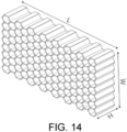
- a thickness t is much smaller than a frame length 1, so some calculations may be simplified.
- the honeycomb structure is a regular hexagonal honeycomb core
- the H-direction compression modulus of the regular hexagonal honeycomb core directly reflects the out-of-plane load-bearing capacity determined by the load-bearing area dose.
- E f 1.54 t l E s ; where E f is the compression modulus of the honeycomb core, t is the thickness of the honeycomb wall material, 1 is the side length of the regular hexagonal honeycomb core grid, and E s is the elastic modulus of the manufacturing material of the honeycomb core.
- honeycomb structure in the skin-honeycomb sandwich layer structure may be designed with the honeycomb wall material thickness t, the honeycomb core grid side length 1, and honeycomb wall material, so that the compression modulus, shear modulus, and compressive strength of the honeycomb structure are within the predetermined ranges.
- calculation and design may be carried out according to the above formulas of the compression modulus, the shear modulus, and the compressive strength to obtain a honeycomb structure with good performance.
- the disclosure provides an additive manufacturing device for a complex structure of a fiber-reinforced composite material.
- the manufacturing device for the complex structure of the fiber-reinforced composite material is configured to implement the additive manufacturing method for the complex structure of the fiber-reinforced composite material.
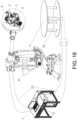
- the additive manufacturing device includes a host computer 11, a robot 21, a turntable 22, and a printing unit group A.
- the robot 21, the turntable 22, and the printing unit group A are electrically connected to the host computer 11, that is, the signal connection can be connected through a signal line.
- the printing unit group A is mechanically connected to robot 21.
- the printing unit group A includes a fiber placement unit 3, a water-soluble resin material printing unit 4, and a fiber-reinforced composite material printing unit 5.
- the host computer in this additive manufacturing device is used for comprehensive control of the additive manufacturing device.
- the host computer may control the robot to move in three dimensions to drive the printing unit group to move in three dimensions.
- the turntable is a printing table used to support a printed molded part.
- the host computer may control the turntable to move with multiple degrees of freedom, and the host computer may also control the printing unit group to perform a printing operation.
- the printing unit group is integrated with the fiber placement unit for fiber tow placement to form the upper skin structure and the lower skin structure.
- the water-soluble resin material printing unit is configured to achieve variable flow printing of the supporting mold.
- the fiber-reinforced composite printing unit is configured to continuously print the fiber-reinforced resin matrix composite material to form the honeycomb structure.
- the additive manufacturing device is integrated with three printing units, which can sequentially print the supporting mold, the skin structure, and the honeycomb structure to form the skin-honeycomb sandwich layer structure. In this way, the replacement of the print head may be eliminated and the operation is convenient.
- the disclosure provides an effective additive manufacturing method and device for a complex structure of a continuous fiber-reinforced resin matrix composite material for a large-scale skin-honeycomb sandwich layer structure part for aerospace.
- a complex part of the continuous fiber-reinforced resin matrix composite material such as a large skin-honeycomb sandwich layer structure for aerospace use may be quickly manufactured without specific molds.
- part manufacturing time and costs may be significantly decreased while ensuring the mechanical properties.
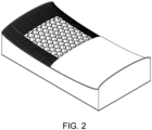
- a complex skin-honeycomb sandwich layer structure part as shown in FIG. 2 is printed.
- the method includes the following steps.
- Data such as the three-dimensional model of the printed part, application requirements, and performance indicators are imported into the host computer. According to the result generated by the host computer, a corresponding material fiber storage is placed. The printing table and the printing nozzle begin to be preheated to the specified temperature, and the monitoring system starts to work.
- the fused deposition modeling process is used, and a water-soluble resin roll is used on a multi-degree-of-freedom heated turntable to print the forming mold, that is, the supporting mold.
- the selected continuous fiber-reinforced resin matrix composite material fiber storage is used to place the fiber tow on the forming mold to form the lower skin structure.
- the fused deposition process is used to print the honeycomb structure on the surface to be molded using the continuous fiber-reinforced resin matrix composite material fiber storage selected at the beginning.
- Laser heating and constant force rolling are continuously used to assist the fiber placement process.
- the fiber tow is placed again on the honeycomb structure to form the upper skin structure.
- the monitoring system monitors printing defects in real-time and transmits data to the host computer, and the host computer then decides independently whether to repair or terminate printing.
- the printing process is monitored in real-time by a monitoring system including a CCD camera and temperature and mechanics sensors and the like integrated with a deep learning algorithm.
- the monitoring system communicates with the host computer in real-time and decides independently whether to repair defects or terminate printing.
- the part is put into a special dissolving solution to remove the water-soluble resin mold.
- the nozzle variable diameter water-soluble resin material printing unit 4 is shown in FIG. 21 .
- a driving motor 440 drives a gear 439 to rotate, so that the diameter of the nozzle may be changed in real-time, and the rotation speed of an extrusion driving motor 442 may also be changed so that the extrusion flow rate of the molten resin is adjusted.
- the driving motor 440 works to increase the diameter of the nozzle, and at the same time increases the rotation speed of the extrusion driving motor 442 to increase the extrusion flow rate of the nozzle and improve the part molding efficiency. Where the thickness of the sliced layer is small, the driving motor 440 works to reduce the diameter of the nozzle, and at the same time reduces the rotation speed of the extrusion drive motor 442. In this way, the extrusion flow rate of the nozzle is reduced and the continuity of the printing process is ensured.
- the disclosure provides an additive manufacturing device for a complex structure of a continuous fiber-reinforced resin matrix composite material.
- the device includes a control unit 1, a movement execution unit 2, and a printing unit group A.
- the control unit includes a host computer 11 and a communication cable 12, and the host computer 11 may be an industrial computer.
- the movement execution unit 2 includes a six-axis industrial robot 21 and a multi-degree-of-freedom turntable 22.
- the printing unit group A includes a continuous fiber-reinforced resin matrix composite material fiber placement unit 3, a water-soluble resin material printing unit 4, and a fiber-reinforced composite material printing unit 5.
- the continuous fiber-reinforced resin matrix composite material fiber placement unit 3 includes a feeding mechanism 31, a lining paper recovery mechanism 32, a tow guiding mechanism 33, a tow clamping mechanism 34, a tow re-transporting mechanism 35, a tow shearing mechanism 36, a pressure roller mechanism 37, a laser heater 38, and an image collector 39.
- the feeding mechanism includes a material fiber storage 311, a fiber storage sleeve 312, a tension monitor 313, and a fiber storage remaining amount monitor 314.
- the lining paper recovery mechanism 32 includes a lining paper recovery sleeve 321.
- the tow guiding mechanism 33 includes a guiding wheel 331 for first guiding around the lining paper recovery sleeve, a guiding wheel 332 that continues to transport secondary guiding, and a guiding wheel 333 for third guiding that forms a specific angle with the guiding wheel of the secondary guiding to limit the guiding of the tow.
- the tow clamping mechanism 34 includes a cylinder 341 and a clamping wheel 342 corresponding to the number of tows.
- the tow re-transporting mechanism 35 includes a cylinder 351, a transporting roller 352, and a driving motor 353 corresponding to the number of tows.
- the tow shearing mechanism 36 includes a cylinder 361, a cutter 362, a tow clamping plate 363, and a tow material outage monitor 364 corresponding to the number of tows.
- the pressure roller mechanism 37 may include a pressure roller 371 capable of rolling multi-strand carbon fiber composite tows, a constant pressure monitor 372, and a pressure cylinder 373.
- the laser heater 38 includes a laser output device 381 with a temperature that can melt the resin matrix on the surface of the continuous carbon fiber composite material, a temperature monitor 382, and a laser output device clamping plate 383.
- the image collector 39 includes a CCD camera 391 and an image processing and analysis device 392.
- the water-soluble resin material printing unit 4 includes a feeding mechanism 41, a nozzle lifting mechanism 42, an extrusion mechanism 43, a tow guiding mechanism 44, and an image collector 45.
- the feeding mechanism 41 includes a water-soluble resin material fiber storage 411 and a fiber storage remaining amount monitor 412.
- the nozzle lifting mechanism 42 includes a lead screw 421, a driving motor 422, a nozzle connecting plate 423, and a sliding rail block 424.
- the extrusion mechanism 43 includes a heating block 431, a heat sink 432, a fan 433, an extrusion screw 434, a nozzle 435, a material outage monitor 436, a temperature detector 437, a tow flow rate adjustment device 438, a gear 439, and a drive motor 440.
- the tow guiding mechanism 44 includes a guiding pulley and a driving motor 442.
- the image collector 45 includes a CCD camera 451 and an image processing and analysis device 452.
- a continuous fiber-reinforced resin matrix composite material printing unit that is, the fiber-reinforced composite material printing unit 5, includes a feeding mechanism 51, a nozzle lifting mechanism 52, an extrusion mechanism 53, and an image collector 54.
- the feeding mechanism 51 includes a material fiber storage 511 and a fiber storage remaining amount monitor 512.
- the nozzle lifting mechanism 52 includes a lead screw 521, a driving motor 522, and a nozzle connecting plate 523.
- the extrusion mechanism 53 includes a heating block 531, a heat sink 532, a fan 533, an extrusion gear 534, a nozzle 535, a material outage monitor 536, a temperature monitor 537, and a driving motor 538.
- the image collector 54 includes a CCD camera 541 and an image processing and analysis device 542.
- the six-axis industrial robot 21 and the multi-degree-of-freedom turntable 22 in the movement execution unit 2 work together, additive manufacturing with eight degrees of freedom may be achieved, and the "step effect" in the conventional additive manufacturing process is reduced.
- the continuous fiber-reinforced resin matrix composite material fiber placement unit 3 is responsible for completing the additive manufacturing process of the lower skin and the upper skin.
- the number of tows is controlled by the tow shearing mechanism 36 and the tow clamping mechanism 34 and can be adjusted in real-time to optimize the forming quality.
- the water-soluble resin material printing unit 4 sends signals from the host computer 11 to the driving motor 440 and the driving motor 442 to regulate the diameter of the nozzle and change the tow feeding rate in real-time. In this way, the molding accuracy as well as the molding efficiency are improved.
- the continuous fiber-reinforced resin matrix composite material printing unit that is, the fiber-reinforced composite material printing unit 5, combines the proposed novel honeycomb structure filling algorithm to optimize the honeycomb structure molding quality and achieve tightly bonded printing of the honeycomb structure on the lower skin structure.
- the CCD camera combines deep learning algorithms with real-time communication with the host computer to monitor the printing process in real-time, repair defects, and terminate printing in a timely manner.
- the additive manufacturing method and manufacturing device for the complex structure of the fiber-reinforced composite material provided by the disclosure are not only suitable for continuous fibers but also for other forms of fibers, such as chopped fibers, etc., and are not specifically limited.
- the entire printing process of skin-honeycomb sandwich layer structure parts is monitored in real-time, printing defects may be repaired, and printing may be terminated in real-time to avoid waste of printing materials and to reduce manufacturing costs.
- the combination of the six-axis industrial robot and the multi-degree-of-freedom turntable may effectively eliminate the "step effect" defect commonly found in the currently available additive manufacturing process.
- the printing path may be adjusted at any time according to the material fiber direction and the mechanics performance requirements of the part, so as to provide favorable strength and stiffness distribution of the entire part.
Landscapes
- Chemical & Material Sciences (AREA)
- Engineering & Computer Science (AREA)
- Materials Engineering (AREA)
- Manufacturing & Machinery (AREA)
- Physics & Mathematics (AREA)
- Mechanical Engineering (AREA)
- Optics & Photonics (AREA)
Abstract
Description
- The disclosure belongs to the technical field related to additive manufacturing of composite materials, and in particular, relates to an additive manufacturing method and manufacturing device for a complex structure of a fiber-reinforced composite material.
- As early as the 1980s, 3% to 5% para-aramid honeycomb sandwich layer structure fiber-reinforced composite materials were used on Boeing 767 and Airbus A320 commercial aircraft. The floor structure on the European giant aircraft "Airbus A380" is largely made of honeycomb sandwich layer structure composite materials. Excellent material properties enable the A380's operating life to reach 20,000 hours. Compared to other structures of the same thickness, the skin-honeycomb sandwich layer structure composite materials have an excellent weight reduction effect while maintaining high stiffness and strength, and the weight reduction can reach more than 50%. In addition, the skin-honeycomb sandwich layer structure composite materials also have excellent fatigue resistance, heat insulation, and impact resistance. Therefore, the skin-honeycomb sandwich structure composite materials have received increasing attention in aerospace and other fields and have been widely used in parts such as wings, fuselages, tails, and radomes.
- At present, most of the preparation of the skin-honeycomb sandwich layer structure parts is inseparable from manual preparation. The individually formed honeycomb sandwich layer is manually placed on the lower skin structure, and then the upper skin structure and the honeycomb sandwich layer structure are aligned manually or through a machine. The upper and lower skin structures and the honeycomb sandwich layer are then pasted together to produce the skin-honeycomb sandwich layer structure parts. In the currently available production processes of complex composite structures such as the skin-honeycomb sandwich structures, there are problems such as low degree of automation, low accuracy of molded parts, high labor intensity, and poor quality stability of parts.
- In response to the above defects or the need for improvement, the disclosure provides an additive manufacturing method and manufacturing device for a complex structure of a fiber-reinforced composite material capable of solving problems such as low degree of automation, low accuracy of molded parts, high labor intensity, and poor quality stability of parts found in the currently-available production processes of complex composite structures such as the skin-honeycomb sandwich structures, so that the degree of automation in preparing skin-honeycomb sandwich layer structure parts is improved, the parts are lightweight, the mechanical properties are ensured, and the part manufacturing time and costs are significantly decreased.
- To achieve the above, in an aspect of the disclosure, the disclosure provides an additive manufacturing method for a complex structure of a fiber-reinforced composite material. The complex structure is a skin-honeycomb sandwich layer structure, and the manufacturing method includes the following steps.
- In S1, a supporting mold is printed through a fused deposition additive manufacturing process and by using a water-soluble resin material.
- In S2, a fiber automatic placement process is assisted through laser heating and constant force rolling, and fiber tow placement is performed on the supporting mold to form a lower skin structure by using a fiber-reinforced pre-preg material.
- In S3, a honeycomb structure is printed and formed on the surface of the lower skin structure through the fused deposition additive manufacturing process and by using the fiber-reinforced composite material.
- In S4, the fiber tow placement is performed on the honeycomb structure by adopting the process in S2 to form an upper skin structure.
- In S5, the supporting mold is removed to obtain the integrally-formed skin-honeycomb sandwich layer structure.
- According to another aspect of the disclosure, the disclosure further provides an additive manufacturing device for a complex structure of a fiber-reinforced composite material including a host computer, a robot, a turntable, and a printing unit group. The robot, the turntable, and the printing unit group are connected to the host computer. The printing unit group is connected to the robot. The printing unit group includes a fiber placement unit, a water-soluble resin material printing unit, and a fiber-reinforced composite material printing unit.
- In general, when the above technical solution provided by the disclosure is compared to the related art, in the additive manufacturing method and manufacturing device for the complex structure of the fiber-reinforced composite material:
- 1. It is proposed to first use the water-soluble resin material to print and form the supporting mold and remove the supporting mold at last. In this way, the problems of difficulty in custom mold iteration and mold customization in the current fiber placement technology are solved. In the manufacturing method, the integrated skin-honeycomb sandwich layer structure is manufactured through additive manufacturing, so that the automation level of preparing skin-honeycomb sandwich layer structure parts is improved, labor costs are saved, and production costs are reduced.
- 2. When the supporting mold is printed, the curved surface slicing method and variable flow rate printing method are proposed, which are beneficial to improving printing accuracy and printing efficiency.
- 3. The proposed honeycomb structure printing path-filling algorithm can achieve efficient and accurate printing and molding of the honeycomb structure.
- 4. Through the real-time monitoring of the placement pressure of the anti-collapse roller and the arrangement of the pressure roller cross-section, the collapse of the hollow part of the honeycomb structure that occurs during the skin placement process may be effectively reduced, and the mechanics properties and surface quality of the skin-honeycomb structure parts may be effectively improved.
-
-
FIG. 1 is a schematic chart of an additive manufacturing method for a complex structure of a fiber-reinforced composite material provided by the disclosure. -
FIG. 2 is a schematic view of a skin-honeycomb sandwich layer structure by the disclosure. -
FIG. 3 is a schematic view of a slicing method of a supporting mold provided by the disclosure. -
FIG. 4 is a schematic view of a curved surface slicing method of the supporting mold provided by the disclosure. -
FIG. 5 is a schematic view of a planar structure of a honeycomb structure provided by the disclosure. -
FIG. 6 is a schematic view of the periodic division of the planar structure of the honeycomb structure provided by the disclosure. -
FIG. 7 is a schematic view of the periodic division of odd-numbered curve segments in the planar structure of the honeycomb structure provided by the disclosure. -
FIG. 8 is a schematic view of the coordinate acquisition of periodic line segments of the odd-numbered curve segments provided by the disclosure. -
FIG. 9 is a schematic view of the coordinate acquisition of periodic line segments of even-numbered curve segments provided by the disclosure. -
FIG. 10 is a schematic view of compaction operation by a pressure roller provided by the disclosure. -
FIG. 11 is a schematic structural view of the pressure roller provided by the disclosure. -
FIG. 12 is a transverse schematic view of the pressure roller during the compaction operation provided by the disclosure. -
FIG. 13 is a lateral schematic view of the pressure roller during the compaction operation provided by the disclosure. -
FIG. 14 is a schematic view of the honeycomb structure provided by the disclosure. -
FIG. 15 is a schematic chart of the actual implementation of the additive manufacturing method for the complex structure of the fiber-reinforced composite material provided by the disclosure. -
FIG. 16 is a schematic view of an additive manufacturing device for a complex structure of a fiber-reinforced composite material provided by the disclosure. -
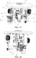
FIG. 17 is a first schematic view of a printing unit group in the additive manufacturing device provided by the disclosure. -
FIG. 18 is a second schematic view of the printing unit group in the additive manufacturing device provided by the disclosure. -
FIG. 19 is a first schematic view of a fiber placement unit provided by the disclosure. -
FIG. 20 is a second schematic view of the fiber placement unit provided by the disclosure. -
FIG. 21 is a schematic view of a water-soluble resin material printing unit provided by the disclosure. -
FIG. 22 is a schematic view of a fiber-reinforced composite material printing unit provided by the disclosure. - In the accompanying drawings, the same reference numerals are used to represent identical or similar elements or structures, where:
- 1: control unit, 11: host computer, 12: communication cable, 2: movement execution unit, 21: robot, 22: turntable, A: printing unit group, 3: fiber placement unit, 4: water-soluble resin material printing unit, 5: fiber-reinforced composite material printing unit, 31: feeding mechanism, 32: lining paper recovery mechanism, 33: tow guiding mechanism, 34: tow clamping mechanism, 35: tow re-transporting mechanism, 36: tow shearing mechanism, 37: pressure roller mechanism, 38: laser heater, 39: image collector, 311: material fiber storage, 312: fiber storage sleeve, 313: tension monitor, 314: fiber storage remaining amount monitor, 321: lining paper recovery sleeve, 331, 332, and 333: guiding wheel, 341, 351, and 361: cylinder, 342: clamping wheel, 352: transporting roller, 353: driving motor, 362: cutter, 363: tow clamping plate, 364: tow material outage monitor, 371: pressure roller, 372: constant pressure monitor, 373: pressure cylinder, 381: laser output device, 382: temperature monitor, 383: laser output device clamping plate, 391: camera, 392: image processing and analysis device,
- 41: feeding mechanism, 42: nozzle lifting mechanism, 43: extrusion mechanism, 44: tow guiding mechanism, 45: image collector, 411: water-soluble resin material fiber storage, 412: fiber storage remaining amount monitor, 421: lead screw, 422: driving motor, 423: nozzle connecting plate, 424: sliding rail block, 431: heating block, 432: heat sink, 433: fan, 434: extrusion screw, 435: nozzle, 436: material outage monitor, 437: temperature detector, 438: tow flow rate adjustment device, 439: gear, 440: driving motor, 441: guiding pulley, 442: driving motor, 451: camera, 452: image processing and analysis device,
- 51: feeding mechanism, 52: nozzle lifting mechanism, 53: extrusion mechanism, 54: image collector, 511: material fiber storage, 512: fiber storage remaining amount monitor, 521: lead screw, 522: driving motor, 523: nozzle connecting plate, 531: heating block, 532: heat sink, 533: fan, 534: extrusion gear, 535: nozzle, 536: material outage monitor, 537: temperature monitor, 538: driving motor, 541: camera, 542: image processing and analysis device.
- In order to make the objectives, technical solutions, and advantages of the disclosure clearer and more comprehensible, the disclosure is further described in detail with reference to the drawings and embodiments. It should be understood that the specific embodiments described herein serve to explain the invention merely and are not used to limit the invention. In addition, the technical features involved in the various embodiments of the invention described below can be combined with each other as long as the technical features do not conflict with each other.
- With reference to
FIG. 1 andFIG. 2 , the disclosure provides an additive manufacturing method for a complex structure of a fiber-reinforced composite material, where the complex structure is a skin-honeycomb sandwich layer structure and the like. As shown inFIG. 2 , the skin-honeycomb sandwich layer structure includes a lower skin structure, an upper skin structure, and a honeycomb structure arranged in a middle sandwich layer. The manufacturing method includes the following steps. - In S1, a supporting mold is printed through a fused deposition additive manufacturing process and by using a water-soluble resin material.
- In S2, a fiber automatic placement process is assisted through laser heating and constant force rolling, and fiber tow placement is performed on the supporting mold to form the lower skin structure by using a fiber-reinforced pre-preg material.
- In S3, a honeycomb structure is printed and formed on the surface of the lower skin structure through the fused deposition additive manufacturing process and by using the fiber-reinforced composite material.
- In S4, the fiber tow placement is performed on the honeycomb structure by adopting the process in S2 to form the upper skin structure.
- In S5, the supporting mold is removed to obtain the integrally-formed skin-honeycomb sandwich layer structure.
- The manufacturing method provided by the disclosure uses an additive manufacturing method to integrally form the skin-honeycomb sandwich layer structure. The honeycomb structure is directly formed on the surface of the lower skin structure by printing, and the upper skin structure is directly formed on the honeycomb structure. In this way, the process of aligning and bonding a skin structure and a honeycomb sandwich layer requiring manual labor or machines in the related art can be eliminated, and the problems of inaccurate alignment and loose connection between the honeycomb structure and the skin structure in the relater art are solved. As such, labor intensity is lowered, the level of automation of the production process is improved, the accuracy of molded parts is enhanced, the level of integration of molded parts is improved, and the strength and quality stability of molded parts are further improved.
- Further, in the additive manufacturing method for the complex structure of the fiber-reinforced composite material provided by the disclosure, before the skin structure and honeycomb structure are printed, the supporting mold is printed with the water-soluble resin material, and the lower skin structure is automatically placed and treated as a surface to be molded by using the fiber-reinforced resin pre-preg material. That is, the skin structure is formed by automatically placing a fiber tow through a corresponding fiber placement unit. The fiber-reinforced resin matrix composite material is then used to print the honeycomb structure on the surface to be molded. The fiber-reinforced resin pre-preg material is then placed on the honeycomb structure to form the upper skin structure to produce a molded part, and finally, a water-soluble resin mold is removed through a special dissolving solution.
- In the additive manufacturing method for the complex structure provided by the disclosure, it is proposed to first use the water-soluble resin material to print and form the supporting mold and remove the supporting mold at last. In this way, the problems of difficulty in custom mold iteration and mold customization in the current fiber placement technology are solved. In the manufacturing method, the integrated skin-honeycomb sandwich layer structure is manufactured through additive manufacturing, so that the automation level of preparing skin-honeycomb sandwich layer structure parts is improved, labor costs are saved, and production costs are reduced. Further, the fiber-reinforced resin matrix composite material skin-honeycomb sandwich complex structural parts prepared by the disclosure can replace more metal parts in the aerospace field due to the integrated molding. In this way, the weight of aerospace equipment is reduced and the mechanical and mechanics properties of the equipment are significantly improved.
- Moreover, the fiber-reinforced composite material complex structural parts prepared by this additive manufacturing method are not only suitable for the aerospace field, but also for high-end automobiles and sporting goods, and are not specifically limited.
- Further, before
S 1 is performed, the following is also included. Printing information of the skin-honeycomb sandwich layer structure is inputted into a host computer, and a material fiber storage is placed according to a result generated by the host computer. A printing table and a printing nozzle are preheated to a specified temperature, and a monitoring system is turned on. The printing information of the skin-honeycomb sandwich layer structure can include data information such as a three-dimensional model of a printed part, application requirements, and performance indicators. The host computer can generate a material type required for printing based on the printing information and then place the corresponding material fiber storage. Next, the printing table and printing nozzle need to be preheated to prepare for printing. In addition, the monitoring system may be set up to monitor the printing process in real-time during the printing process, and the monitoring system should be turned on before printing starts. - Further, the fiber-reinforced composite material includes at least one of carbon fiber-reinforced resin matrix composite material, a glass fiber-reinforced resin matrix composite material, and a boron fiber-reinforced resin matrix composite material. The fiber-reinforced composite material includes but is not limited to carbon fiber, glass fiber, boron fiber, and other fiber-reinforced resin matrix composite materials. The fiber-reinforced pre-preg material includes but is not limited to carbon fiber, glass fiber, boron fiber, and other fiber-reinforced resin matrix pre-preg materials.
- Further, the upper surface of the supporting mold in S1 is a curved surface structure, and S1 specifically includes the following.
- In S11, a variation feature of the curved surface structure is extracted, a three-dimensional model of the supporting mold is sliced and layered in a direction from a lower surface to the upper surface, and each sliced layer is set as a curved surface. A curved surface variation feature of each of the sliced layers is consistent with the variation feature of the curved surface structure.
- In S12, each of the sliced layers is sequentially printed in the direction from the lower surface to the upper surface.
- In order to achieve high-accuracy printing of the water-soluble resin material supporting mold with a curved surface structure, the disclosure provides a novel slicing printing method, and a specific process of the slicing method is provided as follows.
- When it is necessary to print a water-soluble resin-supporting mold with a curved surface, if the conventional plane slicing method is used, as shown in
FIG. 3 , the printed mold structure will be affected by the surface step effect and have the defect of poor surface quality. The molding accuracy of subsequent parts will thus be greatly affected. When printing the curved surface of a large mold, in order to ensure the printing accuracy of the mold, the slice thickness needs to be reduced in the conventional method, which will lead to a reduction in printing efficiency. In order to improve the defect of the current slicing method, an innovative slicing method is provided. When slicing is performed, a geometric feature of a surface of a curved surface, that is, the variation feature, is extracted first, which can be understood as the trend of the surface. When slicing is performed, each sliced layer is curved. Each curved sliced layer is an approximation of the corresponding structure of the curved surface and after several layers of similar slices are superimposed, a highly smooth surface required by the resin-supporting mold is formed, as shown inFIG. 4 . - Further, the description of the upper surface and the lower surface in this embodiment is based on the orientation shown in
FIG. 3 and FIG. 4 . In practical applications, the curved surface structure is not limited to being provided on the upper surface of the supporting mold. The curved surface structure may also be provided in other directions of the supporting mold and is not specifically limited. - Furthermore, the disclosure provides a variable flow rate printing method under this slicing method. That is, S12 specifically includes the following. When any of the sliced layers is printed, a discharge flow rate for printing in real-time is adjusted according to the thickness variation of the sliced layer, so that the discharge flow rate of a thicker portion is greater than the discharge flow rate of a thinner portion.
- To be specific, an extruded material flow rate, that is, the discharge flow rate, of the printing nozzle, may be adjusted in real-time according to a thickness of the sliced layer in the variable flow rate printing method, and the printing method specifically includes the following.
- During printing, an extrusion flow rate of a water-soluble resin material melt is adjusted according to a surface adaptive slicing method. Where the thickness of the sliced layer is large, the extrusion flow rate of the nozzle is increased to improve the part molding efficiency. Where the thickness of the sliced layer is small, the extrusion flow rate of the nozzle is reduced to ensure the continuity of the printing process, that is, the continuity of the material discharge.
- Further, S12 also includes the following. A discharge direction is controlled to always be in a normal direction of the surface of a molded part during printing. That is, a print head may be controlled in conjunction with the movement of the robot during printing. In this way, a printing direction is always in the normal direction of the surface of the molded part, the step effect on a molded surface is reduced, the molding accuracy of the molded surface is improved, and a mold with a highly smooth surface is obtained.
- Further, S12 also includes the following. When the sliced layer away from the curved surface is printed, printing is controlled at a discharge speed of a first flow rate. When the sliced layer close to the curved surface is printed, printing is controlled at a discharge speed of a second flow rate. Herein, the first flow rate is greater than the second flow rate.
- That is, the variable flow rate printing method provided by the disclosure also proposes to print with a greater discharge flow rate when printing the sliced layer far away from the curved surface and to print with a smaller discharge flow rate when printing the sliced layer close to the curved surface. Considering that the printing accuracy requirements for a part far away from the curved surface are lower than the printing accuracy requirements for a part close to the curved surface in the disclosure, it is proposed that the part with low printing accuracy requirements may be printed with a greater discharge flow rate to improve efficiency, and the part with high printing accuracy requirements may be printed with a smaller discharge flow rate to improve accuracy.
- Further, a path-filling algorithm of the honeycomb structure in S3 specifically includes the following.
- In S31, periodic processing is performed on a planar structure of the honeycomb structure, and the planar structure is divided into a plurality of repeated units arranged sequentially in an X direction.
- In S32, each of the repeated units is symmetrically divided, where a line of symmetry is in a Y direction, such that each of the repeated units includes an odd-numbered curve segment and an even-numbered curve segment.
- In S33, the odd-numbered curve segment and the even-numbered curve segment in any of the repeated units are periodically divided in the Y direction, and a coordinate path of each periodic line segment is analyzed, so that the coordinate paths of both the odd-numbered curve segment and the even-numbered curve segment in any of the repeated units are obtained.
- In S34, the coordinate paths of both the odd-numbered curve segment and the even-numbered curve segment in any of the repeated units are obtained according to a gap between different repeated units.
- Take the honeycomb structure formed by hexagons adjacent to one another as an example. With reference to
FIG. 5 , the planar structure of the honeycomb structure is a cross-sectional schematic diagram. During printing, the honeycomb structure is formed by stacking the planar structures. In order to facilitate the acquisition of a printing path, the planar structure may be divided periodically in the X direction, and the planar structure may be divided into repeated units arranged sequentially in the X direction. Therefore, for different repeated units, the path variation is the coordinates in the X direction, and the coordinates in the Y direction are cyclically invariant. From this, the path of a single repeated unit may be obtained, and thus the path of the entire planar structure may be obtained. For example, with reference toFigure 6 , acurve ① and acurve ② form a periodic shape, and subsequent paths are to be repeatedly generated with this periodic shape. - Further, each repeated unit is divided symmetrically, and each repeated unit is divided into two curves that are symmetrical about the Y direction. Therefore, each repeated unit includes one odd-numbered curve segment and one even-numbered curve segment. The coordinates of the odd-numbered curve segments in different repeated units in the Y direction are consistent, and the coordinates of the even-numbered curve segments in different repeated units in the Y direction are consistent. Therefore, the planar structure is the repeated generation of the odd-numbered curve segments in the X direction and the repeated generation of even-numbered curve segments in the X direction. For example, with reference to
FIG. 6 , ①, ③, (5), ⑦... curves are used to form an odd number of curves, and (2), ④, ⑥, ⑧... curves are used to form an even number of curves. Paths are generated through the transformation of the odd-numbered and even-numbered lines. In this way, the odd-numbered curve segments and the even-numbered curve segments are both paths extending in the Y direction, which facilitates printing and is beneficial to improving printing efficiency and molded part quality. - Further, the coordinate path of one of the repeated units in the planar structure may be obtained. As such, since multiple repeated units are periodically arranged in the X direction, the coordinate path of any repeated unit may be extended and obtained according to the gap between different repeated units, and the honeycomb structure may then be printed and obtained. When obtaining the coordinate path of one of the repeated units, the coordinate path of the odd-numbered curve segment and the coordinate path of the even-numbered curve segment may be obtained. For either the odd-numbered curve segments or the even-numbered curve segments, periodic division may be performed in the Y direction. By dividing the curve segment into several periodic line segments arranged periodically in the Y direction, the coordinate path of one periodic line segment is obtained, so that the coordinate path of the entire curve segment may be obtained. For each periodic line segment, the coordinate path of a single periodic line segment may be obtained based on a specific shape feature of the honeycomb structure and a specific set position of a coordinate origin. The coordinate paths of the odd-numbered curve segment and the even-numbered curve segment may then be obtained by extending in the Y direction. By extending the odd-numbered curve segment and the even-numbered curve segment in the X direction, the planar structure may be obtained.
- Further, for any repeated unit, when symmetrical division is performed to form odd-numbered curve segments and even-numbered curve segments, it can be set that the odd-numbered curve segments and the even-numbered curve segments are arranged at intervals. Further, a minimum gap between the odd-numbered curve segments and the even-numbered curve segments is a filled line width during printing. As such, during printing, since the filled line width is the same as the minimum gap, the odd-numbered curve segments and even-numbered curve segments are ultimately connected when printing is completed, so that a closely connected planar structure is formed.
- To be specific, taking the honeycomb structure formed by hexagons adjacent to one another as an example, a honeycomb structure filling algorithm is provided, and the algorithm includes the following process.
- The schematic diagram of honeycomb path filling is shown in
FIG. 5 , and its structure is formed by regular hexagons adjacent to one another. In order to implement the honeycomb-filling algorithm, a honeycomb-filling path needs to be periodized, and the honeycomb path may be generated repeatedly from the repeated units. Next, each repeated unit is divided symmetrically, and the repeated unit is formed by an odd-numbered curve segment (left) and an even-numbered curve segment (right), as shown inFIG. 6 . Thecurve ① and thecurve ② form a periodic shape, and subsequent paths are repeatedly generated with this periodic shape. Further, the ①, ③, (5), ⑦... curves are used to form an odd number of curves, and the ②, ④, ⑥, ⑧... curves are used to form an even number of curves. The paths are generated through the transformation of the odd-numbered and even-numbered lines. - Further, for each of the curve segments (including the odd-numbered curve segment and the even-numbered curve segments), a reference axis in the Y direction may be used as a middle axis. Taking the middle axis as an example, in
curve ① as shown inFIG. 6 , a dotted axis is a middle axis, and a distance between the middle axis and the left and right vertical segments incurve ① is a. A distance between two adjacent vertical straight segments of thecurve ②andcurve ①, that is, the odd-numbered curve segment and the even-numbered curve segment is b, so the distance between the middle axes is 2a+b. Therefore, a middle axis is drawn at an interval of 2a+b in a horizontal direction, and based on the middle axis, different transformations are made to the odd-numbered and even-numbered curve segments to design the honeycomb structure. - Further, with the horizontal direction as the X direction and a vertical direction as the Y direction, periodic division is performed on the odd-numbered curve segment or the even-numbered curve segment with

- The algorithm is designed with the odd-numbered
curve segment ① as the goal, and periodic division is performed on the curve segment. As shown inFIG. 7 , the curve part between the horizontal dotted lines is one period. One periodic line segment of the odd-numbered curve segment is analyzed. As shown inFIG. 8 , the rectangular coordinate system is established with the horizontal line where the initial point is located as the X-axis and with the middle axis as the Y-axis, and the algorithm increases in the Y direction , so that line segments A1B1, B1C1, CiDi, and D1E1 may all be represented by Y-direction coordinates. For the A1B1 line segment, since x A1 -x B1 =2α, when
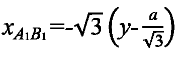

1 C1 =-a. When


1 E1 =a. The periodic extension is carried out with the Y-direction period
curve ① is formed. - Further, for the even-numbered curve segment (2), as shown in
FIG. 9 , the X-direction coordinate of the middle axis is x2=2a+b. For a single period, when

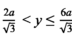
2 C2 =a+x2. When
2 D2 =-

2 E2 =-a+x2. The periodic extension is carried out with the Y-direction period Ty=
curve ② is formed. - Further, for a nth curve, the X-direction coordinate of the middle axis is xn=(2a+b)(n-1), and when





- Using the above method to periodically extend the Y and X directions, the honeycomb structure may be formed. In particular, a parameter involved in the algorithm is half a line gap of filled lines, and a parameter b is a line width of the filled lines.
- Further, S2 and S4 specifically include the following. The fiber tow placement is performed through laser heating, a compaction operation is performed during the fiber tow placement process by using a pressure roller, and a real-time placement pressure exerted by the pressure roller is monitored, so that the real-time placement pressure is consistent with a predetermined placement pressure.
- That is, laser heating and constant force rolling are used to assist in the fiber tow placement. Laser heating is helpful to make the fiber tow more evenly heated and improve fiber placement efficiency. Constant force rolling uses constant placement pressure to roll the placed fiber tow, which is conducive to better ensuring the forming quality of the skin structure, especially for the rolling of the upper skin structure. The use of constant force rolling is beneficial to protecting the honeycomb structure and avoiding damage to the honeycomb structure caused by the rolling compaction operation. To be specific, a pressure sensor may be installed on a pressure transmission path from a driving structure of the pressure roller to the pressure roller, which can monitor the real-time placement pressure exerted by the pressure roller in real-time and adjust the pressure of the pressure roller in real-time according to the predetermined placement pressure so that the real-time placement pressure is consistent with the predetermined placement pressure to achieve constant force compaction.
- Further, the predetermined placement pressure is the designed pressure value exerted by the driving structure of the pressure roller on the pressure roller. In the actual pressure roller pressure control, it is necessary to control the pressure exerted by the driving structure on the pressure roller according to the predetermined placement pressure. The method of obtaining the predetermined placement pressure includes the following.
- A pressure formed by deformation of the pressure roller when the pressure roller compacts the fiber tow is obtained according to the shape information and material information of the pressure roller.
- A functional relationship between the real-time placement pressure exerted by the pressure roller, the pressure formed by the deformation of the pressure roller, and the actual pressure of the fiber tow is obtained.
- The predetermined placement pressure is obtained according to the functional relationship and a predetermined pressure of the fiber tow.
- The pressure roller used in the disclosure is a flexible pressure roller, that is, the surface of the pressure roller has a flexible deformable layer. With reference to
FIG. 10 , in the disclosure, considering that when the pressure roller compacts the fiber tow, the surface of the pressure roller undergoes a certain deformation, and the deformation on the surface of the pressure roller consumes an additional part of the pressure exerted by the driving structure on the pressure roller. That is, not all of the pressure exerted by the driving structure on the pressure roller is transmitted to the surface of the fiber tow, but a small part causes deformation of the surface of the pressure roller. When the compaction operation is performed on the fiber tow, a predetermined pressure value is designed most of the time to be applied to the fiber tow, and the fiber tow can achieve better compaction under this predetermined pressure value. At present, the predetermined pressure value is used directly to control the pressure exerted by the driving structure on the pressure roller most of the time, while the presence of a deformation pressure of the pressure roller is ignored. As such, the actual pressure applied to the surface of the fiber tow is often less than the predetermined pressure value, resulting in the failure to fully achieve the expected compaction effect. - The disclosure proposes that the pressure caused by the deformation of the pressure roller may be calculated and obtained based on a deformation parameter of the pressure roller when the fiber tow is compacted, a shape parameter, and a material parameter of the pressure roller. In this way, when the pressure is applied to the pressure roller, this partial pressure and the predetermined pressure may be considered, so that the final pressure value applied by the pressure roller to the fiber tow is consistent with the predetermined pressure to obtain the expected compaction effect.
- Further, the functional relationship among a real-time placement pressure P exerted by the pressure roller, a pressure Fi formed by the deformation of the pressure roller, and an actual pressure F of the fiber tow is: P=F+Fi.
- Further, the surface of the pressure roller is provided with a honeycomb cross-section shape, and the honeycomb cross-section shape is fitted with the honeycomb structure. The pressure roller used is a flexible pressure roller, and the surface has a honeycomb-shaped cross-section to avoid depression of the fiber tow on the surface of the honeycomb hollow structure when the upper skin structure is compacted. The surface of the pressure roller has a honeycomb-shaped cross-section, that is, a cross-section corresponding to the honeycomb structure, which can achieve the perfect fit with a honeycomb core without causing the hollow part of the honeycomb core to sink due to pressure, as shown in
FIG. 11 . When the fiber is placed and compacted by the press roller, the position is calibrated by a CCD camera, the pressure sensor monitors the constant pressure, and the honeycomb cross-section on the surface of the pressure roller is aligned with a boundary of the formed honeycomb structure, and compaction is then performed. In this way, the load-bearing capacity of the skin-honeycomb sandwich layer structure may be effectively enhanced. - Further, when the driving structure may be a cylinder that applies pressure to the pressure roller and when the pressure roller rolls downwards, the surface of the pressure roller is pressed flush with a top portion of the honeycomb core, causing a certain compression deformation on the surface of the pressure roller, as shown in
FIG. 12 and FIG. 13 . During the contact process between the flexible pressure roller and a fiber tow base material, it is assumed that there is no tension in a contact surface and there is no adhesion when the contracting parties separate, which can be regarded as the non-adhesive elastic contact theory in the classical contact theory. During the skin placement process, the force that causes the flexible pressure roller to deform is shown inFIG. 12 and FIG. 13 , the solid line represents the outline of the flexible pressure roller under pressure, d is the relatively small deformation of the pressure roller, c is the axial width of the flexible pressure roller, q(x) is the distributed line pressure of the flexible pressure roller on the contact surface of the unit cellhoneycomb core width 2e. Assuming that the elastic modulus of the material used in the flexible pressure roller is E and Poisson's ratio is v, and it is calculated based on the non-adhesive elastic contact theory, then:


- According to
FIG. 13 , it can be obtained from the geometric relationship: (R 0 -d)2 +e 2 =R 0 2 . - To simplify the calculation, assuming that the pressure F1 is evenly distributed on the contact surface (q0 is the average value of the pressure q(x)), then the pressure F1 caused by the deformation of the pressure roller is:

- Therefore, the functional relationship among the pressure Fi caused by the deformation of the pressure roller, the real-time placement pressure P, and the actual pressure F on the pre-preg fiber tow is:

- Therefore, after the actual pressure F, that is, the predetermined pressure, expected to be received by the fiber tow is set, the real-time placement pressure P, that is, the predetermined placement pressure, that needs to be applied by the pressure roller, can be calculated through the above formula. During the actual control process of the pressure roller, the pressure exerted by the pressure roller is controlled, so that the real-time placement pressure reaches P and remains constant. Through the real-time monitoring of the placement pressure of the anti-collapse roller and the arrangement of the pressure roller cross-section, the collapse of the hollow part of the honeycomb structure that occurs during the skin placement process may be effectively reduced, and the mechanical properties and surface quality of the skin-honeycomb structure parts may be effectively improved.
- Further, the fiber tow placement performed in S2 and S4 specifically includes the following.
- The number of fiber tows in a location with a small curvature is increased, and the number of fiber tows in a location with a large curvature is reduced. When fiber placement is performed in steps S2 and S4, the number of fiber tows may be changed and regulated in real-time as the curvature of the skin structure changes, where the number of fiber tows ranges from 1 to 32. When the fiber tow placement in steps S2 and S4 is performed, the number of placed tows may be changed and regulated in real-time as the skin structure changes. Where the curvature of the skin structure is small, the degree of curving of the skin structure is small, and the number of delivering the tows may be increased accordingly, up to 32 tows, to improve the efficiency of tow placement. Where the curvature of the skin structure is large, the degree of curving of the skin structure is large, the tow shearing mechanism and the pressing mechanism may be used to control the excess tows from being delivered, reduce the number of tows, and ensure printing accuracy.
- Further, the process from S1 to S4 further includes the following.
- The printing process is monitored in real-time, and it is selected to continue printing, repair printing, or terminate printing according to a monitoring result. A camera may be set up above the printing table. During the printing process, the camera is used to collect images of the surface of the molded part and analyze whether there are printing defects, such as gaps, slits, bubbles, and other defects. Based on an analysis result, when the surface quality of the molded part is good, the process of continuing printing is selected. When there is a printing defect and the degree of the defect is small, repairing printing is selected to repeat printing at the defective area. When there is a printing defect and the defect is too severe to be repaired, terminating printing is selected. Real-time monitoring of the printing process helps improve the success rate of printing.
- Further, with reference to
FIG. 11 , the honeycomb cross-section arranged on the surface of the pressure roller is consistent with the shape and size of the honeycomb structure. In this way, when the pressure roller compacts the upper skin structure, the honeycomb cross-section on the surface of the pressure roller may overlap the honeycomb core, so that the connection and compaction between the upper skin structure and the honeycomb structure is more favorably achieved. For a single honeycomb core, a thickness t is much smaller than aframe length 1, so some calculations may be simplified. With reference toFIG. 14 , when the honeycomb structure is a regular hexagonal honeycomb core, the H-direction compression modulus of the regular hexagonal honeycomb core directly reflects the out-of-plane load-bearing capacity determined by the load-bearing area dose. The formula is as follows:
- The L-direction shear modulus of the regular hexagonal honeycomb core is expressed as:

- The W-direction shear modulus of the regular hexagonal honeycomb core is expressed as:

- The honeycomb core compressive strength σc is expressed as:

- Further, the honeycomb structure in the skin-honeycomb sandwich layer structure may be designed with the honeycomb wall material thickness t, the honeycomb core
grid side length 1, and honeycomb wall material, so that the compression modulus, shear modulus, and compressive strength of the honeycomb structure are within the predetermined ranges. To be specific, calculation and design may be carried out according to the above formulas of the compression modulus, the shear modulus, and the compressive strength to obtain a honeycomb structure with good performance. - Further, the disclosure provides an additive manufacturing device for a complex structure of a fiber-reinforced composite material. The manufacturing device for the complex structure of the fiber-reinforced composite material is configured to implement the additive manufacturing method for the complex structure of the fiber-reinforced composite material. With reference to
FIG. 16 , the additive manufacturing device includes ahost computer 11, arobot 21, aturntable 22, and a printing unit group A. Therobot 21, theturntable 22, and the printing unit group A are electrically connected to thehost computer 11, that is, the signal connection can be connected through a signal line. The printing unit group A is mechanically connected torobot 21. The printing unit group A includes afiber placement unit 3, a water-soluble resinmaterial printing unit 4, and a fiber-reinforced compositematerial printing unit 5. - The host computer in this additive manufacturing device is used for comprehensive control of the additive manufacturing device. The host computer may control the robot to move in three dimensions to drive the printing unit group to move in three dimensions. The turntable is a printing table used to support a printed molded part. The host computer may control the turntable to move with multiple degrees of freedom, and the host computer may also control the printing unit group to perform a printing operation. The printing unit group is integrated with the fiber placement unit for fiber tow placement to form the upper skin structure and the lower skin structure. The water-soluble resin material printing unit is configured to achieve variable flow printing of the supporting mold. The fiber-reinforced composite printing unit is configured to continuously print the fiber-reinforced resin matrix composite material to form the honeycomb structure. The additive manufacturing device is integrated with three printing units, which can sequentially print the supporting mold, the skin structure, and the honeycomb structure to form the skin-honeycomb sandwich layer structure. In this way, the replacement of the print head may be eliminated and the operation is convenient.
- Further, in view of the fact that at present, there is no method that can efficiently manufacture a high-quality large-scale skin-honeycomb sandwich layer structure part that meets the requirements, the disclosure provides an effective additive manufacturing method and device for a complex structure of a continuous fiber-reinforced resin matrix composite material for a large-scale skin-honeycomb sandwich layer structure part for aerospace. A complex part of the continuous fiber-reinforced resin matrix composite material such as a large skin-honeycomb sandwich layer structure for aerospace use may be quickly manufactured without specific molds. Compared to a conventional continuous fiber composite part manufacturing method, part manufacturing time and costs may be significantly decreased while ensuring the mechanical properties. In an additive manufacturing method for a complex structure of a continuous fiber-reinforced resin matrix composite material provided by the disclosure, a complex skin-honeycomb sandwich layer structure part as shown in
FIG. 2 is printed. With reference toFIG. 15 , the method includes the following steps. - Data such as the three-dimensional model of the printed part, application requirements, and performance indicators are imported into the host computer. According to the result generated by the host computer, a corresponding material fiber storage is placed. The printing table and the printing nozzle begin to be preheated to the specified temperature, and the monitoring system starts to work.
- The fused deposition modeling process is used, and a water-soluble resin roll is used on a multi-degree-of-freedom heated turntable to print the forming mold, that is, the supporting mold.
- Laser heating and constant force rolling are used to assist the fiber placement process. The selected continuous fiber-reinforced resin matrix composite material fiber storage is used to place the fiber tow on the forming mold to form the lower skin structure.
- The fused deposition process is used to print the honeycomb structure on the surface to be molded using the continuous fiber-reinforced resin matrix composite material fiber storage selected at the beginning.
- Laser heating and constant force rolling are continuously used to assist the fiber placement process. The fiber tow is placed again on the honeycomb structure to form the upper skin structure.
- During each of the above printing steps, the monitoring system monitors printing defects in real-time and transmits data to the host computer, and the host computer then decides independently whether to repair or terminate printing. During the whole process of part printing, the printing process is monitored in real-time by a monitoring system including a CCD camera and temperature and mechanics sensors and the like integrated with a deep learning algorithm. The monitoring system communicates with the host computer in real-time and decides independently whether to repair defects or terminate printing.
- After the part is printed, the part is put into a special dissolving solution to remove the water-soluble resin mold.
- The nozzle variable diameter water-soluble resin
material printing unit 4 is shown inFIG. 21 . A drivingmotor 440 drives agear 439 to rotate, so that the diameter of the nozzle may be changed in real-time, and the rotation speed of anextrusion driving motor 442 may also be changed so that the extrusion flow rate of the molten resin is adjusted. The drivingmotor 440 works to increase the diameter of the nozzle, and at the same time increases the rotation speed of theextrusion driving motor 442 to increase the extrusion flow rate of the nozzle and improve the part molding efficiency. Where the thickness of the sliced layer is small, the drivingmotor 440 works to reduce the diameter of the nozzle, and at the same time reduces the rotation speed of theextrusion drive motor 442. In this way, the extrusion flow rate of the nozzle is reduced and the continuity of the printing process is ensured. - Further, with reference to
FIG. 16 , the disclosure provides an additive manufacturing device for a complex structure of a continuous fiber-reinforced resin matrix composite material. The device includes acontrol unit 1, amovement execution unit 2, and a printing unit group A. The control unit includes ahost computer 11 and acommunication cable 12, and thehost computer 11 may be an industrial computer. Themovement execution unit 2 includes a six-axisindustrial robot 21 and a multi-degree-of-freedom turntable 22. The printing unit group A includes a continuous fiber-reinforced resin matrix composite materialfiber placement unit 3, a water-soluble resinmaterial printing unit 4, and a fiber-reinforced compositematerial printing unit 5. - With reference to
FIG. 17, FIG. 18 ,FIG. 19, and FIG. 20 , the continuous fiber-reinforced resin matrix composite materialfiber placement unit 3 includes afeeding mechanism 31, a liningpaper recovery mechanism 32, atow guiding mechanism 33, atow clamping mechanism 34, atow re-transporting mechanism 35, atow shearing mechanism 36, apressure roller mechanism 37, alaser heater 38, and animage collector 39. The feeding mechanism includes amaterial fiber storage 311, afiber storage sleeve 312, atension monitor 313, and a fiber storage remainingamount monitor 314. The liningpaper recovery mechanism 32 includes a liningpaper recovery sleeve 321. Thetow guiding mechanism 33 includes aguiding wheel 331 for first guiding around the lining paper recovery sleeve, aguiding wheel 332 that continues to transport secondary guiding, and aguiding wheel 333 for third guiding that forms a specific angle with the guiding wheel of the secondary guiding to limit the guiding of the tow. Thetow clamping mechanism 34 includes acylinder 341 and aclamping wheel 342 corresponding to the number of tows. Thetow re-transporting mechanism 35 includes acylinder 351, a transportingroller 352, and a drivingmotor 353 corresponding to the number of tows. Thetow shearing mechanism 36 includes acylinder 361, acutter 362, atow clamping plate 363, and a tow material outage monitor 364 corresponding to the number of tows. Thepressure roller mechanism 37 may include apressure roller 371 capable of rolling multi-strand carbon fiber composite tows, aconstant pressure monitor 372, and apressure cylinder 373. Thelaser heater 38 includes alaser output device 381 with a temperature that can melt the resin matrix on the surface of the continuous carbon fiber composite material, atemperature monitor 382, and a laser outputdevice clamping plate 383. Theimage collector 39 includes aCCD camera 391 and an image processing andanalysis device 392. - With reference to
FIG. 21 , the water-soluble resinmaterial printing unit 4 includes afeeding mechanism 41, anozzle lifting mechanism 42, anextrusion mechanism 43, atow guiding mechanism 44, and animage collector 45. Thefeeding mechanism 41 includes a water-soluble resinmaterial fiber storage 411 and a fiber storage remainingamount monitor 412. Thenozzle lifting mechanism 42 includes alead screw 421, a drivingmotor 422, anozzle connecting plate 423, and a slidingrail block 424. Theextrusion mechanism 43 includes aheating block 431, aheat sink 432, afan 433, anextrusion screw 434, anozzle 435, amaterial outage monitor 436, atemperature detector 437, a tow flowrate adjustment device 438, agear 439, and adrive motor 440. Thetow guiding mechanism 44 includes a guiding pulley and a drivingmotor 442. Theimage collector 45 includes aCCD camera 451 and an image processing andanalysis device 452. - With reference to
FIG. 22 , a continuous fiber-reinforced resin matrix composite material printing unit, that is, the fiber-reinforced compositematerial printing unit 5, includes afeeding mechanism 51, anozzle lifting mechanism 52, anextrusion mechanism 53, and animage collector 54. Thefeeding mechanism 51 includes amaterial fiber storage 511 and a fiber storage remainingamount monitor 512. Thenozzle lifting mechanism 52 includes alead screw 521, a drivingmotor 522, and anozzle connecting plate 523. Theextrusion mechanism 53 includes aheating block 531, aheat sink 532, afan 533, anextrusion gear 534, anozzle 535, amaterial outage monitor 536, atemperature monitor 537, and a drivingmotor 538. Theimage collector 54 includes aCCD camera 541 and an image processing andanalysis device 542. - The six-axis
industrial robot 21 and the multi-degree-of-freedom turntable 22 in themovement execution unit 2 work together, additive manufacturing with eight degrees of freedom may be achieved, and the "step effect" in the conventional additive manufacturing process is reduced. The continuous fiber-reinforced resin matrix composite materialfiber placement unit 3 is responsible for completing the additive manufacturing process of the lower skin and the upper skin. During the skin-forming process, the number of tows is controlled by thetow shearing mechanism 36 and thetow clamping mechanism 34 and can be adjusted in real-time to optimize the forming quality. According to the variable flow rate printing method, the water-soluble resinmaterial printing unit 4 sends signals from thehost computer 11 to the drivingmotor 440 and the drivingmotor 442 to regulate the diameter of the nozzle and change the tow feeding rate in real-time. In this way, the molding accuracy as well as the molding efficiency are improved. The continuous fiber-reinforced resin matrix composite material printing unit, that is, the fiber-reinforced compositematerial printing unit 5, combines the proposed novel honeycomb structure filling algorithm to optimize the honeycomb structure molding quality and achieve tightly bonded printing of the honeycomb structure on the lower skin structure. During the molding process of the three units, the CCD camera combines deep learning algorithms with real-time communication with the host computer to monitor the printing process in real-time, repair defects, and terminate printing in a timely manner. - In the additive manufacturing method for the complex structure of the continuous fiber-reinforced resin matrix composite material provided by the disclosure, laser heating, the constant-force pressure roller-assisted fiber placement process, and the fused deposition modeling process are combined. Further, based on the above, a novel printing method combining slicing and a variable flow nozzle, a complex honeycomb structure printing algorithm, and an anti-collapse pressure roller rolling method are innovatively provided. In this way, the automation level of preparing a complex skin-honeycomb sandwich layer structure part may be quickly improved, and the mechanical properties and surface quality of the part may be enhanced while reducing the weight of the part. This method effectively makes up for the defects in the current manufacturing of skin-honeycomb sandwich layer structure parts. Compared to conventional manufacturing methods, part manufacturing time and costs may be significantly lowered while ensuring mechanical properties.
- The additive manufacturing method and manufacturing device for the complex structure of the fiber-reinforced composite material provided by the disclosure are not only suitable for continuous fibers but also for other forms of fibers, such as chopped fibers, etc., and are not specifically limited.
- Further, In the disclosure, the entire printing process of skin-honeycomb sandwich layer structure parts is monitored in real-time, printing defects may be repaired, and printing may be terminated in real-time to avoid waste of printing materials and to reduce manufacturing costs.
- In the disclosure, the combination of the six-axis industrial robot and the multi-degree-of-freedom turntable may effectively eliminate the "step effect" defect commonly found in the currently available additive manufacturing process. Further, the printing path may be adjusted at any time according to the material fiber direction and the mechanics performance requirements of the part, so as to provide favorable strength and stiffness distribution of the entire part.
- A person having ordinary skill in the art should be able to easily understand that the above description is only preferred embodiments of the disclosure and is not intended to limit the disclosure. Any modifications, equivalent replacements, and modifications made without departing from the spirit and principles of the disclosure should fall within the protection scope of the disclosure.
Claims (10)
- An additive manufacturing method for a complex structure of a fiber-reinforced composite material, characterized in that, the complex structure is a skin-honeycomb sandwich layer structure, and the manufacturing method comprises:S1, printing a supporting mold through a fused deposition additive manufacturing process and by using a water-soluble resin material;S2, assisting a fiber automatic placement process through laser heating and constant force rolling and performing fiber tow placement on the supporting mold to form a lower skin structure by using a fiber-reinforced pre-preg material;S3, printing and forming a honeycomb structure on a surface of the lower skin structure through the fused deposition additive manufacturing process and by using the fiber-reinforced composite material;S4, performing the fiber tow placement on the honeycomb structure by adopting the process in S2 to form an upper skin structure; andS5, removing the supporting mold to obtain the integrally-formed skin-honeycomb sandwich layer structure.
- The additive manufacturing method for the complex structure of the fiber-reinforced composite material according to claim 1, characterized in that, an upper surface of the supporting mold in S1 is a curved surface structure, and S1 specifically comprises:S11, extracting a variation feature of the curved surface structure, slicing and layering a three-dimensional model of the supporting mold in a direction from a lower surface to the upper surface, and setting each of sliced layers as a curved surface, wherein a curved surface variation feature of each of the sliced layers is consistent with the variation feature of the curved surface structure; andS12, sequentially printing each of the sliced layers in the direction from the lower surface to the upper surface.
- The additive manufacturing method for the complex structure of the fiber-reinforced composite material according to claim 2, characterized in that, S12 specifically comprises:
when any of the sliced layers is printed, adjusting discharge flow rates for printing in real-time according to thickness variations of the sliced layer, so that the discharge flow rate of a thicker portion is greater than the discharge flow rate of a thinner portion. - The additive manufacturing method for the complex structure of the fiber-reinforced composite material according to any one of claims 1 to 3, characterized in that, a path-filling algorithm of the honeycomb structure in S3 specifically is:performing periodic processing on a planar structure of the honeycomb structure and dividing the planar structure into a plurality of repeated units arranged sequentially in an X direction;symmetrically dividing each of the repeated units, wherein a line of symmetry is in a Y direction, such that each of the repeated units comprises an odd-numbered curve segment and an even-numbered curve segment;periodically dividing the odd-numbered curve segment and the even-numbered curve segment into any of the repeated units in the Y direction and analyzing a coordinate path of each periodic line segment to obtain coordinate paths of both the odd-numbered curve segment and the even-numbered curve segment in any of the repeated units; andobtaining the coordinate paths of both the odd-numbered curve segment and the even-numbered curve segment in any of the repeated units according to a gap between different repeated units.
- The additive manufacturing method for the complex structure of the fiber-reinforced composite material according to any one of claims 1 to 3, characterized in that, S2 and S4 specifically comprise:
performing the fiber tow placement through laser heating, performing a compaction operation during the fiber tow placement process by using a pressure roller, and monitoring a real-time placement pressure exerted by the pressure roller on the fiber tow, so that the real-time placement pressure is consistent with a predetermined placement pressure. - The additive manufacturing method for the complex structure of the fiber-reinforced composite material according to claim 5, characterized in that, a method of obtaining the predetermined placement pressure is:obtaining a pressure formed by deformation of the pressure roller when the pressure roller compacts the fiber tow according to shape information and material information of the pressure roller;obtaining a functional relationship among the real-time placement pressure exerted by the pressure roller, the pressure formed by the deformation of the pressure roller, and an actual pressure of the fiber tow; andobtaining the predetermined placement pressure according to the functional relationship and a predetermined pressure of the fiber tow.
- The additive manufacturing method for the complex structure of the fiber-reinforced composite material according to claim 5, characterized in that, a surface of the pressure roller is provided with a honeycomb cross-section shape, and the honeycomb cross-section shape is fitted with the honeycomb structure.
- The additive manufacturing method for the complex structure of the fiber-reinforced composite material according to any one of claims 1 to 3, characterized in that, the fiber tow placement performed in S2 and S4 specifically comprises:
increasing a number of fiber tows in a location with a small curvature and reducing a number of fiber tows in a location with a large curvature. - The additive manufacturing method for the complex structure of the fiber-reinforced composite material according to any one of claims 1 to 3, characterized in that, the process from S1 to S4 further comprises:
monitoring the printing process in real-time and selecting to continue printing, repair printing, or terminate printing according to a monitoring result. - An additive manufacturing device for a complex structure of a fiber-reinforced composite material, characterized in that, comprises a host computer, a robot, a turntable, and a printing unit group, wherein the robot, the turntable, and the printing unit group are electrically connected to the host computer, the printing unit group is connected to the robot, and the printing unit group comprises a fiber placement unit, a water-soluble resin material printing unit, and a fiber-reinforced composite material printing unit.
Applications Claiming Priority (2)
| Application Number | Priority Date | Filing Date | Title |
|---|---|---|---|
| CN202310457581.0A CN116423826A (en) | 2023-04-25 | 2023-04-25 | Additive manufacturing method and manufacturing device for complex structure of fiber-reinforced composite material |
| PCT/CN2023/095683 WO2024221516A1 (en) | 2023-04-25 | 2023-05-23 | Additive manufacturing method and device for complex structure of fiber reinforced composite material |
Publications (2)
| Publication Number | Publication Date |
|---|---|
| EP4477388A4 EP4477388A4 (en) | 2024-12-18 |
| EP4477388A1 true EP4477388A1 (en) | 2024-12-18 |
Family
ID=87083149
Family Applications (1)
| Application Number | Title | Priority Date | Filing Date |
|---|---|---|---|
| EP23844060.6A Pending EP4477388A1 (en) | 2023-04-25 | 2023-05-23 | Additive manufacturing method and device for complex structure of fiber reinforced composite material |
Country Status (3)
| Country | Link |
|---|---|
| EP (1) | EP4477388A1 (en) |
| CN (1) | CN116423826A (en) |
| WO (1) | WO2024221516A1 (en) |
Families Citing this family (4)
| Publication number | Priority date | Publication date | Assignee | Title |
|---|---|---|---|---|
| CN117841238A (en) * | 2023-12-22 | 2024-04-09 | 北京机科国创轻量化科学研究院有限公司 | Integrated forming method of placement and printing of composite material components |
| CN119502336A (en) * | 2024-11-07 | 2025-02-25 | 中国飞机强度研究所 | Method and device for manufacturing arbitrary curvature thermoplastic composite honeycomb sandwich structure |
| CN119734341B (en) * | 2025-01-07 | 2025-11-18 | 河北工业大学 | Additive manufacturing method of solid waste base brick mud structure composite material |
| CN120792147A (en) * | 2025-06-23 | 2025-10-17 | 成都飞机工业(集团)有限责任公司 | Manufacturing method of composite material part with pointed cone-shaped cavity and thin-wall structure |
Family Cites Families (19)
| Publication number | Priority date | Publication date | Assignee | Title |
|---|---|---|---|---|
| CN103722171B (en) * | 2013-12-25 | 2016-06-01 | 合肥工业大学 | A kind of honeycomb fashion laser scanning method for selective laser sintering |
| CN104590397B (en) * | 2015-01-12 | 2017-05-10 | 湖南湖大艾盛汽车技术开发有限公司 | Application method for section structure of lightweight car body |
| CN105608275B (en) * | 2015-12-23 | 2018-08-14 | 南京航空航天大学 | A kind of generation method of printing path for model lightweight 3 D-printing |
| US10906248B2 (en) * | 2016-12-20 | 2021-02-02 | Textron Innovations, Inc. | Additive manufacturing method for improved core structure |
| US10392097B2 (en) * | 2017-02-16 | 2019-08-27 | The Boeing Company | Efficient sub-structures |
| CN106738891A (en) * | 2017-03-01 | 2017-05-31 | 机械科学研究总院先进制造技术研究中心 | A kind of continuous fiber composite material increasing material manufacturing method of interlaminar improvement |
| PL3740373T3 (en) * | 2018-01-18 | 2022-11-14 | Arctic Biomaterials Oy | Fiber-reinforced 3d printing |
| CN109049754A (en) * | 2018-08-20 | 2018-12-21 | 江苏大学 | A kind of double light source temperature auxiliary carbon fiber prepreg laying device and methods of laser |
| CN112639010A (en) * | 2018-08-21 | 2021-04-09 | 巴斯夫欧洲公司 | Additive printing filament material |
| CN109080167B (en) * | 2018-09-30 | 2019-11-19 | 浙江大学 | A method for in-situ additive manufacturing of continuous fiber composite structural parts |
| US11260582B2 (en) * | 2018-10-16 | 2022-03-01 | Divergent Technologies, Inc. | Methods and apparatus for manufacturing optimized panels and other composite structures |
| US11745440B2 (en) * | 2020-04-03 | 2023-09-05 | The Boeing Company | Automated lamination system and method for embedding printed electronic elements in a composite structure |
| CN111941836B (en) * | 2020-07-06 | 2021-12-14 | 东北大学 | A composite 3D printing porous nozzle and method integrating silk laying, forming and cutting |
| CN112140528A (en) * | 2020-09-02 | 2020-12-29 | 北京机科国创轻量化科学研究院有限公司 | Continuous fiber additive manufacturing method with Z-direction reinforcing function |
| CN112644100A (en) * | 2020-11-26 | 2021-04-13 | 西安交通大学 | Large-curvature honeycomb interlayer composite material structure and integrated forming method thereof |
| CN114013069B (en) * | 2021-10-22 | 2022-12-02 | 华中科技大学 | Automatic laying and fused deposition compounding process of fiber reinforced thermoplastic material |
| CN114292115A (en) * | 2021-12-31 | 2022-04-08 | 华中科技大学 | Reinforced SiC composite material preparation method based on robot laser additive manufacturing |
| CN114407352A (en) * | 2022-01-30 | 2022-04-29 | 西安交通大学 | Continuous fiber 3D printer and method for manufacturing composite material component |
| CN115972572B (en) * | 2023-01-06 | 2024-12-27 | 华中科技大学 | Robot-assisted laser additive manufacturing system for reinforcing continuous fiber composite layers |
-
2023
- 2023-04-25 CN CN202310457581.0A patent/CN116423826A/en active Pending
- 2023-05-23 EP EP23844060.6A patent/EP4477388A1/en active Pending
- 2023-05-23 WO PCT/CN2023/095683 patent/WO2024221516A1/en not_active Ceased
Also Published As
| Publication number | Publication date |
|---|---|
| CN116423826A (en) | 2023-07-14 |
| WO2024221516A1 (en) | 2024-10-31 |
Similar Documents
| Publication | Publication Date | Title |
|---|---|---|
| WO2024221516A1 (en) | Additive manufacturing method and device for complex structure of fiber reinforced composite material | |
| CN101254652B (en) | In-situ consolidated fiber placement method and device for manufacturing resin matrix composite components | |
| EP2408610B1 (en) | Method for at least partially reworking or replacing a stiffener of a fibre composite structure and associated tooling | |
| CN106269998B (en) | Weld integral panel online adaptive laser peening straightening method and device | |
| CN106734415A (en) | Metal composite slab three-dimension curved surface progressive forming device | |
| CN114474655B (en) | Continuous production device and method for copper-aluminum bar extrusion molding | |
| CN116176004A (en) | A continuous roll forming device and method for long stringer preforms made of composite materials | |
| CN110508653B (en) | Roll forming method of rib plate | |
| CN106825093A (en) | Load-carrying axle head sleeve pipe hot extrusion precise forming technique and set of molds | |
| CN114833353A (en) | Composite additive manufacturing method and device, DED composite forming equipment and medium | |
| CN108557546A (en) | A kind of wrap-up of environmental protection 3D printing consumptive material production | |
| CN117087205A (en) | An aerospace truss winding forming device | |
| CN104384255B (en) | A kind of aviation abnormal shape extrusion special orthopedic equipment of structural member | |
| EP2133186B1 (en) | Tool and method for producing a tool, in particular for manufacturing fibre-reinforced components | |
| CN109500156B (en) | Bending forming device and method for inner grid wall plate with high rib thickness ratio | |
| CN116214963B (en) | A rotating opening and closing system and method for automated manufacturing of composite long stringers | |
| CN115582466A (en) | A complex profile pipe forming device | |
| Vanclooster et al. | Optimizing the deepdrawing of multilayered woven fabric composites | |
| CN219563424U (en) | Fiber layering device for FRP (fiber reinforced Plastic) plate | |
| CN119141909B (en) | Technological method for solving R-angle defect of carbon fiber composite wall | |
| CN118616484B (en) | Device and method for preparing lightweight unequal-thickness parts of automobile | |
| CN115256997B (en) | A forming die and forming method for an I-shaped composite material product | |
| CN111922116A (en) | Thick-wall corrugated pipe roll forming process | |
| CN115871955B (en) | Method for repairing front edge skin of airplane wing and tail wing | |
| CN217637216U (en) | Auxiliary control structure for rolling thickness |
Legal Events
| Date | Code | Title | Description |
|---|---|---|---|
| STAA | Information on the status of an ep patent application or granted ep patent |
Free format text: STATUS: UNKNOWN |
|
| STAA | Information on the status of an ep patent application or granted ep patent |
Free format text: STATUS: THE INTERNATIONAL PUBLICATION HAS BEEN MADE |
|
| PUAI | Public reference made under article 153(3) epc to a published international application that has entered the european phase |
Free format text: ORIGINAL CODE: 0009012 |
|
| STAA | Information on the status of an ep patent application or granted ep patent |
Free format text: STATUS: REQUEST FOR EXAMINATION WAS MADE |
|
| 17P | Request for examination filed |
Effective date: 20240130 |
|
| A4 | Supplementary search report drawn up and despatched |
Effective date: 20241007 |
|
| AK | Designated contracting states |
Kind code of ref document: A1 Designated state(s): AL AT BE BG CH CY CZ DE DK EE ES FI FR GB GR HR HU IE IS IT LI LT LU LV MC ME MK MT NL NO PL PT RO RS SE SI SK SM TR |