EP4477366A1 - Robot using moving walkway and control method thereof - Google Patents
Robot using moving walkway and control method thereof Download PDFInfo
- Publication number
- EP4477366A1 EP4477366A1 EP23857788.6A EP23857788A EP4477366A1 EP 4477366 A1 EP4477366 A1 EP 4477366A1 EP 23857788 A EP23857788 A EP 23857788A EP 4477366 A1 EP4477366 A1 EP 4477366A1
- Authority
- EP
- European Patent Office
- Prior art keywords
- robot
- moving walkway
- processor
- identified
- moving
- Prior art date
- Legal status (The legal status is an assumption and is not a legal conclusion. Google has not performed a legal analysis and makes no representation as to the accuracy of the status listed.)
- Pending
Links
Images









Classifications
-
- B—PERFORMING OPERATIONS; TRANSPORTING
- B25—HAND TOOLS; PORTABLE POWER-DRIVEN TOOLS; MANIPULATORS
- B25J—MANIPULATORS; CHAMBERS PROVIDED WITH MANIPULATION DEVICES
- B25J9/00—Program-controlled manipulators
- B25J9/16—Program controls
- B25J9/1628—Program controls characterised by the control loop
- B25J9/1653—Program controls characterised by the control loop parameters identification, estimation, stiffness, accuracy, error analysis
-
- B—PERFORMING OPERATIONS; TRANSPORTING
- B25—HAND TOOLS; PORTABLE POWER-DRIVEN TOOLS; MANIPULATORS
- B25J—MANIPULATORS; CHAMBERS PROVIDED WITH MANIPULATION DEVICES
- B25J11/00—Manipulators not otherwise provided for
- B25J11/008—Manipulators for service tasks
-
- B—PERFORMING OPERATIONS; TRANSPORTING
- B25—HAND TOOLS; PORTABLE POWER-DRIVEN TOOLS; MANIPULATORS
- B25J—MANIPULATORS; CHAMBERS PROVIDED WITH MANIPULATION DEVICES
- B25J9/00—Program-controlled manipulators
- B25J9/16—Program controls
- B25J9/1679—Program controls characterised by the tasks executed
-
- B—PERFORMING OPERATIONS; TRANSPORTING
- B25—HAND TOOLS; PORTABLE POWER-DRIVEN TOOLS; MANIPULATORS
- B25J—MANIPULATORS; CHAMBERS PROVIDED WITH MANIPULATION DEVICES
- B25J13/00—Controls for manipulators
- B25J13/08—Controls for manipulators by means of sensing devices, e.g. viewing or touching devices
-
- B—PERFORMING OPERATIONS; TRANSPORTING
- B25—HAND TOOLS; PORTABLE POWER-DRIVEN TOOLS; MANIPULATORS
- B25J—MANIPULATORS; CHAMBERS PROVIDED WITH MANIPULATION DEVICES
- B25J19/00—Accessories fitted to manipulators, e.g. for monitoring, for viewing; Safety devices combined with or specially adapted for use in connection with manipulators
- B25J19/02—Sensing devices
- B25J19/021—Optical sensing devices
- B25J19/023—Optical sensing devices including video camera means
-
- B—PERFORMING OPERATIONS; TRANSPORTING
- B25—HAND TOOLS; PORTABLE POWER-DRIVEN TOOLS; MANIPULATORS
- B25J—MANIPULATORS; CHAMBERS PROVIDED WITH MANIPULATION DEVICES
- B25J5/00—Manipulators mounted on wheels or on carriages
- B25J5/007—Manipulators mounted on wheels or on carriages mounted on wheels
-
- B—PERFORMING OPERATIONS; TRANSPORTING
- B25—HAND TOOLS; PORTABLE POWER-DRIVEN TOOLS; MANIPULATORS
- B25J—MANIPULATORS; CHAMBERS PROVIDED WITH MANIPULATION DEVICES
- B25J9/00—Program-controlled manipulators
- B25J9/0093—Program-controlled manipulators co-operating with conveyor means
-
- B—PERFORMING OPERATIONS; TRANSPORTING
- B25—HAND TOOLS; PORTABLE POWER-DRIVEN TOOLS; MANIPULATORS
- B25J—MANIPULATORS; CHAMBERS PROVIDED WITH MANIPULATION DEVICES
- B25J9/00—Program-controlled manipulators
- B25J9/16—Program controls
- B25J9/1656—Program controls characterised by programming, planning systems for manipulators
- B25J9/1664—Program controls characterised by programming, planning systems for manipulators characterised by motion, path, trajectory planning
-
- B—PERFORMING OPERATIONS; TRANSPORTING
- B25—HAND TOOLS; PORTABLE POWER-DRIVEN TOOLS; MANIPULATORS
- B25J—MANIPULATORS; CHAMBERS PROVIDED WITH MANIPULATION DEVICES
- B25J9/00—Program-controlled manipulators
- B25J9/16—Program controls
- B25J9/1674—Program controls characterised by safety, monitoring, diagnostic
-
- B—PERFORMING OPERATIONS; TRANSPORTING
- B25—HAND TOOLS; PORTABLE POWER-DRIVEN TOOLS; MANIPULATORS
- B25J—MANIPULATORS; CHAMBERS PROVIDED WITH MANIPULATION DEVICES
- B25J9/00—Program-controlled manipulators
- B25J9/16—Program controls
- B25J9/1694—Program controls characterised by use of sensors other than normal servo-feedback from position, speed or acceleration sensors, perception control, multi-sensor controlled systems, sensor fusion
- B25J9/1697—Vision controlled systems
-
- G—PHYSICS
- G05—CONTROLLING; REGULATING
- G05D—SYSTEMS FOR CONTROLLING OR REGULATING NON-ELECTRIC VARIABLES
- G05D1/00—Control of position, course, altitude or attitude of land, water, air or space vehicles, e.g. using automatic pilots
- G05D1/20—Control system inputs
- G05D1/24—Arrangements for determining position or orientation
- G05D1/243—Means capturing signals occurring naturally from the environment, e.g. ambient optical, acoustic, gravitational or magnetic signals
-
- G—PHYSICS
- G05—CONTROLLING; REGULATING
- G05D—SYSTEMS FOR CONTROLLING OR REGULATING NON-ELECTRIC VARIABLES
- G05D1/00—Control of position, course, altitude or attitude of land, water, air or space vehicles, e.g. using automatic pilots
- G05D1/40—Control within particular dimensions
- G05D1/43—Control of position or course in two dimensions [2D]
- G05D1/435—Control of position or course in two dimensions [2D] resulting in a change of level, e.g. negotiating lifts or stairs
-
- G—PHYSICS
- G05—CONTROLLING; REGULATING
- G05D—SYSTEMS FOR CONTROLLING OR REGULATING NON-ELECTRIC VARIABLES
- G05D1/00—Control of position, course, altitude or attitude of land, water, air or space vehicles, e.g. using automatic pilots
- G05D1/40—Control within particular dimensions
- G05D1/49—Control of attitude, i.e. control of roll, pitch or yaw
- G05D1/495—Control of attitude, i.e. control of roll, pitch or yaw to ensure stability
-
- G—PHYSICS
- G05—CONTROLLING; REGULATING
- G05D—SYSTEMS FOR CONTROLLING OR REGULATING NON-ELECTRIC VARIABLES
- G05D1/00—Control of position, course, altitude or attitude of land, water, air or space vehicles, e.g. using automatic pilots
- G05D1/60—Intended control result
- G05D1/65—Following a desired speed profile
-
- G—PHYSICS
- G06—COMPUTING OR CALCULATING; COUNTING
- G06T—IMAGE DATA PROCESSING OR GENERATION, IN GENERAL
- G06T7/00—Image analysis
- G06T7/20—Analysis of motion
- G06T7/246—Analysis of motion using feature-based methods, e.g. the tracking of corners or segments
-
- B—PERFORMING OPERATIONS; TRANSPORTING
- B25—HAND TOOLS; PORTABLE POWER-DRIVEN TOOLS; MANIPULATORS
- B25J—MANIPULATORS; CHAMBERS PROVIDED WITH MANIPULATION DEVICES
- B25J9/00—Program-controlled manipulators
- B25J9/0006—Exoskeletons, i.e. resembling a human figure
-
- B—PERFORMING OPERATIONS; TRANSPORTING
- B25—HAND TOOLS; PORTABLE POWER-DRIVEN TOOLS; MANIPULATORS
- B25J—MANIPULATORS; CHAMBERS PROVIDED WITH MANIPULATION DEVICES
- B25J9/00—Program-controlled manipulators
- B25J9/16—Program controls
- B25J9/1602—Program controls characterised by the control system, structure, architecture
- B25J9/161—Hardware, e.g. neural networks, fuzzy logic, interfaces, processor
-
- B—PERFORMING OPERATIONS; TRANSPORTING
- B60—VEHICLES IN GENERAL
- B60G—VEHICLE SUSPENSION ARRANGEMENTS
- B60G17/00—Resilient suspensions having means for adjusting the spring or vibration-damper characteristics, for regulating the distance between a supporting surface and a sprung part of vehicle or for locking suspension during use to meet varying vehicular or surface conditions, e.g. due to speed or load
- B60G17/015—Resilient suspensions having means for adjusting the spring or vibration-damper characteristics, for regulating the distance between a supporting surface and a sprung part of vehicle or for locking suspension during use to meet varying vehicular or surface conditions, e.g. due to speed or load the regulating means comprising electric or electronic elements
- B60G17/016—Resilient suspensions having means for adjusting the spring or vibration-damper characteristics, for regulating the distance between a supporting surface and a sprung part of vehicle or for locking suspension during use to meet varying vehicular or surface conditions, e.g. due to speed or load the regulating means comprising electric or electronic elements characterised by their responsiveness, when the vehicle is travelling, to specific motion, a specific condition, or driver input
-
- B—PERFORMING OPERATIONS; TRANSPORTING
- B60—VEHICLES IN GENERAL
- B60G—VEHICLE SUSPENSION ARRANGEMENTS
- B60G2400/00—Indexing codes relating to detected, measured or calculated conditions or factors
- B60G2400/05—Attitude
- B60G2400/051—Angle
-
- B—PERFORMING OPERATIONS; TRANSPORTING
- B60—VEHICLES IN GENERAL
- B60G—VEHICLE SUSPENSION ARRANGEMENTS
- B60G2500/00—Indexing codes relating to the regulated action or device
- B60G2500/30—Height or ground clearance
-
- B—PERFORMING OPERATIONS; TRANSPORTING
- B60—VEHICLES IN GENERAL
- B60G—VEHICLE SUSPENSION ARRANGEMENTS
- B60G2800/00—Indexing codes relating to the type of movement or to the condition of the vehicle and to the end result to be achieved by the control action
- B60G2800/01—Attitude or posture control
-
- G—PHYSICS
- G05—CONTROLLING; REGULATING
- G05D—SYSTEMS FOR CONTROLLING OR REGULATING NON-ELECTRIC VARIABLES
- G05D2107/00—Specific environments of the controlled vehicles
- G05D2107/60—Open buildings, e.g. offices, hospitals, shopping areas or universities
-
- G—PHYSICS
- G05—CONTROLLING; REGULATING
- G05D—SYSTEMS FOR CONTROLLING OR REGULATING NON-ELECTRIC VARIABLES
- G05D2109/00—Types of controlled vehicles
- G05D2109/10—Land vehicles
-
- G—PHYSICS
- G05—CONTROLLING; REGULATING
- G05D—SYSTEMS FOR CONTROLLING OR REGULATING NON-ELECTRIC VARIABLES
- G05D2111/00—Details of signals used for control of position, course, altitude or attitude of land, water, air or space vehicles
- G05D2111/10—Optical signals
Definitions
- Apparatuses and methods consistent with the disclosure relate to a robot and a method of controlling the same. More specifically, the disclosure relates to a robot using a moving walkway and a method of controlling the same
- robots are being used in various industrial fields.
- object recognition technology robots may accurately distinguish various objects, and with the development of autonomous driving technology, robots may drive safely without interfering with human traffic in the driving space. It can be seen that robots such as serving robots serving food ordered by users in restaurants and guide robots guiding users on the way in airports, large marts, or other locations are used in various fields and ways.
- robots are used in various fields, a type and size of a space in which the robots drive have also diversified.
- robots could only travel in narrow and confined spaces, but can now travel in wider and more open spaces.
- robots may move between floors in large buildings by using a moving walkway (e.g., tilted moving walkway).
- a moving walkway e.g., tilted moving walkway.
- the robot needs to take an appropriate posture in consideration of a movement speed of the moving walkway or a tilt angle of the moving walkway.
- a robot getting on the moving walkway needs to take a stable posture in consideration of the movement speed of the moving walkway.
- a moving walkway that connects a travel space of different floors has a tilt angle, so a robot getting on a moving walkway needs to take a stable posture suitable for the tilt angle of the moving walkway.
- the conventional robot could take a stable posture by detecting the movement speed and tilt angle of the moving walkway after getting on the moving walkway.
- the method has a problem in that the robot may not predict the movement speed and tilt angle of the moving walkway and take a stable posture in advance.
- the disclosed embodiments relate to a robot using a moving walk and a method of controlling the same.
- a robot may include: a camera: a driver comprising a plurality of wheels and a suspension for connecting each of the plurality of wheels to a body of the robot; and a processor.
- the processor may be configured to: identify both a movement direction of a moving walkway and a movement speed of the moving walkway based on a plurality of images of the moving walkway received from the camera after the processor identifies that the robot is located in an entrance area of the moving walkway, control the driver so that the robot faces an entering direction corresponding to the identified movement direction; control the suspension connected to at least one of the plurality of wheels so that the robot is tilted at an angle corresponding to the identified movement speed, and control the driver so that the tilted robot moves in the entering direction and enters the moving walkway.
- the processor may be further configured to: identify a boundary line between a plurality of plates of the moving walkway based on the plurality of images received from the camera while the robot is located in the entrance area, identify the movement direction of the moving walkway based on a normal vector of the identified boundary line, and identify the movement speed of the moving walkway based on a movement speed of the identified boundary line.
- the processor may be configured to: attempt to identify a plurality of plates of the moving walkway based on the plurality of images of the moving walkway received from the camera when after the processor identifies that the robot enters the moving walkway, identify a tilt angle of the moving walkway based on a normal vector of at least one of the identified plurality of plates, and control the suspension connected to the at least one of the plurality of wheels so that the robot stands upright based on the identified tilt angle.
- the processor may be configured to identify the at least one of the plurality of plates based on the movement speed of the moving walkway and a response speed of the suspension.
- the robot may further include a sensor.
- the processor may be further configured to control, based on the processor failing to identify the plurality of plates based on the plurality of images received from the camera while the robot enters the moving walkway, the suspension connected to the at least one of the plurality of wheels so that the robot stands upright based on a sensing value received from the sensor.
- the processor may be configured to re-identify the movement direction of the moving walkway based on the plurality of acquired images, control the driver so that the robot faces an exiting direction corresponding to the re-identified movement direction, and control the driver so that the robot moves in the exiting direction and exits the moving walkway.
- the processor may control the driver to move the robot in a direction opposite to the exiting direction.
- the processor may be configured to identify that the robot is within the predetermined distance from the exit area of the moving walkway.
- the processor may be further configured to: identify a width of the moving walkway based on the plurality of images received from the camera while the robot is located in the entrance area, determine an entrance location of the moving walkway of the robot based on the identified width of the moving walkway, and control the driver so that the robot faces the entering direction corresponding to the identified movement direction at the determined entrance location.
- a method of controlling a robot includes: identifying both a movement direction of a moving walkway and a movement speed of the moving walkway based on a plurality of images of the moving walkway received from a camera after identifying that the robot is located in an entrance area of the moving walkway; controlling a driver of the robot so that the robot faces an entering direction corresponding to the identified movement direction; controlling a suspension of the driver, the suspension being connected to at least one of a plurality of wheels included in the driver, so that the robot is tilted at an angle corresponding to the identified movement speed; and controlling the driver so that the tilted robot moves in the entering direction and enters the moving walkway.
- Each of the plurality of wheels is connected to a body of the robot through the suspension.
- the identifying both the movement direction of the moving walkway and the movement speed of the moving walkway may include: identifying a boundary line between a plurality of plates of the moving walkway based on the plurality of images received from the camera while the robot is located in the entrance area; identifying the movement direction of the moving walkway based on a normal vector of the identified boundary line; and identifying the movement speed of the moving walkway based on a movement speed of the identified boundary line.
- the method may further include: attempting to identify a plurality of plates of the moving walkway based on the plurality of images of the moving walkway received from the camera after identifying that the robot enters the moving walkway; identifying a tilt angle of the moving walkway based on a normal vector of at least one of the identified plurality of plates; and controlling the suspension connected to the at least one of the plurality of wheels so that the robot stands upright based on the identified tilt angle.
- the method may further include identifying the at least one of the plurality of plates based on the movement speed of the moving walkway and a response speed of the suspension.
- the method may further include, after failing to identify the plurality of plates based on the plurality of images received from the camera while the robot enters the moving walkway, controlling the suspension connected to the at least one of the plurality of wheels so that the robot stands upright based on a sensing value acquired through a sensor of the robot.
- the method may further include: after identifying that the robot is located within a predetermined distance from an exit area of the moving walkway, re-identifying the movement direction of the moving walkway based on the plurality of acquired images; controlling the driver so that the robot faces an exiting direction corresponding to the re-identified movement direction; and controlling the driver so that the robot moves in the exiting direction and exits the moving walkway.
- the method may further include, after identifying that an object exists in the exit area, controlling the driver to move the robot in a direction opposite to the exiting direction.
- the method may further include, when the identified tilt angle is within a predetermined angular range, identifying that the robot is within the predetermined distance from the exit area of the moving walkway.
- the method may further include: identifying a width of the moving walkway based on the plurality of images received from the camera while the robot is located in the entrance area, determining an entrance location of the moving walkway of the robot based on the identified width of the moving walkway, and controlling the driver so that the robot faces the entering direction corresponding to the identified movement direction at the determined entrance location.
- a non-transitory computer readable recording medium may include a program for executing a method of controlling a robot.
- the method may include: identifying both a movement direction of a moving walkway and a movement speed of the moving walkway based on a plurality of images of the moving walkway received from a camera after identifying that the robot is located in an entrance area of the moving walkway; controlling a driver of the robot so that the robot faces an entering direction corresponding to the identified movement direction; controlling a suspension of the driver, the suspension being connected to at least one of a plurality of wheels included in the driver, so that the robot is tilted at an angle corresponding to the identified movement speed; and controlling the driver so that the tilted robot moves in the entering direction and enters the moving walkway.
- Each of the plurality of wheels may be connected to a body of the robot through the suspension.
- Identifying both the movement direction of the moving walkway and the movement speed of the moving walkway may include: identifying a boundary line between a plurality of plates of the moving walkway based on the plurality of images received from the camera while the robot is located in the entrance area; identifying the movement direction of the moving walkway based on a normal vector of the identified boundary line; and identifying the movement speed of the moving walkway based on a movement speed of the identified boundary line.
- an expression “have,” “may have,” “include,” “may include,” or the like indicates existence of a corresponding feature (for example, a numerical value, a function, an operation, a component such as a part, or the like), and does not exclude existence of an additional feature.
- an expression "A or B,” at least one of “A or/and B,” “one or more of A or/B,” or the like, may include all possible combinations of items enumerated together.
- “A or B,” “at least one of A and B,” or “at least one of A or B” may indicate all of 1) a case in which at least one A is included, 2) a case in which at least one B is included, or 3) a case in which both of at least one A and at least one B are included.
- first, second, “1 st ,” “2 nd ,” or the like, used in the disclosure may indicate various components regardless of a sequence and/or importance of the components, will be used only in order to distinguish one component from the other components, and do not limit the corresponding components.
- any component for example: a first component
- another component for example: a second component
- any component is directly coupled to another component or may be coupled to another component through the other component (for example: a third component).
- any component for example, a first component
- another component for example, a second component
- the other component for example, a third component
- An expression “-configured (or set) to” used in the disclosure may be replaced by an expression “suitable for,” “having the capacity to,” “ ⁇ designed to,” “-adapted to,” “-made to,” or “ ⁇ capable of” depending on a situation.
- a term “-configured (or set) to” may not necessarily mean “specifically designed to” in hardware.
- an expression "-an apparatus configured to” may mean that the apparatus “is capable of' together with other apparatuses or components.
- a "processor configured (or set) to perform A, B, and C” may mean a dedicated processor (for example, an embedded processor) for performing the corresponding operations or a generic-purpose processor (for example, a central processing unit (CPU) or an application processor) that may perform the corresponding operations by executing one or more software programs stored in a memory apparatus.
- a dedicated processor for example, an embedded processor
- a generic-purpose processor for example, a central processing unit (CPU) or an application processor
- a "module” or a “unit” may perform at least one function or operation, and be implemented by hardware or software or be implemented by a combination of hardware and software.
- a plurality of "modules” or a plurality of “ ⁇ ers/ors” may be integrated in at least one module and be implemented by at least one processor except for a 'module' or an ' ⁇ er/or' that needs to be implemented by specific hardware.
- FIG. 1 is a schematic exemplary diagram of a robot using a moving walkway according to one or more embodiments of the disclosure.
- a moving walkway refers to a structure or mechanical device designed as a conveyor belt installed in a travel space so that, for example, people, cargo, and/or robots may move automatically.
- the moving walkway may be referred to as, for example, a moving walk, a moving sidewalk, a moving payment, an autowalk, and/or a travelator. In this specification, it will be referred to as a moving walkway for convenience of description.
- a moving walkway 200 used by a robot 100 may include both a horizontal moving walkway that may be level with a floor surface to move within the same layer and a tilted moving walkway that may be formed to have a certain slope to move between floors.
- the robot 100 may be implemented as various electronic devices such as a robot capable of performing an operation of purifying air while traveling in a building space, a housekeeping support type robot capable of performing operations such as arranging clothes and washing dishes while traveling in a home space, or a security type robot capable of performing security while traveling in building space.
- the robot 100 is not limited thereto, and may be implemented as a variety of movable robots.
- the robot 100 may be implemented as a robot vacuum cleaner capable of performing a cleaning operation while traveling in a home space, an autonomous driving vehicle capable of performing an operation instead of a human, an automated guided vehicle capable of moving items to a destination.
- the robot 100 uses the tilted moving walkway 200.
- the robot 100 may move travel spaces 1 and 2 of different floors through the tilted moving walkway 200.
- the robot 100 may identify a movement speed and a movement direction of the moving walkway 200 before getting on the moving walkway 200 (1), and identify the posture of the robot based on the movement speed and movement direction.
- the identified posture of the robot may be a posture identified based on the movement speed and movement direction of the moving walkway 200 so that the robot 100 may stably get on the moving walkway 200. Accordingly, the robot 100 may fall when getting on the moving walkway 200 or mitigate an impact applied to an object or food mounted on the robot 100.
- the robot 100 may identify a tilt angle of the moving walkway 200 and identify a posture of the robot based on the tilt angle.
- the identified posture of the robot may be a posture identified based on the tilt angle of the moving walkway 200 so that the robot 100 may stably get on the moving walkway 200.
- the posture identified based on the tilt angle of the moving walkway 200 may be a posture in which the robot 100 is standing so that the robot 100 stands upright with a work installed thereon. Accordingly, the robot 100 may transport objects or food mounted on the robot 100 more safely while getting on the moving walkway 200 moving with a tilt angle.
- the robot 100 may identify the movement direction of the moving walkway 200 before getting off the moving walkway 200 (3), and identify a getting off direction (e.g., an exiting direction) of the robot 100 based on the identified movement direction.
- the identified getting off direction may be a direction that matches the movement direction of the moving walkway 200 so that the robot 100 may stably get off the moving walkway 200. Accordingly, the robot 100 may get off in the right direction when getting off the moving walkway 200.
- a state before the robot 100 gets on the moving walkway 200 (1) is set as a getting on preparation mode
- a state while the robot 100 is getting on the moving walkway 200 is set as a getting on mode
- a state before the robot gets off the moving walkway 200 (3) is set as a getting off mode, and the operation method of the robot 100 in each mode may be distinguished.
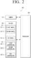
- FIG. 2 is a schematic configuration diagram of the robot 100 according to one or more embodiments of the disclosure.
- the robot 100 includes a camera 110, a driver 120, and a processor 130.
- the robot 100 may be divided into a head and a body.
- a head of the robot 100 may include the camera 110 or a sensor to perform a function of acquiring images of obj ects around the robot 100 or detecting the objects.
- the body of the robot 100 may be connected to the driver 120 to move the robot 100 or perform a function of a frame supporting the robot 100.
- the head may be connected to a rotatable motor and attached to the body.
- the robot 100 may acquire information on the objects around the robot 100 by rotating the head 360° without controlling the driver 120.
- the embodiments are not limited thereto, and the robot 100 may be implemented as an integrated body in which the head and body are not distinguished, and in this case, the body and the head may be distinguished on the robot 100 according to the functions performed.
- the camera 110 captures the objects around the robot 100 and acquires a plurality of images 10 of the obj ects. Specifically, the camera 110 may acquire the plurality of images 10 related to a getting on area 3 (e.g., an entrance area 3) and a getting off area 4 (e.g., an exit area 4) of the moving walkway 200 of the robot 100, and images of a fixed plate 210 and a plurality of movable plates 220 of the moving walkway 200. Also, the camera 110 may acquire images of objects (e.g., a person and/or an animal) existing in the getting off area 4.
- a getting on area 3 e.g., an entrance area 3
- a getting off area 4 e.g., an exit area 4
- the camera 110 may acquire images of objects (e.g., a person and/or an animal) existing in the getting off area 4.
- the camera 110 may be implemented as an imaging device such as a CMOS image sensor (CIS) having a CMOS structure, and/or a charge coupled device (CCD) having a CCD structure.
- CIS CMOS image sensor
- CCD charge coupled device
- the camera 110 is not limited thereto, and the camera 110 may be implemented as a camera 110 module of various resolutions capable of capturing a subject.
- the camera 110 may be implemented as a depth camera 110, a stereo camera 110, or an RGB camera 110. Accordingly, the camera 110 may acquire depth information of an object together with an image of the object.
- the driver 120 is a device capable of traveling the robot 100.
- the driver 120 may adjust the driving direction and the driving speed under the control of the processor 130.
- the driver 120 may include a power generating device (e.g., a gasoline engine, a diesel engine, a liquefied petroleum gas (LPG) engine, an electric motor depending on fuel (or energy source) used) that generates power for the robot 100 to drive, and a steering device (e.g., manual steering, hydraulics steering, and/or electronic control power steering (EPS)) for controlling a driving direction.
- a power generating device e.g., a gasoline engine, a diesel engine, a liquefied petroleum gas (LPG) engine, an electric motor depending on fuel (or energy source) used
- LPG liquefied petroleum gas
- EPS electronic control power steering
- the driver 120 operates a plurality of wheels 121 (first wheel 121, 121-1, second wheel 121, 121-2, ..., n-th wheel 121, 121-n, where n is a natural number greater than or equal to 2).
- the plurality of wheels 121 move the robot 100 by rotating based on the control of the processor 130.
- the driver 120 may drive the power generating device and rotate the plurality of wheels 121, based on the received electrical signal.
- the robot 100 may rotate by rotating at least one of the plurality of wheels 121 or by changing a rotation speed of the plurality of wheels 121.
- the driver 120 may drive the power generating device and rotate at least one of the plurality of wheels 121, based on the received electrical signal.
- the driver 120 may receive electrical signals of different magnitudes for each wheel and rotate each wheel at different speeds.
- the processor 130 generates a control signal related to rotation and stop of the plurality of wheels 121 of the driver 120, transmits an electrical signal corresponding to the generated control signal to the driver 120, and it will be described that the processor 130 controls to rotate or stop the plurality of wheels 121 of the driver 120.
- the driver 120 operates a plurality of suspensions 122 (first suspension 122-1, second suspension 122-2, ..., n-th suspension 122-n, where n is a natural number greater than or equal to 2).
- the suspension 122 is a component for alleviating or absorbing shock generated between the traveling robot 100 and the floor surface.
- the suspension 122 serves to connect each wheel to the robot 100 and the body. Accordingly, the suspension 122 may perform a function of mitigating shock generated between the robot 100 and the floor surface while the wheel 121 rotates to move the robot 100. To this end, the suspension 122 may be implemented as various suspension devices such as an air suspension 122 and a multi-link suspension 122.
- the suspension 122 may be compressed or tensioned under the control of the processor 130.
- the distance between the wheel 121 and the body of the robot 100 connected by the suspension 122 is reduced, and when the suspension 122 is tensioned, the distance between the wheel 121 and the body of the robot 100 connected by the suspension 122 may increase. Accordingly, the robot 100 may compress or tension the suspension 122 to change the posture of the robot.
- the processor 130 generates a control signal for tensioning or compressing the suspension 122 of the driver 120, transmits an electrical signal corresponding to the generated control signal to the driver 120, and it will be described that the processor 130 controls to tension or compress the suspension 122 of the driver 122.
- the robot 100 will be described as including four wheels 121 and four suspensions 122 connecting the four wheels 121 to the body of the robot 100. This is for convenience of description, and the robot 100 may be configured to have various numbers of wheels 121 and suspensions 122 according to one or more embodiments.
- the robot 100 may include at least one sensor.
- At least one sensor may be implemented as sensors (e.g., Lidar sensor and/or ToF sensor) used to detect objects around the robot 100 and sensors (e.g., IMU sensor) for detecting the posture of the robot.
- sensors e.g., Lidar sensor and/or ToF sensor
- sensors e.g., IMU sensor
- the processor 130 may control a general operation of the robot 100.
- the processor 130 may include, for example, a random access memory (RAM), a read only memory (ROM), a central processing unit (CPU), a graphic processing unit (GPU), and/or a system bus, and may execute calculations or data processing related to the control of one or more components included in the robot 100.
- RAM random access memory
- ROM read only memory
- CPU central processing unit
- GPU graphic processing unit
- system bus may execute calculations or data processing related to the control of one or more components included in the robot 100.
- the processor 130 may control one or more components included in the robot 100 by executing one or more instructions stored in a storage, control one or more components as a hardware circuit or chip, or control one or more components as a combination of software and hardware.
- the processor 130 may be electrically connected to various components in the robot 100 including the camera 110, the driver 120, at least one sensor (not illustrated), and the storage (not illustrated), and control these components.
- the processor 130 identifies the movement direction and movement speed of the moving walkway 200 based on the plurality of images 10 of the moving walkway 200 acquired through the camera 110.
- the processor 130 identifies that the robot 100 is located in the getting on area 3 of the moving walkway 200 based on map data of the travel space where the robot 100 is located.
- the map data is map data including information on a travel space set for the robot 100 to travel.
- the information on the travel space includes, for example, a traveling path of the robot 100 set in the travel space, location information such as a structure (e.g., moving walkway 200), a terrain, and/or an obstacle in the travel space.
- the map data may be stored in the memory of the robot 100 or may be received from an external server through a communication interface of the robot 100.
- the robot 100 may move within the travel space according to a predetermined traveling path based on the map data.
- the processor 130 may control the driver 120 so that the robot 100 moves to the moving walkway 200.
- the embodiments are not limited thereto, and the robot 100 may move in the travel space by tracking a user or an external electronic device communicating with the robot 100.
- the processor 130 may control the driver 120 to move the user or the external electronic device to the moving walkway 200.
- the processor 130 may identify that the robot 100 is located in the getting on area 3 of the moving walkway 200 based on the map data.
- the getting on area 3 means an area where a person or the robot 100 waits to get on the moving walkway 200.
- the getting on area 3 may include the fixed plate 210 installed at a boarding gate of the moving walkway 200.
- the fixed plate 210 means the fixed plate installed at the boarding gate and exit of the moving walkway 200.
- the fixed plate 210 may also be referred to as a landing plate.
- the fixed plate 210 is distinguished from the plurality of moving plates 220 forming the conveyor belt of the moving walkway 200.
- the moving plate 220 is disposed on an upper end of a roller of the moving walkway 200 and moves in a specific direction by a driver and a driving chain.
- the plate may also be referred to as, for example, a step, a footrest, and/or a stepping board.
- the getting off area 3 may further include a floor surface around the exit of the moving walkway 200.
- the getting on area 3 includes the fixed plate 210 installed at the boarding gate of the moving walkway 200, and may include a floor surface of a predetermined range around the fixed plate 210.
- Such getting on area 3 may be set on the map data in advance. Accordingly, the processor 130 may identify that the robot 100 is located in the getting on area 3 based on the map data.
- the processor 130 may identify that the robot 100 is located in the getting on area 3 by identifying a post beam installed on the fixing plate 210 of the getting on area 3. For example, when the post beam is recognized on an image acquired through the camera 110 while the robot 100 is traveling, the processor 130 may identify that the robot 100 is located in the getting on area 3. To this end, the processor 130 may use a neural network model trained to recognize the post beam.
- the neural network model may be a convolutional neural network (CNN) that includes a convolutional layer extracting feature information of an image and a fully-connected layer trained to identify an object included in the image based on the extracted feature information.
- CNN convolutional neural network
- the neural network model may be stored in memory.
- the processor 130 may perform communication with the post beam of the getting on area 3 through the communication interface of the robot 100 to identify the distance between the robot 100 and the post beam. In this case, when the identified distance is within a predetermined distance, the processor 130 may identify that the robot 100 is located in the getting on area 3.
- the processor 130 may identify that the robot 100 is located in the getting on area 3.
- the processor 130 may identify the moving plate 220 of the moving walkway 200 on an image acquired through the camera 110 while the robot 100 is traveling.
- the processor 130 may repeatedly acquire the image of the moving walkway 200 through the camera 110 as the robot 100 moves to the moving walkway 200.
- the processor 130 may identify that the moving area of the moving walkway 200 gradually expands on the image acquired through the camera 110.
- the moving area may be an area including the moving plate 220 of the moving walkway 200. Accordingly, as the robot 100 approaches the moving walkway 200, the processor 130 may identify that the moving area gradually expands on the image acquired in real time through the camera 110. The processor 130 may identify that the robot 100 is located in the getting on area 3 when the movement area is greater than or equal to a predetermined range.
- the robot 100 may identify whether the robot 100 is located in the getting on area 3 through the neural network model trained to identify the getting on area 3 on the image.
- the processor 130 may identify whether the robot 100 is located in the getting on area 3.
- the neural network model that detects the getting on area 3 included in the image may be implemented as, for example, a convolutional neural network (CNN) model, a fully convolutional networks (FCN) model, a regions with convolutional neuron networks features (RCNN) model, and/or a YOLO model.
- the neural network model may be stored in the memory.
- the processor 130 may identify that the robot 100 is located in the getting on area 3 by various methods.
- the processor 130 acquires the plurality of images 10 of the moving walkway 200 through the camera 110 when it is identified that the robot 100 is located in the getting on area 3.
- the processor 130 identifies the movement direction and movement speed of the moving walkway 200 based on the plurality of acquired images 10 of the moving walkway 200.
- the processor 130 may control the driver 120 to stop the robot 100.
- the processor 130 may acquire the plurality of images 10 of the moving walkway 200 through the camera 110 while the robot 100 is stopped.
- the processor 130 may control the driver 120 so that the robot 100 moves in order to acquire the plurality of images 10. Specifically, when it is detected that the robot 100 is located in the getting on area 3, the processor 130 may control the driver 120 to move the robot 100 to an image acquisition point in the getting on area 3.
- the image acquisition point may be a location set to acquire the image of the moving walkway 200 without interfering with the passage of a user or another robot 100 to get on the moving walkway 200.
- the image acquisition point may be set in advance for each getting on area on the map data.
- the processor 130 may acquire at least one image of the moving walkway 200 through the camera 110 when it is identified that the robot 100 is located in the getting on area, and identify the width of the moving walkway 200 through at least one acquired image.
- the width of the moving walkway 200 may be identified based on the detection of the moving plate 220 in at least one acquired image and the detected width of the moving plate 220.
- the processor 130 may select the image acquisition point of the robot 100 based on the identified width of the moving walkway 200.
- the driver 120 may be controlled so that the robot 100 is located on one side of the boarding gate of the moving walkway 200.
- the processor 130 may identify the movement direction and movement speed of the moving walkway 200 through the plurality of acquired images 10 of the moving walkway 200. Specifically, the processor 130 may detect the moving plate 220 within the plurality of acquired images 10 of the moving walkway 200. The processor 130 may identify the location of the moving plate 220 detected in each image and identify a change in the identified location of the moving plate 220. The processor 130 may identify the movement direction of the moving walkway 200 based on the change in the identified location of the moving plate 220, and may also identify the movement speed of the moving walkway 200 based on the change in the identified location of the moving plate 220 and a frame rate for the plurality of images 10.
- FIG. 3 is an exemplary diagram illustrating a method of identifying a movement direction and a movement speed of a moving walkway according to one or more embodiments of the disclosure.
- the processor 130 may acquire the plurality of images 11 and 12 of the moving walkway 200 in the getting on area 3 through the camera 110 when it is identified that the robot 100 is located in the getting on area 3. Specifically, the processor 130 may acquire a first image 11 of the moving walkway 200 at time t1 and acquire a second image 12 of the moving walkway 200 at time t2.
- the processor 130 may set a region of interest (ROI) 20 of the plurality of images 10 acquired through the camera 110. Specifically, the processor 130 may identify a variable region within the image by comparing the plurality of acquired images 10. Since the fixed plate 210 within the plurality of images 10 remains fixed and does not move, the variable region may be identified based on the movement of the moving plate 220 detected within the plurality of images 10. The processor 130 may set a region corresponding to the variable region as the region of interest.
- ROI region of interest
- the processor 130 may identify a change in location of at least one moving plate 220 within the set region of interest.
- the processor 130 may identify the change in locations of the first moving plate 221 and the second moving plate 222 in the first image 11 and the second image 12.
- the processor 130 may identify the movement direction and movement speed of the moving walkway 200 based on the change in locations of each of the moving plates 220 (first moving plate 221 and second moving plate 222) in the first image 11 and the second image 12, respectively. In this case, the processor 130 may identify that the movement direction of the moving walkway 200 is north.
- the processor 130 may set identifiers (e.g., plate ID) for each of the moving plates 220 detected in the plurality of images 10, and track each of the moving plates 220.
- identifiers e.g., plate ID
- the processor 130 may identify a boundary line between the plurality of plates of the moving walkway 200 based on the plurality of images 10 acquired through the camera 110 while the robot 100 is located in the getting on area 3, identify the movement direction of the moving walkway 200 based on the normal vector 40 of the identified boundary line, and identify the movement speed of the moving walkway 200 based on the movement speed of the identified boundary line.
- FIG. 4 is an exemplary diagram of a method of identifying a movement direction and a movement speed of a moving walkway based on a boundary line between plates according to one or more embodiments of the disclosure.
- the processor 130 may acquire the plurality of images 10 of the moving walkway 200 through the camera 110 while the robot 100 is located in the getting on area 3, and identify the boundary line between the plurality of adj acent moving plates 220 of the moving walkway 200 based on the plurality of acquired images 10.
- the processor 130 may extract linear components within each image by applying a linear detection algorithm to each of the plurality of images 10. For example, the processor 130 may extract linear components included in each image through Hough transformation.
- the extracted linear component may include the boundary between the fixed plate 210 and the moving plate 220, the boundary between the plurality of adjacent moving plates 220, a safety line marked on the moving plate 220, and a handrail of the moving walkway 200.
- the processor 130 may identify the boundary line corresponding to the boundary between the plurality of adjacent moving plates 220. Specifically, the processor 130 may identify the linear components within the ROIs 20 set in each image as the boundary line between the moving plates 220. Alternatively, the processor 130 may identify feature information of each linear component, and select the boundary lines between the plurality of moving plates 220 from among the plurality of linear components based on the identified feature information. Alternatively, the processor 130 may compare the plurality of images 10 to detect linear components whose locations are changed in each image, and identify the detected linear components as the boundary lines between the plurality of moving plates 220.
- the processor 130 may track the boundary line between the plurality of adjacent moving plates 220 identified in the plurality of images 10 and identify the movement directions and movement speed of the boundary line.
- the processor 130 may track the identified boundary line to identify the change in location of the boundary line in each image and identify the movement speed of the boundary line based on the identified change in location of the boundary line and the frame rate of each image.
- the processor 130 may detect the linear component included the ROI 20 set in a third image 13 acquired at time t3 and a fourth image 14 acquired at time t4, respectively.
- the plurality of linear components detected in the third image 13 and the fourth image 14 may include the boundary line between the fixed plate 210 and the moving plate 220, the boundary line between the handrail deck and the moving plate 200, and the boundary line between the plurality of adjacent moving plates 220.
- the processor 130 may identify the boundary lines between the plurality of moving plates 220 included in the ROI and track the identified boundary lines.
- the processor 130 may extract the normal vector 40 of the boundary line between the plurality of adj acent moving plates 220 and identify the movement direction of the moving walkway 200 based on the extracted normal vector 40. Specifically, the processor 130 may identify the normal vector 40 perpendicular to the boundary line between the moving plates 220. The processor 130 may identify the direction of the identified normal vector 40 as the direction in which the location of the moving plate 220 is changed. For example, the processor 130 may identify a coordinate value of a boundary line in a 2-dimensional (2D) coordinate space based on the location of the boundary line between the moving plates 220 in an image, and identify the normal vector 40 of the boundary line in the 2D coordinate space based on the identified coordinate value.
- 2D 2-dimensional
- the processor 130 may identify the boundary line 31 of the third moving plate 221 and the fourth moving plate 222 in the third image 13 acquired at time t3 and the fourth image 14 acquired at time t4, respectively, and may extract the normal vector 40 of the boundary line 31 in the fourth image. This may be identified based on the change in location of the boundary line 31 in the third image and the boundary line 31 in the fourth image.
- the processor 130 may identify the direction of the extracted normal vector 40 as the movement direction of the moving walkway 200.
- the processor 130 may select at least one plate to be used to identify the movement direction and movement speed of the moving walkway 200 from among the plurality of moving plates 220 detected in the plurality of images 10 acquired through the camera 110.
- the processor 130 may acquire distance information on the plurality of moving plates 220 detected in the plurality of images 10.
- the distance information on the moving plate 220 may be acquired through the camera 110 (e.g., a stereo camera 110 and/or an RGB camera 110) and/or a sensor (a Lidar sensor and/or a ToF sensor).
- the processor 130 may obtain 3D location information (e.g., coordinate values in a predetermined 3D coordinate space) of the plurality of moving plates 220 based on the obtained distance information.
- the processor 130 may detect the moving plate 220 having the lowest height (e.g., z-axis location) among the plurality of moving plates 220 based on the 3D location information of the plurality of moving plates 220.
- the processor 130 may identify the movement direction and movement speed of the moving walkway 200 based on the detected change in location of the moving plate 220.
- the processor 130 identifies the movement direction and movement speed of the moving walkway 200, and then controls the driver 120 so that the robot 100 faces a getting on direction (e.g., an entering direction) corresponding to the identified movement direction and controls the suspension 122 connected to at least one of the plurality of wheels 121 so that the robot 100 is tilted at an angle corresponding to the identified movement speed.
- the processor 130 may control the driver 120 so that the tilted robot 100 moves in the getting on direction and gets on the moving walkway 200.
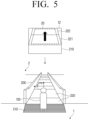
- FIG. 5 is an exemplary diagram illustrating determining the getting on direction of the robot based on the movement direction of the moving walkway according to one or more embodiments of the disclosure
- FIG. 6 is an exemplary diagram illustrating determining a tilt angle of the robot based on the movement speed of the moving walkway according to one or more embodiments of the disclosure.
- the processor 130 may identify the getting on direction of the robot 100 based on the identified movement direction of the moving walkway 200. For example, the processor 130 may identify the direction of the normal vector 40 of the boundary line between the moving plates 220 of the moving walkway 200 as the getting on direction of the robot 100. That is, the processor 130 may identify the movement direction of the moving walkway 200 as the getting on direction of the robot 100.
- the processor 130 may control the driver 120 so that the robot 100 faces the identified getting on direction. That is, the processor 130 may control the driver 120 of the robot 100 so that the vector that the body of the robot 100 faces matches the extracted normal vector 40. To this end, the processor 130 may generate the control information based on the movement direction of the moving walkway 200, and rotate the wheel 121 included in the driver 120 based on the generated control information to control the robot 100 to face the getting on direction. That is, the processor 130 may control the driver 120 to align the robot 100 in the movement direction of the moving walkway 200.
- the processor 130 identifies the movement direction of the moving walkway 200 as north.
- the processor 130 may identify the getting on direction of the moving walkway 200 of the robot 100 as north based on the movement direction of the moving walkway 200.
- the processor 130 may rotate the wheel so that the robot 100 faces north which is the getting on direction. Accordingly, the robot 100 facing the northeast direction may rotate in the north direction matching the movement direction of the moving walkway 200.
- the processor 130 may control the driver 120 so that the robot 100 faces the getting on direction, and then control the suspension 122 connected to at least one of the plurality of wheels 121 so that the robot 100 is tilted at an angle corresponding to the identified movement speed of the moving walkway 200.
- the processor 130 may control the driver 120 to identify an angle corresponding to the movement speed of the moving walkway 200 when the robot 100 is aligned toward the getting on direction.
- the processor 130 may identify the angle corresponding to the movement speed of the moving walkway 200 as a pitch angle of the robot 100. In this case, it may be identified in consideration of the angle corresponding to the movement speed of the moving walkway 200 is, for example, the movement speed of the moving walkway 200, a friction coefficient of the moving plate 220, a weight of the robot 100, and/or a weight of the object loaded on the robot 100.
- Equation 1 c ⁇ tan ⁇ 1 v mg
- ⁇ denotes an angle corresponding to the movement speed of the moving walkway 200
- v denotes the movement speed of the moving walkway 200
- m denotes a mass of the robot 100
- g denotes a gravitational acceleration
- c denotes a coefficient set in consideration of the, for example, friction coefficient of the moving plate 220.
- the processor 130 may control the suspension 122 connected to at least one of the plurality of wheels 121 so that the robot 100 is tilted at the angle corresponding to the movement speed of the moving walkway 200 which is identified based on the movement speed of the moving walkway 200. Specifically, the processor 130 may identify the lengths of the suspensions 122 of each of the plurality of wheels 121 so that the robot 100 is tilted at the angle corresponding to the movement speed of the moving walkway 200, and may identify at least one wheel for which the length of the suspension 122 should be changed from among the plurality of wheels 121. The processor 130 may generate control information so that the length of the suspension 122 of at least one identified wheel is adjusted, and may control the driver 120 based on the generated control information so that the robot 100 is tilted at the angle corresponding to the movement speed of the moving walkway 200.
- the processor 130 may control the suspension 122 connected to at least one of the plurality of wheels 121 to be tensioned, or the processor 130 may control the suspension 122 connected to at least one of the plurality of wheels 121 to be compressed, so the robot 100 may be tilted at the angle corresponding to the identified movement speed of the moving walkway 200.
- the processor 130 may control the suspension 122 connected to the third wheel 121 and the fourth wheel 121, respectively, located at the rear of the plurality of wheels 121 so that the robot 100 moves at an angle ⁇ 1 corresponding to an identified movement speed v1 of the moving walkway 200. Specifically, in FIG. 6 , the processor 130 tensions the suspension 122 connected to the third wheel 121 and the suspension 122 connected to the fourth wheel 121 so that the robot 100 is tilted.
- the processor 130 controls the driver 120 so that the tilted robot 100 moves in the getting on direction and gets on the moving walkway 200 after the robot 100 is tilted at the angle corresponding to the movement speed of the moving walkway 200.
- the processor 130 may control the driver 120 to move toward getting on direction while the robot 100 is tilted at the angle corresponding to the movement speed of the moving walkway 200.
- the processor 130 may determine the movement speed (that is, getting on speed) for the robot 100 to get on the moving walkway 200 based on the movement speed of the moving walkway 200.
- the processor 130 may determine the getting on speed of the moving walkway 200 as a speed increased by a predetermined ratio from the identified speed of the moving walkway 200.
- the processor 130 may identify the movement direction and movement speed of the moving walkway 200 on which the robot 100 intends to get, based on the image acquired through the camera 110 in the getting on area 3.
- the posture of the robot suitable for the identified movement direction and movement speed and the movement direction of the robot 100 are determined.
- the robot 100 may distinguish and identify the movement direction and movement speed of each of the moving walkways 200.
- the posture of the robot is not determined in consideration of the movement direction and movement speed of the moving walkway 200, and before the robot 100 gets on the moving walkway 200, since the getting on posture of the robot 100 is determined in consideration of the movement direction and movement speed of the moving walkway 200 in advance, it is possible to stably get the robot 100 on the moving walkway 200.
- the processor 130 may identify the width of the moving walkway 200 based on the plurality of images 10 acquired through the camera 110 while the robot 100 is located in the getting on area 3, determine a getting on location (e.g., an entrance location) of the moving walkway 200 of the robot 100 based on the identified width of the moving walkway 200, and control the driver 120 to face the getting on direction corresponding to the identified movement direction of the robot 100 at the determined getting on location.
- a getting on location e.g., an entrance location
- the processor 130 may identify the width of the moving walkway 200 based on the plurality of images 10 acquired through the camera 110 while the robot 100 is located in the getting on area 3.
- the processor 130 may identify the width of the moving walkway 200 based on the length information of the boundary line between the moving plates 220 detected in the image.
- the processor 130 may identify the width of the moving walkway 200 based on the width of the ROI set in the image.
- the processor 130 may determine the getting on location of the moving walkway 200 of the robot 100 based on the identified width of the moving walkway 200. For example, the processor 130 may determine the getting on location of the robot 100 as the center of the moving walkway 200 based on the width of the moving walkway 200. The processor 130 may control the driver 120 so that the robot 100 is located at the determined getting on location. In addition, the processor 130 may control the driver 120 so that the robot 100 faces the getting on direction corresponding to the identified movement direction of the robot 100 at the determined getting on position.
- the processor 130 may control the suspension 122 connected to at least one wheel so that the robot 100 is tilted at the angle corresponding to the movement speed of the moving walkway 200, and control the driver 120 so that the tilted robot 100 moves in the getting on direction from the determined getting on location and gets on the moving walkway 200.
- the processor 130 may identify the plurality of plates of the moving walkway 200 based on the plurality of images 10 of the moving walkway 200 acquired through the camera 110.
- the processor 130 may identify whether the robot 100 gets on the moving walkway 200. In this case, the processor 130 may identify that the robot 100 gets on the moving walkway 200 when it is identified that the location of the robot 100 is changed without the control of the driver 120 on the map data. Alternatively, when the processor 130 detects that the plurality of wheels 121 of the driver 120 are located on the moving walkway 200, the processor 130 may identify that the robot 100 gets on the moving walkway 200.
- the processor 130 may control the driver 120 so that the robot 100 stops, and acquire the plurality of images 10 of the moving walkway 20 through the camera 110 while the robot 100 stops.
- the processor 130 may control the suspension 122 of at least one of the plurality of wheels 121 so that the tilted robot 100 stands upright prior to acquiring the plurality of images 10 or while acquiring the plurality of images 10.
- the processor 130 may restore the tilted robot 100 to its original state based on the movement speed of the moving walkway 200.
- the original state of the robot 100 may be a state of the robot 100 before getting on the moving walkway 200 or a state in which the robot 100 is upright.
- the state in which the robot 100 stands upright may be the state in which the robot 100 is parallel to the floor surface where the moving walkway 200 is installed.
- the processor 130 may control the suspension 122 connected to the tensioned at least one wheel to be compressed based on the movement speed of the moving walkway 200, or control the suspension 122 connected to at least one compressed wheel to be tensioned based on the movement speed of the moving walkway 200, so that the robot 100 may be parallel to the floor surface on which the moving walkway 200 is installed.
- the processor 130 may align the robot 100 based on the identified getting on direction. For example, when the robot 100 gets on the moving walkway 200, by, for example, the frictional force generated between the moving walkway 200 (e.g., the moving plate 220 of the moving walkway 200) and the robot 100 (e.g., the wheel 121 of the robot 100), the direction of the robot 100, which matches the movement direction of the moving walkway 200, may be distorted when getting on.
- the moving walkway 200 e.g., the moving plate 220 of the moving walkway 200
- the robot 100 e.g., the wheel 121 of the robot 100
- the processor 130 may identify whether the robot 100 is aligned toward the movement direction of the moving walkway 200 immediately after the robot 100 gets on the moving walkway 200 based on the getting on direction identified before getting on. When it is identified that the robot 100 is not aligned toward the movement direction of the moving walkway 200, the processor 130 may control the wheel 121 of the driver 120 so that the robot 100 is aligned in the movement direction of the moving walkway 200 based on the getting on direction identified before getting on.
- the processor 130 may identify the plurality of plates of the moving walkway 200 within the plurality of acquired images 10.
- the plurality of plates identified in the plurality of images 10 acquired while the robot 100 is stationary on the moving walkway 200 may be the moving plate of the moving walkway 200 described above.
- the change in location of the moving plate 220 may not be identified in the plurality of images 10 acquired while the robot 100 gets on the moving walkway 200. This is because while the robot 100 gets on the moving robot 100, the robot 100 and the moving plate 220 move at the same movement speed. That is, the relative speed between and the moving plate 220 and the robot 100 on the moving walkway 200 has a value of '0'.
- the processor 130 may identify the plurality of moving plates 220 of the moving walkway 200 through the plurality of images 10 acquired through the camera 110.
- the plurality of moving plates 220 identified by the processor 130 through the plurality of images 10 may include the plurality of moving plates 220 located in front of the robot 100 and the moving plate below the robot 100 on which the robot 100 is standing.
- the processor 130 may identify the distance between the robot 100 and each of the moving plates 220 through the plurality of acquired images 10. For example, the processor 130 may identify the distances between the plurality of moving plates 220 and the robot 100, respectively, through the plurality of images 10 acquired by the camera 110 implemented as, for example, the depth camera 110 and/or the stereo camera 110. The processor 130 may identify the locations of each of the moving plates 220 with respect to the robot 100 based on the identified distance between each of the moving plates 220. For example, the processor 130 may identify the identified locations of each of the moving plates 220 in the 3D coordinate space 300.
- the processor 130 may identify the plurality of moving plates 220 using the sensor (e.g., Lidar sensor or ToF sensor) of the robot 100. For example, the processor 130 may identify a location where a laser emitted from the Lidar sensor is reflected after reaching objects around the robot 100 as a point. The processor 130 may identify a set of clustered points corresponding to each of the moving plates 220 among the identified plurality of points. In this case, the processor 130 may identify a set of clustered points corresponding to each of the moving plates 220 based on, for example, a random sample consensus (RANSAC) technique and/or a principal component analysis (PCA) technique.
- RNSAC random sample consensus
- PCA principal component analysis
- the processor 130 may identify the plurality of moving plates 220 around the robot 100, and identify the distance of each of the moving plates 220 from the robot 100 and the locations of each plate within the 3D coordinate space 300.
- the processor 130 may identify the plurality of moving plates 220 by combining the plurality of images 10 acquired through the camera 110 and the sensing information (point cloud about the plate) acquired through the sensor.
- the processor 130 may identify the plurality of plates within the plurality of images 10 acquired through the camera 110 by various methods, and identify locations of each of the plurality of identified plates.
- FIG. 7 is an exemplary diagram illustrating that the robot 100 getting on the moving walkway 200 identifies the plurality of plates according to one or more embodiments of the disclosure.
- the processor 130 may detect the plurality of moving plates 220 (i.e., a fifth moving plate 225, a sixth moving plate 226, and a seventh moving plate 227) on the image acquired through the camera 110.
- the processor 130 may identify the locations of each plate in the predetermined 3D coordinate space 300 based on the distance information of each plate acquired through the camera 110 or the sensor.
- the processor 130 may apply a Hough transform to each image in order to detect the plurality of moving plates 220 on each image, as in the getting on area described above, or set identifiers for the plurality of detected moving plates 220.
- the contents described with reference to the operation of the processor 130 in the getting on area may be equally applied.
- the processor 130 may identify the tilt angle of the moving walkway 200 based on the normal vector 40 of at least one of the plurality of identified moving plates 200.
- the processor 130 may extract the normal vectors 40 of the plurality of identified moving plates 220, respectively.
- the processor 130 may identify surfaces 225', 226', and 227' corresponding to each of the moving plates 220 based on the location information of each of the moving plates 220 identified in the 3D coordinate space 300.
- the coordinates of the surfaces 225', 226', and 227' corresponding to each of the moving plates may be identified by, for example, a matrix, a vector.
- the processor 130 may extract the normal vectors 40 to the surfaces 225', 226', and 227' corresponding to each of the moving plates.
- each normal vector 40 to the surfaces 225', 226', and 227' corresponding to each of the moving plates may be extracted in the same z-axis direction (e.g., +z-axis direction).
- the processor 130 may extract the normal vectors to the surfaces 225', 226', and 227' corresponding to each of the moving plates 220 based on, for example, a least square method. Referring back to FIG.
- the processor 130 may extract the normal vector 41 to the surface 225' corresponding to the fifth moving plate 225 on the 3D coordinate space 300 based on the location information of each of the moving plates, extract the normal vector 42 to the surface 226' corresponding to the sixth moving plate 226, and extract the normal vector 43 to the surface 227' corresponding to the seventh moving plate 227.
- the processor 130 may identify the tilt angle of the moving walkway 200 based on each of the normal vectors.
- the processor 130 may identify the location and direction of each normal vector 40 based on the posture of the robot and identify the tilt angle (specifically, the tilt angle between each moving plate and the floor surface where the moving walkway 200 is installed) formed by each of the moving plates.
- the processor 130 may identify the angle between the normal vector of the robot 100 and each of the moving plates in the 3D coordinate space 300, and identify the tilt angle formed by each of the moving plates based on the identified angle.
- FIG. 8 is an exemplary diagram of a method of identifying a tilt angle of a moving walkway 200 based on a normal vector of a plate according to one or more embodiments of the disclosure.
- the processor 130 may extract the normal vector 41 of the fifth moving plate 225, and identify the location and direction of the normal vector with respect to the robot 100 in the 3D coordinate space 300. Specifically, the processor may identify ⁇ 1 as the tilt angle of the fifth moving plate 225 based on the vector (i.e., the vector of the y component) in the direction that the robot body faces, a vector (i.e., the z-component vector) in the perpendicular direction of the header and body of the robot, and the normal vector 41 corresponding to the fifth moving plate 225. The processor 130 may extract the normal vector 42 corresponding to the sixth moving plate 226, and identify the location and direction of the normal vector 42 with respect to the robot 100 in the 3D coordinate space 300.
- the vector i.e., the vector of the y component
- a vector i.e., the z-component vector
- ⁇ 2 which is the tilt angle of the sixth moving plate 226, may be identified.
- the processor 130 may identify ⁇ 3, which is the tilt angle of the seventh moving plate 227, based on the normal vector 43 of the seventh moving plate 227.
- FIG. 9 is an exemplary diagram of a method of controlling a suspension of at least one wheel of a robot based on an identified tilt angle according to one or more embodiments of the disclosure.
- the processor 130 may control the suspension 122 of at least one wheel so that the robot 100 stands upright based on the identified tilt angle. That is, the suspension 122 of at least one wheel may be controlled so that the robot 100 is parallel to the floor surface on which the moving walkway 200 is installed.
- the processor 130 may identify rotation angles (roll angle and pitch angle) of the robot 100 based on the identified tilt angle.
- the processor 130 may tension or compress the suspension 122 of at least one wheel so that the robot 100 rotates based on the identified rotation angle of the robot 100.
- the processor 130 may identify the tilt angles of the plurality of moving plates 220 located in front of the robot 100, respectively, and then identify the time when the moving plate 220 on which the robot 100 is standing moves to the location of the moving plate 220 located in the front.
- the eighth moving plate 228 on which the robot 100 is standing moves to a point, where the fifth moving plate 225 is located at time t1, at time t2.
- the processor 130 may predict the tilt angle of the eighth moving plate 228 where the robot 100 is located at time t2 based on the tilt angle of the fifth moving plate 225 identified based on the image acquired at time t1.
- the processor 130 may control, based on the identified tilt angle, the suspension 122 of at least one wheel so that the robot 100 is parallel to the floor surface on which the moving walkway 200 is installed. For example, in FIG. 9 , based on the identified tilt angle ⁇ 1, the processor 130 may tension suspensions (i.e., the third suspension 122-3 and the fourth suspension 122-4) connected to the third and fourth wheels 121-3 and 121-4 of the robot 100, respectively.
- the processor 130 may generate the control information on each of the third suspension 122-3 and the fourth suspension 122-4 so that the lengths of the third suspension 122-3 and the fourth suspension 122-4 are increased by l2, and tension each of the third suspension 122-3 and the fourth suspension 122-4 based on the generated control information.
- the robot 100 may be parallel to the floor surface on which the moving walkway 200 is installed at time t2.
- the processor 130 may adjust a yaw angle along with a pitch angle of the robot 100 based on the tilt angle of each moving plate 220.
- the time when the processor 130 controls, based on the identified tilt angle, the suspension 122 of at least one wheel so that the robot 100 is parallel to the floor surface on which the moving walkway 200 is installed may be set based on the movement speed of the moving walkway 200 and the length information of the moving plate 220. That is, referring to FIG. 9 again, the processor 130 may determine based on the movement speed v of the moving walkway 200 and the length information l of the moving plate 220 that the eighth moving plate 228 where the robot 100 is located at time t1 is located at d2 (i.e., the location of the fifth moving plate 225 at time 11) at time t2.
- the processor 130 may control the suspension 122 of at least one wheel based on the tilt angle of the fifth moving plate 225 identified at time t1 just before time t2 arrives (e.g., before a predetermined time from time t2). Accordingly, even if the eighth moving plate 228 on which the robot 100 is standing moves at d2, the robot 100 may be parallel to the floor surface as in d1.
- the processor 130 may determine that the eighth moving plate 228 on which the robot 100 is located at time (e.g., time t3) after time t2 is located at d3 (i.e., location of the sixth moving plate at time 11).
- the length information l of the moving plate 220 may be identified based on, for example, the distance information on the moving plate 220 acquired through the camera 110 and/or the point cloud of the moving plate 220 acquired through the sensor.
- the processor 130 may control the suspension 122 of at least one wheel of the robot 100 based on the tilt angle of the sixth moving plate identified at time t1. For example, the processor 130 may identify the difference between the tilt angle of the fifth movement plate 225 identified at time t1 and the tilt angle of the sixth movement plate 226 based on the normal vector of the fifth movement plate 225 and the normal vector of the sixth movement plate. The processor 130 may generate, based on the difference in the identified tilt angle, the control information for the suspension 122 connected to at least one wheel so that the robot 100 at time t3 based on the posture of the robot at time t2 is parallel to the floor surface on which the moving walkway 200 is installed. The processor 130 may adjust the posture of the robot 100 so that the robot 100 is parallel to the floor surface at time t3 based on the generated control information (e.g., tension or compression length information of the suspension 122 connected to at least one wheel).
- the generated control information e.g., tension or compression length information of the suspension 122 connected to at least one wheel.
- the processor 130 may reextract the normal vector of the fifth moving plate 225 located at d3 through the plurality of images 10 acquired at time t2, and may identify the location and direction of the normal vector of the fifth moving plate 225 based on the posture (i.e., the horizontal posture of the robot 100 relative to the floor surface) of the robot at time t2 within the 3D coordinate space 300.
- the processor 130 may identify the tilt angle of the fifth moving plate 225 at time t2. In this case, the processor 130 may identify a relative angle difference between the eighth moving plate 228 and the fifth moving plate 225 where the robot 100 is located at time t2. The processor 130 may control the suspension 122 connected to at least one wheel so that the robot 100 is parallel to the floor surface on which the moving walkway 200 is installed, based on the identified relative angle difference or the tilt angle of the fifth moving plate 225.
- the processor 130 may again identify the plurality of moving plates 220 of the moving walkway 200 based on the image acquired through the camera 110 even after controlling the suspension 122 of at least one wheel so that the robot 100 is parallel to the floor surface on which the moving walkway 200 is installed based on the identified tilt angle, and continuously identify the tilt angle of the moving walkway 200 based on the normal vector of at least one of the identified plurality of plates 220. Accordingly, even if the tilt angle of the moving plate 220 on which the robot 100 is located is changed, the processor 130 may predict the tilt angle of the moving plate 220 in advance and control the posture of the robot to be level with the floor surface.
- the processor 130 may control the suspension 122 connected to at least one wheel based on the identified tilt angle while the robot 100 gets on the moving walkway 200, and may rotate at least one wheel to adjust the direction of the robot 100. Specifically, the processor 130 may identify the boundary line between the plurality of moving plates 220 based on the image of the moving walkway 200 acquired through the camera 110.
- the processor 130 may detect a boundary line between the plurality of moving plates 220 of the moving walkway 200 through a straight line detection algorithm (e.g., Hough transform).
- the processor 130 may extract the normal vector of the detected boundary line and continuously identify the movement direction of the moving walkway 200 based on the extracted normal vector.
- the processor 130 may control the driver 120 to rotate at least one wheel so that the posture of the robot faces the movement direction of the moving walkway 200.
- the processor 130 may select at least one of the plurality of moving plates 220 detected on the image acquired through the camera 110 based on the movement speed of the moving walkway 200.
- the processor 130 may extract the normal vectors only to at least one selected plate.
- at least one selected plate will be referred to as a target plate.
- the processor 130 may select only the fifth and sixth moving plates 225 and 226 among the plurality of moving plates 220 (fifth to seventh moving plates 225 to 227) as the target plate, and extract only the normal vectors to the fifth and sixth moving plates 225 and 226.
- the processor 130 may select the moving plate (i.e., a target plate) from which the normal vector 40 is extracted from among the plurality of moving plates 220 detected through the plurality of images 10, thereby preventing unnecessary waste of resources of the robot 100.
- the target plate may be selected based on the movement speed of the moving walkway 200. That is, when the movement speed of the moving walkway 200 is slow, a small number of target plates may be selected, and when the movement speed of the moving walkway 200 is fast, a large number of target plates may be selected. As the movement speed of the moving walkway 200 increases, the tilt angle of the moving plate 220 on which the robot 100 stands may also change rapidly. Therefore, the reason why the processor 130 predicts the tilt angle of the moving plate 220 far from the robot 100 is that the robot 100 may take a more stable posture in the moving walkway 200.
- the processor 130 may identify at least one of the plurality of plates based on the movement speed of the moving walkway 200 and the response speed of the suspension 122.
- the processor 130 may select the target plate based on the movement speed of the moving walkway 200 and the response speed of the suspension 122 among the plurality of moving plates 220 detected on the plurality of images 10 acquired through the camera 110. For example, referring to FIG. 9 , when the response speed of the suspension 122 is slower than the movement speed of the moving walkway 200, the processor 130 may set the sixth movement plate 226 of the plurality of moving plates 220 (fifth to seventh moving plates 225 to 227) identified at time t1 as the target plate. Alternatively, when the response speed of the suspension 122 is faster than the movement speed of the moving walkway 200, the processor 130 may set all the plurality of moving plates 220 (fifth to seventh moving plates 225 to 227) identified at time t1 as the target plate.
- the processor 130 may compare the identified movement speed of the moving walkway 200 and the response speed of the suspension 122 and flexibly set the target plate based on the comparison result. Accordingly, the processor 130 may appropriately change the posture of the robot according to the movement speed of the moving walkway 200.
- the processor 130 may control the suspension 122 of at least one wheel so that the robot 100 stands upright based on the sensing value acquired through the sensor of the robot 100.
- the sensor of the robot 100 may include an inertial measurement unit (IMU) sensor.
- the moving plate 220 may not be included in the image obtained through the camera 110.
- the processor 130 may not identify the tilt angle of the moving walkway 200. Therefore, the processor 130 may identify the tilt angle of the moving walkway 200 through the IMU sensor when the moving plate 220 of the moving walkway 200 is not detected on the plurality of images 10 acquired through the camera 110 while the robot 100 gets on the moving walkway 200 or the detected moving walkway 200 is less than the predetermined number.
- the IMU sensor is a sensor composed of an accelerometer and a gyroscope, and may sense the posture of the robot and calculate the angle formed by the posture of the robot.
- the angle formed by the posture of the robot may correspond to the tilt angle of the moving walkway 200. Therefore, the processor 130 may identify an angle for the robot 100 to stand upright (or for the robot 100 to be level with the floor surface) based on the sensing information (i.e., the angle of the posture of the robot) acquired based on the IMU sensor.
- the processor 130 may control the robot 100 to stand upright by extending or compressing the suspension 122 connected to at least one wheel based on the identified angle.
- the suspension 122 of at least one wheel may be controlled based on the sensing value acquired through the IMU sensor so that the robot 100 stands upright.
- the processor 130 may identify the tilt angle of the moving walkway 200 based on the normal vectors of the plurality of moving plates 220 identified through the plurality of images 10, and use the IMU sensor even when the suspension 122 connected to at least one wheel is controlled based on the identified tilt angle of the moving walkway 200. Specifically, the processor 130 may control the suspension 122 connected to at least one wheel so that the robot 100 stands upright based on the normal vector of the moving plate 220 located in front of the robot 100, and then verify whether the robot 100 correctly stands upright based on the sensing value acquired through the IMU sensor. When it is identified that the robot 100 does not exactly stand upright based on the sensing value acquired through the IMU sensor, the processor 130 may identify a compensation value for the suspension 122 with the acquired sensing value. Based on the identified compensation value, the processor 130 may control the suspension 122 connected to at least one wheel again.
- the processor 130 identifies the movement direction of the moving walkway 200 based on the acquired plurality of images 10, controls the driver 120 so that the robot 100 faces the getting off direction corresponding to the identified movement direction, and controls the driver 120 so that the upright robot 100 moves in the getting off direction and gets off the moving walkway 200.
- the processor 130 may first identify the getting off area 4 and identify the distance between the identified getting off area 4 and the robot 100.
- the getting off area 4 refers to an area where a person or robot 100 getting on the moving walkway 200 lands after getting off the moving plate 220 of the moving walkway 200.
- the getting off area 4 may include the fixed plate 210 installed at the exit of the moving walkway 200.
- the getting off area 4 may further include the floor surface around the boarding gate of the moving walkway 200.
- the getting on area 3 includes the fixed plate 210 installed at the boarding gate of the moving walkway 200, and may include a floor surface of a predetermined range around the fixed plate 210.
- the processor 130 may identify the getting off area 4 based on the map data. Specifically, the getting off area 4 of each moving walkway 200 may be set on the map data in advance. Accordingly, the processor 130 may identify the location of the getting off area 4 based on the map data. The processor 130 may identify the real-time location of the robot 100 on the map data and identify the distance between the robot 100 and the getting off area 4 of the moving walkway 200 on which the robot 100 gets. When the distance between the position of the robot 100 on the map data and the location of the getting off area 4 of the moving walkway 200 on which the robot 100 gets is within the predetermined distance, the processor 130 may identify that the robot 100 is located within the predetermined distance from the getting off area 4 of the moving walkway 200.
- the processor 130 may identify the fixed plate 210 on the image acquired through the camera 110 while the robot 100 is traveling, and identify the distance between the getting off area 4 and the robot 100 based on the identified fixed plate 210.
- the processor 130 may identify an area including the detected fixed plate 210 as the getting off area 4, and identify the distance between the identified getting off area 4 and the robot 100.
- FIG. 10 is a diagram for describing identification of a getting off area and a distance between the getting off area and the robot based on an image acquired through a camera, according to one or more embodiments of the disclosure.
- the fixed plate 210 is not detected in an image 13 acquired at time t6, whereas the fixed plate 210 is detected in images 14 and 15 acquired at time t7 and t8.
- the processor 130 may identify the distance between the detected fixed plate 210 and the robot 100.
- the distance between the fixed plate 210 and the robot 100 may be identified based on the depth value of the fixed plate 210 included in the image acquired through the camera 110 (e.g., the depth camera 110 and/or the stereo camera 110) or the sensing value for the distance between the robot 100 and the fixed plate 210 acquired through the sensor.
- the processor 130 may identify that the robot 100 is located within the predetermined distance from the getting off area 4.
- the processor 130 may identify that the area of the fixed plate 210 of the moving walkway 200 on the image 10 acquired through the camera 110 gradually expands. Accordingly, as the robot 100 approaches the getting off area 4 of the moving walkway 200, the processor 130 may identify that the area of the fixed plate 210 gradually expands on the image acquired in real time through the camera 110.
- the processor 130 may identify the area whose location and size are changed within the plurality of images 10 acquired through the camera 110 as the getting off area 4. Accordingly, the processor 130 may identify that the robot 100 is located within the predetermined distance from the getting off area 4 when the area of the fixed plate 210 is greater than the predetermined range.
- the processor 130 may identify the number of the plurality of moving plates 220 identified through the image 10 acquired while the robot 100 gets on the moving walkway 200, and may identify that the robot 100 is located within a predetermined distance from the getting off area 4 based on the number of identified moving plates 220. Specifically, when the number of identified moving plates 220 is changed or the number of identified moving plates 220 is less than the predetermined number, the processor 130 may identify that robot 100 is located within the predetermined distance from the getting off area 4.
- the number of moving plates 220 detected in the image 13 acquired at time t6 is three
- the number of moving plates 220 detected in the image 14 acquired at time t7 is two
- the number of moving plates 220 detected in the image 150 acquired at time t8 is one.
- the processor 130 may identify that the robot 100 is located within the predetermined distance from the getting off area 4 at time t8.
- the robot 100 may identify the getting off area 4 on the image 10 through the neural network model trained to identify the getting off area 4.
- the processor 130 may identify the getting off area 4 of the moving walkway 200.
- the neural network model that detects the getting off area 4 included in the image may be implemented as, for example, a convolutional neural network (CNN) model, a fully convolutional networks (FCN) model, a regions with convolutional neuron networks features (RCNN) model and/or a YOLO model.
- the neural network model may be stored in the memory.
- the processor 130 may identify that the robot 100 is within the predetermined distance from the getting off area 4 of the moving walkway 200 when the tilt angle of the identified moving walkway 200 is within the predetermined angle.
- the tilt angle may be the minimum in the getting off area 4 of the moving walkway 200.
- the tilt angle may be 0° so as to be parallel to the moving walkway 200 and the floor surface on which the moving walkway 200 is installed.
- the tilt angle of the identified moving walkway 200 may also decrease. Therefore, the processor 130 may identify the tilt angle of the moving walkway 200 in real time based on the normal vector of the moving plate 220 located in front of the robot 100, and when the identified tilt angle is within the predetermined angle, the processor 130 may identify that the robot 100 is within the predetermined distance from the getting off area 4 of the moving walkway 200.
- the processor 130 may identify that the robot 100 is located in the getting on area 3 by identifying the post beam installed on the fixing plate 210 of the getting on area 3. For example, when the post beam is recognized on the image acquired through the camera 110 while the robot 100 gets on the moving walkway 200, the processor 130 may identify that there is the getting off area 4 in front of the robot 100. To this end, the processor 130 may use the neural network model trained to recognize the post beam of the getting off area 4.
- the neural network model may be a convolutional neural network (CNN) that includes a convolutional layer extracting feature information of an image and a fully-connected layer trained to identify an object included in the image based on the extracted feature information.
- CNN convolutional neural network
- the neural network model may be stored in memory.
- the processor 130 may perform communication with the post beam of the getting on area 4 through the communication interface of the robot 100 to identify the distance between the robot 100 and the post beam. In this case, when the identified distance is within a predetermined distance, the processor 130 may identify that the robot 100 is located in the getting on area 3.
- the processor 130 may identify the getting off area 4 and identify the distance between the identified getting off area 4 and the robot 100 by various methods.
- the processor 130 may identify the movement direction of the moving walkway 200 based on the acquired plurality of images 10 when it is identified that the robot 100 is within the predetermined distance from getting off area 4, and control the driver 120 so that the robot 100 faces the getting off direction corresponding to the identified movement direction.
- the processor 130 may control the driver 120 so that the robot 100 maintaining the upright state moves to the getting off direction and gets off the moving walkway 200.
- the processor 130 may set the ROI 20 including the moving plate 220 of the moving walkway 200 on the plurality of images 10 acquired through the camera 110, and identify the change in location of the moving plate 220 within the ROI 20.
- the movement direction of the moving walkway 200 in the getting off area 4 may be identified based on the identified change in location of the moving plate 220.
- the processor 130 may identify the boundary line between the plurality of moving plates 220 using the straight line detection algorithm, extracts the normal vector 40 perpendicular to the identified boundary line, and identify the movement direction of the moving walkway 200 in the getting off area 4.
- the method of identifying the movement direction of the moving walkway 200 in the getting off area 4 based on the plurality of acquired images 10 may be equally applied. Therefore, a detailed description thereof will be omitted.
- the processor 130 may control the driver 120 so that the robot 100 faces the getting off direction corresponding to the identified movement direction. Specifically, the processor 130 may generate the control information based on the movement direction of the moving walkway 200 in the getting off area 4, and rotate the wheel 121 included in the driver 120 based on the generated control information to control the robot 100 so the robot 100 faces the getting on direction. That is, the processor 130 may control the driver 120 to align the robot 100 in the movement direction of the moving walkway 200.
- the processor 130 may control the driver 120 so that the upright robot 100 moves to the getting off direction and gets off the moving walkway 200. Specifically, the processor 130 may identify whether the robot 100 is parallel to the floor surface. In this case, as the tilt angle of the moving walkway 200 decreases in the getting off area 4, the robot 100 within the predetermined distance from the getting off area 4 may be parallel to the floor surface.
- the processor 130 may verify the posture of the robot through the IMU sensor. That is, it is identified based on the sensing value obtained through the IMU sensor whether the robot 100 is upright (or parallel to the floor surface), and when the robot 100 does not stand upright (or when it is identified that the robot is not parallel to the floor surface), it is possible to control the suspension 122 connected to at least one wheel based on the sensing value acquired through the IMU sensor. When it is identified that the robot 100 stands upright (or when it is identified that the robot 100 is parallel to the floor surface), the processor 130 may control the driver 120 so that the robot 100 moves to the identified getting off direction and gets off the moving walkway 200.
- the movement speed of the robot 100 for getting off the moving walkway 200 may be set based on the movement speed of the moving walkway 200. That is, the processor 130 may set the getting off speed at a speed higher than the movement speed of the moving walkway 200 by a predetermined ratio. The processor 130 may control the driver 120 to move the robot 100 to the identified getting off direction at the set getting off speed.
- the processor 130 may identify the movement speed of the moving walkway 200 in the getting off area 4. Specifically, the processor 130 sets the ROI 20 including the moving plate 220 of the moving walkway 200 on the plurality of images 10 acquired through the camera 110, and identify a movement speed of the moving walkway 200 based on the change in location of the moving plate 220 in the ROI 20 and the frame rate of the plurality of images 10.
- the processor 130 may identify the boundary line between the plurality of movable plates 220 using the straight line detection algorithm, and track the identified boundary line to identify the change in location of the boundary line.
- the method of identifying, by the processor 130, the movement speed of the moving walkway 200 in the getting off area 4 based on the plurality of acquired images 10 the method of identifying the movement speed of the moving walkway 200 in the getting on area 3 may be equally applied. Therefore, a detailed description thereof will be omitted.
- the processor 130 may control the suspension 122 connected to at least one of the plurality of wheels 121 so that the robot 100 is inclined at an angle corresponding to the movement speed of the moving walkway 200 in the getting off area 4, and control the driver 120 so that the tilted robot 100 moves to the getting off direction and gets off the moving walkway 200.
- the processor 130 may tension or compress the suspension 122 connected to at least one wheel so that the robot 100 tilts in the opposite direction to the getting off direction by considering the frictional force in the getting off area 4.
- the processor 130 may tension the suspension (i.e., the first suspension 122-1 and the second suspension 122-2) connected to the wheel 121 (i.e., the first wheel 121-1 and the second wheel 121-2) located on the getting off direction side of the robot 100 to control the robot 100 so that the robot 100 is tilted in a direction opposite to the getting off direction.
- the suspension i.e., the first suspension 122-1 and the second suspension 122-2
- the wheel 121 i.e., the first wheel 121-1 and the second wheel 121-2
- the method of identifying the angle at which the robot 100 is tilted based on the movement speed of the moving walkway 200 in the getting on area 3 and the method of controlling the suspension 122 connected to at least one wheel to control the robot 100 to be tilted may be equally applied, and therefore, a detailed description thereof will be omitted.
- the processor 130 may identify the posture of the robot 100 as an upright posture or a tilted posture according to the driving mode of the robot 100 in the getting off area 4. For example, when the robot 100 stops in the getting off area 4 after getting off the moving walkway 200, the suspension 122 connected to at least one wheel may be controlled to tilt the posture of the robot at the angle corresponding to the movement speed of the moving walkway 200. However, when the robot 100 moves in the getting off area 4 after getting off the moving walkway 200, the suspension 122 connected to at least one wheel may be controlled so that the robot 100 stands upright.
- the processor 130 may control the driver 120 so that the robot 100 moves in the direction opposite to the getting off direction.
- the processor 130 may identify whether an object 410 exists in the getting off area 4 based on the image acquired through the camera 110. That is, when the getting off area 4 and the object 410 on the getting off area 4 are detected in the acquired image, the processor 130 may identify that the object 410 exists in the getting off area 4. Alternatively, the processor 130 may identify whether the object 410 exists in the getting off area 4 located in front of the robot 100 through the sensor (e.g., Lidar sensor and/or ToF sensor).
- the sensor e.g., Lidar sensor and/or ToF sensor
- the processor 130 identifies the distance between the object 410 present in the getting off area 4 and the robot 100.
- the processor 130 may control the plurality of wheels 121 of the driver 120 so that the robot 100 moves in the opposite direction to the identified getting off direction.
- the processor 130 may control the plurality of wheels 1210 to rotate in the direction opposite to the movement direction of the moving walkway 200.
- the processor 130 may control the driver 120 so that the robot 100 moves toward the opposite direction to the getting off direction at the same speed as the movement speed of the moving walkway 200 in the identified getting off area 4. Accordingly, the robot 100 may maintain its position on the moving walkway 200. This may exert the same effect as if a person walks in place in the moving walkway 200.
- the processor 130 may control the driver 120 so that the robot 100 moves in the getting off direction and gets off the moving walkway 200.
- FIG. 11 is a diagram for explaining controlling the driver 120 so that the robot 100 moves in the direction opposite to the getting off direction when the object exists in the getting off area, according to one or more embodiments of the disclosure.
- the processor 130 may detect that a person 410 exists in the getting off area 4. In this case, the processor 130 may control the driver 120 so that the robot 100 moves in the direction opposite to the getting off direction at the same speed v as the movement speed v of the moving walkway 200 in the getting off area 4. In this way, the robot 100 may maintain its position on the moving walkway 200 until the person 410 existing in the getting off area 4 disappears. Accordingly, it is possible to avoid a collision with the person 410 existing in the getting off area 4 while staying on the moving walkway 200.
- the processor 130 While the processor 130 controls the driver 120 by identifying that the object exists in the getting off area 4 to move the robot 100 to the opposite direction to the getting off direction, the processor 130 may identify whether another object 420 exists behind the robot 100.
- the processor 130 may rotate the image acquired through the camera 110 provided at the rear of the robot 100 or the sensor provided at the rear or the sensor provided at the robot 100 to identify another object 420 located behind the robot 100.
- the processor 130 may identify the distance between another object 420 located behind the robot 100 and the robot 100.
- the processor 130 may transmit a signal requesting to stop the moving walkway 200 to the server controlling the moving walkway 200 through the communication interface of the robot 100.
- the processor 130 may directly transmit a control signal to stop the operation of the moving walkway 200 to the moving walkway 200 through the communication interface.
- FIG. 12 is a detailed configuration diagram of a robot according to one or more embodiments of the disclosure.
- the robot 100 includes the camera 110, the driver 120, the display 140, the sensor 150, the memory 160, the speaker 170, the user interface 180, and the communication interface 190.
- a detailed description for components overlapped with components illustrated in FIG. 2 among components illustrated in FIG. 12 will be omitted.
- the display 140 may display various types of visual information.
- the display 140 may display information on the map data, the traveling path of the robot 100, and/or the movement direction and movement speed of the escalator 200.
- the display 140 may be implemented as a display including a self-light emitting element or a display including a non-light emitting element and a backlight.
- the display 140 may be implemented as various types of displays such as a liquid crystal display (LCD), an organic light emitting diodes (OLED) display, light emitting diodes (LED), a micro LED, a Mini LED, a plasma display panel (PD), a quantum dot (QD) display, and quantum dot lightemitting diodes (QLED).
- a driving circuit and/or a backlight unit that may be implemented in a form such as a-si TFT, low temperature poly silicon (LTPS) TFT, and/or an organic TFT (OTFT), may be included in the display 140.
- the display 140 may be implemented as, for example, a touch screen coupled with a touch sensor, a flexible display, a rollable display, a 3D display, and/or a display to which a plurality of display modules are physically connected.
- the display 140 may be implemented as a touch screen together with the touch panel.
- the display unit 140 may function as an output unit for outputting the information between the robot 100 and the user, and at the same time, function as an input unit for providing an input interface between the robot 100 and the user.
- the memory 150 may store data.
- the map data about the travel space where the robot 100 is located may be stored in the memory 150.
- the memory 150 may be implemented in a form of a memory embedded in the robot 100 or a form of a memory detachable from the robot 100, depending on a data storage purpose.
- data for driving the robot 100 may be stored in the memory embedded in the robot 100
- data for an extension function of the robot 100 may be stored in the memory attachable to and detachable from the robot 100.
- the memory embedded in the robot 100 may include at least one of, for example, a volatile memory (for example, a dynamic random access memory (DRAM), a static RAM (SRAM), and/or a synchronous dynamic RAM (SDRAM)), a non-volatile memory (for example, a one-time programmable read only memory (OTPROM), a programmable ROM (PROM), an erasable and programmable ROM (EPROM), an electrically erasable and programmable ROM (EEPROM), a mask ROM, and/or a flash ROM), a flash memory (for example, a NAND flash, and/or a NOR flash), a hard drive, and a solid state drive (SSD)).
- a volatile memory for example, a dynamic random access memory (DRAM), a static RAM (SRAM), and/or a synchronous dynamic RAM (SDRAM)
- a non-volatile memory for example, a one-time programmable read only memory (OTPROM), a
- the memory 300 detachable from the robot 100 may be implemented in the form of the memory card (e.g., compact flash (CF), secure digital (SD), micro secure digital (Micro-SD), mini secure digital (Mini-SD), extreme digital (xD), multi-media card (MMC)), and/or external memory (e.g., USB memory) connectable to a USB port.
- the memory card e.g., compact flash (CF), secure digital (SD), micro secure digital (Micro-SD), mini secure digital (Mini-SD), extreme digital (xD), multi-media card (MMC)
- external memory e.g., USB memory
- the memory 150 may store information on a plurality of neural networks (or, artificial intelligence) models.
- the memory 150 may store a neural network model trained to identify the getting on area on the image acquired through the camera 110 and a neural network trained to identify the getting off area 4 on an image acquired through the camera 110.
- Storing the information on the neural network model may mean storing various types of information related to the operation of the neural network model, for example, information on at least one layer included in the neural network model, information on parameters and/or bias used in each of the at least one layers.
- the information on the neural network model may be stored in the internal memory of the processor 130 according to the implementation form of the processor 130.
- the processor 130 is implemented as dedicated hardware, the information on the neural network model may be stored in the internal memory of the processor 130.
- the robot 100 includes at least one sensor 160.
- At least one sensor 160 may further include at least one of a gesture sensor, a gyro sensor, a barometric pressure sensor, a magnetic sensor, an acceleration sensor, a grip sensor, a proximity sensor, a color sensor (e.g., a red, green, blue (RGB) sensor), a bio sensor, a temperature/humidity sensor, an illuminance sensor, and an ultra violet (UV) sensor in addition to sensors (e.g., Lidar sensor and/or ToF sensor) for detecting objects around the robot 100 and sensors (e.g., IMU sensor) for detecting a posture of a robot described above.
- sensors e.g., Lidar sensor and/or ToF sensor
- sensors e.g., IMU sensor
- the speaker 170 may output a sound signal to the outside of the robot 100.
- the speaker 170 may output, for example, multimedia reproduction, recording reproduction, various kinds of notification sounds, and/or voice messages.
- the robot 100 may include an audio output device such as a speaker 170, or may include an output device such as an audio output terminal.
- the speaker 170 may provide, for example, acquired information, information processed/produced based on the acquired information, a response result to a user's voice, and/or an operation result in the form of voice.
- the processor 130 may output a warning sound through the speaker 170 when it is identified that the robot 100 is located within the getting off area 4 of the moving walkway 200 and the predetermined distance and an object exists in the getting off area 4.
- the user interface 180 is a component used for the robot 100 to interact with a user, and the processor 130 may receive various types of information, such as the control information of the robot 100, the travel space information (e.g., map data for the travel space) where the robot 100 is located, and the information on the moving walkway 200, through the user interface 180.
- the user interface 180 may include at least one of a touch sensor, a motion sensor, a button, a jog dial, a switch, or a microphone, but is not limited thereto.
- the communication interface 190 may transmit and receive various types of content.
- the communication interface 190 may receive or transmit signals from or to an external device (e.g., user terminal), an external storage medium (e.g., USB memory), and/or an external server (e.g., web hard), in a streaming or download method through communication methods such as AP-based Wi-Fi (wireless LAN network), Bluetooth, Zigbee, a wired/wireless local area network (LAN), a wide area network (WAN), Ethernet, IEEE 1394, a high-definition multimedia interface (HDMI), a universal serial bus (UBS), a mobile high-definition link (MHL), an audio engineering society/European broadcasting union (AES/EBU), optical, and coaxial.
- AP-based Wi-Fi wireless LAN network
- Bluetooth wireless LAN network
- Zigbee wireless local area network
- LAN local area network
- WAN wide area network
- Ethernet Ethernet
- IEEE 1394 IEEE 1394
- HDMI high-definition multimedia interface
- the processor 130 may transmit a signal requesting to stop the driving of the moving walkway 200 to the control server 500 of the moving walkway 200 through the communication interface 190.
- the processor 130 may transmit a control signal for stopping driving of the moving walkway 200 to the moving walkway 200 through the communication interface 190.
- the processor 130 may communicate with the user terminal through the communication interface 190.
- the processor 130 may receive the location information of the user terminal communicating through the communication interface 190 and control the driver 120 so that the robot 100 tracks the user terminal.
- FIG. 13 is a flowchart schematically illustrating a method of controlling a robot getting on a moving walkway according to one or more embodiments of the disclosure.
- the processor 130 identifies whether the robot 100 is located in the getting on area 3 of the moving walkway 200 (S1310).
- the processor 130 identifies the movement direction and movement speed of the moving walkway 200 based on the plurality of images 10 of the moving walkway 200 acquired through the camera 110 (S1320).
- the processor 130 may determine the boundary line between the plurality of plates of the moving walkway 200 based on the plurality of images 10 acquired through the camera 110 while the robot 100 is located in the getting on area 3, and identify the movement direction of the moving walkway 200 based on the normal vector of the identified boundary line.
- the processor 130 may identify the movement speed of the moving walkway 200 based on the movement speed of the identified boundary line.
- the processor 130 identifies the movement direction and movement speed of the moving walkway 200, and then controls the driver 120 of the robot 100 so that the robot 100 faces the getting on direction corresponding to the identified movement direction (S1330).
- the processor 130 controls the suspension 122 connected to at least one of the plurality of wheels 121 included in the driver 120 so that the robot 100 is tilted at an angle corresponding to the identified movement speed, and then controls the driver 120 so that the tilted robot 100 moves in the getting on direction and gets on the moving walkway 200 (S1350).
- each of the plurality of wheels 121 is connected to the body of the robot 100 through the suspension 122.
- FIG. 14 is a flowchart schematically illustrating a method of controlling a robot while the robot 100 gets on the moving walkway 200 according to one or more embodiments of the disclosure.
- Steps S1410, S1420, S1430, S1440, and S1450 illustrated in FIG. 14 may correspond to steps S1310, S1320, S1330, S1340, and S1350 described in FIG. 13 . Therefore, a detailed description thereof will be omitted.
- the processor 130 identifies the plurality of plates of the moving walkway 200 based on the plurality of images 10 of the moving walkway 200 acquired through the camera 110 (S 1460).
- the processor 130 identifies the tilt angle of the moving walkway 200 based on the normal vector of at least one plate among the identified plurality of plates (S1470).
- the processor 130 may identify at least one of the plurality of plates based on the movement speed of the moving walkway 200 and the response speed of the suspension 122. That is, the processor 130 may select a target plate for extracting the normal vector used to identify the tilt angle of the moving walkway 200 among the plurality of plates based on the movement speed of the moving walkway 200 and the response speed of the suspension 122.
- the processor 130 controls the suspension 122 of at least one wheel so that the robot 100 stands upright based on the identified tilt angle (S1480).
- the state in which the robot 100 stands upright may be the state in which the robot 100 is parallel to the floor surface where the moving walkway 200 is installed.
- the processor 130 may control the suspension 122 of at least one wheel so that the robot 100 stands upright based on the sensing value acquired through the sensor of the robot 100.
- the sensor of the robot 100 may include an inertial measurement unit (IMU) sensor. That is, the processor 130 may identify the posture of the robot based on the sensing value acquired through the IMU sensor, and control the suspension 122 of at least one wheel so that the identified posture of the robot stands upright.
- IMU inertial measurement unit
- FIG. 15 is a flowchart schematically illustrating a method of controlling a robot 100 getting off a moving walkway 200 according to one or more embodiments of the disclosure.
- Steps S1505, S1510, S1515, S1520, S1525, S1530, S1535, and S1540 illustrated in FIG. 15 may correspond to steps S1410, S1420, S1430, S1440, 1450, S1460, S1470, and 1480 described in FIG. 14 . Therefore, a detailed description thereof will be omitted.
- the processor 130 identifies the movement direction of the moving walkway 200 based on the acquired plurality of images 10 (S1545). In this case, when the tilt angle identified based on the normal vector of the plate is within a predetermined angle, the robot 100 is within a predetermined distance from the getting off area 4 of the moving walkway 200.
- the processor 130 controls the driver 120 so that the robot 100 faces the getting off direction corresponding to the identified movement direction (S1550).
- the processor 130 controls the driver 120 so that the upright robot 100 moves in the getting off direction and gets off the moving walkway 200 (S1555). That is, the processor 130 may control the driver 120 so that the robot 100, which is parallel to the floor surface on which the moving walkway 200 is installed, moves in the getting off direction and gets off the moving walkway 200.
- the processor 130 may control the driver 120 so that the robot 100 moves on the moving walkway 200 in the direction opposite to the getting off direction.
- steps S1310 to S1350, S1410 to S1480, and S1505 to S1555 may be further divided into additional steps or combined into fewer steps. Also, some steps may be omitted if necessary, and an order between the operations may be changed.
- the above-described methods may be implemented in a form of application that can be installed in the existing robot.
- the above-described methods may be performed using a deep learning-based learned neural network (or deep learned neural network), that is, a learning network model.
- the above-described methods may be implemented only by software upgrade or hardware upgrade of the existing robot.
- various embodiments described above can be performed through an embedded server provided in the robot or a server outside the robot.
- a machine may be an apparatus that invokes the stored instruction from the storage medium and may be operated depending on the invoked instruction, and may include the display apparatus (for example, the display apparatus A) according to the disclosed embodiments.
- the processor may directly perform a function corresponding to the command or other components may perform the function corresponding to the command under a control of the processor.
- the command may include codes created or executed by a compiler or an interpreter.
- the machine-readable storage medium may be provided in a form of a non-transitory storage medium.
- non-transitory means that the storage medium is tangible without including a signal, and does not distinguish whether data are semi-permanently or temporarily stored in the storage medium.
- the above-described methods according to the diverse embodiments may be included and provided in a computer program product.
- the computer program product may be traded as a product between a seller and a purchaser.
- the computer program product may be distributed in a form of a storage medium (for example, a compact disc read only memory (CD-ROM)) that may be read by the machine or online through an application store (for example, PlayStore TM ).
- an application store for example, PlayStore TM
- at least a portion of the computer program product may be at least temporarily stored in a storage medium such as a memory of a server of a manufacturer, a server of an application store, or a relay server or be temporarily generated.
- each of components may include a single entity or a plurality of entities, and some of the corresponding sub-components described above may be omitted or other sub-components may be further included in the diverse embodiments.
- some components e.g., modules or programs
- Operations performed by the modules, the programs, or the other components according to the diverse embodiments may be executed in a sequential manner, a parallel manner, an iterative manner, or a heuristic manner, at least some of the operations may be performed in a different order or be omitted, or other operations may be added.
Landscapes
- Engineering & Computer Science (AREA)
- Mechanical Engineering (AREA)
- Robotics (AREA)
- Physics & Mathematics (AREA)
- General Physics & Mathematics (AREA)
- Aviation & Aerospace Engineering (AREA)
- Radar, Positioning & Navigation (AREA)
- Remote Sensing (AREA)
- Automation & Control Theory (AREA)
- Multimedia (AREA)
- Computer Vision & Pattern Recognition (AREA)
- Theoretical Computer Science (AREA)
- Human Computer Interaction (AREA)
- Control Of Position, Course, Altitude, Or Attitude Of Moving Bodies (AREA)
Abstract
Description
- Apparatuses and methods consistent with the disclosure relate to a robot and a method of controlling the same. More specifically, the disclosure relates to a robot using a moving walkway and a method of controlling the same
- Recently, with the development of electronic technology, robots are being used in various industrial fields. With the development of object recognition technology, robots may accurately distinguish various objects, and with the development of autonomous driving technology, robots may drive safely without interfering with human traffic in the driving space. It can be seen that robots such as serving robots serving food ordered by users in restaurants and guide robots guiding users on the way in airports, large marts, or other locations are used in various fields and ways.
- As robots are used in various fields, a type and size of a space in which the robots drive have also diversified. In the past, robots could only travel in narrow and confined spaces, but can now travel in wider and more open spaces. In the case of large buildings composed of multiple floors, such as large marts and airports, robots may move between floors in large buildings by using a moving walkway (e.g., tilted moving walkway). However, when the robot uses the moving walkway, the robot needs to take an appropriate posture in consideration of a movement speed of the moving walkway or a tilt angle of the moving walkway.
- Specifically, unlike stairs fixed to the ground, since the moving walkway moves, a robot getting on the moving walkway needs to take a stable posture in consideration of the movement speed of the moving walkway. In addition, unlike an escalator in which a plate parallel to the ground forms a stair and moves, a moving walkway that connects a travel space of different floors has a tilt angle, so a robot getting on a moving walkway needs to take a stable posture suitable for the tilt angle of the moving walkway.
- However, the conventional robot could take a stable posture by detecting the movement speed and tilt angle of the moving walkway after getting on the moving walkway. However, the method has a problem in that the robot may not predict the movement speed and tilt angle of the moving walkway and take a stable posture in advance.
- The disclosed embodiments relate to a robot using a moving walk and a method of controlling the same.
- A robot, may include: a camera: a driver comprising a plurality of wheels and a suspension for connecting each of the plurality of wheels to a body of the robot; and a processor. The processor may be configured to: identify both a movement direction of a moving walkway and a movement speed of the moving walkway based on a plurality of images of the moving walkway received from the camera after the processor identifies that the robot is located in an entrance area of the moving walkway, control the driver so that the robot faces an entering direction corresponding to the identified movement direction; control the suspension connected to at least one of the plurality of wheels so that the robot is tilted at an angle corresponding to the identified movement speed, and control the driver so that the tilted robot moves in the entering direction and enters the moving walkway.
- The processor may be further configured to: identify a boundary line between a plurality of plates of the moving walkway based on the plurality of images received from the camera while the robot is located in the entrance area, identify the movement direction of the moving walkway based on a normal vector of the identified boundary line, and identify the movement speed of the moving walkway based on a movement speed of the identified boundary line.
- The processor may be configured to: attempt to identify a plurality of plates of the moving walkway based on the plurality of images of the moving walkway received from the camera when after the processor identifies that the robot enters the moving walkway, identify a tilt angle of the moving walkway based on a normal vector of at least one of the identified plurality of plates, and control the suspension connected to the at least one of the plurality of wheels so that the robot stands upright based on the identified tilt angle.
- The processor may be configured to identify the at least one of the plurality of plates based on the movement speed of the moving walkway and a response speed of the suspension.
- The robot may further include a sensor. The processor may be further configured to control, based on the processor failing to identify the plurality of plates based on the plurality of images received from the camera while the robot enters the moving walkway, the suspension connected to the at least one of the plurality of wheels so that the robot stands upright based on a sensing value received from the sensor.
- After the processor identifies that the robot is located within a predetermined distance from an exit area of the moving walkway, the processor may be configured to re-identify the movement direction of the moving walkway based on the plurality of acquired images, control the driver so that the robot faces an exiting direction corresponding to the re-identified movement direction, and control the driver so that the robot moves in the exiting direction and exits the moving walkway.
- After the processor identifies that an object exists in the exit area, the processor may control the driver to move the robot in a direction opposite to the exiting direction.
- When the identified tilt angle is within a predetermined angular range, the processor may be configured to identify that the robot is within the predetermined distance from the exit area of the moving walkway.
- The processor may be further configured to: identify a width of the moving walkway based on the plurality of images received from the camera while the robot is located in the entrance area, determine an entrance location of the moving walkway of the robot based on the identified width of the moving walkway, and control the driver so that the robot faces the entering direction corresponding to the identified movement direction at the determined entrance location.
- A method of controlling a robot includes: identifying both a movement direction of a moving walkway and a movement speed of the moving walkway based on a plurality of images of the moving walkway received from a camera after identifying that the robot is located in an entrance area of the moving walkway; controlling a driver of the robot so that the robot faces an entering direction corresponding to the identified movement direction; controlling a suspension of the driver, the suspension being connected to at least one of a plurality of wheels included in the driver, so that the robot is tilted at an angle corresponding to the identified movement speed; and controlling the driver so that the tilted robot moves in the entering direction and enters the moving walkway. Each of the plurality of wheels is connected to a body of the robot through the suspension.
- The identifying both the movement direction of the moving walkway and the movement speed of the moving walkway may include: identifying a boundary line between a plurality of plates of the moving walkway based on the plurality of images received from the camera while the robot is located in the entrance area; identifying the movement direction of the moving walkway based on a normal vector of the identified boundary line; and identifying the movement speed of the moving walkway based on a movement speed of the identified boundary line.
- The method may further include: attempting to identify a plurality of plates of the moving walkway based on the plurality of images of the moving walkway received from the camera after identifying that the robot enters the moving walkway; identifying a tilt angle of the moving walkway based on a normal vector of at least one of the identified plurality of plates; and controlling the suspension connected to the at least one of the plurality of wheels so that the robot stands upright based on the identified tilt angle.
- The method may further include identifying the at least one of the plurality of plates based on the movement speed of the moving walkway and a response speed of the suspension.
- The method may further include, after failing to identify the plurality of plates based on the plurality of images received from the camera while the robot enters the moving walkway, controlling the suspension connected to the at least one of the plurality of wheels so that the robot stands upright based on a sensing value acquired through a sensor of the robot.
- The method may further include: after identifying that the robot is located within a predetermined distance from an exit area of the moving walkway, re-identifying the movement direction of the moving walkway based on the plurality of acquired images; controlling the driver so that the robot faces an exiting direction corresponding to the re-identified movement direction; and controlling the driver so that the robot moves in the exiting direction and exits the moving walkway.
- The method may further include, after identifying that an object exists in the exit area, controlling the driver to move the robot in a direction opposite to the exiting direction.
- The method may further include, when the identified tilt angle is within a predetermined angular range, identifying that the robot is within the predetermined distance from the exit area of the moving walkway.
- The method may further include: identifying a width of the moving walkway based on the plurality of images received from the camera while the robot is located in the entrance area, determining an entrance location of the moving walkway of the robot based on the identified width of the moving walkway, and controlling the driver so that the robot faces the entering direction corresponding to the identified movement direction at the determined entrance location.
- A non-transitory computer readable recording medium may include a program for executing a method of controlling a robot. The method may include: identifying both a movement direction of a moving walkway and a movement speed of the moving walkway based on a plurality of images of the moving walkway received from a camera after identifying that the robot is located in an entrance area of the moving walkway; controlling a driver of the robot so that the robot faces an entering direction corresponding to the identified movement direction; controlling a suspension of the driver, the suspension being connected to at least one of a plurality of wheels included in the driver, so that the robot is tilted at an angle corresponding to the identified movement speed; and controlling the driver so that the tilted robot moves in the entering direction and enters the moving walkway. Each of the plurality of wheels may be connected to a body of the robot through the suspension.
- Identifying both the movement direction of the moving walkway and the movement speed of the moving walkway may include: identifying a boundary line between a plurality of plates of the moving walkway based on the plurality of images received from the camera while the robot is located in the entrance area; identifying the movement direction of the moving walkway based on a normal vector of the identified boundary line; and identifying the movement speed of the moving walkway based on a movement speed of the identified boundary line.
-
-
FIG. 1 is a schematic exemplary diagram of a robot using a moving walk according to one or more embodiments of the disclosure. -
FIG. 2 is a schematic configuration diagram of the robot according to one or more embodiments of the disclosure. -
FIG. 3 is an exemplary diagram illustrating a method of identifying a movement direction and a movement speed of a moving walk according to one or more embodiments of the disclosure. -
FIG. 4 is an exemplary diagram of a method of identifying a movement direction and a movement speed of a moving walk based on a boundary line between plates according to one or more embodiments of the disclosure. -
FIG. 5 is an exemplary diagram illustrating determining a getting on direction of a robot based on the movement direction of the moving walk according to one or more embodiments of the disclosure. -
FIG. 6 is an exemplary diagram illustrating determining a tilt angle of the robot based on the movement speed of the moving walk according to one or more embodiments of the disclosure. -
FIG. 7 is an exemplary diagram illustrating that a robot getting on a moving walk identifies a plurality of plates according to one or more embodiments of the disclosure. -
FIG. 8 is an exemplary diagram of a method of identifying a tilt angle of a moving walk based on a normal vector of a plate according to one or more embodiments of the disclosure. -
FIG. 9 is an exemplary diagram of a method of controlling a suspension of at least one wheel of a robot based on an identified tilt angle according to one or more embodiments of the disclosure. -
FIG. 10 is a diagram for describing identification of a getting off area and a distance between the getting off area and the robot based on an image acquired through a camera, according to one or more embodiments of the disclosure. -
FIG. 11 is a diagram for explaining controlling a driver so that a robot moves in a direction opposite to a getting off direction when an object exists in the getting off area, according to one or more embodiments of the disclosure. -
FIG. 12 is a detailed configuration diagram of a robot according to one or more embodiments of the disclosure. -
FIG. 13 is a flowchart schematically illustrating a method of controlling a robot getting on a moving walk according to one or more embodiments of the disclosure. -
FIG. 14 is a flowchart schematically illustrating a method of controlling a robot while the robot gets on the moving walk according to one or more embodiments of the disclosure. -
FIG. 15 is a flowchart schematically illustrating a method of controlling a robot getting off a moving walk according to one or more embodiments of the disclosure. - Since the disclosure may be variously modified and have several exemplary embodiments, specific exemplary embodiments will be illustrated in the drawings and be described in detail in the detailed description. However, it is to be understood that the disclosure are not limited to specific exemplary embodiments, but include all modifications, equivalents, and substitutions according to exemplary embodiments. Throughout the accompanying drawings, similar components will be denoted by similar reference numerals.
- In describing the disclosure, when it is decided that a detailed description for the known functions or configurations related to the disclosure may unnecessarily obscure the gist of the disclosure, the detailed description therefor will be omitted.
- In addition, the following exemplary embodiments may be modified in several different forms, and the scope and spirit of the disclosure are not limited to the following exemplary embodiments. Rather, these exemplary embodiments make the disclosure thorough and complete, and are provided to completely transfer the spirit of the disclosure to those skilled in the art.
- Terms used in the disclosure are used only to describe specific exemplary embodiments rather than limiting the scope of the disclosure. Singular forms are intended to include plural forms unless the context clearly indicates otherwise.
- In the disclosure, an expression "have," "may have," "include," "may include," or the like, indicates existence of a corresponding feature (for example, a numerical value, a function, an operation, a component such as a part, or the like), and does not exclude existence of an additional feature.
- In the disclosure, an expression "A or B," at least one of "A or/and B," "one or more of A or/B," or the like, may include all possible combinations of items enumerated together. For example, "A or B," "at least one of A and B," or "at least one of A or B" may indicate all of 1) a case in which at least one A is included, 2) a case in which at least one B is included, or 3) a case in which both of at least one A and at least one B are included.
- Expressions "first", "second", "1st," "2nd," or the like, used in the disclosure may indicate various components regardless of a sequence and/or importance of the components, will be used only in order to distinguish one component from the other components, and do not limit the corresponding components.
- When it is mentioned that any component (for example: a first component) is (operatively or communicatively) coupled with/to or is connected to another component (for example: a second component), it is to be understood that any component is directly coupled to another component or may be coupled to another component through the other component (for example: a third component).
- On the other hand, when it is mentioned that any component (for example, a first component) is "directly coupled" or "directly connected" to another component (for example, a second component), it is to be understood that the other component (for example, a third component) is not present between any component and another component.
- An expression "-configured (or set) to" used in the disclosure may be replaced by an expression "suitable for," "having the capacity to," "~designed to," "-adapted to," "-made to," or "~capable of" depending on a situation. A term "-configured (or set) to" may not necessarily mean "specifically designed to" in hardware.
- Instead, an expression "-an apparatus configured to" may mean that the apparatus "is capable of' together with other apparatuses or components. For example, a "processor configured (or set) to perform A, B, and C" may mean a dedicated processor (for example, an embedded processor) for performing the corresponding operations or a generic-purpose processor (for example, a central processing unit (CPU) or an application processor) that may perform the corresponding operations by executing one or more software programs stored in a memory apparatus.
- In exemplary embodiments, a "module" or a "unit" may perform at least one function or operation, and be implemented by hardware or software or be implemented by a combination of hardware and software. In addition, a plurality of "modules" or a plurality of "~ers/ors" may be integrated in at least one module and be implemented by at least one processor except for a 'module' or an '~er/or' that needs to be implemented by specific hardware.
- Various elements and regions in the drawings are schematically illustrated. Therefore, the spirit of the disclosure is not limited by relatively sizes or intervals illustrated in the accompanying drawings.
- Hereinafter, embodiments will be described in detail with reference to the accompanying drawings so that those skilled in the art to which the disclosure pertains may easily practice.
-
FIG. 1 is a schematic exemplary diagram of a robot using a moving walkway according to one or more embodiments of the disclosure. - A moving walkway refers to a structure or mechanical device designed as a conveyor belt installed in a travel space so that, for example, people, cargo, and/or robots may move automatically. The moving walkway may be referred to as, for example, a moving walk, a moving sidewalk, a moving payment, an autowalk, and/or a travelator. In this specification, it will be referred to as a moving walkway for convenience of description.
- A moving
walkway 200 used by arobot 100 may include both a horizontal moving walkway that may be level with a floor surface to move within the same layer and a tilted moving walkway that may be formed to have a certain slope to move between floors. - The
robot 100 may be implemented as various electronic devices such as a robot capable of performing an operation of purifying air while traveling in a building space, a housekeeping support type robot capable of performing operations such as arranging clothes and washing dishes while traveling in a home space, or a security type robot capable of performing security while traveling in building space. - However, the
robot 100 is not limited thereto, and may be implemented as a variety of movable robots. For example, therobot 100 may be implemented as a robot vacuum cleaner capable of performing a cleaning operation while traveling in a home space, an autonomous driving vehicle capable of performing an operation instead of a human, an automated guided vehicle capable of moving items to a destination. - Referring to
FIG. 1 , therobot 100 uses the tilted movingwalkway 200. Therobot 100 may movetravel spaces walkway 200. - In this case, the
robot 100 may identify a movement speed and a movement direction of the movingwalkway 200 before getting on the moving walkway 200 (①), and identify the posture of the robot based on the movement speed and movement direction. The identified posture of the robot may be a posture identified based on the movement speed and movement direction of the movingwalkway 200 so that therobot 100 may stably get on the movingwalkway 200. Accordingly, therobot 100 may fall when getting on the movingwalkway 200 or mitigate an impact applied to an object or food mounted on therobot 100. - Also, the
robot 100 may identify a tilt angle of the movingwalkway 200 and identify a posture of the robot based on the tilt angle. The identified posture of the robot may be a posture identified based on the tilt angle of the movingwalkway 200 so that therobot 100 may stably get on the movingwalkway 200. More specifically, the posture identified based on the tilt angle of the movingwalkway 200 may be a posture in which therobot 100 is standing so that therobot 100 stands upright with a work installed thereon. Accordingly, therobot 100 may transport objects or food mounted on therobot 100 more safely while getting on the movingwalkway 200 moving with a tilt angle. - In addition, the
robot 100 may identify the movement direction of the movingwalkway 200 before getting off the moving walkway 200 (③), and identify a getting off direction (e.g., an exiting direction) of therobot 100 based on the identified movement direction. The identified getting off direction may be a direction that matches the movement direction of the movingwalkway 200 so that therobot 100 may stably get off the movingwalkway 200. Accordingly, therobot 100 may get off in the right direction when getting off the movingwalkway 200. - A state before the
robot 100 gets on the moving walkway 200 (①) is set as a getting on preparation mode, a state while therobot 100 is getting on the movingwalkway 200 is set as a getting on mode, and a state before the robot gets off the moving walkway 200 (③) is set as a getting off mode, and the operation method of therobot 100 in each mode may be distinguished. - Hereinafter, the
robot 100 using the movingwalkway 200 will be described in detail. -
FIG. 2 is a schematic configuration diagram of therobot 100 according to one or more embodiments of the disclosure. Referring toFIG. 2 , therobot 100 includes acamera 110, adriver 120, and aprocessor 130. - The
robot 100 may be divided into a head and a body. For example, a head of therobot 100 may include thecamera 110 or a sensor to perform a function of acquiring images of obj ects around therobot 100 or detecting the objects. The body of therobot 100 may be connected to thedriver 120 to move therobot 100 or perform a function of a frame supporting therobot 100. In this case, the head may be connected to a rotatable motor and attached to the body. Accordingly, therobot 100 may acquire information on the objects around therobot 100 by rotating the head 360° without controlling thedriver 120. However, the embodiments are not limited thereto, and therobot 100 may be implemented as an integrated body in which the head and body are not distinguished, and in this case, the body and the head may be distinguished on therobot 100 according to the functions performed. - The
camera 110 captures the objects around therobot 100 and acquires a plurality ofimages 10 of the obj ects. Specifically, thecamera 110 may acquire the plurality ofimages 10 related to a getting on area 3 (e.g., an entrance area 3) and a getting off area 4 (e.g., an exit area 4) of the movingwalkway 200 of therobot 100, and images of a fixedplate 210 and a plurality ofmovable plates 220 of the movingwalkway 200. Also, thecamera 110 may acquire images of objects (e.g., a person and/or an animal) existing in the getting offarea 4. - To this end, the
camera 110 may be implemented as an imaging device such as a CMOS image sensor (CIS) having a CMOS structure, and/or a charge coupled device (CCD) having a CCD structure. However, thecamera 110 is not limited thereto, and thecamera 110 may be implemented as acamera 110 module of various resolutions capable of capturing a subject. - The
camera 110 may be implemented as adepth camera 110, astereo camera 110, or anRGB camera 110. Accordingly, thecamera 110 may acquire depth information of an object together with an image of the object. - The
driver 120 is a device capable of traveling therobot 100. Thedriver 120 may adjust the driving direction and the driving speed under the control of theprocessor 130. Thedriver 120 according to an example may include a power generating device (e.g., a gasoline engine, a diesel engine, a liquefied petroleum gas (LPG) engine, an electric motor depending on fuel (or energy source) used) that generates power for therobot 100 to drive, and a steering device (e.g., manual steering, hydraulics steering, and/or electronic control power steering (EPS)) for controlling a driving direction. - The
driver 120 operates a plurality of wheels 121 (first wheel 121, 121-1,second wheel 121, 121-2, ..., n-th wheel 121, 121-n, where n is a natural number greater than or equal to 2). The plurality ofwheels 121 move therobot 100 by rotating based on the control of theprocessor 130. Specifically, when receiving an electrical signal corresponding to control information (e.g., movement and/or movement speed) generated by theprocessor 130, thedriver 120 may drive the power generating device and rotate the plurality ofwheels 121, based on the received electrical signal. - Alternatively, based on the control of the
processor 130, therobot 100 may rotate by rotating at least one of the plurality ofwheels 121 or by changing a rotation speed of the plurality ofwheels 121. Specifically, when receiving an electrical signal corresponding to control information (e.g., rotation direction and/or rotation speed) generated by theprocessor 130, thedriver 120 may drive the power generating device and rotate at least one of the plurality ofwheels 121, based on the received electrical signal. Alternatively, thedriver 120 may receive electrical signals of different magnitudes for each wheel and rotate each wheel at different speeds. - Hereinafter, the
processor 130 generates a control signal related to rotation and stop of the plurality ofwheels 121 of thedriver 120, transmits an electrical signal corresponding to the generated control signal to thedriver 120, and it will be described that theprocessor 130 controls to rotate or stop the plurality ofwheels 121 of thedriver 120. - The
driver 120 operates a plurality of suspensions 122 (first suspension 122-1, second suspension 122-2, ..., n-th suspension 122-n, where n is a natural number greater than or equal to 2). Thesuspension 122 is a component for alleviating or absorbing shock generated between the travelingrobot 100 and the floor surface. - The
suspension 122 serves to connect each wheel to therobot 100 and the body. Accordingly, thesuspension 122 may perform a function of mitigating shock generated between therobot 100 and the floor surface while thewheel 121 rotates to move therobot 100. To this end, thesuspension 122 may be implemented as various suspension devices such as anair suspension 122 and amulti-link suspension 122. - The
suspension 122 may be compressed or tensioned under the control of theprocessor 130. When thesuspension 122 is compressed, the distance between thewheel 121 and the body of therobot 100 connected by thesuspension 122 is reduced, and when thesuspension 122 is tensioned, the distance between thewheel 121 and the body of therobot 100 connected by thesuspension 122 may increase. Accordingly, therobot 100 may compress or tension thesuspension 122 to change the posture of the robot. - Hereinafter, the
processor 130 generates a control signal for tensioning or compressing thesuspension 122 of thedriver 120, transmits an electrical signal corresponding to the generated control signal to thedriver 120, and it will be described that theprocessor 130 controls to tension or compress thesuspension 122 of thedriver 122. - Hereinafter, the
robot 100 will be described as including fourwheels 121 and foursuspensions 122 connecting the fourwheels 121 to the body of therobot 100. This is for convenience of description, and therobot 100 may be configured to have various numbers ofwheels 121 andsuspensions 122 according to one or more embodiments. - The
robot 100 may include at least one sensor. At least one sensor may be implemented as sensors (e.g., Lidar sensor and/or ToF sensor) used to detect objects around therobot 100 and sensors (e.g., IMU sensor) for detecting the posture of the robot. - The
processor 130 may control a general operation of therobot 100. To this end, theprocessor 130 may include, for example, a random access memory (RAM), a read only memory (ROM), a central processing unit (CPU), a graphic processing unit (GPU), and/or a system bus, and may execute calculations or data processing related to the control of one or more components included in therobot 100. - The
processor 130 may control one or more components included in therobot 100 by executing one or more instructions stored in a storage, control one or more components as a hardware circuit or chip, or control one or more components as a combination of software and hardware. - The
processor 130 may be electrically connected to various components in therobot 100 including thecamera 110, thedriver 120, at least one sensor (not illustrated), and the storage (not illustrated), and control these components. - When it is identified that the
robot 100 is located in the getting onarea 3 of the movingwalkway 200, theprocessor 130 identifies the movement direction and movement speed of the movingwalkway 200 based on the plurality ofimages 10 of the movingwalkway 200 acquired through thecamera 110. - Specifically, the
processor 130 identifies that therobot 100 is located in the getting onarea 3 of the movingwalkway 200 based on map data of the travel space where therobot 100 is located. The map data is map data including information on a travel space set for therobot 100 to travel. The information on the travel space includes, for example, a traveling path of therobot 100 set in the travel space, location information such as a structure (e.g., moving walkway 200), a terrain, and/or an obstacle in the travel space. The map data may be stored in the memory of therobot 100 or may be received from an external server through a communication interface of therobot 100. - The
robot 100 may move within the travel space according to a predetermined traveling path based on the map data. In this case, when the driving path is set on the movingwalkway 200, theprocessor 130 may control thedriver 120 so that therobot 100 moves to the movingwalkway 200. However, the embodiments are not limited thereto, and therobot 100 may move in the travel space by tracking a user or an external electronic device communicating with therobot 100. In this case, when the user or the external electronic device moves to the movingwalkway 200, theprocessor 130 may control thedriver 120 to move the user or the external electronic device to the movingwalkway 200. - The
processor 130 may identify that therobot 100 is located in the getting onarea 3 of the movingwalkway 200 based on the map data. - The getting on
area 3 means an area where a person or therobot 100 waits to get on the movingwalkway 200. For example, the getting onarea 3 may include the fixedplate 210 installed at a boarding gate of the movingwalkway 200. The fixedplate 210 means the fixed plate installed at the boarding gate and exit of the movingwalkway 200. The fixedplate 210 may also be referred to as a landing plate. - The fixed
plate 210 is distinguished from the plurality of movingplates 220 forming the conveyor belt of the movingwalkway 200. The movingplate 220 is disposed on an upper end of a roller of the movingwalkway 200 and moves in a specific direction by a driver and a driving chain. The plate may also be referred to as, for example, a step, a footrest, and/or a stepping board. - The getting off
area 3 may further include a floor surface around the exit of the movingwalkway 200. For example, the getting onarea 3 includes the fixedplate 210 installed at the boarding gate of the movingwalkway 200, and may include a floor surface of a predetermined range around the fixedplate 210. - Such getting on
area 3 may be set on the map data in advance. Accordingly, theprocessor 130 may identify that therobot 100 is located in the getting onarea 3 based on the map data. - The
processor 130 may identify that therobot 100 is located in the getting onarea 3 by identifying a post beam installed on the fixingplate 210 of the getting onarea 3. For example, when the post beam is recognized on an image acquired through thecamera 110 while therobot 100 is traveling, theprocessor 130 may identify that therobot 100 is located in the getting onarea 3. To this end, theprocessor 130 may use a neural network model trained to recognize the post beam. - The neural network model may be a convolutional neural network (CNN) that includes a convolutional layer extracting feature information of an image and a fully-connected layer trained to identify an object included in the image based on the extracted feature information. The neural network model may be stored in memory. In addition, the
processor 130 may perform communication with the post beam of the getting onarea 3 through the communication interface of therobot 100 to identify the distance between therobot 100 and the post beam. In this case, when the identified distance is within a predetermined distance, theprocessor 130 may identify that therobot 100 is located in the getting onarea 3. - In addition, when the moving
plate 220 is identified on the image acquired through thecamera 110 while therobot 100 is traveling, theprocessor 130 may identify that therobot 100 is located in the getting onarea 3. For example, theprocessor 130 may identify the movingplate 220 of the movingwalkway 200 on an image acquired through thecamera 110 while therobot 100 is traveling. Specifically, theprocessor 130 may repeatedly acquire the image of the movingwalkway 200 through thecamera 110 as therobot 100 moves to the movingwalkway 200. Theprocessor 130 may identify that the moving area of the movingwalkway 200 gradually expands on the image acquired through thecamera 110. - The moving area may be an area including the moving
plate 220 of the movingwalkway 200. Accordingly, as therobot 100 approaches the movingwalkway 200, theprocessor 130 may identify that the moving area gradually expands on the image acquired in real time through thecamera 110. Theprocessor 130 may identify that therobot 100 is located in the getting onarea 3 when the movement area is greater than or equal to a predetermined range. - In addition, the
robot 100 may identify whether therobot 100 is located in the getting onarea 3 through the neural network model trained to identify the getting onarea 3 on the image. Specifically, by using the neural network model trained through the plurality of images (that is, training data) that may be obtained in various getting onareas 3 including the getting onarea 3 of the movingwalkway 200 in the travel space where therobot 100 is located, theprocessor 130 may identify whether therobot 100 is located in the getting onarea 3. The neural network model that detects the getting onarea 3 included in the image may be implemented as, for example, a convolutional neural network (CNN) model, a fully convolutional networks (FCN) model, a regions with convolutional neuron networks features (RCNN) model, and/or a YOLO model. The neural network model may be stored in the memory. - In this way, the
processor 130 may identify that therobot 100 is located in the getting onarea 3 by various methods. - The
processor 130 acquires the plurality ofimages 10 of the movingwalkway 200 through thecamera 110 when it is identified that therobot 100 is located in the getting onarea 3. Theprocessor 130 identifies the movement direction and movement speed of the movingwalkway 200 based on the plurality of acquiredimages 10 of the movingwalkway 200. - Specifically, when it is identified that the
robot 100 is located in the getting onarea 3, theprocessor 130 may control thedriver 120 to stop therobot 100. Theprocessor 130 may acquire the plurality ofimages 10 of the movingwalkway 200 through thecamera 110 while therobot 100 is stopped. - In this case, the
processor 130 may control thedriver 120 so that therobot 100 moves in order to acquire the plurality ofimages 10. Specifically, when it is detected that therobot 100 is located in the getting onarea 3, theprocessor 130 may control thedriver 120 to move therobot 100 to an image acquisition point in the getting onarea 3. - The image acquisition point may be a location set to acquire the image of the moving
walkway 200 without interfering with the passage of a user or anotherrobot 100 to get on the movingwalkway 200. The image acquisition point may be set in advance for each getting on area on the map data. - Alternatively, the
processor 130 may acquire at least one image of the movingwalkway 200 through thecamera 110 when it is identified that therobot 100 is located in the getting on area, and identify the width of the movingwalkway 200 through at least one acquired image. The width of the movingwalkway 200 may be identified based on the detection of the movingplate 220 in at least one acquired image and the detected width of the movingplate 220. Theprocessor 130 may select the image acquisition point of therobot 100 based on the identified width of the movingwalkway 200. As an example, based on the identified width of the movingwalkway 200 and size information (e.g., length information on the body of the robot 100) on the body of therobot 100, thedriver 120 may be controlled so that therobot 100 is located on one side of the boarding gate of the movingwalkway 200. - The
processor 130 may identify the movement direction and movement speed of the movingwalkway 200 through the plurality of acquiredimages 10 of the movingwalkway 200. Specifically, theprocessor 130 may detect the movingplate 220 within the plurality of acquiredimages 10 of the movingwalkway 200. Theprocessor 130 may identify the location of the movingplate 220 detected in each image and identify a change in the identified location of the movingplate 220. Theprocessor 130 may identify the movement direction of the movingwalkway 200 based on the change in the identified location of the movingplate 220, and may also identify the movement speed of the movingwalkway 200 based on the change in the identified location of the movingplate 220 and a frame rate for the plurality ofimages 10. - Hereinafter, an embodiment for identifying the movement direction and movement speed of the moving
walkway 200 will be described in detail. -
FIG. 3 is an exemplary diagram illustrating a method of identifying a movement direction and a movement speed of a moving walkway according to one or more embodiments of the disclosure. - Referring to
FIG. 3 , theprocessor 130 may acquire the plurality ofimages walkway 200 in the getting onarea 3 through thecamera 110 when it is identified that therobot 100 is located in the getting onarea 3. Specifically, theprocessor 130 may acquire afirst image 11 of the movingwalkway 200 at time t1 and acquire asecond image 12 of the movingwalkway 200 at time t2. - The
processor 130 may set a region of interest (ROI) 20 of the plurality ofimages 10 acquired through thecamera 110. Specifically, theprocessor 130 may identify a variable region within the image by comparing the plurality of acquiredimages 10. Since the fixedplate 210 within the plurality ofimages 10 remains fixed and does not move, the variable region may be identified based on the movement of the movingplate 220 detected within the plurality ofimages 10. Theprocessor 130 may set a region corresponding to the variable region as the region of interest. - The
processor 130 may identify a change in location of at least one movingplate 220 within the set region of interest. - Referring to
FIG. 3 , theprocessor 130 may identify the change in locations of the first movingplate 221 and the second movingplate 222 in thefirst image 11 and thesecond image 12. Theprocessor 130 may identify the movement direction and movement speed of the movingwalkway 200 based on the change in locations of each of the moving plates 220 (first movingplate 221 and second moving plate 222) in thefirst image 11 and thesecond image 12, respectively. In this case, theprocessor 130 may identify that the movement direction of the movingwalkway 200 is north. - The
processor 130 may set identifiers (e.g., plate ID) for each of the movingplates 220 detected in the plurality ofimages 10, and track each of the movingplates 220. - The
processor 130 may identify a boundary line between the plurality of plates of the movingwalkway 200 based on the plurality ofimages 10 acquired through thecamera 110 while therobot 100 is located in the getting onarea 3, identify the movement direction of the movingwalkway 200 based on thenormal vector 40 of the identified boundary line, and identify the movement speed of the movingwalkway 200 based on the movement speed of the identified boundary line. -
FIG. 4 is an exemplary diagram of a method of identifying a movement direction and a movement speed of a moving walkway based on a boundary line between plates according to one or more embodiments of the disclosure. - Specifically, the
processor 130 may acquire the plurality ofimages 10 of the movingwalkway 200 through thecamera 110 while therobot 100 is located in the getting onarea 3, and identify the boundary line between the plurality of adj acent movingplates 220 of the movingwalkway 200 based on the plurality of acquiredimages 10. - The
processor 130 may extract linear components within each image by applying a linear detection algorithm to each of the plurality ofimages 10. For example, theprocessor 130 may extract linear components included in each image through Hough transformation. The extracted linear component may include the boundary between thefixed plate 210 and the movingplate 220, the boundary between the plurality of adjacent movingplates 220, a safety line marked on the movingplate 220, and a handrail of the movingwalkway 200. - In this way, among the linear components extracted from each image, the
processor 130 may identify the boundary line corresponding to the boundary between the plurality of adjacent movingplates 220. Specifically, theprocessor 130 may identify the linear components within theROIs 20 set in each image as the boundary line between the movingplates 220. Alternatively, theprocessor 130 may identify feature information of each linear component, and select the boundary lines between the plurality of movingplates 220 from among the plurality of linear components based on the identified feature information. Alternatively, theprocessor 130 may compare the plurality ofimages 10 to detect linear components whose locations are changed in each image, and identify the detected linear components as the boundary lines between the plurality of movingplates 220. - The
processor 130 may track the boundary line between the plurality of adjacent movingplates 220 identified in the plurality ofimages 10 and identify the movement directions and movement speed of the boundary line. - Specifically, the
processor 130 may track the identified boundary line to identify the change in location of the boundary line in each image and identify the movement speed of the boundary line based on the identified change in location of the boundary line and the frame rate of each image. - Referring to
FIG. 4 , theprocessor 130 may detect the linear component included theROI 20 set in athird image 13 acquired at time t3 and afourth image 14 acquired at time t4, respectively. - Specifically, the plurality of linear components detected in the
third image 13 and thefourth image 14 may include the boundary line between thefixed plate 210 and the movingplate 220, the boundary line between the handrail deck and the movingplate 200, and the boundary line between the plurality of adjacent movingplates 220. In this case, theprocessor 130 may identify the boundary lines between the plurality of movingplates 220 included in the ROI and track the identified boundary lines. - The
processor 130 may extract thenormal vector 40 of the boundary line between the plurality of adj acent movingplates 220 and identify the movement direction of the movingwalkway 200 based on the extractednormal vector 40. Specifically, theprocessor 130 may identify thenormal vector 40 perpendicular to the boundary line between the movingplates 220. Theprocessor 130 may identify the direction of the identifiednormal vector 40 as the direction in which the location of the movingplate 220 is changed. For example, theprocessor 130 may identify a coordinate value of a boundary line in a 2-dimensional (2D) coordinate space based on the location of the boundary line between the movingplates 220 in an image, and identify thenormal vector 40 of the boundary line in the 2D coordinate space based on the identified coordinate value. - Referring back to
FIG. 4 , theprocessor 130 may identify theboundary line 31 of the third movingplate 221 and the fourth movingplate 222 in thethird image 13 acquired at time t3 and thefourth image 14 acquired at time t4, respectively, and may extract thenormal vector 40 of theboundary line 31 in the fourth image. This may be identified based on the change in location of theboundary line 31 in the third image and theboundary line 31 in the fourth image. Theprocessor 130 may identify the direction of the extractednormal vector 40 as the movement direction of the movingwalkway 200. - The
processor 130 may select at least one plate to be used to identify the movement direction and movement speed of the movingwalkway 200 from among the plurality of movingplates 220 detected in the plurality ofimages 10 acquired through thecamera 110. - Specifically, the
processor 130 may acquire distance information on the plurality of movingplates 220 detected in the plurality ofimages 10. The distance information on the movingplate 220 may be acquired through the camera 110 (e.g., astereo camera 110 and/or an RGB camera 110) and/or a sensor (a Lidar sensor and/or a ToF sensor). Theprocessor 130 may obtain 3D location information (e.g., coordinate values in a predetermined 3D coordinate space) of the plurality of movingplates 220 based on the obtained distance information. Theprocessor 130 may detect the movingplate 220 having the lowest height (e.g., z-axis location) among the plurality of movingplates 220 based on the 3D location information of the plurality of movingplates 220. Theprocessor 130 may identify the movement direction and movement speed of the movingwalkway 200 based on the detected change in location of the movingplate 220. - The
processor 130 identifies the movement direction and movement speed of the movingwalkway 200, and then controls thedriver 120 so that therobot 100 faces a getting on direction (e.g., an entering direction) corresponding to the identified movement direction and controls thesuspension 122 connected to at least one of the plurality ofwheels 121 so that therobot 100 is tilted at an angle corresponding to the identified movement speed. Theprocessor 130 may control thedriver 120 so that the tiltedrobot 100 moves in the getting on direction and gets on the movingwalkway 200. -
FIG. 5 is an exemplary diagram illustrating determining the getting on direction of the robot based on the movement direction of the moving walkway according to one or more embodiments of the disclosure, andFIG. 6 is an exemplary diagram illustrating determining a tilt angle of the robot based on the movement speed of the moving walkway according to one or more embodiments of the disclosure. - Specifically, the
processor 130 may identify the getting on direction of therobot 100 based on the identified movement direction of the movingwalkway 200. For example, theprocessor 130 may identify the direction of thenormal vector 40 of the boundary line between the movingplates 220 of the movingwalkway 200 as the getting on direction of therobot 100. That is, theprocessor 130 may identify the movement direction of the movingwalkway 200 as the getting on direction of therobot 100. - The
processor 130 may control thedriver 120 so that therobot 100 faces the identified getting on direction. That is, theprocessor 130 may control thedriver 120 of therobot 100 so that the vector that the body of therobot 100 faces matches the extractednormal vector 40. To this end, theprocessor 130 may generate the control information based on the movement direction of the movingwalkway 200, and rotate thewheel 121 included in thedriver 120 based on the generated control information to control therobot 100 to face the getting on direction. That is, theprocessor 130 may control thedriver 120 to align therobot 100 in the movement direction of the movingwalkway 200. - Referring to
FIG. 5 , theprocessor 130 identifies the movement direction of the movingwalkway 200 as north. In this case, theprocessor 130 may identify the getting on direction of the movingwalkway 200 of therobot 100 as north based on the movement direction of the movingwalkway 200. Theprocessor 130 may rotate the wheel so that therobot 100 faces north which is the getting on direction. Accordingly, therobot 100 facing the northeast direction may rotate in the north direction matching the movement direction of the movingwalkway 200. - The
processor 130 may control thedriver 120 so that therobot 100 faces the getting on direction, and then control thesuspension 122 connected to at least one of the plurality ofwheels 121 so that therobot 100 is tilted at an angle corresponding to the identified movement speed of the movingwalkway 200. - Specifically, the
processor 130 may control thedriver 120 to identify an angle corresponding to the movement speed of the movingwalkway 200 when therobot 100 is aligned toward the getting on direction. Theprocessor 130 may identify the angle corresponding to the movement speed of the movingwalkway 200 as a pitch angle of therobot 100. In this case, it may be identified in consideration of the angle corresponding to the movement speed of the movingwalkway 200 is, for example, the movement speed of the movingwalkway 200, a friction coefficient of the movingplate 220, a weight of therobot 100, and/or a weight of the object loaded on therobot 100. - For example, the angle corresponding to the movement speed of the moving
walkway 200 may be identified based onEquation 1 below.
Equation 1

- θ denotes an angle corresponding to the movement speed of the moving
walkway 200, v denotes the movement speed of the movingwalkway 200, m denotes a mass of therobot 100, g denotes a gravitational acceleration, and c denotes a coefficient set in consideration of the, for example, friction coefficient of the movingplate 220. - The
processor 130 may control thesuspension 122 connected to at least one of the plurality ofwheels 121 so that therobot 100 is tilted at the angle corresponding to the movement speed of the movingwalkway 200 which is identified based on the movement speed of the movingwalkway 200. Specifically, theprocessor 130 may identify the lengths of thesuspensions 122 of each of the plurality ofwheels 121 so that therobot 100 is tilted at the angle corresponding to the movement speed of the movingwalkway 200, and may identify at least one wheel for which the length of thesuspension 122 should be changed from among the plurality ofwheels 121. Theprocessor 130 may generate control information so that the length of thesuspension 122 of at least one identified wheel is adjusted, and may control thedriver 120 based on the generated control information so that therobot 100 is tilted at the angle corresponding to the movement speed of the movingwalkway 200. - For example, the
processor 130 may control thesuspension 122 connected to at least one of the plurality ofwheels 121 to be tensioned, or theprocessor 130 may control thesuspension 122 connected to at least one of the plurality ofwheels 121 to be compressed, so therobot 100 may be tilted at the angle corresponding to the identified movement speed of the movingwalkway 200. - Referring to
FIG. 6 , theprocessor 130 may control thesuspension 122 connected to thethird wheel 121 and thefourth wheel 121, respectively, located at the rear of the plurality ofwheels 121 so that therobot 100 moves at an angle θ1 corresponding to an identified movement speed v1 of the movingwalkway 200. Specifically, inFIG. 6 , theprocessor 130 tensions thesuspension 122 connected to thethird wheel 121 and thesuspension 122 connected to thefourth wheel 121 so that therobot 100 is tilted. - The
processor 130 controls thedriver 120 so that the tiltedrobot 100 moves in the getting on direction and gets on the movingwalkway 200 after therobot 100 is tilted at the angle corresponding to the movement speed of the movingwalkway 200. - Specifically, the
processor 130 may control thedriver 120 to move toward getting on direction while therobot 100 is tilted at the angle corresponding to the movement speed of the movingwalkway 200. In this case, theprocessor 130 may determine the movement speed (that is, getting on speed) for therobot 100 to get on the movingwalkway 200 based on the movement speed of the movingwalkway 200. For example, theprocessor 130 may determine the getting on speed of the movingwalkway 200 as a speed increased by a predetermined ratio from the identified speed of the movingwalkway 200. - As in one embodiment described above, the
processor 130 may identify the movement direction and movement speed of the movingwalkway 200 on which therobot 100 intends to get, based on the image acquired through thecamera 110 in the getting onarea 3. The posture of the robot suitable for the identified movement direction and movement speed and the movement direction of therobot 100 are determined. In particular, although the movement direction and movement speed may be different for each of the movingwalkways 200, therobot 100 may distinguish and identify the movement direction and movement speed of each of the movingwalkways 200. In addition, after the robot gets on the movingwalkway 200, the posture of the robot is not determined in consideration of the movement direction and movement speed of the movingwalkway 200, and before therobot 100 gets on the movingwalkway 200, since the getting on posture of therobot 100 is determined in consideration of the movement direction and movement speed of the movingwalkway 200 in advance, it is possible to stably get therobot 100 on the movingwalkway 200. - The
processor 130 may identify the width of the movingwalkway 200 based on the plurality ofimages 10 acquired through thecamera 110 while therobot 100 is located in the getting onarea 3, determine a getting on location (e.g., an entrance location) of the movingwalkway 200 of therobot 100 based on the identified width of the movingwalkway 200, and control thedriver 120 to face the getting on direction corresponding to the identified movement direction of therobot 100 at the determined getting on location. - Specifically, the
processor 130 may identify the width of the movingwalkway 200 based on the plurality ofimages 10 acquired through thecamera 110 while therobot 100 is located in the getting onarea 3. Theprocessor 130 may identify the width of the movingwalkway 200 based on the length information of the boundary line between the movingplates 220 detected in the image. Alternatively, theprocessor 130 may identify the width of the movingwalkway 200 based on the width of the ROI set in the image. - In this way, the
processor 130 may determine the getting on location of the movingwalkway 200 of therobot 100 based on the identified width of the movingwalkway 200. For example, theprocessor 130 may determine the getting on location of therobot 100 as the center of the movingwalkway 200 based on the width of the movingwalkway 200. Theprocessor 130 may control thedriver 120 so that therobot 100 is located at the determined getting on location. In addition, theprocessor 130 may control thedriver 120 so that therobot 100 faces the getting on direction corresponding to the identified movement direction of therobot 100 at the determined getting on position. Theprocessor 130 may control thesuspension 122 connected to at least one wheel so that therobot 100 is tilted at the angle corresponding to the movement speed of the movingwalkway 200, and control thedriver 120 so that the tiltedrobot 100 moves in the getting on direction from the determined getting on location and gets on the movingwalkway 200. - Hereinafter, referring to
FIGS. 7 to 9 , a detailed method of aligning the posture of the robot based on the tilt angle of the movingwalkway 200 after therobot 100 gets on the movingwalkway 200 will be described. - When it is identified that the
robot 100 gets on the movingwalkway 200, theprocessor 130 may identify the plurality of plates of the movingwalkway 200 based on the plurality ofimages 10 of the movingwalkway 200 acquired through thecamera 110. - Specifically, the
processor 130 may identify whether therobot 100 gets on the movingwalkway 200. In this case, theprocessor 130 may identify that therobot 100 gets on the movingwalkway 200 when it is identified that the location of therobot 100 is changed without the control of thedriver 120 on the map data. Alternatively, when theprocessor 130 detects that the plurality ofwheels 121 of thedriver 120 are located on the movingwalkway 200, theprocessor 130 may identify that therobot 100 gets on the movingwalkway 200. - When it is identified that the
robot 100 gets on the movingwalkway 200, theprocessor 130 may control thedriver 120 so that therobot 100 stops, and acquire the plurality ofimages 10 of the movingwalkway 20 through thecamera 110 while therobot 100 stops. - In this case, the
processor 130 may control thesuspension 122 of at least one of the plurality ofwheels 121 so that the tiltedrobot 100 stands upright prior to acquiring the plurality ofimages 10 or while acquiring the plurality ofimages 10. - Specifically, the
processor 130 may restore the tiltedrobot 100 to its original state based on the movement speed of the movingwalkway 200. The original state of therobot 100 may be a state of therobot 100 before getting on the movingwalkway 200 or a state in which therobot 100 is upright. The state in which therobot 100 stands upright may be the state in which therobot 100 is parallel to the floor surface where the movingwalkway 200 is installed. For example, theprocessor 130 may control thesuspension 122 connected to the tensioned at least one wheel to be compressed based on the movement speed of the movingwalkway 200, or control thesuspension 122 connected to at least one compressed wheel to be tensioned based on the movement speed of the movingwalkway 200, so that therobot 100 may be parallel to the floor surface on which the movingwalkway 200 is installed. - In addition, when it is identified that the
processor 130 gets on the movingwalkway 200, theprocessor 130 may align therobot 100 based on the identified getting on direction. For example, when therobot 100 gets on the movingwalkway 200, by, for example, the frictional force generated between the moving walkway 200 (e.g., the movingplate 220 of the moving walkway 200) and the robot 100 (e.g., thewheel 121 of the robot 100), the direction of therobot 100, which matches the movement direction of the movingwalkway 200, may be distorted when getting on. - Accordingly, when it is identified that the
robot 100 gets on the movingwalkway 200, theprocessor 130 may identify whether therobot 100 is aligned toward the movement direction of the movingwalkway 200 immediately after therobot 100 gets on the movingwalkway 200 based on the getting on direction identified before getting on. When it is identified that therobot 100 is not aligned toward the movement direction of the movingwalkway 200, theprocessor 130 may control thewheel 121 of thedriver 120 so that therobot 100 is aligned in the movement direction of the movingwalkway 200 based on the getting on direction identified before getting on. - The
processor 130 may identify the plurality of plates of the movingwalkway 200 within the plurality of acquiredimages 10. The plurality of plates identified in the plurality ofimages 10 acquired while therobot 100 is stationary on the movingwalkway 200 may be the moving plate of the movingwalkway 200 described above. - However, unlike the moving
plate 220 identified in the plurality ofimages 10 acquired in getting onarea 3, the change in location of the movingplate 220 may not be identified in the plurality ofimages 10 acquired while therobot 100 gets on the movingwalkway 200. This is because while therobot 100 gets on the movingrobot 100, therobot 100 and the movingplate 220 move at the same movement speed. That is, the relative speed between and the movingplate 220 and therobot 100 on the movingwalkway 200 has a value of '0'. - The
processor 130 may identify the plurality of movingplates 220 of the movingwalkway 200 through the plurality ofimages 10 acquired through thecamera 110. In this case, the plurality of movingplates 220 identified by theprocessor 130 through the plurality ofimages 10 may include the plurality of movingplates 220 located in front of therobot 100 and the moving plate below therobot 100 on which therobot 100 is standing. - The
processor 130 may identify the distance between therobot 100 and each of the movingplates 220 through the plurality of acquiredimages 10. For example, theprocessor 130 may identify the distances between the plurality of movingplates 220 and therobot 100, respectively, through the plurality ofimages 10 acquired by thecamera 110 implemented as, for example, thedepth camera 110 and/or thestereo camera 110. Theprocessor 130 may identify the locations of each of the movingplates 220 with respect to therobot 100 based on the identified distance between each of the movingplates 220. For example, theprocessor 130 may identify the identified locations of each of the movingplates 220 in the 3D coordinatespace 300. - The
processor 130 may identify the plurality of movingplates 220 using the sensor (e.g., Lidar sensor or ToF sensor) of therobot 100. For example, theprocessor 130 may identify a location where a laser emitted from the Lidar sensor is reflected after reaching objects around therobot 100 as a point. Theprocessor 130 may identify a set of clustered points corresponding to each of the movingplates 220 among the identified plurality of points. In this case, theprocessor 130 may identify a set of clustered points corresponding to each of the movingplates 220 based on, for example, a random sample consensus (RANSAC) technique and/or a principal component analysis (PCA) technique. - In this way, the
processor 130 may identify the plurality of movingplates 220 around therobot 100, and identify the distance of each of the movingplates 220 from therobot 100 and the locations of each plate within the 3D coordinatespace 300. - The
processor 130 may identify the plurality of movingplates 220 by combining the plurality ofimages 10 acquired through thecamera 110 and the sensing information (point cloud about the plate) acquired through the sensor. - In addition, the
processor 130 may identify the plurality of plates within the plurality ofimages 10 acquired through thecamera 110 by various methods, and identify locations of each of the plurality of identified plates. -
FIG. 7 is an exemplary diagram illustrating that therobot 100 getting on the movingwalkway 200 identifies the plurality of plates according to one or more embodiments of the disclosure. - Referring to
FIG. 7 , theprocessor 130 may detect the plurality of moving plates 220 (i.e., a fifth movingplate 225, a sixth movingplate 226, and a seventh moving plate 227) on the image acquired through thecamera 110. Theprocessor 130 may identify the locations of each plate in the predetermined 3D coordinatespace 300 based on the distance information of each plate acquired through thecamera 110 or the sensor. - In addition, the
processor 130 may apply a Hough transform to each image in order to detect the plurality of movingplates 220 on each image, as in the getting on area described above, or set identifiers for the plurality of detected movingplates 220. In this regard, the contents described with reference to the operation of theprocessor 130 in the getting on area may be equally applied. - After identifying the plurality of moving
plates 220 of the movingwalkway 200, theprocessor 130 may identify the tilt angle of the movingwalkway 200 based on thenormal vector 40 of at least one of the plurality of identified movingplates 200. - Specifically, the
processor 130 may extract thenormal vectors 40 of the plurality of identified movingplates 220, respectively. For example, theprocessor 130 may identify surfaces 225', 226', and 227' corresponding to each of the movingplates 220 based on the location information of each of the movingplates 220 identified in the 3D coordinatespace 300. In this case, the coordinates of the surfaces 225', 226', and 227' corresponding to each of the moving plates may be identified by, for example, a matrix, a vector. - The
processor 130 may extract thenormal vectors 40 to the surfaces 225', 226', and 227' corresponding to each of the moving plates. In this case, eachnormal vector 40 to the surfaces 225', 226', and 227' corresponding to each of the moving plates may be extracted in the same z-axis direction (e.g., +z-axis direction). In this case, for example, theprocessor 130 may extract the normal vectors to the surfaces 225', 226', and 227' corresponding to each of the movingplates 220 based on, for example, a least square method. Referring back toFIG. 7 , theprocessor 130 may extract thenormal vector 41 to the surface 225' corresponding to the fifth movingplate 225 on the 3D coordinatespace 300 based on the location information of each of the moving plates, extract thenormal vector 42 to the surface 226' corresponding to the sixth movingplate 226, and extract thenormal vector 43 to the surface 227' corresponding to the seventh movingplate 227. - After extracting the
normal vector 40 of the movingplate 220 in this way, theprocessor 130 may identify the tilt angle of the movingwalkway 200 based on each of the normal vectors. - Specifically, the
processor 130 may identify the location and direction of eachnormal vector 40 based on the posture of the robot and identify the tilt angle (specifically, the tilt angle between each moving plate and the floor surface where the movingwalkway 200 is installed) formed by each of the moving plates. - For example, when the
processor 130 controls thedriver 120 after therobot 100 gets on the movingwalkway 200 so that therobot 100 is upright (or parallel to the floor surface on which the movingwalkway 200 is installed), theprocessor 130 may identify the angle between the normal vector of therobot 100 and each of the moving plates in the 3D coordinatespace 300, and identify the tilt angle formed by each of the moving plates based on the identified angle. - Hereinafter, for convenience of description, it is assumed that an x component of the normal vector identified in the 3D coordinate
space 300 is '0'. -
FIG. 8 is an exemplary diagram of a method of identifying a tilt angle of a movingwalkway 200 based on a normal vector of a plate according to one or more embodiments of the disclosure. - Referring to
FIG. 8 , theprocessor 130 may extract thenormal vector 41 of the fifth movingplate 225, and identify the location and direction of the normal vector with respect to therobot 100 in the 3D coordinatespace 300. Specifically, the processor may identify θ1 as the tilt angle of the fifth movingplate 225 based on the vector (i.e., the vector of the y component) in the direction that the robot body faces, a vector (i.e., the z-component vector) in the perpendicular direction of the header and body of the robot, and thenormal vector 41 corresponding to the fifth movingplate 225. Theprocessor 130 may extract thenormal vector 42 corresponding to the sixth movingplate 226, and identify the location and direction of thenormal vector 42 with respect to therobot 100 in the 3D coordinatespace 300. Based on the location and direction of the normal vector, θ2, which is the tilt angle of the sixth movingplate 226, may be identified. Similarly, theprocessor 130 may identify θ3, which is the tilt angle of the seventh movingplate 227, based on thenormal vector 43 of the seventh movingplate 227. -
FIG. 9 is an exemplary diagram of a method of controlling a suspension of at least one wheel of a robot based on an identified tilt angle according to one or more embodiments of the disclosure. - The
processor 130 may control thesuspension 122 of at least one wheel so that therobot 100 stands upright based on the identified tilt angle. That is, thesuspension 122 of at least one wheel may be controlled so that therobot 100 is parallel to the floor surface on which the movingwalkway 200 is installed. - Specifically, the
processor 130 may identify rotation angles (roll angle and pitch angle) of therobot 100 based on the identified tilt angle. Theprocessor 130 may tension or compress thesuspension 122 of at least one wheel so that therobot 100 rotates based on the identified rotation angle of therobot 100. - The
processor 130 may identify the tilt angles of the plurality of movingplates 220 located in front of therobot 100, respectively, and then identify the time when the movingplate 220 on which therobot 100 is standing moves to the location of the movingplate 220 located in the front. - For example, referring to
FIG. 9 , the eighth movingplate 228 on which therobot 100 is standing moves to a point, where the fifth movingplate 225 is located at time t1, at time t2. In this case, theprocessor 130 may predict the tilt angle of the eighth movingplate 228 where therobot 100 is located at time t2 based on the tilt angle of the fifth movingplate 225 identified based on the image acquired at time t1. - Accordingly, when the eighth moving
plate 228 on which therobot 100 is standing at time t1 passes through d1 and moves to d2 (i.e., the location of the fifth movingplate 225 at time 11), theprocessor 130 may control, based on the identified tilt angle, thesuspension 122 of at least one wheel so that therobot 100 is parallel to the floor surface on which the movingwalkway 200 is installed. For example, inFIG. 9 , based on the identified tilt angle θ1, theprocessor 130 may tension suspensions (i.e., the third suspension 122-3 and the fourth suspension 122-4) connected to the third and fourth wheels 121-3 and 121-4 of therobot 100, respectively. Specifically, theprocessor 130 may generate the control information on each of the third suspension 122-3 and the fourth suspension 122-4 so that the lengths of the third suspension 122-3 and the fourth suspension 122-4 are increased by l2, and tension each of the third suspension 122-3 and the fourth suspension 122-4 based on the generated control information. - Accordingly, the
robot 100 may be parallel to the floor surface on which the movingwalkway 200 is installed at time t2. InFIG. 9 , it is illustrated that only the pitch angle of therobot 100 is adjusted, but this is only for convenience of description, and theprocessor 130 may adjust a yaw angle along with a pitch angle of therobot 100 based on the tilt angle of each movingplate 220. - The time when the
processor 130 controls, based on the identified tilt angle, thesuspension 122 of at least one wheel so that therobot 100 is parallel to the floor surface on which the movingwalkway 200 is installed may be set based on the movement speed of the movingwalkway 200 and the length information of the movingplate 220. That is, referring toFIG. 9 again, theprocessor 130 may determine based on the movement speed v of the movingwalkway 200 and the length information l of the movingplate 220 that the eighth movingplate 228 where therobot 100 is located at time t1 is located at d2 (i.e., the location of the fifth movingplate 225 at time 11) at time t2. Accordingly, theprocessor 130 may control thesuspension 122 of at least one wheel based on the tilt angle of the fifth movingplate 225 identified at time t1 just before time t2 arrives (e.g., before a predetermined time from time t2). Accordingly, even if the eighth movingplate 228 on which therobot 100 is standing moves at d2, therobot 100 may be parallel to the floor surface as in d1. - Although not clearly illustrated in the drawings, based on the movement speed v of the moving
walkway 200 and the length information l of the movingplate 220, theprocessor 130 may determine that the eighth movingplate 228 on which therobot 100 is located at time (e.g., time t3) after time t2 is located at d3 (i.e., location of the sixth moving plate at time 11). The length information l of the movingplate 220 may be identified based on, for example, the distance information on the movingplate 220 acquired through thecamera 110 and/or the point cloud of the movingplate 220 acquired through the sensor. - In this case, the
processor 130 may control thesuspension 122 of at least one wheel of therobot 100 based on the tilt angle of the sixth moving plate identified at time t1. For example, theprocessor 130 may identify the difference between the tilt angle of thefifth movement plate 225 identified at time t1 and the tilt angle of thesixth movement plate 226 based on the normal vector of thefifth movement plate 225 and the normal vector of the sixth movement plate. Theprocessor 130 may generate, based on the difference in the identified tilt angle, the control information for thesuspension 122 connected to at least one wheel so that therobot 100 at time t3 based on the posture of the robot at time t2 is parallel to the floor surface on which the movingwalkway 200 is installed. Theprocessor 130 may adjust the posture of therobot 100 so that therobot 100 is parallel to the floor surface at time t3 based on the generated control information (e.g., tension or compression length information of thesuspension 122 connected to at least one wheel). - However, the embodiments are not limited thereto, and the
processor 130 may reextract the normal vector of the fifth movingplate 225 located at d3 through the plurality ofimages 10 acquired at time t2, and may identify the location and direction of the normal vector of the fifth movingplate 225 based on the posture (i.e., the horizontal posture of therobot 100 relative to the floor surface) of the robot at time t2 within the 3D coordinatespace 300. - The
processor 130 may identify the tilt angle of the fifth movingplate 225 at time t2. In this case, theprocessor 130 may identify a relative angle difference between the eighth movingplate 228 and the fifth movingplate 225 where therobot 100 is located at time t2. Theprocessor 130 may control thesuspension 122 connected to at least one wheel so that therobot 100 is parallel to the floor surface on which the movingwalkway 200 is installed, based on the identified relative angle difference or the tilt angle of the fifth movingplate 225. - In this way, the
processor 130 may again identify the plurality of movingplates 220 of the movingwalkway 200 based on the image acquired through thecamera 110 even after controlling thesuspension 122 of at least one wheel so that therobot 100 is parallel to the floor surface on which the movingwalkway 200 is installed based on the identified tilt angle, and continuously identify the tilt angle of the movingwalkway 200 based on the normal vector of at least one of the identified plurality ofplates 220. Accordingly, even if the tilt angle of the movingplate 220 on which therobot 100 is located is changed, theprocessor 130 may predict the tilt angle of the movingplate 220 in advance and control the posture of the robot to be level with the floor surface. - The
processor 130 may control thesuspension 122 connected to at least one wheel based on the identified tilt angle while therobot 100 gets on the movingwalkway 200, and may rotate at least one wheel to adjust the direction of therobot 100. Specifically, theprocessor 130 may identify the boundary line between the plurality of movingplates 220 based on the image of the movingwalkway 200 acquired through thecamera 110. - That is, similar to what was done in getting on
area 3, theprocessor 130 may detect a boundary line between the plurality of movingplates 220 of the movingwalkway 200 through a straight line detection algorithm (e.g., Hough transform). Theprocessor 130 may extract the normal vector of the detected boundary line and continuously identify the movement direction of the movingwalkway 200 based on the extracted normal vector. Theprocessor 130 may control thedriver 120 to rotate at least one wheel so that the posture of the robot faces the movement direction of the movingwalkway 200. - The
processor 130 may select at least one of the plurality of movingplates 220 detected on the image acquired through thecamera 110 based on the movement speed of the movingwalkway 200. Theprocessor 130 may extract the normal vectors only to at least one selected plate. Hereinafter, at least one selected plate will be referred to as a target plate. - Referring to
FIG. 9 , theprocessor 130 may select only the fifth and sixth movingplates plates 225 to 227) as the target plate, and extract only the normal vectors to the fifth and sixth movingplates plate 227 is extracted to identify the tilt angle of the seventh movingplate 227 at time t1, the tilt angle of the movingplate 220 at location d3 (that is, the seventh moving plate at time 11) may be identified through the normal vector of the sixth movingplate 226 identified at time t2. Accordingly, theprocessor 130 may select the moving plate (i.e., a target plate) from which thenormal vector 40 is extracted from among the plurality of movingplates 220 detected through the plurality ofimages 10, thereby preventing unnecessary waste of resources of therobot 100. - The target plate may be selected based on the movement speed of the moving
walkway 200. That is, when the movement speed of the movingwalkway 200 is slow, a small number of target plates may be selected, and when the movement speed of the movingwalkway 200 is fast, a large number of target plates may be selected. As the movement speed of the movingwalkway 200 increases, the tilt angle of the movingplate 220 on which therobot 100 stands may also change rapidly. Therefore, the reason why theprocessor 130 predicts the tilt angle of the movingplate 220 far from therobot 100 is that therobot 100 may take a more stable posture in the movingwalkway 200. - In addition, the
processor 130 may identify at least one of the plurality of plates based on the movement speed of the movingwalkway 200 and the response speed of thesuspension 122. - Specifically, the
processor 130 may select the target plate based on the movement speed of the movingwalkway 200 and the response speed of thesuspension 122 among the plurality of movingplates 220 detected on the plurality ofimages 10 acquired through thecamera 110. For example, referring toFIG. 9 , when the response speed of thesuspension 122 is slower than the movement speed of the movingwalkway 200, theprocessor 130 may set thesixth movement plate 226 of the plurality of moving plates 220 (fifth to seventh movingplates 225 to 227) identified at time t1 as the target plate. Alternatively, when the response speed of thesuspension 122 is faster than the movement speed of the movingwalkway 200, theprocessor 130 may set all the plurality of moving plates 220 (fifth to seventh movingplates 225 to 227) identified at time t1 as the target plate. - In this way, the
processor 130 may compare the identified movement speed of the movingwalkway 200 and the response speed of thesuspension 122 and flexibly set the target plate based on the comparison result. Accordingly, theprocessor 130 may appropriately change the posture of the robot according to the movement speed of the movingwalkway 200. - In addition, when it is identified that the plurality of moving plates are not identified based on the plurality of
images 10 acquired through thecamera 110 while therobot 100 gets on the movingwalkway 200, theprocessor 130 may control thesuspension 122 of at least one wheel so that therobot 100 stands upright based on the sensing value acquired through the sensor of therobot 100. In this case, the sensor of therobot 100 may include an inertial measurement unit (IMU) sensor. - For example, when an object exists in front of the
robot 100, the movingplate 220 may not be included in the image obtained through thecamera 110. In this case, theprocessor 130 may not identify the tilt angle of the movingwalkway 200. Therefore, theprocessor 130 may identify the tilt angle of the movingwalkway 200 through the IMU sensor when the movingplate 220 of the movingwalkway 200 is not detected on the plurality ofimages 10 acquired through thecamera 110 while therobot 100 gets on the movingwalkway 200 or the detected movingwalkway 200 is less than the predetermined number. - The IMU sensor is a sensor composed of an accelerometer and a gyroscope, and may sense the posture of the robot and calculate the angle formed by the posture of the robot. In this case, the angle formed by the posture of the robot may correspond to the tilt angle of the moving
walkway 200. Therefore, theprocessor 130 may identify an angle for therobot 100 to stand upright (or for therobot 100 to be level with the floor surface) based on the sensing information (i.e., the angle of the posture of the robot) acquired based on the IMU sensor. Theprocessor 130 may control therobot 100 to stand upright by extending or compressing thesuspension 122 connected to at least one wheel based on the identified angle. - When the
robot 100 identifies that an object exists in front of therobot 100 or the distance between the object and therobot 100 is within a predetermined distance based on, for example, a Lidar sensor and/or a ToF sensor, thesuspension 122 of at least one wheel may be controlled based on the sensing value acquired through the IMU sensor so that therobot 100 stands upright. - The
processor 130 may identify the tilt angle of the movingwalkway 200 based on the normal vectors of the plurality of movingplates 220 identified through the plurality ofimages 10, and use the IMU sensor even when thesuspension 122 connected to at least one wheel is controlled based on the identified tilt angle of the movingwalkway 200. Specifically, theprocessor 130 may control thesuspension 122 connected to at least one wheel so that therobot 100 stands upright based on the normal vector of the movingplate 220 located in front of therobot 100, and then verify whether therobot 100 correctly stands upright based on the sensing value acquired through the IMU sensor. When it is identified that therobot 100 does not exactly stand upright based on the sensing value acquired through the IMU sensor, theprocessor 130 may identify a compensation value for thesuspension 122 with the acquired sensing value. Based on the identified compensation value, theprocessor 130 may control thesuspension 122 connected to at least one wheel again. - Hereinafter, based on
FIGS. 10 and11 , a detailed method of aligning the posture of therobot 100 to get off the movingwalkway 200 will be described. - When it is identified that the
robot 100 is located within a predetermined distance from the getting offarea 4 of the movingwalkway 200, theprocessor 130 identifies the movement direction of the movingwalkway 200 based on the acquired plurality ofimages 10, controls thedriver 120 so that therobot 100 faces the getting off direction corresponding to the identified movement direction, and controls thedriver 120 so that theupright robot 100 moves in the getting off direction and gets off the movingwalkway 200. - Specifically, the
processor 130 may first identify the getting offarea 4 and identify the distance between the identified getting offarea 4 and therobot 100. - The getting off
area 4 refers to an area where a person orrobot 100 getting on the movingwalkway 200 lands after getting off the movingplate 220 of the movingwalkway 200. For example, the getting offarea 4 may include the fixedplate 210 installed at the exit of the movingwalkway 200. - The getting off
area 4 may further include the floor surface around the boarding gate of the movingwalkway 200. For example, the getting onarea 3 includes the fixedplate 210 installed at the boarding gate of the movingwalkway 200, and may include a floor surface of a predetermined range around the fixedplate 210. - The
processor 130 may identify the getting offarea 4 based on the map data. Specifically, the getting offarea 4 of each movingwalkway 200 may be set on the map data in advance. Accordingly, theprocessor 130 may identify the location of the getting offarea 4 based on the map data. Theprocessor 130 may identify the real-time location of therobot 100 on the map data and identify the distance between therobot 100 and the getting offarea 4 of the movingwalkway 200 on which therobot 100 gets. When the distance between the position of therobot 100 on the map data and the location of the getting offarea 4 of the movingwalkway 200 on which therobot 100 gets is within the predetermined distance, theprocessor 130 may identify that therobot 100 is located within the predetermined distance from the getting offarea 4 of the movingwalkway 200. - In addition, the
processor 130 may identify the fixedplate 210 on the image acquired through thecamera 110 while therobot 100 is traveling, and identify the distance between the getting offarea 4 and therobot 100 based on the identified fixedplate 210. - For example, on the image acquired through the
camera 110 while therobot 100 gets on the movingwalkway 200, only the movingplate 220 of the movingwalkway 200 located in front of therobot 100 may be detected. However, as therobot 100 gradually approaches the getting offarea 4 in the movingwalkway 200, the fixedplate 210 located in the getting offarea 4 may be detected on the image acquired through thecamera 110. Therefore, when the fixedplate 210 is detected on the acquired image, theprocessor 130 may identify an area including the detected fixedplate 210 as the getting offarea 4, and identify the distance between the identified getting offarea 4 and therobot 100. -
FIG. 10 is a diagram for describing identification of a getting off area and a distance between the getting off area and the robot based on an image acquired through a camera, according to one or more embodiments of the disclosure. - Specifically, referring to
FIG. 10 , the fixedplate 210 is not detected in animage 13 acquired at time t6, whereas the fixedplate 210 is detected inimages 14 and 15 acquired at time t7 and t8. In this case, theprocessor 130 may identify the distance between the detected fixedplate 210 and therobot 100. The distance between thefixed plate 210 and therobot 100 may be identified based on the depth value of the fixedplate 210 included in the image acquired through the camera 110 (e.g., thedepth camera 110 and/or the stereo camera 110) or the sensing value for the distance between therobot 100 and the fixedplate 210 acquired through the sensor. In addition, when the distance between thefixed plate 210 and therobot 100 is within the predetermined distance, theprocessor 130 may identify that therobot 100 is located within the predetermined distance from the getting offarea 4. - Alternatively, as the
robot 100 approaches the getting offarea 4, theprocessor 130 may identify that the area of the fixedplate 210 of the movingwalkway 200 on theimage 10 acquired through thecamera 110 gradually expands. Accordingly, as therobot 100 approaches the getting offarea 4 of the movingwalkway 200, theprocessor 130 may identify that the area of the fixedplate 210 gradually expands on the image acquired in real time through thecamera 110. - As an example, referring back to
FIG. 8 , the area (or the portion of the fixed plate 210) of the fixedplate 210 detected in the image 15 acquired at time t8 is increased more than the area (or portion of the fixed plate 210) detected in the acquiredimage 14 at time t7. In this case, theprocessor 130 may identify the area whose location and size are changed within the plurality ofimages 10 acquired through thecamera 110 as the getting offarea 4. Accordingly, theprocessor 130 may identify that therobot 100 is located within the predetermined distance from the getting offarea 4 when the area of the fixedplate 210 is greater than the predetermined range. - Alternatively, the
processor 130 may identify the number of the plurality of movingplates 220 identified through theimage 10 acquired while therobot 100 gets on the movingwalkway 200, and may identify that therobot 100 is located within a predetermined distance from the getting offarea 4 based on the number of identified movingplates 220. Specifically, when the number of identified movingplates 220 is changed or the number of identified movingplates 220 is less than the predetermined number, theprocessor 130 may identify thatrobot 100 is located within the predetermined distance from the getting offarea 4. - Referring back to
FIG. 8 , the number of movingplates 220 detected in theimage 13 acquired at time t6 is three, the number of movingplates 220 detected in theimage 14 acquired at time t7 is two, and the number of movingplates 220 detected in theimage 150 acquired at time t8 is one. In this case, when the predetermined number is two, theprocessor 130 may identify that therobot 100 is located within the predetermined distance from the getting offarea 4 at time t8. - The
robot 100 may identify the getting offarea 4 on theimage 10 through the neural network model trained to identify the getting offarea 4. Specifically, by using the neural network model trained through the plurality of images (i.e., training data) that may be acquired in various getting onareas 4 including the image of the getting onarea 4 of the movingwalkway 200 in the travel space where therobot 100 is located, theprocessor 130 may identify the getting offarea 4 of the movingwalkway 200. The neural network model that detects the getting offarea 4 included in the image may be implemented as, for example, a convolutional neural network (CNN) model, a fully convolutional networks (FCN) model, a regions with convolutional neuron networks features (RCNN) model and/or a YOLO model. The neural network model may be stored in the memory. - Alternatively, the
processor 130 may identify that therobot 100 is within the predetermined distance from the getting offarea 4 of the movingwalkway 200 when the tilt angle of the identified movingwalkway 200 is within the predetermined angle. In the case of the tilted movingwalkway 200, the tilt angle may be the minimum in the getting offarea 4 of the movingwalkway 200. For example, in the getting offarea 4 of the movingwalkway 200, the tilt angle may be 0° so as to be parallel to the movingwalkway 200 and the floor surface on which the movingwalkway 200 is installed. - Accordingly, as the
robot 100 approaches the getting offarea 4 of the movingwalkway 200, the tilt angle of the identified movingwalkway 200 may also decrease. Therefore, theprocessor 130 may identify the tilt angle of the movingwalkway 200 in real time based on the normal vector of the movingplate 220 located in front of therobot 100, and when the identified tilt angle is within the predetermined angle, theprocessor 130 may identify that therobot 100 is within the predetermined distance from the getting offarea 4 of the movingwalkway 200. - The
processor 130 may identify that therobot 100 is located in the getting onarea 3 by identifying the post beam installed on the fixingplate 210 of the getting onarea 3. For example, when the post beam is recognized on the image acquired through thecamera 110 while therobot 100 gets on the movingwalkway 200, theprocessor 130 may identify that there is the getting offarea 4 in front of therobot 100. To this end, theprocessor 130 may use the neural network model trained to recognize the post beam of the getting offarea 4. - The neural network model may be a convolutional neural network (CNN) that includes a convolutional layer extracting feature information of an image and a fully-connected layer trained to identify an object included in the image based on the extracted feature information. The neural network model may be stored in memory. In addition, the
processor 130 may perform communication with the post beam of the getting onarea 4 through the communication interface of therobot 100 to identify the distance between therobot 100 and the post beam. In this case, when the identified distance is within a predetermined distance, theprocessor 130 may identify that therobot 100 is located in the getting onarea 3. - In this way, the
processor 130 may identify the getting offarea 4 and identify the distance between the identified getting offarea 4 and therobot 100 by various methods. - The
processor 130 may identify the movement direction of the movingwalkway 200 based on the acquired plurality ofimages 10 when it is identified that therobot 100 is within the predetermined distance from getting offarea 4, and control thedriver 120 so that therobot 100 faces the getting off direction corresponding to the identified movement direction. Theprocessor 130 may control thedriver 120 so that therobot 100 maintaining the upright state moves to the getting off direction and gets off the movingwalkway 200. - Specifically, the
processor 130 may set theROI 20 including the movingplate 220 of the movingwalkway 200 on the plurality ofimages 10 acquired through thecamera 110, and identify the change in location of the movingplate 220 within theROI 20. The movement direction of the movingwalkway 200 in the getting offarea 4 may be identified based on the identified change in location of the movingplate 220. - In this case, the
processor 130 may identify the boundary line between the plurality of movingplates 220 using the straight line detection algorithm, extracts thenormal vector 40 perpendicular to the identified boundary line, and identify the movement direction of the movingwalkway 200 in the getting offarea 4. - As a method of identifying, by the
processor 130, the movement direction of the movingwalkway 200 in the getting offarea 4 based on the plurality of acquiredimages 10, the method of identifying the movement direction of the movingwalkway 200 in the getting onarea 3 may be equally applied. Therefore, a detailed description thereof will be omitted. - After identifying the movement direction of the moving
walkway 200, theprocessor 130 may control thedriver 120 so that therobot 100 faces the getting off direction corresponding to the identified movement direction. Specifically, theprocessor 130 may generate the control information based on the movement direction of the movingwalkway 200 in the getting offarea 4, and rotate thewheel 121 included in thedriver 120 based on the generated control information to control therobot 100 so therobot 100 faces the getting on direction. That is, theprocessor 130 may control thedriver 120 to align therobot 100 in the movement direction of the movingwalkway 200. - The
processor 130 may control thedriver 120 so that theupright robot 100 moves to the getting off direction and gets off the movingwalkway 200. Specifically, theprocessor 130 may identify whether therobot 100 is parallel to the floor surface. In this case, as the tilt angle of the movingwalkway 200 decreases in the getting offarea 4, therobot 100 within the predetermined distance from the getting offarea 4 may be parallel to the floor surface. - The
processor 130 may verify the posture of the robot through the IMU sensor. That is, it is identified based on the sensing value obtained through the IMU sensor whether therobot 100 is upright (or parallel to the floor surface), and when therobot 100 does not stand upright (or when it is identified that the robot is not parallel to the floor surface), it is possible to control thesuspension 122 connected to at least one wheel based on the sensing value acquired through the IMU sensor. When it is identified that therobot 100 stands upright (or when it is identified that therobot 100 is parallel to the floor surface), theprocessor 130 may control thedriver 120 so that therobot 100 moves to the identified getting off direction and gets off the movingwalkway 200. - In this case, the movement speed of the
robot 100 for getting off the movingwalkway 200 may be set based on the movement speed of the movingwalkway 200. That is, theprocessor 130 may set the getting off speed at a speed higher than the movement speed of the movingwalkway 200 by a predetermined ratio. Theprocessor 130 may control thedriver 120 to move therobot 100 to the identified getting off direction at the set getting off speed. - To this end, the
processor 130 may identify the movement speed of the movingwalkway 200 in the getting offarea 4. Specifically, theprocessor 130 sets theROI 20 including the movingplate 220 of the movingwalkway 200 on the plurality ofimages 10 acquired through thecamera 110, and identify a movement speed of the movingwalkway 200 based on the change in location of the movingplate 220 in theROI 20 and the frame rate of the plurality ofimages 10. - In this case, the
processor 130 may identify the boundary line between the plurality ofmovable plates 220 using the straight line detection algorithm, and track the identified boundary line to identify the change in location of the boundary line. As a method of identifying, by theprocessor 130, the movement speed of the movingwalkway 200 in the getting offarea 4 based on the plurality of acquiredimages 10, the method of identifying the movement speed of the movingwalkway 200 in the getting onarea 3 may be equally applied. Therefore, a detailed description thereof will be omitted. - The
processor 130 may control thesuspension 122 connected to at least one of the plurality ofwheels 121 so that therobot 100 is inclined at an angle corresponding to the movement speed of the movingwalkway 200 in the getting offarea 4, and control thedriver 120 so that the tiltedrobot 100 moves to the getting off direction and gets off the movingwalkway 200. Specifically, theprocessor 130 may tension or compress thesuspension 122 connected to at least one wheel so that therobot 100 tilts in the opposite direction to the getting off direction by considering the frictional force in the getting offarea 4. For example, theprocessor 130 may tension the suspension (i.e., the first suspension 122-1 and the second suspension 122-2) connected to the wheel 121 (i.e., the first wheel 121-1 and the second wheel 121-2) located on the getting off direction side of therobot 100 to control therobot 100 so that therobot 100 is tilted in a direction opposite to the getting off direction. - In this regard, the method of identifying the angle at which the
robot 100 is tilted based on the movement speed of the movingwalkway 200 in the getting onarea 3 and the method of controlling thesuspension 122 connected to at least one wheel to control therobot 100 to be tilted may be equally applied, and therefore, a detailed description thereof will be omitted. - The
processor 130 may identify the posture of therobot 100 as an upright posture or a tilted posture according to the driving mode of therobot 100 in the getting offarea 4. For example, when therobot 100 stops in the getting offarea 4 after getting off the movingwalkway 200, thesuspension 122 connected to at least one wheel may be controlled to tilt the posture of the robot at the angle corresponding to the movement speed of the movingwalkway 200. However, when therobot 100 moves in the getting offarea 4 after getting off the movingwalkway 200, thesuspension 122 connected to at least one wheel may be controlled so that therobot 100 stands upright. - When it is identified that an object exists in the getting off
area 4, theprocessor 130 may control thedriver 120 so that therobot 100 moves in the direction opposite to the getting off direction. - Specifically, the
processor 130 may identify whether anobject 410 exists in the getting offarea 4 based on the image acquired through thecamera 110. That is, when the getting offarea 4 and theobject 410 on the getting offarea 4 are detected in the acquired image, theprocessor 130 may identify that theobject 410 exists in the getting offarea 4. Alternatively, theprocessor 130 may identify whether theobject 410 exists in the getting offarea 4 located in front of therobot 100 through the sensor (e.g., Lidar sensor and/or ToF sensor). - When the
robot 100 identifies that theobject 410 exists in the getting offarea 4, theprocessor 130 identifies the distance between theobject 410 present in the getting offarea 4 and therobot 100. When it is identified that the identified distance is less than the predetermined distance, theprocessor 130 may control the plurality ofwheels 121 of thedriver 120 so that therobot 100 moves in the opposite direction to the identified getting off direction. Specifically, theprocessor 130 may control the plurality of wheels 1210 to rotate in the direction opposite to the movement direction of the movingwalkway 200. - In this case, the
processor 130 may control thedriver 120 so that therobot 100 moves toward the opposite direction to the getting off direction at the same speed as the movement speed of the movingwalkway 200 in the identified getting offarea 4. Accordingly, therobot 100 may maintain its position on the movingwalkway 200. This may exert the same effect as if a person walks in place in the movingwalkway 200. When it is identified that therobot 100 does not exist in the getting off area 4 (e.g., when it is identified that the object existing in the getting offarea 4 disappears), Theprocessor 130 may control thedriver 120 so that therobot 100 moves in the getting off direction and gets off the movingwalkway 200. -
FIG. 11 is a diagram for explaining controlling thedriver 120 so that therobot 100 moves in the direction opposite to the getting off direction when the object exists in the getting off area, according to one or more embodiments of the disclosure. - Referring to
FIG. 11 , theprocessor 130 may detect that aperson 410 exists in the getting offarea 4. In this case, theprocessor 130 may control thedriver 120 so that therobot 100 moves in the direction opposite to the getting off direction at the same speed v as the movement speed v of the movingwalkway 200 in the getting offarea 4. In this way, therobot 100 may maintain its position on the movingwalkway 200 until theperson 410 existing in the getting offarea 4 disappears. Accordingly, it is possible to avoid a collision with theperson 410 existing in the getting offarea 4 while staying on the movingwalkway 200. - While the
processor 130 controls thedriver 120 by identifying that the object exists in the getting offarea 4 to move therobot 100 to the opposite direction to the getting off direction, theprocessor 130 may identify whether anotherobject 420 exists behind therobot 100. - Specifically, referring back to
FIG. 11 , theprocessor 130 may rotate the image acquired through thecamera 110 provided at the rear of therobot 100 or the sensor provided at the rear or the sensor provided at therobot 100 to identify anotherobject 420 located behind therobot 100. In this case, while theprocessor 130 controls thedriver 120 so that therobot 100 moves in the direction opposite to the getting off direction, theprocessor 130 may identify the distance between anotherobject 420 located behind therobot 100 and therobot 100. - When the distance between another
object 420 located behind therobot 100 and therobot 100 is within the predetermined distance, theprocessor 130 may transmit a signal requesting to stop the movingwalkway 200 to the server controlling the movingwalkway 200 through the communication interface of therobot 100. Alternatively, theprocessor 130 may directly transmit a control signal to stop the operation of the movingwalkway 200 to the movingwalkway 200 through the communication interface. -
FIG. 12 is a detailed configuration diagram of a robot according to one or more embodiments of the disclosure. - Referring to
FIG. 12 , therobot 100 includes thecamera 110, thedriver 120, thedisplay 140, thesensor 150, thememory 160, thespeaker 170, theuser interface 180, and thecommunication interface 190. A detailed description for components overlapped with components illustrated inFIG. 2 among components illustrated inFIG. 12 will be omitted. - The
display 140 may display various types of visual information. For example, thedisplay 140 may display information on the map data, the traveling path of therobot 100, and/or the movement direction and movement speed of theescalator 200. - To this end, the
display 140 may be implemented as a display including a self-light emitting element or a display including a non-light emitting element and a backlight. For example, thedisplay 140 may be implemented as various types of displays such as a liquid crystal display (LCD), an organic light emitting diodes (OLED) display, light emitting diodes (LED), a micro LED, a Mini LED, a plasma display panel (PD), a quantum dot (QD) display, and quantum dot lightemitting diodes (QLED). - A driving circuit and/or a backlight unit, that may be implemented in a form such as a-si TFT, low temperature poly silicon (LTPS) TFT, and/or an organic TFT (OTFT), may be included in the
display 140. Thedisplay 140 may be implemented as, for example, a touch screen coupled with a touch sensor, a flexible display, a rollable display, a 3D display, and/or a display to which a plurality of display modules are physically connected. - In addition, the
display 140 may be implemented as a touch screen together with the touch panel. - Accordingly, the
display unit 140 may function as an output unit for outputting the information between therobot 100 and the user, and at the same time, function as an input unit for providing an input interface between therobot 100 and the user. - The
memory 150 may store data. For example, the map data about the travel space where therobot 100 is located may be stored in thememory 150. - The
memory 150 may be implemented in a form of a memory embedded in therobot 100 or a form of a memory detachable from therobot 100, depending on a data storage purpose. For example, data for driving therobot 100 may be stored in the memory embedded in therobot 100, and data for an extension function of therobot 100 may be stored in the memory attachable to and detachable from therobot 100. - The memory embedded in the
robot 100 may include at least one of, for example, a volatile memory (for example, a dynamic random access memory (DRAM), a static RAM (SRAM), and/or a synchronous dynamic RAM (SDRAM)), a non-volatile memory (for example, a one-time programmable read only memory (OTPROM), a programmable ROM (PROM), an erasable and programmable ROM (EPROM), an electrically erasable and programmable ROM (EEPROM), a mask ROM, and/or a flash ROM), a flash memory (for example, a NAND flash, and/or a NOR flash), a hard drive, and a solid state drive (SSD)). - In addition, the
memory 300 detachable from therobot 100 may be implemented in the form of the memory card (e.g., compact flash (CF), secure digital (SD), micro secure digital (Micro-SD), mini secure digital (Mini-SD), extreme digital (xD), multi-media card (MMC)), and/or external memory (e.g., USB memory) connectable to a USB port. - According to an example, the
memory 150 may store information on a plurality of neural networks (or, artificial intelligence) models. For example, thememory 150 may store a neural network model trained to identify the getting on area on the image acquired through thecamera 110 and a neural network trained to identify the getting offarea 4 on an image acquired through thecamera 110. - Storing the information on the neural network model may mean storing various types of information related to the operation of the neural network model, for example, information on at least one layer included in the neural network model, information on parameters and/or bias used in each of the at least one layers. However, it goes without saying that the information on the neural network model may be stored in the internal memory of the
processor 130 according to the implementation form of theprocessor 130. For example, when theprocessor 130 is implemented as dedicated hardware, the information on the neural network model may be stored in the internal memory of theprocessor 130. - The
robot 100 includes at least onesensor 160. At least onesensor 160 may further include at least one of a gesture sensor, a gyro sensor, a barometric pressure sensor, a magnetic sensor, an acceleration sensor, a grip sensor, a proximity sensor, a color sensor (e.g., a red, green, blue (RGB) sensor), a bio sensor, a temperature/humidity sensor, an illuminance sensor, and an ultra violet (UV) sensor in addition to sensors (e.g., Lidar sensor and/or ToF sensor) for detecting objects around therobot 100 and sensors (e.g., IMU sensor) for detecting a posture of a robot described above. - The
speaker 170 may output a sound signal to the outside of therobot 100. Thespeaker 170 may output, for example, multimedia reproduction, recording reproduction, various kinds of notification sounds, and/or voice messages. Therobot 100 may include an audio output device such as aspeaker 170, or may include an output device such as an audio output terminal. In particular, thespeaker 170 may provide, for example, acquired information, information processed/produced based on the acquired information, a response result to a user's voice, and/or an operation result in the form of voice. For example, theprocessor 130 may output a warning sound through thespeaker 170 when it is identified that therobot 100 is located within the getting offarea 4 of the movingwalkway 200 and the predetermined distance and an object exists in the getting offarea 4. - The
user interface 180 is a component used for therobot 100 to interact with a user, and theprocessor 130 may receive various types of information, such as the control information of therobot 100, the travel space information (e.g., map data for the travel space) where therobot 100 is located, and the information on the movingwalkway 200, through theuser interface 180. Theuser interface 180 may include at least one of a touch sensor, a motion sensor, a button, a jog dial, a switch, or a microphone, but is not limited thereto. - The
communication interface 190 may transmit and receive various types of content. For example, thecommunication interface 190 may receive or transmit signals from or to an external device (e.g., user terminal), an external storage medium (e.g., USB memory), and/or an external server (e.g., web hard), in a streaming or download method through communication methods such as AP-based Wi-Fi (wireless LAN network), Bluetooth, Zigbee, a wired/wireless local area network (LAN), a wide area network (WAN), Ethernet, IEEE 1394, a high-definition multimedia interface (HDMI), a universal serial bus (UBS), a mobile high-definition link (MHL), an audio engineering society/European broadcasting union (AES/EBU), optical, and coaxial. - The
processor 130 may transmit a signal requesting to stop the driving of the movingwalkway 200 to thecontrol server 500 of the movingwalkway 200 through thecommunication interface 190. Alternatively, theprocessor 130 may transmit a control signal for stopping driving of the movingwalkway 200 to the movingwalkway 200 through thecommunication interface 190. - Also, the
processor 130 may communicate with the user terminal through thecommunication interface 190. In this case, theprocessor 130 may receive the location information of the user terminal communicating through thecommunication interface 190 and control thedriver 120 so that therobot 100 tracks the user terminal. -
FIG. 13 is a flowchart schematically illustrating a method of controlling a robot getting on a moving walkway according to one or more embodiments of the disclosure. - In the method for controlling a
robot 100, theprocessor 130 identifies whether therobot 100 is located in the getting onarea 3 of the moving walkway 200 (S1310). - The
processor 130 identifies the movement direction and movement speed of the movingwalkway 200 based on the plurality ofimages 10 of the movingwalkway 200 acquired through the camera 110 (S1320). In this case, theprocessor 130 may determine the boundary line between the plurality of plates of the movingwalkway 200 based on the plurality ofimages 10 acquired through thecamera 110 while therobot 100 is located in the getting onarea 3, and identify the movement direction of the movingwalkway 200 based on the normal vector of the identified boundary line. Theprocessor 130 may identify the movement speed of the movingwalkway 200 based on the movement speed of the identified boundary line. - The
processor 130 identifies the movement direction and movement speed of the movingwalkway 200, and then controls thedriver 120 of therobot 100 so that therobot 100 faces the getting on direction corresponding to the identified movement direction (S1330). - The
processor 130 controls thesuspension 122 connected to at least one of the plurality ofwheels 121 included in thedriver 120 so that therobot 100 is tilted at an angle corresponding to the identified movement speed, and then controls thedriver 120 so that the tiltedrobot 100 moves in the getting on direction and gets on the moving walkway 200 (S1350). - In this case, each of the plurality of
wheels 121 is connected to the body of therobot 100 through thesuspension 122. -
FIG. 14 is a flowchart schematically illustrating a method of controlling a robot while therobot 100 gets on the movingwalkway 200 according to one or more embodiments of the disclosure. - Steps S1410, S1420, S1430, S1440, and S1450 illustrated in
FIG. 14 may correspond to steps S1310, S1320, S1330, S1340, and S1350 described inFIG. 13 . Therefore, a detailed description thereof will be omitted. - Referring to
FIG. 14 , when it is identified that therobot 100 gets on the movingwalkway 200, theprocessor 130 identifies the plurality of plates of the movingwalkway 200 based on the plurality ofimages 10 of the movingwalkway 200 acquired through the camera 110 (S 1460). - The
processor 130 identifies the tilt angle of the movingwalkway 200 based on the normal vector of at least one plate among the identified plurality of plates (S1470). In this case, theprocessor 130 may identify at least one of the plurality of plates based on the movement speed of the movingwalkway 200 and the response speed of thesuspension 122. That is, theprocessor 130 may select a target plate for extracting the normal vector used to identify the tilt angle of the movingwalkway 200 among the plurality of plates based on the movement speed of the movingwalkway 200 and the response speed of thesuspension 122. - After identifying the tilt angle of the moving
walkway 200, theprocessor 130 controls thesuspension 122 of at least one wheel so that therobot 100 stands upright based on the identified tilt angle (S1480). For example, the state in which therobot 100 stands upright may be the state in which therobot 100 is parallel to the floor surface where the movingwalkway 200 is installed. - When it is identified that the plurality of plates are not identified based on the plurality of
images 10 acquired through thecamera 110 while therobot 100 gets on the movingwalkway 200, theprocessor 130 may control thesuspension 122 of at least one wheel so that therobot 100 stands upright based on the sensing value acquired through the sensor of therobot 100. In this case, the sensor of therobot 100 may include an inertial measurement unit (IMU) sensor. That is, theprocessor 130 may identify the posture of the robot based on the sensing value acquired through the IMU sensor, and control thesuspension 122 of at least one wheel so that the identified posture of the robot stands upright. -
FIG. 15 is a flowchart schematically illustrating a method of controlling arobot 100 getting off a movingwalkway 200 according to one or more embodiments of the disclosure. - Steps S1505, S1510, S1515, S1520, S1525, S1530, S1535, and S1540 illustrated in
FIG. 15 may correspond to steps S1410, S1420, S1430, S1440, 1450, S1460, S1470, and 1480 described inFIG. 14 . Therefore, a detailed description thereof will be omitted. - When it is identified that the
robot 100 is located within a predetermined distance from the getting offarea 4 of the movingwalkway 200, theprocessor 130 identifies the movement direction of the movingwalkway 200 based on the acquired plurality of images 10 (S1545). In this case, when the tilt angle identified based on the normal vector of the plate is within a predetermined angle, therobot 100 is within a predetermined distance from the getting offarea 4 of the movingwalkway 200. - The
processor 130 controls thedriver 120 so that therobot 100 faces the getting off direction corresponding to the identified movement direction (S1550). - After controlling the
driver 120 so that therobot 100 faces the identified movement direction, theprocessor 130 controls thedriver 120 so that theupright robot 100 moves in the getting off direction and gets off the moving walkway 200 (S1555). That is, theprocessor 130 may control thedriver 120 so that therobot 100, which is parallel to the floor surface on which the movingwalkway 200 is installed, moves in the getting off direction and gets off the movingwalkway 200. - In this case, when it is identified that an object exists in the getting off
area 4, theprocessor 130 may control thedriver 120 so that therobot 100 moves on the movingwalkway 200 in the direction opposite to the getting off direction. - In the above description, steps S1310 to S1350, S1410 to S1480, and S1505 to S1555 may be further divided into additional steps or combined into fewer steps. Also, some steps may be omitted if necessary, and an order between the operations may be changed.
- The above-described methods may be implemented in a form of application that can be installed in the existing robot. Alternatively, the above-described methods may be performed using a deep learning-based learned neural network (or deep learned neural network), that is, a learning network model. In addition, the above-described methods may be implemented only by software upgrade or hardware upgrade of the existing robot. In addition, various embodiments described above can be performed through an embedded server provided in the robot or a server outside the robot.
- Various embodiments described above may be implemented by software including instructions stored in a machine-readable storage medium (for example, a computer-readable storage medium). A machine may be an apparatus that invokes the stored instruction from the storage medium and may be operated depending on the invoked instruction, and may include the display apparatus (for example, the display apparatus A) according to the disclosed embodiments. In the case in which a command is executed by the processor, the processor may directly perform a function corresponding to the command or other components may perform the function corresponding to the command under a control of the processor. The command may include codes created or executed by a compiler or an interpreter. The machine-readable storage medium may be provided in a form of a non-transitory storage medium. The term "non-transitory" means that the storage medium is tangible without including a signal, and does not distinguish whether data are semi-permanently or temporarily stored in the storage medium.
- In addition, the above-described methods according to the diverse embodiments may be included and provided in a computer program product. The computer program product may be traded as a product between a seller and a purchaser. The computer program product may be distributed in a form of a storage medium (for example, a compact disc read only memory (CD-ROM)) that may be read by the machine or online through an application store (for example, PlayStore™). In case of the online distribution, at least a portion of the computer program product may be at least temporarily stored in a storage medium such as a memory of a server of a manufacturer, a server of an application store, or a relay server or be temporarily generated.
- In addition, each of components (for example, modules or programs) according to various embodiments described above may include a single entity or a plurality of entities, and some of the corresponding sub-components described above may be omitted or other sub-components may be further included in the diverse embodiments. Alternatively or additionally, some components (e.g., modules or programs) may be integrated into one entity and perform the same or similar functions performed by each corresponding component prior to integration. Operations performed by the modules, the programs, or the other components according to the diverse embodiments may be executed in a sequential manner, a parallel manner, an iterative manner, or a heuristic manner, at least some of the operations may be performed in a different order or be omitted, or other operations may be added.
- Although exemplary embodiments have been illustrated and described hereinabove, the embodiments are not limited to the abovementioned specific exemplary embodiments, but may be variously modified by those skilled in the art to which the disclosure pertains without departing from the gist of the disclosure as disclosed in the accompanying claims. These modifications should also be understood to fall within the scope and spirit of the disclosure.
Claims (15)
- A robot, comprising:a camera:a driver comprising a plurality of wheels and a suspension for connecting each of the plurality of wheels to a body of the robot; anda processor configured to:based on the robot being identified as being located in an entrance area of the moving walkway, identify both a movement direction of a moving walkway and a movement speed of the moving walkway based on a plurality of images of the moving walkway received from the camera,control the driver so that the robot faces an entering direction corresponding to the identified movement direction;control the suspension connected to at least one of the plurality of wheels so that the robot is tilted at an angle corresponding to the identified movement speed, andcontrol the driver so that the tilted robot moves in the entering direction and enters the moving walkway.
- The robot as claimed in claim 1, wherein the processor is further configured to:identify a boundary line between a plurality of plates of the moving walkway based on the plurality of images received from the camera while the robot is located in the entrance area,identify the movement direction of the moving walkway based on a normal vector of the identified boundary line, andidentify the movement speed of the moving walkway based on a movement speed of the identified boundary line.
- The robot as claimed in claim 1, wherein the processor is configured to:based on the robot being identified as entering the moving walkway, identify a plurality of plates of the moving walkway based on the plurality of images of the moving walkway received from the camera,identify a tilt angle of the moving walkway based on a normal vector of at least one of the identified plurality of plates, andcontrol the suspension connected to the at least one of the plurality of wheels so that the robot stands upright based on the identified tilt angle.
- The robot as claimed in claim 3, wherein the processor is configured to identify the at least one of the plurality of plates based on the movement speed of the moving walkway and a response speed of the suspension.
- The robot as claimed in claim 3,wherein the robot further comprises a sensor, andwherein the processor is further configured to control, based on the plurality of plates not being identified based on the plurality of images received from the camera while the robot enters the moving walkway, the suspension connected to the at least one of the plurality of wheels so that the robot stands upright based on a sensing value received from the sensor.
- The robot as claimed in claim 3,
wherein, the processor is configured to:based on the robot being identified as being located within a predetermined distance from an exit area of the moving walkway, re-identify the movement direction of the moving walkway based on the received plurality of images,control the driver so that the robot faces an exiting direction corresponding to the re-identified movement direction, andcontrol the driver so that the upright robot moves in the exiting direction and exits the moving walkway. - The robot as claimed in claim 6, wherein, based on an object being identified as being located in the exit area, the processor controls the driver to move the robot in a direction opposite to the exiting direction.
- The robot as claimed in claim 6, wherein the processor is configured to:
based on the identified tilt angle being identified as being within a predetermined angular range, identify that the robot is within the predetermined distance from the exit area of the moving walkway. - The robot as claimed in claim 1, wherein the processor is further configured to:identify a width of the moving walkway based on the plurality of images received from the camera while the robot is located in the entrance area,determine an entrance location of the moving walkway of the robot based on the identified width of the moving walkway, andcontrol the driver so that the robot faces the entering direction corresponding to the identified movement direction at the determined entrance location.
- A method of controlling a robot, comprising:Based on the robot being identified as being located in an entrance area of the moving walkway identifying both a movement direction of a moving walkway and a movement speed of the moving walkway based on a plurality of images of the moving walkway received from a camera;controlling a driver of the robot so that the robot faces an entering direction corresponding to the identified movement direction;controlling a suspension of the driver, the suspension being connected to at least one of a plurality of wheels included in the driver, so that the robot is tilted at an angle corresponding to the identified movement speed; andcontrolling the driver so that the tilted robot moves in the entering direction and enters the moving walkway,wherein each of the plurality of wheels is connected to a body of the robot through the suspension.
- The method as claimed in claim 10, wherein the identifying both the movement direction of the moving walkway and the movement speed of the moving walkway includes:identifying a boundary line between a plurality of plates of the moving walkway based on the plurality of images received from the camera while the robot is located in the entrance area;identifying the movement direction of the moving walkway based on a normal vector of the identified boundary line; andidentifying the movement speed of the moving walkway based on a movement speed of the identified boundary line.
- The method as claimed in claim 10, further comprising:based on the robot being identified as entering the moving walkway, identifying a plurality of plates of the moving walkway based on the plurality of images of the moving walkway received from the camera;identifying a tilt angle of the moving walkway based on a normal vector of at least one of the identified plurality of plates; andcontrolling the suspension connected to the at least one of the plurality of wheels so that the robot stands upright based on the identified tilt angle.
- The method as claimed in claim 12, further comprising identifying the at least one of the plurality of plates based on the movement speed of the moving walkway and a response speed of the suspension.
- The method as claimed in claim 12, further comprising, based on the plurality of plates not being identified based on the plurality of images received from the camera while the robot enters the moving walkway, controlling the suspension connected to the at least one of the plurality of wheels so that the robot stands upright based on a sensing value acquired through a sensor of the robot.
- The method as claimed in claim 12, further comprising:based on the robot being identified as being located within a predetermined distance from an exit area of the moving walkway, re-identifying the movement direction of the moving walkway based on the received plurality of images;controlling the driver so that the robot faces an exiting direction corresponding to the re-identified movement direction; andcontrolling the driver so that the upright robot moves in the exiting direction and exits the moving walkway.
Applications Claiming Priority (2)
| Application Number | Priority Date | Filing Date | Title |
|---|---|---|---|
| KR1020220107763A KR20240029678A (en) | 2022-08-26 | 2022-08-26 | robot using moving walk way and method for controlling thereof |
| PCT/KR2023/012666 WO2024043756A1 (en) | 2022-08-26 | 2023-08-25 | Robot using moving walkway and control method thereof |
Publications (2)
| Publication Number | Publication Date |
|---|---|
| EP4477366A1 true EP4477366A1 (en) | 2024-12-18 |
| EP4477366A4 EP4477366A4 (en) | 2025-07-02 |
Family
ID=90013826
Family Applications (1)
| Application Number | Title | Priority Date | Filing Date |
|---|---|---|---|
| EP23857788.6A Pending EP4477366A4 (en) | 2022-08-26 | 2023-08-25 | ROBOT WITH A MOVABLE WALKWAY AND CONTROL METHOD THEREFOR |
Country Status (5)
| Country | Link |
|---|---|
| US (1) | US12558783B2 (en) |
| EP (1) | EP4477366A4 (en) |
| KR (1) | KR20240029678A (en) |
| CN (1) | CN119317521A (en) |
| WO (1) | WO2024043756A1 (en) |
Families Citing this family (1)
| Publication number | Priority date | Publication date | Assignee | Title |
|---|---|---|---|---|
| JP7775376B1 (en) | 2024-06-20 | 2025-11-25 | 東芝エレベータ株式会社 | Autonomous mobile body, autonomous mobile body control system, and autonomous mobile body control method |
Family Cites Families (11)
| Publication number | Priority date | Publication date | Assignee | Title |
|---|---|---|---|---|
| KR101694855B1 (en) | 2014-10-31 | 2017-01-16 | 울산대학교 산학협력단 | Auxiliary device of folding wheelchair for ramp |
| EP3529742A1 (en) | 2016-10-24 | 2019-08-28 | Starship Technologies OÜ | Sidewalk edge finder system and method |
| KR102012548B1 (en) | 2017-01-25 | 2019-08-20 | 엘지전자 주식회사 | Method of identifying enterable region of robot and robot implementing thereof |
| WO2020123605A1 (en) * | 2018-12-11 | 2020-06-18 | Brain Corporation | Systems, apparatuses, and methods for detecting escalators |
| KR102553694B1 (en) * | 2019-04-08 | 2023-07-07 | 엘지전자 주식회사 | A method for controlling the movement of a cart robot adaptively to a change in driving surface using artificial intelligence and a cart robot |
| WO2020256179A1 (en) | 2019-06-18 | 2020-12-24 | 엘지전자 주식회사 | Marker for space recognition, method for aligning and moving cart robot by recognizing space, and cart robot |
| KR102791073B1 (en) * | 2019-06-28 | 2025-04-08 | 엘지전자 주식회사 | Method for entering mobile robot into moving walkway and mobile robot thereof |
| KR20190113690A (en) * | 2019-09-17 | 2019-10-08 | 엘지전자 주식회사 | Robot System and Control method of the same |
| KR102314372B1 (en) | 2019-09-19 | 2021-10-19 | 엘지전자 주식회사 | Robot system and Control method of the same |
| CN111891252B (en) * | 2020-08-06 | 2021-11-05 | 齐鲁工业大学 | Body posture slope self-adaptive control method of four-footed bionic robot |
| EP4032846A1 (en) | 2021-01-22 | 2022-07-27 | TK Elevator Innovation Center S.A. | Moving on a transportation means with an autonomous robot |
-
2022
- 2022-08-26 KR KR1020220107763A patent/KR20240029678A/en active Pending
-
2023
- 2023-08-25 WO PCT/KR2023/012666 patent/WO2024043756A1/en not_active Ceased
- 2023-08-25 EP EP23857788.6A patent/EP4477366A4/en active Pending
- 2023-08-25 CN CN202380044768.6A patent/CN119317521A/en active Pending
- 2023-12-05 US US18/529,774 patent/US12558783B2/en active Active
Also Published As
| Publication number | Publication date |
|---|---|
| WO2024043756A1 (en) | 2024-02-29 |
| EP4477366A4 (en) | 2025-07-02 |
| US12558783B2 (en) | 2026-02-24 |
| KR20240029678A (en) | 2024-03-06 |
| CN119317521A (en) | 2025-01-14 |
| US20240109192A1 (en) | 2024-04-04 |
Similar Documents
| Publication | Publication Date | Title |
|---|---|---|
| US11796414B2 (en) | Determining vehicle load center of mass | |
| KR102608798B1 (en) | Autonomous vehicles, delivery systems, storage media and programs | |
| EP4501552A1 (en) | Robot getting off escalator and control method therefor | |
| KR20190063845A (en) | Lane keeping assistance method and apparatus | |
| EP4154170B1 (en) | Group identification and monitoring | |
| KR102384743B1 (en) | Autonomous driving apparatus and method for autonomous driving of a vehicle | |
| WO2022132239A1 (en) | Method, system and apparatus for managing warehouse by detecting damaged cargo | |
| JP6805364B2 (en) | Methods and systems for detecting raised objects present in parking lots | |
| JP6511841B2 (en) | PROGRAM, INFORMATION PROCESSING DEVICE, AND INFORMATION PROCESSING METHOD | |
| EP3894969A1 (en) | Systems, apparatuses, and methods for detecting escalators | |
| US12558783B2 (en) | Robot using moving walk and method of controlling the same | |
| KR102551819B1 (en) | Electronic device for detecting vehicle driving behavior multi-dimensionally and method thereof | |
| CN112784814B (en) | Gesture recognition method for reversing and warehousing of vehicle and reversing and warehousing guiding system of conveying vehicle | |
| KR20210022995A (en) | Apparatus for detecting tunnel and method thereof | |
| TWI856134B (en) | Moving vehicle, moving vehicle system and moving vehicle detection method | |
| KR102478667B1 (en) | Building with system for detecting abnormality in sensor of robot using elevator | |
| US11822333B2 (en) | Method, system and apparatus for data capture illumination control | |
| KR102490905B1 (en) | Signage device | |
| JP7521442B2 (en) | AUTONOMOUS MOBILITY SYSTEM, AUTONOMOUS MOBILITY METHOD, AND AUTONOMOUS MOBILITY PROGRAM | |
| JP7462159B2 (en) | Roadside unit and operation method | |
| KR20240028125A (en) | robot getting off escalator and method for controlling thereof | |
| KR20230037266A (en) | robot and control method | |
| KR102492161B1 (en) | Transfer Vehicle for Transfer System and Driving Method Thereof | |
| US20160260353A1 (en) | Object recognition for the visually impaired | |
| KR102330909B1 (en) | Image processing method and device providing dedicated image for artificial intelligence and information providing system for artificial intelligence apparatus |
Legal Events
| Date | Code | Title | Description |
|---|---|---|---|
| STAA | Information on the status of an ep patent application or granted ep patent |
Free format text: STATUS: THE INTERNATIONAL PUBLICATION HAS BEEN MADE |
|
| PUAI | Public reference made under article 153(3) epc to a published international application that has entered the european phase |
Free format text: ORIGINAL CODE: 0009012 |
|
| STAA | Information on the status of an ep patent application or granted ep patent |
Free format text: STATUS: REQUEST FOR EXAMINATION WAS MADE |
|
| 17P | Request for examination filed |
Effective date: 20240912 |
|
| AK | Designated contracting states |
Kind code of ref document: A1 Designated state(s): AL AT BE BG CH CY CZ DE DK EE ES FI FR GB GR HR HU IE IS IT LI LT LU LV MC ME MK MT NL NO PL PT RO RS SE SI SK SM TR |
|
| REG | Reference to a national code |
Ref country code: DE Ref legal event code: R079 Free format text: PREVIOUS MAIN CLASS: B25J0009160000 Ipc: G05D0001243000 |
|
| A4 | Supplementary search report drawn up and despatched |
Effective date: 20250602 |
|
| RIC1 | Information provided on ipc code assigned before grant |
Ipc: B25J 11/00 20060101ALI20250526BHEP Ipc: G05D 111/10 20240101ALI20250526BHEP Ipc: G05D 109/10 20240101ALI20250526BHEP Ipc: G05D 107/60 20240101ALI20250526BHEP Ipc: B60G 17/016 20060101ALI20250526BHEP Ipc: G06T 7/246 20170101ALI20250526BHEP Ipc: B25J 19/02 20060101ALI20250526BHEP Ipc: B25J 13/08 20060101ALI20250526BHEP Ipc: B25J 5/00 20060101ALI20250526BHEP Ipc: B25J 9/16 20060101ALI20250526BHEP Ipc: G05D 1/435 20240101ALI20250526BHEP Ipc: G05D 1/65 20240101ALI20250526BHEP Ipc: G05D 1/495 20240101ALI20250526BHEP Ipc: G05D 1/243 20240101AFI20250526BHEP |
|
| DAV | Request for validation of the european patent (deleted) | ||
| DAX | Request for extension of the european patent (deleted) | ||
| STAA | Information on the status of an ep patent application or granted ep patent |
Free format text: STATUS: EXAMINATION IS IN PROGRESS |
|
| 17Q | First examination report despatched |
Effective date: 20260318 |