EP4477307A1 - Reaktor zur erzeugung von synthesegas durch partielle oxidation mit verbesserter synthesegaskühlung - Google Patents
Reaktor zur erzeugung von synthesegas durch partielle oxidation mit verbesserter synthesegaskühlung Download PDFInfo
- Publication number
- EP4477307A1 EP4477307A1 EP23179233.4A EP23179233A EP4477307A1 EP 4477307 A1 EP4477307 A1 EP 4477307A1 EP 23179233 A EP23179233 A EP 23179233A EP 4477307 A1 EP4477307 A1 EP 4477307A1
- Authority
- EP
- European Patent Office
- Prior art keywords
- coolant
- gas
- reactor
- gas guide
- cooling chamber
- Prior art date
- Legal status (The legal status is an assumption and is not a legal conclusion. Google has not performed a legal analysis and makes no representation as to the accuracy of the status listed.)
- Pending
Links
Images
Classifications
-
- C—CHEMISTRY; METALLURGY
- C01—INORGANIC CHEMISTRY
- C01B—NON-METALLIC ELEMENTS; COMPOUNDS THEREOF; METALLOIDS OR COMPOUNDS THEREOF NOT COVERED BY SUBCLASS C01C
- C01B3/00—Hydrogen; Gaseous mixtures containing hydrogen; Separation of hydrogen from mixtures containing it; Purification of hydrogen; Reversible storage of hydrogen
- C01B3/02—Production of hydrogen; Production of gaseous mixtures containing hydrogen
- C01B3/32—Production of hydrogen; Production of gaseous mixtures containing hydrogen by reaction of gaseous or liquid organic compounds with gasifying agents, e.g. water, carbon dioxide or air
- C01B3/34—Production of hydrogen; Production of gaseous mixtures containing hydrogen by reaction of gaseous or liquid organic compounds with gasifying agents, e.g. water, carbon dioxide or air by reaction of hydrocarbons with gasifying agents
- C01B3/36—Production of hydrogen; Production of gaseous mixtures containing hydrogen by reaction of gaseous or liquid organic compounds with gasifying agents, e.g. water, carbon dioxide or air by reaction of hydrocarbons with gasifying agents using oxygen; using mixtures containing oxygen as gasifying agents
-
- B—PERFORMING OPERATIONS; TRANSPORTING
- B01—PHYSICAL OR CHEMICAL PROCESSES OR APPARATUS IN GENERAL
- B01J—CHEMICAL OR PHYSICAL PROCESSES, e.g. CATALYSIS OR COLLOID CHEMISTRY; THEIR RELEVANT APPARATUS
- B01J4/00—Feed or outlet devices; Feed or outlet control devices
- B01J4/001—Feed or outlet devices as such, e.g. feeding tubes
- B01J4/002—Nozzle-type elements
-
- B—PERFORMING OPERATIONS; TRANSPORTING
- B01—PHYSICAL OR CHEMICAL PROCESSES OR APPARATUS IN GENERAL
- B01J—CHEMICAL OR PHYSICAL PROCESSES, e.g. CATALYSIS OR COLLOID CHEMISTRY; THEIR RELEVANT APPARATUS
- B01J12/00—Chemical processes in general for reacting gaseous media with gaseous media; Apparatus specially adapted therefor
-
- B—PERFORMING OPERATIONS; TRANSPORTING
- B01—PHYSICAL OR CHEMICAL PROCESSES OR APPARATUS IN GENERAL
- B01J—CHEMICAL OR PHYSICAL PROCESSES, e.g. CATALYSIS OR COLLOID CHEMISTRY; THEIR RELEVANT APPARATUS
- B01J19/00—Chemical, physical or physico-chemical processes in general; Their relevant apparatus
- B01J19/0006—Controlling or regulating processes
- B01J19/0013—Controlling the temperature of the process
-
- B—PERFORMING OPERATIONS; TRANSPORTING
- B01—PHYSICAL OR CHEMICAL PROCESSES OR APPARATUS IN GENERAL
- B01J—CHEMICAL OR PHYSICAL PROCESSES, e.g. CATALYSIS OR COLLOID CHEMISTRY; THEIR RELEVANT APPARATUS
- B01J19/00—Chemical, physical or physico-chemical processes in general; Their relevant apparatus
- B01J19/0053—Details of the reactor
- B01J19/006—Baffles
-
- B—PERFORMING OPERATIONS; TRANSPORTING
- B01—PHYSICAL OR CHEMICAL PROCESSES OR APPARATUS IN GENERAL
- B01J—CHEMICAL OR PHYSICAL PROCESSES, e.g. CATALYSIS OR COLLOID CHEMISTRY; THEIR RELEVANT APPARATUS
- B01J19/00—Chemical, physical or physico-chemical processes in general; Their relevant apparatus
- B01J19/24—Stationary reactors without moving elements inside
- B01J19/2415—Tubular reactors
- B01J19/244—Concentric tubes
-
- B—PERFORMING OPERATIONS; TRANSPORTING
- B01—PHYSICAL OR CHEMICAL PROCESSES OR APPARATUS IN GENERAL
- B01J—CHEMICAL OR PHYSICAL PROCESSES, e.g. CATALYSIS OR COLLOID CHEMISTRY; THEIR RELEVANT APPARATUS
- B01J19/00—Chemical, physical or physico-chemical processes in general; Their relevant apparatus
- B01J19/24—Stationary reactors without moving elements inside
- B01J19/247—Suited for forming thin films
-
- C—CHEMISTRY; METALLURGY
- C10—PETROLEUM, GAS OR COKE INDUSTRIES; TECHNICAL GASES CONTAINING CARBON MONOXIDE; FUELS; LUBRICANTS; PEAT
- C10J—PRODUCTION OF PRODUCER GAS, WATER-GAS, SYNTHESIS GAS FROM SOLID CARBONACEOUS MATERIAL, OR MIXTURES CONTAINING THESE GASES; CARBURETTING AIR OR OTHER GASES
- C10J3/00—Production of combustible gases containing carbon monoxide from solid carbonaceous fuels
- C10J3/46—Gasification of granular or pulverulent flues in suspension
- C10J3/466—Entrained flow processes
-
- C—CHEMISTRY; METALLURGY
- C10—PETROLEUM, GAS OR COKE INDUSTRIES; TECHNICAL GASES CONTAINING CARBON MONOXIDE; FUELS; LUBRICANTS; PEAT
- C10J—PRODUCTION OF PRODUCER GAS, WATER-GAS, SYNTHESIS GAS FROM SOLID CARBONACEOUS MATERIAL, OR MIXTURES CONTAINING THESE GASES; CARBURETTING AIR OR OTHER GASES
- C10J3/00—Production of combustible gases containing carbon monoxide from solid carbonaceous fuels
- C10J3/46—Gasification of granular or pulverulent flues in suspension
- C10J3/48—Apparatus; Plants
-
- C—CHEMISTRY; METALLURGY
- C10—PETROLEUM, GAS OR COKE INDUSTRIES; TECHNICAL GASES CONTAINING CARBON MONOXIDE; FUELS; LUBRICANTS; PEAT
- C10J—PRODUCTION OF PRODUCER GAS, WATER-GAS, SYNTHESIS GAS FROM SOLID CARBONACEOUS MATERIAL, OR MIXTURES CONTAINING THESE GASES; CARBURETTING AIR OR OTHER GASES
- C10J3/00—Production of combustible gases containing carbon monoxide from solid carbonaceous fuels
- C10J3/46—Gasification of granular or pulverulent flues in suspension
- C10J3/48—Apparatus; Plants
- C10J3/485—Entrained flow gasifiers
-
- C—CHEMISTRY; METALLURGY
- C10—PETROLEUM, GAS OR COKE INDUSTRIES; TECHNICAL GASES CONTAINING CARBON MONOXIDE; FUELS; LUBRICANTS; PEAT
- C10J—PRODUCTION OF PRODUCER GAS, WATER-GAS, SYNTHESIS GAS FROM SOLID CARBONACEOUS MATERIAL, OR MIXTURES CONTAINING THESE GASES; CARBURETTING AIR OR OTHER GASES
- C10J3/00—Production of combustible gases containing carbon monoxide from solid carbonaceous fuels
- C10J3/46—Gasification of granular or pulverulent flues in suspension
- C10J3/48—Apparatus; Plants
- C10J3/50—Fuel charging devices
- C10J3/506—Fuel charging devices for entrained flow gasifiers
-
- C—CHEMISTRY; METALLURGY
- C10—PETROLEUM, GAS OR COKE INDUSTRIES; TECHNICAL GASES CONTAINING CARBON MONOXIDE; FUELS; LUBRICANTS; PEAT
- C10J—PRODUCTION OF PRODUCER GAS, WATER-GAS, SYNTHESIS GAS FROM SOLID CARBONACEOUS MATERIAL, OR MIXTURES CONTAINING THESE GASES; CARBURETTING AIR OR OTHER GASES
- C10J3/00—Production of combustible gases containing carbon monoxide from solid carbonaceous fuels
- C10J3/72—Other features
- C10J3/723—Controlling or regulating the gasification process
-
- C—CHEMISTRY; METALLURGY
- C10—PETROLEUM, GAS OR COKE INDUSTRIES; TECHNICAL GASES CONTAINING CARBON MONOXIDE; FUELS; LUBRICANTS; PEAT
- C10J—PRODUCTION OF PRODUCER GAS, WATER-GAS, SYNTHESIS GAS FROM SOLID CARBONACEOUS MATERIAL, OR MIXTURES CONTAINING THESE GASES; CARBURETTING AIR OR OTHER GASES
- C10J3/00—Production of combustible gases containing carbon monoxide from solid carbonaceous fuels
- C10J3/72—Other features
- C10J3/725—Redox processes
-
- C—CHEMISTRY; METALLURGY
- C10—PETROLEUM, GAS OR COKE INDUSTRIES; TECHNICAL GASES CONTAINING CARBON MONOXIDE; FUELS; LUBRICANTS; PEAT
- C10J—PRODUCTION OF PRODUCER GAS, WATER-GAS, SYNTHESIS GAS FROM SOLID CARBONACEOUS MATERIAL, OR MIXTURES CONTAINING THESE GASES; CARBURETTING AIR OR OTHER GASES
- C10J3/00—Production of combustible gases containing carbon monoxide from solid carbonaceous fuels
- C10J3/72—Other features
- C10J3/82—Gas withdrawal means
-
- C—CHEMISTRY; METALLURGY
- C10—PETROLEUM, GAS OR COKE INDUSTRIES; TECHNICAL GASES CONTAINING CARBON MONOXIDE; FUELS; LUBRICANTS; PEAT
- C10J—PRODUCTION OF PRODUCER GAS, WATER-GAS, SYNTHESIS GAS FROM SOLID CARBONACEOUS MATERIAL, OR MIXTURES CONTAINING THESE GASES; CARBURETTING AIR OR OTHER GASES
- C10J3/00—Production of combustible gases containing carbon monoxide from solid carbonaceous fuels
- C10J3/72—Other features
- C10J3/82—Gas withdrawal means
- C10J3/84—Gas withdrawal means with means for removing dust or tar from the gas
- C10J3/845—Quench rings
-
- B—PERFORMING OPERATIONS; TRANSPORTING
- B01—PHYSICAL OR CHEMICAL PROCESSES OR APPARATUS IN GENERAL
- B01J—CHEMICAL OR PHYSICAL PROCESSES, e.g. CATALYSIS OR COLLOID CHEMISTRY; THEIR RELEVANT APPARATUS
- B01J2219/00—Chemical, physical or physico-chemical processes in general; Their relevant apparatus
- B01J2219/00049—Controlling or regulating processes
- B01J2219/00051—Controlling the temperature
- B01J2219/00121—Controlling the temperature by direct heating or cooling
- B01J2219/00123—Controlling the temperature by direct heating or cooling adding a temperature modifying medium to the reactants
-
- C—CHEMISTRY; METALLURGY
- C01—INORGANIC CHEMISTRY
- C01B—NON-METALLIC ELEMENTS; COMPOUNDS THEREOF; METALLOIDS OR COMPOUNDS THEREOF NOT COVERED BY SUBCLASS C01C
- C01B2203/00—Integrated processes for the production of hydrogen or synthesis gas
- C01B2203/02—Processes for making hydrogen or synthesis gas
- C01B2203/025—Processes for making hydrogen or synthesis gas containing a partial oxidation step
- C01B2203/0255—Processes for making hydrogen or synthesis gas containing a partial oxidation step containing a non-catalytic partial oxidation step
-
- C—CHEMISTRY; METALLURGY
- C01—INORGANIC CHEMISTRY
- C01B—NON-METALLIC ELEMENTS; COMPOUNDS THEREOF; METALLOIDS OR COMPOUNDS THEREOF NOT COVERED BY SUBCLASS C01C
- C01B2203/00—Integrated processes for the production of hydrogen or synthesis gas
- C01B2203/08—Methods of heating or cooling
- C01B2203/0872—Methods of cooling
- C01B2203/0877—Methods of cooling by direct injection of fluid
-
- C—CHEMISTRY; METALLURGY
- C01—INORGANIC CHEMISTRY
- C01B—NON-METALLIC ELEMENTS; COMPOUNDS THEREOF; METALLOIDS OR COMPOUNDS THEREOF NOT COVERED BY SUBCLASS C01C
- C01B2203/00—Integrated processes for the production of hydrogen or synthesis gas
- C01B2203/12—Feeding the process for making hydrogen or synthesis gas
- C01B2203/1205—Composition of the feed
- C01B2203/1211—Organic compounds or organic mixtures used in the process for making hydrogen or synthesis gas
- C01B2203/1235—Hydrocarbons
-
- C—CHEMISTRY; METALLURGY
- C10—PETROLEUM, GAS OR COKE INDUSTRIES; TECHNICAL GASES CONTAINING CARBON MONOXIDE; FUELS; LUBRICANTS; PEAT
- C10J—PRODUCTION OF PRODUCER GAS, WATER-GAS, SYNTHESIS GAS FROM SOLID CARBONACEOUS MATERIAL, OR MIXTURES CONTAINING THESE GASES; CARBURETTING AIR OR OTHER GASES
- C10J2300/00—Details of gasification processes
- C10J2300/09—Details of the feed, e.g. feeding of spent catalyst, inert gas or halogens
- C10J2300/0913—Carbonaceous raw material
- C10J2300/0916—Biomass
-
- C—CHEMISTRY; METALLURGY
- C10—PETROLEUM, GAS OR COKE INDUSTRIES; TECHNICAL GASES CONTAINING CARBON MONOXIDE; FUELS; LUBRICANTS; PEAT
- C10J—PRODUCTION OF PRODUCER GAS, WATER-GAS, SYNTHESIS GAS FROM SOLID CARBONACEOUS MATERIAL, OR MIXTURES CONTAINING THESE GASES; CARBURETTING AIR OR OTHER GASES
- C10J2300/00—Details of gasification processes
- C10J2300/09—Details of the feed, e.g. feeding of spent catalyst, inert gas or halogens
- C10J2300/0913—Carbonaceous raw material
- C10J2300/093—Coal
-
- C—CHEMISTRY; METALLURGY
- C10—PETROLEUM, GAS OR COKE INDUSTRIES; TECHNICAL GASES CONTAINING CARBON MONOXIDE; FUELS; LUBRICANTS; PEAT
- C10J—PRODUCTION OF PRODUCER GAS, WATER-GAS, SYNTHESIS GAS FROM SOLID CARBONACEOUS MATERIAL, OR MIXTURES CONTAINING THESE GASES; CARBURETTING AIR OR OTHER GASES
- C10J2300/00—Details of gasification processes
- C10J2300/18—Details of the gasification process, e.g. loops, autothermal operation
- C10J2300/1846—Partial oxidation, i.e. injection of air or oxygen only
Definitions
- the invention relates to a reactor for producing synthesis gas by partial oxidation of a carbonaceous fuel.
- the invention is characterized in particular by improved direct cooling of the synthesis gas in the reactor.
- the partial oxidation of carbon-containing gaseous, liquid or solid fuels, especially hydrocarbons, is a common industrial process for producing hydrogen-carbon monoxide mixtures (synthesis gas).
- synthesis gas hydrogen-carbon monoxide mixtures
- the carbon-containing fuel is converted into synthesis gas in a reaction chamber together with an oxygen-containing oxidizing agent and, if necessary, a moderator, for example water vapor and/or carbon dioxide.
- Typical conditions in the reactor, especially in the reaction chamber are high temperatures (1300 °C to 1500 °C) and high pressures (up to 100 bar).
- the hot synthesis gas In processes in which the heat in the synthesis gas cannot be used in a waste heat boiler, the hot synthesis gas must be cooled before further cleaning and use, typically to a temperature of less than 300 °C. This is usually done by direct contact, i.e. direct cooling, with a coolant.
- the coolant In this context, the coolant is often referred to as a quenching medium.
- the quenching medium is usually water, but in some cases (for example in coal gasification or biomass gasification) it can also be organic liquids.
- a gas pipe submerged in the coolant is typically connected directly to the outlet of the reaction chamber, which guides the hot gas from the reaction chamber into a water reservoir, where it is cooled as it flows through the water reservoir.
- Such systems are used, for example, in the US 2010/0325957 A1 , the US 2013/0189165 A1 , and the WO 2017/102945 A1 described.
- the hot gas from the reaction chamber is led through a guide tube directly into the cooling chamber (quenching chamber), into which water is injected via one or more nozzles.
- quenching chamber cooling chamber
- water is injected via one or more nozzles.
- the cooling liquid is injected at high speed into the gas flow guided in a tube via a nozzle system before the gas flows into the expanded quench chamber for direct cooling with a coolant.
- a nozzle system is in the DD 215 326 described.
- the disadvantage of using an immersion quench is that the level of the quench water within the cooling chamber of the reactor, through which the gas to be cooled is passed, must be controlled within a narrow range. If the level is too high, this can easily lead to escalating pressure fluctuations in the reactor system. If the level is too low, there is a risk of uncooled synthesis gas breaking through, which could damage components.
- the flow of the hot synthesis gas after leaving the reaction chamber is first guided through a cooled gas guide tube.
- the gas guide tube can also be referred to as a quench tube.
- the gas guide tube is designed as a double-walled system with an inner tube and an outer tube, whereby it forms an annular gap.
- the annular gap is in fluid connection with the coolant supply, whereby the volume of the gas guide tube through which the synthesis gas flows is cooled.
- the inner tube has an opening in the gas inlet area of the gas guide tube for Annular gap, whereby a fluidic connection is formed between the annular gap and the inner tube, in particular the interior of the inner tube and/or the inside of the inner tube. There may also be several such openings.
- a baffle is arranged in the area of the opening of the annular gap to the inside of the inner pipe.
- the baffle deflects the coolant emerging from the opening so that a liquid film can be formed on the inside of the inner pipe. This additionally cools the inside of the gas guide pipe and protects it from overheating. Furthermore, the formation of a water film on the inside of the gas guide pipe through continuous flow on the inside of the inner pipe offers effective protection against possible deposits.
- the reactor cooling system according to the invention also offers the advantage that no high pressure is required for the coolant to be injected. Since the system can basically be designed without nozzles, the risk of (partial) blockage of the coolant supply and thus reduced cooling with the formation of hot synthesis gas streaks is greatly reduced.
- the reactor according to the invention is designed to produce synthesis gas by partial oxidation of a carbonaceous fuel.
- the carbonaceous fuel can be any gaseous, liquid or solid fuel that is suitable for producing synthesis gas by partial oxidation.
- the reactor is configured for entrained flow gasification.
- the carbonaceous fuel is preferably a hydrocarbonaceous fuel.
- the oxidizing agent preferably contains oxygen. Examples of suitable oxidizing agents are air, oxygen-enriched air, or pure oxygen.
- the synthesis gas produced contains at least hydrogen and carbon monoxide, and usually carbon dioxide as a further product of the synthesis gas formation reaction.
- the cooling chamber of the reactor is designed to cool the hot synthesis gas produced in the reaction chamber.
- the cooling of the hot synthesis gas takes place by direct cooling of the synthesis gas, i.e. by direct heat transfer from the synthesis gas to the coolant by mixing these two media and at least partial evaporation of the cooling medium.
- This direct cooling must be distinguished from indirect cooling, such as in a heat exchanger.
- the cooling chamber has a coolant supply.
- the coolant supply is designed to supply coolant to the cooling chamber of the reactor. Before the coolant reaches the cooling chamber of the reactor, it first flows through the annular gap of the gas guide tube and the inside of the inner tube of the gas guide tube.
- the coolant supply is preferably arranged at least partially within the cooling chamber, thus extending at least partially through the cooling chamber.
- the coolant supply is preferably a tubular supply.
- the cooling chamber also has a synthesis gas outlet.
- the synthesis gas outlet is designed to remove the cooled synthesis gas-coolant mixture from the cooling chamber of the reactor.
- synthesis gas-coolant mixture is understood to mean a mixture of cooled synthesis gas and vaporized coolant.
- the aforementioned mixture can also contain a proportion of moderator vapor, which was introduced into the reaction chamber for thermal control of the reaction.
- the synthesis gas outlet is preferably a tubular outlet.
- the synthesis gas outlet can also be referred to as a cold gas outlet.
- the cooling chamber also has a coolant outlet.
- the coolant outlet is designed to remove excess coolant from the cooling chamber of the reactor. Excess liquid coolant, which leaves the reactor in non-gaseous form together with the cooled synthesis gas via the synthesis gas outlet, is thus removed from the reactor via the coolant outlet.
- the coolant outlet is preferably a tubular outlet.
- the coolant outlet is preferably arranged in the sump area of the cooling chamber. Excess coolant can collect in the sump area of the cooling chamber.
- the fill level of the excess coolant can be controlled via a fill level control, which the cooling chamber of the reactor preferably has.
- the reaction chamber and the cooling chamber of the reactor are connected to each other via a gas guide pipe.
- the gas guide pipe thus represents a passage for the synthesis gas to be cooled from the reaction chamber into the cooling chamber.
- the gas guide tube has a gas inlet area adjacent to the reaction chamber.
- the gas inlet area of the gas guide tube can also be referred to as the first end of the gas guide tube. This first end is directly adjacent to the reaction chamber, so the gas guide tube initially "sees” the hot, not yet cooled synthesis gas at its first end or at the gas inlet area.
- the gas guide tube also has a gas outlet area adjacent to the cooling chamber.
- the gas outlet area of the gas outlet tube can also be referred to as the second end of the gas guide tube. This second end is directly adjacent to the cooling chamber. After passing through this gas outlet area or second end, the pre-cooled synthesis gas enters the cooling chamber of the reactor.
- a baffle is arranged in the area of the gas outlet area or second end of the gas guide pipe.
- the baffle is designed in such a way that it defines a constriction in relation to the flow cross-section of the gas guide pipe, so that the flow cross-section of the gas guide pipe is reduced in the area of the baffle.
- the baffle preferably reduces the flow cross-section of the gas guide pipe by a factor of 1.5 to 16.0, preferably by a factor of 2.0 to 7.0.
- a preferred embodiment of the reactor is characterized in that an intermediate floor is arranged between the reaction chamber and the cooling chamber, which spatially separates the reaction chamber and the cooling chamber from one another, and the gas guide pipe extends as a passage through the intermediate floor.
- the intermediate floor is in particular a supporting intermediate floor which defines a spatial and fluid-tight separation between the reaction chamber and the cooling chamber.
- the gas guide pipe extends from the reaction chamber through the intermediate floor into the cooling chamber, thereby defining a passage for fluids from the reaction chamber into the cooling chamber.
- a preferred embodiment of the reactor is characterized in that the reaction chamber forms the upper region of the reactor and the cooling chamber forms the lower region of the reactor.
- the reactor is arranged vertically such that the flow of reaction media and cooling media can take place from top to bottom.
- the at least one burner and the feeds for fuel and oxidizing agent are arranged in a head region of the reactor, in particular in a head region of the reaction chamber. Such an arrangement is also referred to as top-fired .
- a preferred embodiment of the reactor is characterized in that the gas guide tube is arranged vertically.
- the gas guide tube is preferably arranged vertically, or at least substantially vertically. This allows a natural, gravity-enabled flow of synthesis gas and the coolant through the gas guide tube.
- a preferred embodiment of the reactor is characterized in that the gas guide tube is fluidically connected to the coolant supply in a lower region, so that coolant can flow through the annular gap from bottom to top.
- the annular gap of the gas guide tube is preferably fluidically connected to the coolant supply in the gas outlet area. This ensures that coolant flows through the gas guide tube over its entire length in the annular gap. This enables the gas guide tube to be cooled via the flow through the annular gap.
- the annular gap is preferably fluidically connected to the coolant supply in a lower region of the gas guide tube, so that coolant can flow through the annular gap from bottom to top over the maximum length of the gas guide tube.
- a preferred embodiment of the reactor is characterized in that the guide plate has a region running parallel to the inner tube.
- the region of the guide plate running parallel to the inner tube is preferably connected to an inner side of the inner tube via one end of this region, in particular an upper end of this region, above the opening of the inner tube to the annular gap.
- This connection can be effected via a further element of the guide plate, for example a substantially horizontally running connecting element.
- connections mentioned are material-locking connections, such as welded connections.
- the guide plate When the gas guide tube is arranged vertically, the guide plate is generally attached above the opening of the inner tube to the annular gap in order to cause the coolant to flow along the inside of the inner tube from top to bottom.
- a preferred embodiment of the reactor is characterized in that the synthesis gas outlet is arranged laterally on the cooling chamber of the reactor.
- the synthesis gas outlet can also be referred to as a cold gas outlet.
- This cold gas outlet serves to discharge the cooled mixture of synthesis gas and gaseous coolant, in particular synthesis gas and water vapor, from the cooling chamber of the reactor.
- the synthesis gas outlet is preferably arranged as a substantially horizontally running pipe or as a horizontally running pipe.
- the pipe is also preferably arranged as high up as possible in the area of the cooling chamber so that as little synthesis gas-coolant mixture as possible can collect in a dead space with hardly any flow above the synthesis gas outlet.
- the coolant supply is also arranged as a substantially horizontally running pipe or as a horizontally running pipe on the side of the cooling chamber of the reactor.
- the coolant supply has an incline, in particular a gradient from the edge region of the cooling chamber towards the central region of the cooling chamber.
- the coolant supply extends in particular through a side wall of the cooling chamber of the reactor.
- the coolant outlet is arranged in a lower region of the cooling chamber of the reactor.
- the coolant outlet is preferably arranged in a lower region or sump region of the cooling chamber of the reactor.
- the coolant outlet extends through a lower wall, usually the floor, of the cooling chamber.
- the coolant outlet can be arranged in a central region of the floor or offset to the side. In a central arrangement, the coolant outlet is preferably designed as a vertical pipe. In a laterally offset arrangement, the coolant outlet can be arranged at an angle.
- Excess coolant can collect inside the cooling chamber above the coolant outlet.
- the amount of this excess coolant is regulated by the fill level. It is preferable that the fill level is always controlled so that the fill level, i.e. the upper limit of the standing coolant, is never above the gas outlet area of the gas guide pipe.
- the reactor is therefore designed such that the cooling chamber has a level control for coolant, in particular for excess coolant, wherein the level control is designed such that the level is below the gas outlet region of the gas guide pipe during operation of the reactor.
- the reactor is thus preferably designed such that the gas outlet region of the gas guide tube is arranged such that it does not dip into a liquid, in particular not into coolant liquid, under operating conditions.
- the reactor is accordingly preferably designed as a reactor with a quench tube as the cooling system, not with an immersion tube (immersion quench) as the cooling system.
- the cooling chamber of the reactor may include additional nozzles or other suitable devices for injecting coolant into the cooling chamber, whereby the reactor would additionally have a cooling system referred to as a free quench.
- a preferred embodiment of the reactor is characterized in that the coolant contains water, preferably consists of water.
- a preferred embodiment of the reactor is characterized in that a resistance element is arranged within the annular gap, which causes a pressure loss with respect to the coolant flow within the annular gap.
- a preferred embodiment of the reactor is characterized in that the inner tube has an opening to the annular gap in the gas outlet region of the gas guide tube, whereby a coolant bypass flow can be formed into the interior of the gas guide tube. There can also be several such openings.
- a coolant bypass flow can be generated, which prevents deposits in the gas outlet area of the annular gap, especially in the lower area of the annular gap. Such deposits can form in particular if the coolant supply is uneven or if this area is unevenly or poorly cooled.
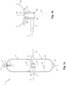
- Figure 1a shows a reactor according to the invention which is suitable for producing synthesis gas by partial oxidation of a hydrocarbon mixture.
- the reactor 1 has an upper reaction chamber 2 and a lower cooling chamber 7.
- the reaction chamber 2 and the cooling chamber 7 form the two main areas of the reactor 1.
- the reaction chamber 2 and the cooling chamber 7 are separated from one another by an intermediate floor 26.
- a fluidic connection between the reaction chamber 2 and the cooling chamber 7 is established by a gas guide pipe 14, which connects the reaction chamber 2 and the cooling chamber 7 to one another.
- the gas guide pipe 14 is designed as a passage through the intermediate floor 26 from the reaction chamber 2 into the cooling chamber 7.
- the reactor has a reactor jacket and an internal heat-resistant lining (not shown in detail) to withstand the reaction conditions of partial oxidation.
- the reaction chamber 2 has a feed 4 for fuel (hydrocarbon mixture) and oxidizing agent (oxygen or air) in an upper area (head area). Accordingly, a stream 5 of fuel and oxidizing agent flows through the feed 4.
- a burner 3, which is used during operation of the reactor 1 has a downward-facing burner flame 6, the hydrocarbon mixture is converted into a synthesis gas mixture by partial oxidation with oxygen.
- the synthesis gas stream 10 flowing from top to bottom in the interior of the reaction chamber essentially contains hydrogen, carbon monoxide and carbon dioxide. Other undesirable byproducts can be contained in the synthesis gas stream 10.
- the temperature of the synthesis gas stream 10 can be significantly above 1000 °C.
- this hot synthesis gas stream 10 To cool this hot synthesis gas stream 10, it first passes through a gas guide pipe 14 and then through the interior of the cooling chamber 7 before it leaves the reactor 1 via the synthesis gas outlet 11 and is subjected to further processing (for example drying and carbon dioxide separation).
- the gas guide tube 14 has an upper end (first end) which borders on the reaction chamber 2, in particular the interior of the reaction chamber 2. This upper end of the gas guide tube 14 is the gas inlet region 19 of the gas guide tube 14.
- the gas guide tube 14 also has a lower end (second end) which borders on the cooling chamber 7, in particular the interior of the cooling chamber 7. This lower end of the gas guide tube 14 is the gas outlet region 20 of the gas guide tube 14.
- the gas guide pipe 14, in Figure 1b shown enlarged, has an outer tube 21 and an inner tube 22, whereby an annular gap 23 is formed between the wall of the inner tube 22 and the outer tube 21.
- the gas guide tube 14 can be flowed through by coolant in the area of the annular gap through the annular gap 23. Coolant is supplied to the gas guide tube 14 via a coolant supply 8.
- the coolant supply 8 forms part of the cooling chamber 7 and extends through the side wall of the cooling chamber 7.
- the coolant supply 8 is designed as a tube, the interior of which is in fluid communication with the annular gap 23. This means that the outer tube 21 of the gas guide tube 14 has an opening which enables a passage from the coolant supply 8 to the annular gap 23 of the gas guide tube 14 (not shown).
- the coolant supply 8 is connected to the gas guide tube in the lower area or gas outlet area 20 in order to provide said fluidic connection with the annular gap 23.
- the coolant of the coolant stream 9 for example water, initially flows from bottom to top within the annular gap 23.
- the inner tube 22 has an opening to the annular gap 23 (not shown).
- the inner tube has an opening in this gas inlet region 19, which creates a fluidic connection between the space of the annular gap 23 and the interior of the inner tube 22.
- coolant of the coolant flow 9 can reach the inside of the inner tube 22 in particular, whereby the gas guide tube 14 is cooled from the inside.
- a guide plate 24 is arranged in the gas inlet area 19 of the gas guide tube, in the area of the opening of the inner tube 22 to the annular gap 23, a guide plate 24 is arranged.
- the guide plate 24 is connected to the inside of the inner tube 22 in a materially bonded manner, for example via a welded connection.
- the guide plate takes on the function of deflecting the coolant after it has left the opening of the annular gap 23 to the inner tube 22.
- the guide plate 24 therefore has the function of a film layer in particular, so that a film of coolant liquid that is as continuous as possible can form along the inside of the inner tube 22. This additionally cools the inner tube 22 from the inside. This also prevents deposits from forming on the inside of the inner tube 22.
- the gas outlet area 20 of the gas guide tube 14 has an orifice 25.
- the orifice 25 defines a constriction in the gas outlet area 20 of the gas guide tube 14.
- the orifice 25 reduces the flow cross-section of the gas guide tube 14 in the gas outlet area 20.
- This forms a coolant spray 13 (shown by dotted lines), which ensures efficient and complete mixing of the synthesis gas to be cooled with the coolant. This cools the synthesis gas stream, which was originally over 1000 °C, to below 300 °C.
- the cooled synthesis gas is discharged from the reactor via the synthesis gas outlet 11. Excess, non-evaporated coolant collects in the sump area of the cooling chamber 7.
- the collecting water can also be used as excess coolant 16, which collects in the sump area of the cooling chamber 7.
- This excess coolant is continuously discharged from the cooling chamber 7 via the coolant outlet 15 as excess coolant flow 17.
- the level of excess coolant is regulated by a level controller 18 so that it does not come into contact with the gas outlet area 20 of the gas guide pipe 14. In other words, the level of excess coolant 16 is regulated by the level controller 18 so that the gas guide pipe is never immersed in the coolant of the excess coolant 16.
Landscapes
- Chemical & Material Sciences (AREA)
- Organic Chemistry (AREA)
- Chemical Kinetics & Catalysis (AREA)
- Engineering & Computer Science (AREA)
- Combustion & Propulsion (AREA)
- Oil, Petroleum & Natural Gas (AREA)
- Health & Medical Sciences (AREA)
- General Health & Medical Sciences (AREA)
- Inorganic Chemistry (AREA)
- Devices And Processes Conducted In The Presence Of Fluids And Solid Particles (AREA)
- Physical Or Chemical Processes And Apparatus (AREA)
Abstract
Die Erfindung betrifft einen Reaktor zur Erzeugung von Synthesegas durch partielle Oxidation eines kohlenstoffhaltigen Brennstoffs, umfassend einen Reaktionsraum und einen Abkühlraum, wobei ein gekühltes Gasleitrohr den Reaktionsraum und den Abkühlraum miteinander verbindet. Das Gasleitrohr verfügt über einen an den Reaktionsraum angrenzenden Gaseinlassbereich und einen an den Abkühlraum angrenzenden Gasauslassbereich. Erfindungsgemäß ist vorgesehen, dass das Gasleitrohr ein Innenrohr und ein Außenrohr aufweist, wodurch zwischen dem Innenrohr und dem Außenrohr ein Ringspalt ausgebildet wird, wobei der Ringspalt fluidisch mit einer Kühlmittelzuführung verbunden ist, so dass dieser mit Kühlmittel durchströmbar ist, und das Innenrohr im Gaseinlassbereich des Gasleitrohrs eine Öffnung zum Ringspalt aufweist, und im Bereich dieser Öffnung ein Leitblech angeordnet ist, so dass auf der Innenseite des Innenrohrs ein Flüssigkeitsfilm aus Kühlmittel erzeugbar ist, und im Gasauslassbereich des Gasleitrohrs eine Blende angeordnet ist, so dass innerhalb des Abkühlraums ein Spray aus Kühlmittel erzeugbar ist.
Description
- Die Erfindung betrifft einen Reaktor zur Erzeugung von Synthesegas durch partielle Oxidation eines kohlenstoffhaltigen Brennstoffs. Die Erfindung zeichnet sich insbesondere durch eine verbesserte direkte Kühlung des Synthesegases im Reaktor aus.
- Die partielle Oxidation von kohlenstoffhaltigen gasförmigen, flüssigen oder festen Brennstoffen, insbesondere von Kohlenwasserstoffen, ist ein großtechnisch gängiges Verfahren zur Erzeugung von Wasserstoff-Kohlenmonoxid-Gemischen (Synthesegas). Bei der sogenannten Flugstromvergasung wird in einem Reaktionsraum der kohlenstoffhaltige Brennstoff zusammen mit einem sauerstoffhaltigen Oxidationsmittel und gegebenenfalls einem Moderator, zum Beispiel Wasserdampf und/oder Kohlendioxid, zu Synthesegas umgesetzt. Typische Bedingungen im Reaktor, insbesondere im Reaktionsraum, sind dabei hohe Temperaturen (1300 °C bis 1500 °C) und hohe Drücke (bis zu 100 bar).
- In Prozessführungen, in welchen die Wärme in dem Synthesegas nicht in einem Abhitzekessel genutzt werden kann, muss das heiße Synthesegas vor einer weiteren Reinigung und Nutzung gekühlt werden, typischerweise auf eine Temperatur von weniger als 300 °C. Dies erfolgt in der Regel durch direkten Kontakt, also direkte Kühlung, mit einem Kühlmittel. Das Kühlmittel wird in diesem Zusammenhang häufig als Quenchmedium bezeichnet. Bei dem Quenchmedium handelt es sich in der Regel um Wasser, in manchen Fällen (zum Beispiel bei der Kohlevergasung oder Biomassevergasung) auch um organische Flüssigkeiten.
- Diese Art der Kühlung, auch Quenchkühlung, ist in der einschlägigen Literatur beschrieben und dem Fachmann hinreichend bekannt. Grundsätzlich können drei Ausführungen dieser Art von Kühlung unterschieden werden, nämlich die Tauchquenche, die Freiquenche und das Quenchrohr.
- Bei der Tauchquenche schließt sich typischerweise direkt am Ausgang des Reaktionsraums ein in das Kühlmittel abgetauchtes Gasleitrohr an, welches das heiße Gas aus dem Reaktionsraum in ein Wasserreservoir leitet, wo es bei der Durchströmung des Wasserreservoirs abgekühlt wird. Solche Systeme sind beispielsweise in der
US 2010/0325957 A1 , derUS 2013/0189165 A1 , und derWO 2017/102945 A1 beschrieben. - Bei der Freiquenche wird das heiße Gas aus dem Reaktionsraum über ein Leitrohr direkt in den Abkühlraum (Quenchraum) geleitet, in den über eine oder mehrere Düsen Wasser eingespritzt wird. Solche Systeme sind beispielsweise in der
US 2007/0051043 A1 und in derUS 2009/0007487 A1 beschrieben. - Beim Quenchrohr wird die Kühlflüssigkeit mit hoher Geschwindigkeit in die in einem Rohr geführte Gasströmung über ein Düsensystem eingeströmt, bevor dieses zur direkten Kühlung mit einem Kühlmittel in den aufgeweiteten Quenchraum strömt. Ein solches System ist in der
DD 215 326 - Bei Verwendung einer Tauchquenche besteht der Nachteil, dass der Füllstand des Quenchwassers innerhalb des Abkühlraums des Reaktors, durch das das zu kühlende Gas geleitet wird, in einem engen Bereich kontrolliert werden muss. Ein zu hoher Füllstand kann leicht zu sich aufschaukelnden Druckschwankungen im Reaktorsystem führen. Bei zu niedrigem Füllstand besteht die Gefahr des Durchbruchs von ungekühltem Synthesegas mit einer dadurch möglichen Schädigung von Bauteilen.
- Die Verwendung einer Freiquench-Anordnung birgt die Gefahr, dass bei Verstopfung einzelner Düsen Teilbereiche des Gasstroms nicht ausreichend gekühlt werden, was mit der Gefahr der Bildung von heißen Gassträhnen und dadurch einer Überhitzung und Schädigung von Bauteilen einhergehen kann.
- Die Verwendung eines einfachen, nicht abgetauchten Gasleitrohres mit Wassereindüsung verringert zwar die Gefahren der Bildung von heißen Gassträhnen bei Verstopfung oder Strahlablenkung von einzelnen Düsen, hat jedoch bei höheren Betriebsdrücken den Nachteil, dass aufgrund der hohen Dichte und Viskosität des Synthesegases das Kühlmedium einen hohen Impuls benötigt, um bis in den Kern der Gasströmung eindringen zu können. Hierzu erforderlich sind ein hoher Differenzdruck und ein ausreichend großer Kühlmittelstrahldurchmesser, was der Anforderung nach der Bildung von möglichst kleinen Kühlmitteltropfen für eine schnelle und effektive Kühlung entgegensteht. Durch eine unzureichende Zerstäubung oder ein nicht ausreichendes Eindringen des Kühlmediums in den zu kühlenden Gasstrahl ist insbesondere bei hohen Drücken und transienten Betriebszuständen (Anfahren des Reaktors von niedrigem Druck auf Normallast) die sichere Abkühlung des Gases nicht gewährleistet.
- Allgemein ist es daher eine Aufgabe der vorliegenden Erfindung, die vorgenannten Nachteile des Standes der Technik zumindest teilweise zu überwinden. Dies gilt insbesondere in Zusammenhang mit den für ein nicht abgetauchtes Gasleitrohr (Quenchrohr) beschriebenen Nachteile.
- Insbesondere besteht eine Aufgabe der vorliegenden Erfindung darin, die Abkühlung des heißen Synthesegases durch direkte Kühlung mit einem Kühlmittel so zu realisieren, dass der gesamte abzukühlende Gasstrom erfasst wird, so dass sich keine heißen Synthesegassträhnen ausbilden können, was zu einer Überhitzung und Schädigung der drucktragenden Wand des Abkühlraums oder stromabwärts geschalteten Bauteilen führen könnte.
- Weiterhin besteht eine Aufgabe der vorliegenden Erfindung darin, die Abkühlung des Synthesegases so zu gestalten, dass diese über einen weiten Betriebsbereich vom Anfahren des Reaktors unter Umgebungsbedingungen, bis zu voller Last bei hohem Druck, drastisch geänderter Strömungsgeschwindigkeit, Dichte und Zähigkeit der Medien, zuverlässig und sicher erfolgt.
- Ein Beitrag zur mindestens teilweisen Lösung mindestens einer der obigen Aufgaben wird durch den unabhängigen Anspruch geleistet. Die abhängigen Ansprüche stellen bevorzugte Ausführungsformen bereit, die zur mindestens teilweisen Erfüllung mindestens einer der Aufgaben beitragen.
- Die Ausdrücke "aufweisend", "umfassend" oder "beinhaltend" etc. schließen nicht aus, dass weitere Elemente, Inhaltsstoffe etc. enthalten sein können. Der unbestimmte Artikel "ein" schließt nicht aus, dass eine Mehrzahl vorhanden sein kann.
- Die Aufgaben der Erfindung werden zumindest teilweise gelöst durch einen Reaktor zur Erzeugung von Synthesegas durch partielle Oxidation eines kohlenstoffhaltigen Brennstoffs, umfassend
- (a) einen Reaktionsraum mit einem Brenner, einer Brennstoffzuführung und einer Oxidationsmittelzuführung, zur Erzeugung des Synthesegases aus dem Brennstoff und dem Oxidationsmittel im Reaktionsraum;
- (b) einen Abkühlraum, aufweisend eine Kühlmittelzuführung, einen Synthesegasauslass, sowie einen Kühlmittelauslass, zur Kühlung des Synthesegases durch direkte Kühlung mit einem Kühlmittel;
- (c) ein Gasleitrohr, welches den Reaktionsraum und den Abkühlraum miteinander verbindet, wobei
das Gasleitrohr einen an den Reaktionsraum angrenzenden Gaseinlassbereich und einen an den Abkühlraum angrenzenden Gasauslassbereich aufweist, - Gemäß der Erfindung wird die Strömung des heißen Synthesegases nach Austritt aus dem Reaktionsraum zunächst durch ein gekühltes Gasleitrohr geführt. Das Gasleitrohr kann auch als Quenchrohr bezeichnet werden. Das Gasleitrohr ist als doppelwandiges System mit Innenrohr und Außenrohr ausgeführt, wodurch es einen Ringspalt ausbildet. Der Ringspalt ist in Fluidverbindung mit der Kühlmittelzuführung, wodurch das von Synthesegas durchströmte Volumen des Gasleitrohrs gekühlt wird. Das Innenrohr verfügt im Gaseinlassbereich des Gasleitrohrs über eine Öffnung zum Ringspalt, wodurch eine fluidische Verbindung zwischen dem Ringspalt und dem Innenrohr, insbesondere dem Innenraum des Innenrohrs und/oder der Innenseite des Innenrohrs, ausgebildet wird. Es können auch mehrere solcher Öffnungen vorhanden sein.
- Im Bereich der Öffnung des Ringspalts zur Innenseite des Innenrohrs ist ein Leitblech angeordnet. Durch das Leitblech wird das aus der Öffnung austretende Kühlmittel so umgelenkt, dass auf der Innenseite des Innerohrs ein Flüssigkeitsfilm ausbildbar ist. Dadurch wird das Gasleitrohr zusätzlich auf seiner Innenseite gekühlt und dadurch vor einer Überhitzung geschützt. Weiterhin bietet die Ausbildung eines Wasserfilms auf der Innenseite des Gasleitrohres durch kontinuierliche Strömung auf der Innenseite des Innenrohrs einen effektiven Schutz vor möglichen Ablagerungen.
- Ferner ist im Gasauslassbereich des Gasleitrohres eine Blende angeordnet. Durch die Blende wird die durchströmbare Querschnittsfläche des Gasleitrohres, also der Strömungsquerschnitt des Gasleitrohrs, im Bereich des Gasauslassbereichs verringert. Dies führt zu Turbulenzen im Gasauslassbereich des Gasleitrohres, insbesondere im Bereich der Blende, wodurch das Kühlmittel von dem strömenden Synthesegas zerstäubt wird, und dadurch innerhalb des Abkühlraums ein Spray aus Kühlmittel ausgebildet wird. Die Ausbildung dieses Kühlmittelsprays führt zu einer innigen Vermischung des heißen Gasstroms mit dem Kühlmittel. Dadurch ist sichergestellt, dass der vollständige Synthesegasstrom erfasst und abgekühlt wird.
- Das erfindungsgemäße Abkühlsystem des Reaktors bietet ferner den Vorteil, dass bezüglich des Kühlmittels kein hoher Druck für eine Eindüsung erforderlich ist. Da das System grundsätzlich ohne Düsen ausgeführt werden kann, ist die Gefahr einer (teilweisen) Verstopfung der Kühlmittelzufuhr und einer dadurch verminderten Kühlung unter Ausbildung heißer Synthesegassträhnen stark gemindert.
- Der erfindungsgemäße Reaktor ist zur Erzeugung von Synthesegas durch partielle Oxidation eines kohlenstoffhaltigen Brennstoffs eingerichtet. Bei dem kohlenstoffhaltigen Brennstoff kann es sich um jeden gasförmigen, flüssigen oder festen Brennstoff handeln, der zur Synthesegaserzeugung durch partielle Oxidation geeignet ist. Gemäß einer Ausführungsform ist der Reaktorfür eine Flugstromvergasung konfiguriert. Vorzugsweise handelt es sich bei dem kohlenstoffhaltigen Brennstoff um einen kohlenwasserstoffhaltigen Brennstoff. Das Oxidationsmittel enthält vorzugsweise Sauerstoff. Beispiele für geeignete Oxidationsmittel sind Luft, mit Sauerstoff angereicherte Luft, oder reiner Sauerstoff. Das erzeugte Synthesegas enthält zumindest Wasserstoff und Kohlenmonoxid, sowie in der Regel Kohlendioxid als weiteres Produkt der Synthesegasbildungsreaktion.
- Der Reaktionsraum des Reaktors ist für die eigentliche partielle Oxidation konfiguriert. Typische Temperaturen, bei welchen die partielle Oxidation abläuft, sind 1300 °C bis 1500 °C. Der Druck im Reaktionsraum kann bis zu 100 bar betragen.
- Entsprechend verfügt der Reaktionsraum über zumindest einen Brenner. Ferner verfügt der Reaktionsraum über eine Brennstoffzuführung, welche für die Zuführung von Brennstoff in den Reaktionsraum des Reaktors und/oder zu dem mindestens einen Brenner eingerichtet ist. Ferner verfügt der Reaktionsraum über eine Oxidationsmittelzuführung, welche für die Zuführung von Oxidationsmittel in den Reaktionsraum des Reaktors und/oder zu dem mindestens einen Brenner eingerichtet ist.
- Der Abkühlraum des Reaktors ist für die Abkühlung des im Reaktionsraum erzeugten heißen Synthesegases eingerichtet. Die Abkühlung des heißen Synthesegases erfolgt dabei durch direkte Kühlung des Synthesegases, das heißt durch direkte Wärmeübertragung vom Synthesegas auf das Kühlmittel durch Vermischen dieser beiden Medien und zumindest teilweise Verdampfung des Kühlmediums. Diese direkte Kühlung ist von einer indirekten Kühlung, wie beispielsweise in einem Wärmeübertrager, zu unterscheiden.
- Der Abkühlraum weist eine Kühlmittelzuführung auf. Die Kühlmittelzuführung ist zum Zuführen von Kühlmittel zum Abkühlraum des Reaktors eingerichtet. Bevor das Kühlmittel in den Abkühlraum des Reaktors gelangt, durchströmt es zunächst den Ringspalt des Gasleitrohres und die Innenseite des Innenrohrs des Gasleitrohrs. Die Kühlmittelzuführung ist vorzugsweise zumindest teilweise innerhalb des Abkühlraums angeordnet, erstreckt sich somit zumindest teilweise durch den Abkühlraum hindurch. Bei der Kühlmittelzuführung handelt es sich vorzugsweise um eine rohrförmige Zuführung.
- Der Abkühlraum weist ferner einen Synthesegasauslass auf. Der Synthesegasauslass ist zum Abführen des abgekühlten Synthesegas-Kühlmittel-Gemischs aus dem Abkühlraum des Reaktors eingerichtet. Unter Synthesegas-Kühlmittel-Gemisch wird in diesem Zusammenhang eine Mischung aus abgekühltem Synthesegas und verdampftem Kühlmittel verstanden. Ferner kann das vorgenannte Gemisch einen Anteil an Moderatordampf enthalten, welcher zur thermischen Steuerung der Reaktion in den Reaktionsraum eingebracht wurde. Bei dem Synthesegasauslass handelt es sich vorzugsweise um eine rohrförmige Abführung. Der Synthesegasauslass kann auch als Kaltgasauslass bezeichnet werden.
- Der Abkühlraum verfügt weiterhin über einen Kühlmittelauslass. Der Kühlmittelauslass ist zum Abführen des überschüssigen Kühlmittels aus dem Abkühlraum des Reaktors eingerichtet. Überschüssiges flüssiges Kühlmittel, welches den Reaktor nicht gasförmig zusammen mit dem abgekühlten Synthesegas über den Synthesegasauslass verlässt, wird somit über den Kühlmittelauslass aus dem Reaktor ausgeleitet. Bei dem Kühlmittelauslass handelt es sich vorzugsweise um eine rohrförmige Abführung. Vorzugsweise ist der Kühlmittelauslass im Sumpfbereich des Abkühlraums angeordnet. Im Sumpfbereich des Abkühlraums kann sich überschüssiges Kühlmittel sammeln. Der Füllstand des überschüssigen Kühlmittels kann über eine Füllstandsregelung kontrolliert werden, über welche der Abkühlraum des Reaktors vorzugsweise verfügt.
- Der Reaktionsraum und der Abkühlraum des Reaktors sind über ein Gasleitrohr miteinander verbunden. Das Gasleitrohr stellt somit eine Durchführung für das abzukühlende Synthesegas vom Reaktionsraum in den Abkühlraum dar.
- Das Gasleitrohr verfügt über einen an den Reaktionsraum angrenzenden Gaseinlassbereich. Der Gaseinlassbereich des Gasleitrohres kann auch als erstes Ende des Gasleitrohres bezeichnet werden. Dieses erste Ende grenzt unmittelbar an den Reaktionsraum an, das Gasleitrohr "sieht" somit zunächst an seinem ersten Ende oder am Gaseinlassbereich das heiße, noch nicht abgekühlte Synthesegas.
- Das Gasleitrohr verfügt ferner über einen an den Abkühlraum angrenzenden Gasauslassbereich. Der Gasauslassbereich des Gasauslassrohres kann auch als zweites Ende des Gasleitrohrs bezeichnet werden. Dieses zweite Ende grenzt unmittelbar an den Abkühlraum an. Nach passieren dieses Gasauslassbereichs oder zweiten Endes tritt das vorgekühlte Synthesegas somit in den Abkühlraum des Reaktors ein.
- Im Bereich des Gasauslassbereichs oder zweiten Endes des Gasleitrohres ist eine Blende angeordnet. Die Blende ist so eingerichtet, dass diese gegenüber dem Strömungsquerschnitt des Gasleitrohres eine Engstelle definiert, somit im Bereich der Blende der Strömungsquerschnitt des Gasleitrohres vermindert ist. Vorzugsweise vermindert die Blende den Strömungsquerschnitt des Gasleitrohres um einen Faktor von 1,5 bis 16,0, vorzugsweise um einen Faktor von 2,0 bis 7,0.
- Eine bevorzugte Ausführung des Reaktors ist dadurch gekennzeichnet, dass zwischen dem Reaktionsraum und dem Abkühlraum ein Zwischenboden angeordnet ist, welcher den Reaktionsraum und den Abkühlraum räumlich voneinander trennt, und sich das Gasleitrohr als Durchführung durch den Zwischenboden hindurch erstreckt.
- Bei dem Zwischenboden handelt es sich insbesondere um einen tragenden Zwischenboden, welcher eine räumliche und fluiddichte Trennung zwischen dem Reaktionsraum und dem Abkühlraum definiert. Das Gasleitrohr erstreckt sich vom Reaktionsraum durch den Zwischenboden in den Abkühlraum, und definiert dadurch eine Durchführung für Fluide vom Reaktionsraum in den Abkühlraum.
- Eine bevorzugte Ausführung des Reaktors ist dadurch gekennzeichnet, dass der Reaktionsraum den oberen Bereich des Reaktors bildet und der Abkühlraum den unteren Bereich des Reaktors bildet.
- Insbesondere ist der Reaktor vertikal derart angeordnet, dass der Durchfluss von Reaktionsmedien und Kühlmedien von oben nach unten erfolgen kann. Insbesondere ist der zumindest eine Brenner und sind die Zuführungen für Brennstoff und Oxidationsmittel in einem Kopfbereich des Reaktors, insbesondere in einem Kopfbereich des Reaktionsraums, angeordnet. Eine solche Anordnung wird auch als von oben befeuert oder top fired bezeichnet.
- Eine bevorzugte Ausführung des Reaktors ist dadurch gekennzeichnet, dass das Gasleitrohr vertikal angeordnet ist.
- Das Gasleitrohr ist vorzugsweise vertikal, oder zumindest im Wesentlichen vertikal angeordnet. Dies erlaubt einen natürlichen, durch Gravitation ermöglichten Fluss von Synthesegas und des Kühlmittels durch das Gasleitrohr.
- Eine bevorzugte Ausführung des Reaktors ist dabei dadurch gekennzeichnet, dass das Gasleitrohr in einem unteren Bereich fluidisch mit der Kühlmittelzuführung verbunden ist, so dass der Ringspalt von unten nach oben mit Kühlmittel durchströmbar ist.
- Der Ringspalt des Gasleitrohrs ist vorzugsweise im Gasauslassbereich fluidisch mit der Kühlmittelzuführung verbunden. Dadurch ist sichergestellt, dass das Gasleitrohr über die gesamte Länge im Ringspalt von Kühlmittel durchströmt wird. Dadurch wird eine Kühlung des Gasleitrohres über den Fluss durch den Ringspalt ermöglicht.
- Insbesondere bei vertikaler Anordnung des Gasleitrohrs ist der Ringspalt vorzugsweise daher in einem unteren Bereich des Gasleitrohres fluidisch mit der Kühlmittelzuführung verbunden, so dass der Ringspalt über die maximale Länge des Gasleitrohres von unten nach oben von Kühlmittel durchströmt werden kann.
- Eine bevorzugte Ausführung des Reaktors ist dadurch gekennzeichnet, dass das Leitblech einen parallel zum Innenrohr verlaufenden Bereich aufweist.
- Der parallel zum Innenrohr verlaufende Bereich des Leitblechs ist vorzugsweise über ein Ende dieses Bereichs, insbesondere ein oberes Ende dieses Bereichs, oberhalb der Öffnung des Innenrohrs zum Ringspalt mit einer Innenseite des Innenrohrs verbunden. Diese Verbindung kann über ein weiteres Element des Leitblechs, beispielsweise ein im Wesentlichen horizontal verlaufendes Verbindungselement, bewirkt werden.
- Vorzugsweise handelt es sich bei den genannten Verbindungen um stoffschlüssige Verbindungen, wie beispielsweise Schweißverbindungen.
- Bei vertikaler Anordnung des Gasleitrohrs ist das Leitblech grundsätzlich oberhalb der Öffnung des Innenrohrs zum Ringspalt befestigt, um so einen Fluss des Kühlmittels entlang der Innenseite des Innenrohrs von oben nach unten zu bewirken.
- Eine bevorzugte Ausführung des Reaktors ist dadurch gekennzeichnet, dass der Synthesegasauslass seitlich am Abkühlraum des Reaktors angeordnet ist.
- Wie bereits erwähnt, kann der Synthesegasauslass auch als Kaltgasauslass bezeichnet werden. Dieser Kaltgasauslass dient dem Ausleiten des abgekühlten Gemischs aus Synthesegas und gasförmigem Kühlmittel, insbesondere Synthesegas und Wasserdampf, aus dem Abkühlraum des Reaktors. Vorzugsweise ist der Synthesegasauslass als im Wesentlichen horizontal verlaufendes Rohr oder als horizontal verlaufendes Rohr angeordnet. Weiter bevorzugt ist das Rohr möglichst weit oben im Bereich des Abkühlraums angeordnet, so dass sich möglichst wenig Synthesegas-Kühlmittel-Gemisch in einem kaum durchströmten Totraum oberhalb des Synthesegasauslasses sammeln kann.
- Vorzugsweise ist auch die Kühlmittelzuführung als im Wesentlichen horizontal verlaufendes Rohr oder als horizontal verlaufendes Rohr seitlich am Abkühlraum des Reaktors angeordnet. Gemäß einer Ausführungsform weist die Kühlmittelzuführung eine Neigung auf, insbesondere ein Gefälle vom Randbereich des Abkühlraums in Richtung mittigem Bereich des Abkühlraums. Dabei erstreckt sich die Kühlmittelzuführung insbesondere durch eine Seitenwandung des Abkühlraums des Reaktors.
- Weiter bevorzugt ist der Kühlmittelauslass in einem unteren Bereich des Abkühlraums des Reaktors angeordnet.
- Vorzugsweise ist der Kühlmittelauslass in einem unteren Bereich oder Sumpfbereich des Abkühlraums des Reaktors angeordnet. Insbesondere erstreckt sich der Kühlmittelauslass durch eine untere Wandung, in der Regel den Boden, des Abkühlraums hindurch. Der Kühlmittelauslass kann dabei in einem zentralen Bereich des Bodens angeordnet sein, oder seitlich versetzt. Bei zentraler Anordnung ist der Kühlmittelauslass vorzugsweise als vertikales Rohr ausgestaltet. Bei seitlich versetzter Anordnung kann der Kühlmittelauslass schräg angeordnet sein.
- Oberhalb des Kühlmittelauslasses kann sich überschüssiges Kühlmittel innerhalb des Abkühlraums sammeln. Die Menge dieses überschüssigen Kühlmittels ist über den Füllstand geregelt. Dabei ist bevorzugt, dass der Füllstand stets so kontrolliert wird, dass sich der Füllstand, also die obere Grenze der stehenden Kühlflüssigkeit, niemals oberhalb des Gasauslassbereichs des Gasleitrohres befindet.
- Gemäß einer Ausführungsform ist der Reaktor daher so eingerichtet, dass der Abkühlraum über eine Füllstandsregelung für Kühlmittel, insbesondere für überschüssiges Kühlmittel, verfügt, wobei die Füllstandsregelung so eingerichtet ist, dass sich der Füllstand im Betrieb des Reaktors unterhalb des Gasauslassbereichs des Gasleitrohrs befindet.
- Der Reaktor ist somit vorzugsweise so eingerichtet, dass der Gasauslassbereich des Gasleitrohrs so angeordnet ist, dass dieser unter Betriebsbedingungen nicht in eine Flüssigkeit, insbesondere nicht in Kühlmittelflüssigkeit, eintaucht. Der Reaktor ist dementsprechend bevorzugt als Reaktor mit Quenchrohr als Kühlsystem eingerichtet, nicht mit einem Tauchrohr (Tauchquenche) als Kühlsystem.
- Gemäß einer Ausführungsform kann der Abkühlraum des Reaktors zusätzliche Düsen oder andere geeignete Vorrichtungen zum Einspritzen von Kühlmittel in den Abkühlraum beinhalten, wodurch der Reaktor zusätzlich über ein als Freiquenche zu bezeichnendes Kühlsystem verfügen würde.
- Eine bevorzugte Ausführung des Reaktors ist dadurch gekennzeichnet, dass das Kühlmittel Wasser beinhaltet, vorzugsweise aus Wasser besteht.
- Eine bevorzugte Ausführungsform des Reaktors ist dadurch gekennzeichnet, dass innerhalb des Ringspalts ein Widerstandselement angeordnet ist, welches einen Druckverlust in Bezug auf die Kühlmittelströmung innerhalb des Ringspalts bewirkt.
- Gemäß einem Beispiel handelt es sich beim dem Widerstandselement um einen umlaufenden Ring, vorzugsweise mit Stegen.
- Durch die Anordnung eines Widerstandselements innerhalb des Ringspalts wird die Gleichverteilung der Strömung des Kühlmittels innerhalb des Ringspalts verbessert. Mit anderen Worten, die Strömung des Kühlmittels innerhalb des Ringspalts wird dadurch vergleichmäßigt.
- Eine bevorzugte Ausführungsform des Reaktors ist dadurch gekennzeichnet, dass das Innenrohr im Gasauslassbereich des Gasleitrohres eine Öffnung zum Ringspalt aufweist, wodurch ein Kühlmittel-Bypass-Strom in den Innenraum des Gasleitrohres ausbildbar ist. Es können auch mehrere solcher Öffnungen vorhanden sein.
- Durch eine weitere Öffnung des Innenrohrs im Bereich des Gasauslassbereichs kann ein Kühlmittel-Bypass-Strom erzeugt werden, welcher Ablagerungen im GasauslassBereich des Ringspalts, insbesondere im unteren Bereich des Ringspalts, verhindert. Solche Ablagerungen können sich insbesondere bei ungleichmäßiger Kühlmittel-Zufuhr oder bei einer ungleichmäßigen oder schlechten Kühlung dieses Bereichs bilden.
- Die Erfindung wird im Folgenden durch Zeichnungen genauer dargestellt, wobei die Zeichnungen keine Beschränkung der Erfindung bedeuten. Die Zeichnungen sind nicht maßstabsgetreu.
- Es zeigt
- Figur 1a
- eine Übersichtsdarstellung eines erfindungsgemäßen Reaktors, und
- Figur 1b
- eine Detaildarstellung eines Teils des erfindungsgemäßen Reaktors, in welcher die Komponenten des Gasleitrohres vergrößert dargestellt sind.
-
Figur 1a zeigt einen erfindungsgemäßen Reaktor, welcher zur Erzeugung von Synthesegas durch partielle Oxidation eines Kohlenwasserstoff-Gemischs geeignet ist. - Der Reaktor 1 verfügt über einen oberen Reaktionsraum 2 und einen unteren Abkühlraum 7. Der Reaktionsraum 2 und der Abkühlraum 7 bilden die beiden Hauptbereiche des Reaktors 1. Dabei sind der Reaktionsraum 2 und der Abkühlraum 7 durch einen Zwischenboden 26 voneinander separiert. Ein fluidische Verbindung zwischen dem Reaktionsraum 2 und dem Abkühlraum 7 wird durch ein Gasleitrohr 14 hergestellt, welches den Reaktionsraum 2 und den Abkühlraum 7 miteinander verbindet. Das Gasleitrohr 14 ist dabei als Durchführung durch den Zwischenboden 26 vom Reaktionsraum 2 in den Abkühlraum 7 eingerichtet.
- Der Reaktor verfügt über einen Reaktormantel und eine innenseitig hitzeresistente Ausmauerung (im Detail nicht gezeigt), um den Reaktionsbedingungen der partiellen Oxidation standzuhalten.
- Der Reaktionsraum 2 verfügt in einem oberen Bereich (Kopfbereich) über eine Zuführung 4 für Brennstoff (Kohlenwasserstoff-Gemisch) und Oxidationsmittel (Sauerstoff oder Luft). Entsprechend durchströmt ein Strom 5 aus Brennstoff und Oxidationsmittel die Zuführung 4. Durch einen Brenner 3, welcher im Betrieb des Reaktors 1 eine nach unten gerichtete Brennerflamme 6 aufweist, wird das Kohlenwasserstoff-gemisch durch partielle Oxidation mit Sauerstoff zu einem Synthesegasgemisch umgesetzt. Der von oben nach unten im Innenraum des Reaktionsraums strömende Synthesegasstrom 10 enthält im Wesentlichen Wasserstoff, Kohlenmonoxid und Kohlendioxid. Andere unerwünschte Nebenprodukte können im Synthesegasstrom 10 enthalten sein. Die Temperatur des Synthesegasstroms 10 kann bei deutlich über 1000 °C liegen.
- Zur Abkühlung dieses heißen Synthesegasstroms 10 passiert dieses zunächst ein Gasleitrohr 14, und anschließend den Innenraum des Abkühlraums 7, bevor es den Reaktor 1 über den Synthesegasauslass 11 verlässt und einer weiteren Verarbeitung (zum Beispiel Trocknung und Kohlendioxidabscheidung) unterzogen wird.
- Das Gasleitrohr 14 verfügt über ein oberes Ende (erstes Ende), welches an den Reaktionsraum 2, insbesondere den Innenraum des Reaktionsraums 2, angrenzt. Dieses obere Ende des Gasleitrohrs 14 ist der Gaseinlassbereich 19 des Gasleitrohrs 14. Das Gasleitrohr 14 verfügt weiterhin über ein unteres Ende (zweites Ende), welches an den Abkühlraum 7, insbesondere den Innenraum des Abkühlraums 7, angrenzt. Dieses untere Ende des Gasleitrohrs 14 ist der Gasauslassbereich 20 des Gasleitrohrs 14.
- Das Gasleitrohr 14, in
Figur 1b vergrößert dargestellt, verfügt über ein Außenrohr 21 und ein Innenrohr 22, wodurch zwischen der Wandung des Innenrohrs 22 und des Außenrohrs 21 ein Ringspalt 23 ausgebildet wird. Durch den Ringspalt 23 ist das Gasleitrohr 14 im Bereich des Ringspalts von Kühlmittel durchströmbar. Kühlmittel wird dem Gasleitrohr 14 über eine Kühlmittelzuführung 8 zugeführt. Die Kühlmittelzuführung 8 bildet einen Teil des Abkühlraums 7 und erstreckt sich durch die Seitenwandung des Abkühlraums 7. Die Kühlmittelzuführung 8 ist als Rohr ausgestaltet, dessen Innenraum in Fluidverbindung mit dem Ringspalt 23 steht. Das heißt, das Außenrohr 21 des Gasleitrohrs 14 weist eine Öffnung auf, welche einen Durchgang von der Kühlmittelzuführung 8 zum Ringspalt 23 des Gasleitrohrs 14 ermöglicht (nicht gezeigt). Die Kühlmittelzuführung 8 ist im unteren Bereich oder Gasauslassbereich 20 mit dem Gasleitrohr verbunden, um besagte fluidische Verbindung mit dem Ringspalt 23 auszubilden. Dadurch strömt das Kühlmittel des Kühlmittelstroms 9, zum Beispiel Wasser, zunächst innerhalb des Ringspalts 23 von unten nach oben. - In einem oberen Bereich oder Gaseinlassbereich 19 des Gasleitrohres 14 weist das Innenrohr 22 eine Öffnung zum Ringspalt 23 auf (nicht gezeigt). Mit anderen Worten, das Innenrohr verfügt in diesem Gaseinlassbereich 19 über eine Öffnung, welche eine fluidische Verbindung zwischen dem Raum des Ringspalts 23 und dem Innenraum des Innenrohrs 22 herstellt. Dadurch kann Kühlmittel des Kühlmittelstroms 9 insbesondere auf die Innenseite des Innenrohrs 22 gelangen, wodurch das Gasleitrohr 14 von innen gekühlt wird.
- Im Gaseinlassbereich 19 des Gasleitrohres ist im Bereich der Öffnung des Innenrohrs 22 zum Ringspalt 23 ein Leitblech 24 angeordnet. Insbesondere ist das Leitblech 24 stoffschlüssig, beispielsweise über eine Schweißverbindung, mit der Innenseite des Innenrohrs 22 verbunden. Das Leitblech übernimmt dabei die Funktion des Umlenkens des Kühlmittels, nachdem dieses die Öffnung des Ringspalts 23 zum Innenrohr 22 verlassen hat. Das Leitblech 24 weist somit insbesondere die Funktion eines Filmlegers auf, so dass sich entlang der Innenseite des Innenrohrs 22 ein möglichst durchgehender Film aus Kühlmittelflüssigkeit ausbilden kann. Dadurch wird das Innenrohr 22 zusätzlich von innen gekühlt. Ferner wird dadurch verhindert, dass sich auf der Innenseite des Innenrohrs 22 Ablagerungen bilden können.
- Der Gasauslassbereich 20 des Gasleitrohres 14 verfügt über eine Blende 25. Die Blende 25 definiert eine Engstelle im Gasauslassbereich 20 des Gasleitrohres 14. Durch die Blende 25 wird der Strömungsquerschnitt des Gasleitrohres 14 im Gasauslassbereich 20 verringert. Dadurch bildet sich ein Kühlmittelspray 13 (dargestellt durch gepunktete Linien) aus, welches für eine effiziente und vollständige Vermengung des abzukühlenden Synthesegases mit dem Kühlmittel sorgt. Dadurch wird der ursprünglich über 1000 °C heiße Synthesegasstrom auf unter 300 °C abgekühlt.
- Das abgekühlte Synthesegas wird über den Synthesegasauslass 11 aus dem Reaktor ausgeleitet. Überschüssiges, nicht verdampftes Kühlmittel sammelt sich im Sumpfbereich des Abkühlraums 7. Das sich sammelnde Wasser kann auch als Kühlmittelüberschuss 16 bezeichnet werden, welcher sich im Sumpfbereich des Abkühlraums 7 sammelt. Dieser Kühlmittelüberschuss wird kontinuierlich über den Kühlmittelauslass 15 als Kühlmittelüberschussstrom 17 aus dem Abkühlraum 7 ausgeleitet. Der Füllstand an Kühlmittelüberschuss wird über einen Füllstandsregler 18 so geregelt, dass dieser nicht mit dem Gasauslassbereich 20 des Gasleitrohres 14 in Berührung kommt. Mit anderen Worten, der Füllstand an Kühlmittelüberschuss 16 wird über den Füllstandsregler 18 so geregelt, dass das Gasleitrohr zu keinem Zeitpunkt in das Kühlmittel des Kühlmittelüberschusses 16 eintaucht.
-
- 1
- Reaktor
- 2
- Reaktionsraum
- 3
- Brenner
- 4
- Brennstoff- und Oxidationsmittelzuführung
- 5
- Strom aus Brennstoff und Oxidationsmittel
- 6
- Brennerflamme
- 7
- Abkühlraum
- 8
- Kühlmittelzuführung
- 9
- Kühlmittelstrom
- 10
- Heißer Synthesegasstrom
- 11
- Synthesegasauslass
- 12
- Strom aus abgekühltem Synthesegas und Kühlmittel
- 13
- Kühlmittelspray
- 14
- Gasleitrohr
- 15
- Kühlmittelauslass
- 16
- Kühlmittelüberschuss
- 17
- Kühlmittelüberschussstrom
- 18
- Füllstandregler für Kühlmittelüberschuss
- 19
- Gaseinlassbereich des Gasleitrohres
- 20
- Gasauslassbereich des Gasleitrohres
- 21
- Außenrohr des Gasleitrohres
- 22
- Innenrohr des Gasleitrohres
- 23
- Ringspalt
- 24
- Leitblech
- 25
- Blende
- 26
- Zwischenboden
Claims (10)
- Reaktor (1) zur Erzeugung von Synthesegas durch partielle Oxidation eines kohlenstoffhaltigen Brennstoffs, umfassend(a) einen Reaktionsraum (2) mit einem Brenner (3), einer Brennstoffzuführung und einer Oxidationsmittelzuführung (4), zur Erzeugung des Synthesegases aus dem Brennstoff und dem Oxidationsmittel im Reaktionsraum (2);(b) einen Abkühlraum (7), aufweisend eine Kühlmittelzuführung (8), einen Synthesegasauslass (11), sowie einen Kühlmittelauslass (15), zur Kühlung des Synthesegases durch direkte Kühlung mit einem Kühlmittel;(c) ein Gasleitrohr (14), welches den Reaktionsraum (2) und den Abkühlraum (7) miteinander verbindet, wobei das Gasleitrohr (14) einen an den Reaktionsraum (2) angrenzenden Gaseinlassbereich (19) und einen an den Abkühlraum angrenzenden Gasauslassbereich (20) aufweist,dadurch gekennzeichnet, dassdas Gasleitrohr (14) ein Innenrohr (22) und ein Außenrohr (21) aufweist, wodurch zwischen dem Innenrohr (22) und dem Außenrohr (21) ein Ringspalt (23) ausgebildet wird, wobei der Ringspalt (23) fluidisch mit der Kühlmittelzuführung (8) verbunden ist, so dass dieser mit Kühlmittel durchströmbar ist, unddas Innenrohr (22) im Gaseinlassbereich (19) des Gasleitrohrs (14) eine Öffnung zum Ringspalt (23) aufweist, und im Bereich dieser Öffnung ein Leitblech (24) angeordnet ist, so dass auf der Innenseite des Innenrohrs (22) ein Flüssigkeitsfilm aus Kühlmittel erzeugbar ist, undim Gasauslassbereich (20) des Gasleitrohrs (14) eine Blende (25) angeordnet ist, so dass innerhalb des Abkühlraums (7) ein Spray (13) aus Kühlmittel erzeugbar ist.
- Reaktor nach Anspruch 1, dadurch gekennzeichnet, dass zwischen dem Reaktionsraum (2) und dem Abkühlraum (7) ein Zwischenboden (26) angeordnet ist, welcher den Reaktionsraum (2) und den Abkühlraum (7) räumlich voneinander trennt, und sich das Gasleitrohr (14) als Durchführung durch den Zwischenboden (26) hindurch erstreckt.
- Reaktor nach einem der vorherigen Ansprüche, dadurch gekennzeichnet, dass der Reaktionsraum (2) den oberen Bereich des Reaktors (1) bildet und der Abkühlraum (7) den unteren Bereich des Reaktors bildet.
- Reaktor nach Anspruch 3, dadurch gekennzeichnet, dass das Gasleitrohr (14) vertikal angeordnet ist.
- Reaktor nach Anspruch 4, dadurch gekennzeichnet, dass das Gasleitrohr (14) in einem unteren Bereich fluidisch mit der Kühlmittelzuführung (8) verbunden ist, so dass der Ringspalt (23) von unten nach oben mit Kühlmittel durchströmbar ist.
- Reaktor nach einem der vorherigen Ansprüche, dadurch gekennzeichnet, dass das Leitblech (24) einen parallel zum Innenrohr (22) verlaufenden Bereich aufweist.
- Reaktor nach einem der vorherigen Ansprüche, dadurch gekennzeichnet, dass der Abkühlraum (7) über eine Füllstandsregelung (18) für Kühlmittel, insbesondere für überschüssiges Kühlmittel, verfügt, wobei die Füllstandsregelung (18) so eingerichtet ist, dass sich der Füllstand im Betrieb des Reaktors (1) unterhalb des Gasauslassbereichs (20) des Gasleitrohrs (14) befindet.
- Reaktor nach einem der vorherigen Ansprüche, dadurch gekennzeichnet, dass das Kühlmittel Wasser beinhaltet, vorzugsweise aus Wasser besteht.
- Reaktor nach einem der vorherigen Ansprüche, dadurch gekennzeichnet, dass innerhalb des Ringspalts (23) ein Widerstandselement angeordnet ist, welches einen Druckverlust in Bezug auf die Kühlmittelströmung innerhalb des Ringspalts (23) bewirkt.
- Reaktor nach einem der vorherigen Ansprüche, dadurch gekennzeichnet, dass das Innenrohr (22) im Gasauslassbereich (20) des Gasleitrohres (14) eine Öffnung zum Ringspalt (23) aufweist, wodurch ein Kühlmittel-Bypass-Strom in den Innenraum des Gasleitrohres (14) ausbildbar ist.
Priority Applications (3)
| Application Number | Priority Date | Filing Date | Title |
|---|---|---|---|
| EP23179233.4A EP4477307A1 (de) | 2023-06-14 | 2023-06-14 | Reaktor zur erzeugung von synthesegas durch partielle oxidation mit verbesserter synthesegaskühlung |
| US18/742,813 US20240417250A1 (en) | 2023-06-14 | 2024-06-13 | Reactor for producing synthesis gas by partial oxidation with improved synthesis gas cooling |
| CN202410760178.XA CN119143081A (zh) | 2023-06-14 | 2024-06-13 | 改善了合成气冷却的用于通过部分氧化生产合成气的反应器 |
Applications Claiming Priority (1)
| Application Number | Priority Date | Filing Date | Title |
|---|---|---|---|
| EP23179233.4A EP4477307A1 (de) | 2023-06-14 | 2023-06-14 | Reaktor zur erzeugung von synthesegas durch partielle oxidation mit verbesserter synthesegaskühlung |
Publications (1)
| Publication Number | Publication Date |
|---|---|
| EP4477307A1 true EP4477307A1 (de) | 2024-12-18 |
Family
ID=86776191
Family Applications (1)
| Application Number | Title | Priority Date | Filing Date |
|---|---|---|---|
| EP23179233.4A Pending EP4477307A1 (de) | 2023-06-14 | 2023-06-14 | Reaktor zur erzeugung von synthesegas durch partielle oxidation mit verbesserter synthesegaskühlung |
Country Status (3)
| Country | Link |
|---|---|
| US (1) | US20240417250A1 (de) |
| EP (1) | EP4477307A1 (de) |
| CN (1) | CN119143081A (de) |
Cited By (1)
| Publication number | Priority date | Publication date | Assignee | Title |
|---|---|---|---|---|
| RU240055U1 (ru) * | 2025-06-20 | 2025-12-23 | Общество С Ограниченной Ответственностью "Топтех" | Реактор для утилизации синтез-газа при производстве аммиака |
Citations (9)
| Publication number | Priority date | Publication date | Assignee | Title |
|---|---|---|---|---|
| DE2412561A1 (de) * | 1972-05-23 | 1975-09-25 | Stone & Webster Eng Corp | Direktabschreckvorrichtung |
| US4466808A (en) * | 1982-04-12 | 1984-08-21 | Texaco Development Corporation | Method of cooling product gases of incomplete combustion containing ash and char which pass through a viscous, sticky phase |
| DD215326A1 (de) | 1983-04-28 | 1984-11-07 | Schwarze Pumpe Gas Veb | Austrags- und kuehlvorrichtung fuer heisse reaktionsgase |
| US20070051043A1 (en) | 2005-09-07 | 2007-03-08 | Future Energy Gmbh And Manfred Schingnitz | Method and device for producing synthesis by partial oxidation of slurries made from fuels containing ash with partial quenching and waste heat recovery |
| DE102007027601A1 (de) * | 2007-06-12 | 2008-12-18 | Uhde Gmbh | Herstellung und Kühlung von gasförmigen Kohlevergasungsprodukten |
| US20090007487A1 (en) | 2007-07-03 | 2009-01-08 | Siemens Aktiengesellschaft | Uncooled protective slag discharge tube |
| US20100325957A1 (en) | 2009-06-30 | 2010-12-30 | General Electric Company | Gasification system flow damping |
| US20130189165A1 (en) | 2012-01-19 | 2013-07-25 | General Electric Company | System and method for gasifier quench ring |
| WO2017102945A1 (en) | 2015-12-16 | 2017-06-22 | Shell Internationale Research Maatschappij B.V. | Gasification system and process |
-
2023
- 2023-06-14 EP EP23179233.4A patent/EP4477307A1/de active Pending
-
2024
- 2024-06-13 CN CN202410760178.XA patent/CN119143081A/zh active Pending
- 2024-06-13 US US18/742,813 patent/US20240417250A1/en active Pending
Patent Citations (9)
| Publication number | Priority date | Publication date | Assignee | Title |
|---|---|---|---|---|
| DE2412561A1 (de) * | 1972-05-23 | 1975-09-25 | Stone & Webster Eng Corp | Direktabschreckvorrichtung |
| US4466808A (en) * | 1982-04-12 | 1984-08-21 | Texaco Development Corporation | Method of cooling product gases of incomplete combustion containing ash and char which pass through a viscous, sticky phase |
| DD215326A1 (de) | 1983-04-28 | 1984-11-07 | Schwarze Pumpe Gas Veb | Austrags- und kuehlvorrichtung fuer heisse reaktionsgase |
| US20070051043A1 (en) | 2005-09-07 | 2007-03-08 | Future Energy Gmbh And Manfred Schingnitz | Method and device for producing synthesis by partial oxidation of slurries made from fuels containing ash with partial quenching and waste heat recovery |
| DE102007027601A1 (de) * | 2007-06-12 | 2008-12-18 | Uhde Gmbh | Herstellung und Kühlung von gasförmigen Kohlevergasungsprodukten |
| US20090007487A1 (en) | 2007-07-03 | 2009-01-08 | Siemens Aktiengesellschaft | Uncooled protective slag discharge tube |
| US20100325957A1 (en) | 2009-06-30 | 2010-12-30 | General Electric Company | Gasification system flow damping |
| US20130189165A1 (en) | 2012-01-19 | 2013-07-25 | General Electric Company | System and method for gasifier quench ring |
| WO2017102945A1 (en) | 2015-12-16 | 2017-06-22 | Shell Internationale Research Maatschappij B.V. | Gasification system and process |
Cited By (1)
| Publication number | Priority date | Publication date | Assignee | Title |
|---|---|---|---|---|
| RU240055U1 (ru) * | 2025-06-20 | 2025-12-23 | Общество С Ограниченной Ответственностью "Топтех" | Реактор для утилизации синтез-газа при производстве аммиака |
Also Published As
| Publication number | Publication date |
|---|---|
| US20240417250A1 (en) | 2024-12-19 |
| CN119143081A (zh) | 2024-12-17 |
Similar Documents
| Publication | Publication Date | Title |
|---|---|---|
| DE102010004787B4 (de) | Verfahren und Brenner zur Herstellung von Synthesegas | |
| EP0095103B1 (de) | Verfahren und Vorrichtung zur Herstellung von Synthesegas durch partielle Oxidation von Kohle-Wasser-Suspensionen | |
| DE3530918C2 (de) | Flugstrom-Kohlenstaub-Vergaser | |
| EP0718579B1 (de) | Wärmetauscher zum Kühlen von Spaltgas | |
| DE3312584A1 (de) | Quenchkammer-tauchrohr-einrichtung sowie verfahren zum abkuehlen eines heissen synthesegases | |
| DE602004004908T2 (de) | Vorrichtung und verfahren zum kühlen von heissgas | |
| DE68908820T2 (de) | Heissgaszapfvorrichtung in einer Raketenbrennkammer und Einspritzkopf, versehen mit einer solchen Vorrichtung. | |
| DE2604496B2 (de) | Vorrichtung zur Rückgewinnung von Wärme aus einem Hochtemperaturgasprodukt | |
| DE1643811A1 (de) | Verfahren und Anlage zur Durchfuehrung von Pyrolysereaktionen | |
| DE3329048A1 (de) | Verfahren zur thermischen crackung von schweroel | |
| EP1590076A1 (de) | Mehrzonen-mantelrohrreaktor zur durchführung exothermer gasphasenreaktionen | |
| DE102007020145A1 (de) | Vorrichtung zum Abkühlen von Gasen (Quenche) unter Bildung eines korrosiven Kondensats | |
| EP1890785A2 (de) | Kompakter totalverdampfer und vorrichtung zur kontrollierten vermischung, verdampfung und/oder reaktion mehrerer fluide | |
| DE102016012913A1 (de) | Schutzvorrichtung für ein gekühltes Rohr | |
| WO2017121556A1 (de) | Staubbrenner für vergasungsanlagen | |
| DD252734A3 (de) | Apparat zur kohlenstaubvergasung | |
| DE2346833A1 (de) | Verfahren und vorrichtung zum vergasen von kohle | |
| DE102012009266B4 (de) | Gasabzug für einen Vergasungsreaktor | |
| WO2018024404A1 (de) | Anlage und verfahren zur umwandlung kohlenstoffhaltiger brennstoffe in synthesegas | |
| DE3808729A1 (de) | Verfahren und vorrichtung zur abkuehlung des aus einem vergasungsreaktor austretenden heissen produktgases | |
| DE3439404C2 (de) | Düse zum Einblasen von exothermen und endothermen Vergasungsmitteln in einen Wirbelbett-Feststoffvergaser | |
| DE102007041427A1 (de) | Verfahren und Anlage zur Wärmebehandlung von feinkörnigen Feststoffen | |
| DE2537948C2 (de) | Vorrichtung zur Vergasung von Kohlenstoff enthaltenden Brennstoffstaub | |
| DE1645865C2 (de) | Verfahren zur Herstellung eines Kohlenmonoxid und Wasserstoff als wesentliche Bestandteile enthaltenden Produktgasgemisches | |
| EP4643988A1 (de) | Reaktor zur partiellen oxidation von kohlenstoffhaltigen einsatzstoffen |
Legal Events
| Date | Code | Title | Description |
|---|---|---|---|
| PUAI | Public reference made under article 153(3) epc to a published international application that has entered the european phase |
Free format text: ORIGINAL CODE: 0009012 |
|
| STAA | Information on the status of an ep patent application or granted ep patent |
Free format text: STATUS: THE APPLICATION HAS BEEN PUBLISHED |
|
| AK | Designated contracting states |
Kind code of ref document: A1 Designated state(s): AL AT BE BG CH CY CZ DE DK EE ES FI FR GB GR HR HU IE IS IT LI LT LU LV MC ME MK MT NL NO PL PT RO RS SE SI SK SM TR |
|
| STAA | Information on the status of an ep patent application or granted ep patent |
Free format text: STATUS: REQUEST FOR EXAMINATION WAS MADE |
|
| 17P | Request for examination filed |
Effective date: 20250618 |