EP4477191A2 - Stentgrafteinführungssystem mit stentgraft-schneidevorrichtung - Google Patents
Stentgrafteinführungssystem mit stentgraft-schneidevorrichtung Download PDFInfo
- Publication number
- EP4477191A2 EP4477191A2 EP24210880.1A EP24210880A EP4477191A2 EP 4477191 A2 EP4477191 A2 EP 4477191A2 EP 24210880 A EP24210880 A EP 24210880A EP 4477191 A2 EP4477191 A2 EP 4477191A2
- Authority
- EP
- European Patent Office
- Prior art keywords
- stent graft
- inner lumen
- cover
- delivery system
- cutter
- Prior art date
- Legal status (The legal status is an assumption and is not a legal conclusion. Google has not performed a legal analysis and makes no representation as to the accuracy of the status listed.)
- Pending
Links
Images





Classifications
-
- A—HUMAN NECESSITIES
- A61—MEDICAL OR VETERINARY SCIENCE; HYGIENE
- A61F—FILTERS IMPLANTABLE INTO BLOOD VESSELS; PROSTHESES; DEVICES PROVIDING PATENCY TO, OR PREVENTING COLLAPSING OF, TUBULAR STRUCTURES OF THE BODY, e.g. STENTS; ORTHOPAEDIC, NURSING OR CONTRACEPTIVE DEVICES; FOMENTATION; TREATMENT OR PROTECTION OF EYES OR EARS; BANDAGES, DRESSINGS OR ABSORBENT PADS; FIRST-AID KITS
- A61F2/00—Filters implantable into blood vessels; Prostheses, i.e. artificial substitutes or replacements for parts of the body; Appliances for connecting them with the body; Devices providing patency to, or preventing collapsing of, tubular structures of the body, e.g. stents
- A61F2/95—Instruments specially adapted for placement or removal of stents or stent-grafts
-
- A—HUMAN NECESSITIES
- A61—MEDICAL OR VETERINARY SCIENCE; HYGIENE
- A61F—FILTERS IMPLANTABLE INTO BLOOD VESSELS; PROSTHESES; DEVICES PROVIDING PATENCY TO, OR PREVENTING COLLAPSING OF, TUBULAR STRUCTURES OF THE BODY, e.g. STENTS; ORTHOPAEDIC, NURSING OR CONTRACEPTIVE DEVICES; FOMENTATION; TREATMENT OR PROTECTION OF EYES OR EARS; BANDAGES, DRESSINGS OR ABSORBENT PADS; FIRST-AID KITS
- A61F2/00—Filters implantable into blood vessels; Prostheses, i.e. artificial substitutes or replacements for parts of the body; Appliances for connecting them with the body; Devices providing patency to, or preventing collapsing of, tubular structures of the body, e.g. stents
- A61F2/95—Instruments specially adapted for placement or removal of stents or stent-grafts
- A61F2/962—Instruments specially adapted for placement or removal of stents or stent-grafts having an outer sleeve
- A61F2/966—Instruments specially adapted for placement or removal of stents or stent-grafts having an outer sleeve with relative longitudinal movement between outer sleeve and prosthesis, e.g. using a push rod
-
- A—HUMAN NECESSITIES
- A61—MEDICAL OR VETERINARY SCIENCE; HYGIENE
- A61F—FILTERS IMPLANTABLE INTO BLOOD VESSELS; PROSTHESES; DEVICES PROVIDING PATENCY TO, OR PREVENTING COLLAPSING OF, TUBULAR STRUCTURES OF THE BODY, e.g. STENTS; ORTHOPAEDIC, NURSING OR CONTRACEPTIVE DEVICES; FOMENTATION; TREATMENT OR PROTECTION OF EYES OR EARS; BANDAGES, DRESSINGS OR ABSORBENT PADS; FIRST-AID KITS
- A61F2/00—Filters implantable into blood vessels; Prostheses, i.e. artificial substitutes or replacements for parts of the body; Appliances for connecting them with the body; Devices providing patency to, or preventing collapsing of, tubular structures of the body, e.g. stents
- A61F2/02—Prostheses implantable into the body
- A61F2/04—Hollow or tubular parts of organs, e.g. bladders, tracheae, bronchi or bile ducts
- A61F2/06—Blood vessels
- A61F2/07—Stent-grafts
-
- A—HUMAN NECESSITIES
- A61—MEDICAL OR VETERINARY SCIENCE; HYGIENE
- A61F—FILTERS IMPLANTABLE INTO BLOOD VESSELS; PROSTHESES; DEVICES PROVIDING PATENCY TO, OR PREVENTING COLLAPSING OF, TUBULAR STRUCTURES OF THE BODY, e.g. STENTS; ORTHOPAEDIC, NURSING OR CONTRACEPTIVE DEVICES; FOMENTATION; TREATMENT OR PROTECTION OF EYES OR EARS; BANDAGES, DRESSINGS OR ABSORBENT PADS; FIRST-AID KITS
- A61F2/00—Filters implantable into blood vessels; Prostheses, i.e. artificial substitutes or replacements for parts of the body; Appliances for connecting them with the body; Devices providing patency to, or preventing collapsing of, tubular structures of the body, e.g. stents
- A61F2/95—Instruments specially adapted for placement or removal of stents or stent-grafts
- A61F2002/9505—Instruments specially adapted for placement or removal of stents or stent-grafts having retaining means other than an outer sleeve, e.g. male-female connector between stent and instrument
-
- A—HUMAN NECESSITIES
- A61—MEDICAL OR VETERINARY SCIENCE; HYGIENE
- A61F—FILTERS IMPLANTABLE INTO BLOOD VESSELS; PROSTHESES; DEVICES PROVIDING PATENCY TO, OR PREVENTING COLLAPSING OF, TUBULAR STRUCTURES OF THE BODY, e.g. STENTS; ORTHOPAEDIC, NURSING OR CONTRACEPTIVE DEVICES; FOMENTATION; TREATMENT OR PROTECTION OF EYES OR EARS; BANDAGES, DRESSINGS OR ABSORBENT PADS; FIRST-AID KITS
- A61F2250/00—Special features of prostheses classified in groups A61F2/00 - A61F2/26 or A61F2/82 or A61F9/00 or A61F11/00 or subgroups thereof
- A61F2250/0058—Additional features; Implant or prostheses properties not otherwise provided for
- A61F2250/0071—Additional features; Implant or prostheses properties not otherwise provided for breakable or frangible
-
- A—HUMAN NECESSITIES
- A61—MEDICAL OR VETERINARY SCIENCE; HYGIENE
- A61F—FILTERS IMPLANTABLE INTO BLOOD VESSELS; PROSTHESES; DEVICES PROVIDING PATENCY TO, OR PREVENTING COLLAPSING OF, TUBULAR STRUCTURES OF THE BODY, e.g. STENTS; ORTHOPAEDIC, NURSING OR CONTRACEPTIVE DEVICES; FOMENTATION; TREATMENT OR PROTECTION OF EYES OR EARS; BANDAGES, DRESSINGS OR ABSORBENT PADS; FIRST-AID KITS
- A61F2250/00—Special features of prostheses classified in groups A61F2/00 - A61F2/26 or A61F2/82 or A61F9/00 or A61F11/00 or subgroups thereof
- A61F2250/0058—Additional features; Implant or prostheses properties not otherwise provided for
- A61F2250/0096—Markers and sensors for detecting a position or changes of a position of an implant, e.g. RF sensors, ultrasound markers
-
- A—HUMAN NECESSITIES
- A61—MEDICAL OR VETERINARY SCIENCE; HYGIENE
- A61M—DEVICES FOR INTRODUCING MEDIA INTO, OR ONTO, THE BODY; DEVICES FOR TRANSDUCING BODY MEDIA OR FOR TAKING MEDIA FROM THE BODY; DEVICES FOR PRODUCING OR ENDING SLEEP OR STUPOR
- A61M25/00—Catheters; Hollow probes
- A61M2025/0001—Catheters; Hollow probes for pressure measurement
- A61M2025/0002—Catheters; Hollow probes for pressure measurement with a pressure sensor at the distal end
-
- A—HUMAN NECESSITIES
- A61—MEDICAL OR VETERINARY SCIENCE; HYGIENE
- A61M—DEVICES FOR INTRODUCING MEDIA INTO, OR ONTO, THE BODY; DEVICES FOR TRANSDUCING BODY MEDIA OR FOR TAKING MEDIA FROM THE BODY; DEVICES FOR PRODUCING OR ENDING SLEEP OR STUPOR
- A61M25/00—Catheters; Hollow probes
- A61M25/01—Introducing, guiding, advancing, emplacing or holding catheters
- A61M25/0105—Steering means as part of the catheter or advancing means; Markers for positioning
- A61M2025/0166—Sensors, electrodes or the like for guiding the catheter to a target zone, e.g. image guided or magnetically guided
Definitions
- the present technology is generally related to a stent graft delivery system including a stent graft cutter.
- vascular devices have been developed for replacing, supplementing, or excluding portions of blood vessels. These vascular devices include endoluminal vascular prostheses and stent grafts.
- Aneurysm exclusion devices are used to exclude vascular aneurysms and provide a prosthetic lumen for the flow of blood.
- Vascular aneurysms abnormal dilation of a blood vessel
- Aneurysms can occur in any blood vessel, but most occur in the aorta and peripheral arteries, with the majority of aneurysms occurring in the abdominal aorta or the aortic arch.
- An abdominal aortic aneurysm typically begins below the renal arteries and extends into one or both of the iliac arteries.
- a thoracic aortic aneurysm typically occurs in the ascending or descending aorta.
- Stent grafts for use in aortic aneurysms typically include a support structure supporting woven or interlocked graft material.
- woven graft materials are woven polymer materials, e.g., Dacron, or polytetrafluoroethylene (PTFE).
- Interlocked graft materials include knit, stretch, and velour materials.
- the graft material is secured to the inner or outer diameter of the support structure, which supports the graft material and/or holds it in place against a vessel wall.
- the stent graft is secured to a vessel wall above and below the aneurysm. An open crown without the graft material can be located above the aneurysm to provide a radial force to engage the vessel wall and seal the stent graft to the vessel wall.
- the present disclosure provides a stent graft delivery system.
- the stent graft delivery system comprises an inner lumen including an elongate inner lumen body and an inner lumen tip at a distal longitudinal end of the inner lumen body.
- a stent graft is positionable over the inner lumen.
- a stent graft cover is slidably positionable over the stent graft and the inner lumen.
- the stent graft cover is configured to retract proximally to expose a longitudinal portion of the stent graft.
- the stent graft cover includes an elongate cover body having a distal longitudinal end.
- a thermal stent graft cutter is coupled to the stent graft cover at the distal longitudinal end of the cover body and is configured to selectively generate and direct heat distally outward from the distal longitudinal end of the cover body to circumferentially cut the stent graft and shorten the length of the stent graft to a desired length.
- the disclosure provides a stent graft delivery system.
- the stent graft delivery system comprises an inner lumen including an elongate inner lumen body and an inner lumen tip at a distal longitudinal end of the inner lumen body.
- a stent graft is positionable over the inner lumen.
- a stent graft cover is slidably positionable over the stent graft and the inner lumen.
- the stent graft cover is configured to retract proximally to expose a longitudinal portion of the stent graft.
- the stent graft cover includes an elongate cover body having a distal longitudinal end.
- a thermal stent graft cutter is coupled to the inner lumen and configured to selectively generate and direct heat from inner lumen tip to circumferentially cut the stent graft and shorten the length of the stent graft to a desired length.
- the disclosure provides a method of delivering a stent graft to a treatment site within a subject.
- the method comprises inserting an assembled stent graft delivery system into a lumen of a subject.
- the assembled stent graft delivery system comprises: an inner lumen including an elongate inner lumen body and an inner lumen tip at a distal longitudinal end of the inner lumen body; a stent graft positionable over the inner lumen; a stent graft cover slidably positionable over the stent graft and the inner lumen; and a thermal stent graft cutter coupled to at least one of the stent graft cover at a distal longitudinal end of the cover body and the inner lumen tip.
- the stent graft cover is retracted to expose a longitudinal portion of the stent graft.
- the thermal stent graft cutter is activated to generate and direct heat to circumferentially cut the stent graft outside the stent graft cover and shorten the length of the stent graft to a desired length.
- the present disclosure relates to a stent graft delivery system including a stent graft and a stent graft cutter that is configured to allow a user to selective shorten, if desired, a stent graft to a desired length in vivo or in vitro. While these systems and methods are suitable for use in treating abdominal aortic aneurysms and thoracic aortic aneurysms (broadly, treatment sites), those skilled in the art will appreciate that the stent graft delivery system and teachings herein could be used to deliver other types of stent grafts for other vessels as well.
- described embodiments of the stent graft delivery system include an inner lumen or shaft (may also be referred to as a runner) having a tip, a stent graft positionable over the inner lumen, and a stent graft cover having a distal longitudinal end and being slidably positionable over the stent graft.
- a stent graft cutter e.g., a thermal cutter
- the inner lumen tip is used during the cutting operation to sandwich the stent graft between the inner lumen tip and the distal longitudinal end of the stent graft cover.
- a safety system is configured to detect a parameter of the inner lumen tip relative to the distal longitudinal end of the stent graft cover and determine when it is suitable to allow operation of the cutter to cut the stent graft to a desired length.
- the stent graft delivery system 100 includes an inner lumen, generally indicated at 110; a stent graft, generally indicated at 120, positionable over the inner lumen, and a stent graft cover, generally indicated at 130, slidably positionable over the stent graft 120.
- the stent graft delivery system 100 further includes a stent graft cutter 132 configured to selectively cut the stent graft 120 to shorten the length of the stent graft in vivo to a desired length.
- a stent graft cutter 132 is located at a distal longitudinal end, generally indicated at 134, of an elongate body 135 of the stent graft cover 130.
- a stent graft cutter 132' is located within an elongate body 135' of a stent graft cover 130'.
- the stent graft cutter 132, 132' is a thermal cutter which produces heat of a suitable temperature to cut (e.g., melt) the stent graft 120 and fuse the cut end of the stent graft.
- the inner lumen 110 may facilitate cutting of the stent graft 120.
- the inner lumen 110 supports the stent graft 120 so that the stent graft can be delivered to a treatment site in a vessel.
- the inner lumen 110 includes an inner lumen nose or tip 112 at a distal end of an elongate inner lumen body 114.
- the illustrated inner lumen tip 112 tapers distally to facilitate passage through a vessel.
- the inner lumen tip 112 has a distal longitudinal portion and a proximal longitudinal portion. A maximum outer diameter of the distal longitudinal portion being greater than the proximal longitudinal portion to define a proximally-facing shoulder 115. In another example, such as shown in FIGS.
- the proximal longitudinal portion may be omitted, however, the inner lumen tip still defines a proximally-facing shoulder at the juncture of the inner lumen body 114 and the inner lumen tip at a proximal longitudinal end of the tip.
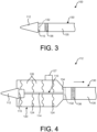
- the shoulder 115 may be configured to oppose and/or substantially abut the distal longitudinal end 134 of the stent graft cover 130, as shown in FIG. 3 , when the inner lumen 110 is in its fully retracted position.
- the inner lumen body 114 is long enough to reach from the treatment site in the vessel to the clinician.
- the inner lumen 110 can include a guide wire lumen.
- the inner lumen 110 can be made of a single material, or the inner lumen nose 112 and the inner lumen body 114 can be made of different materials.
- the inner lumen 110 can be made of flexible biocompatible materials.
- the inner lumen 110 can be made of polyurethane, polyethylene, PEBAX, nylon, or the like.
- the inner lumen nose 112 can include a radiopaque additive to provide the clinician with a visible tip when using fluoroscopy guidance to deliver the stent graft within the patient.
- the inner lumen 110 can include an electrical conductor to electrically connect the thermal cutter 132, 132' to a power source.
- the stent graft 120 may include radially expandable stents 124 (or struts) spaced apart from one another along a length of the stent graft, and graft material 126 supported by the stents 124.
- the stent graft 120 is shown in its non-expanded or collapsed configuration, generally as it would be configured within the stent graft cover 130.
- withdrawing or retracting the stent graft cover 130 relative to the stent graft 120 allows an exposed portion of the stent graft to radially expand to its expanded configuration.
- Non-stented portions 127 are portions of the stent graft 120 without stents 124 (e.g., longitudinally extending between adjacent stents and extending circumferentially around the circumference of the stent graft). Any of the non-stented portions 122 can be cut with the stent graft cutter 134 to shorten the length of the stent graft 120.
- the stent graft 120 is a single tube with regularly spaced stents 124.
- the single tube can be the main stent graft or can be an iliac limb, an aorta extender cuff, or an iliac extender cuff.
- the stent graft can be of other types and configurations.
- the stents 124 of the stent graft blank 120 are irregularly spaced.
- the stent graft 120 is a bifurcated tube.
- the stent graft 120 includes a bare spring extending distally beyond the graft material 126 to provide a radial force which engages the vessel wall and seals the stent graft at the vessel wall.
- the stent graft 120 can be any suitable tubular graft configured to expand open and be in sealing contact with tissue after being implanted at the treatment site, such as in the abdominal aorta, thoracic aorta, or other vessel.
- the stent graft 130 may be inserted into the target vessel, positioned across a lesion, and then expanded to bypass the weakened wall of the vessel, thereby preventing rupture of an aneurysm.
- the stent graft is in contact with the healthy tissue after implantation of the stent graft.
- the stent graft generally extends across the aneurysm in a vessel to divert flow through the stent graft and relieve the pressure normally applied to the weak aneurysmal wall.
- the size and configuration of the stents 124 of the stent graft 120 depend upon the size and configuration of the vessel to be treated. Some of the individual stents 124 can be connected to each other by articulated or rigid joints as long as non-stented portions are provided.
- the length of the stent graft blank 120 may be the length of the aneurysm across which the stent graft will be implanted plus an additional remainder to assure that the stent graft blank 120 is longer than the aneurysm.
- the stents 124 can be self-expanding.
- the stents 124 can be made of can be made of spring steel, stainless steel, titanium, nickel titanium alloys (Nitinol), a polymer or copolymer, a combination of these materials, or other suitable materials.
- the graft material 126 can be any woven or interlocked graft material suitable for stent grafts, such as woven polymer materials, e.g., Dacron polyester, or polytetrafluoroethylene (PTFE), or interlocked graft materials including knit, stretch, and velour materials.
- the graft material 126 includes components made of collagen, albumin, an absorbable polymer, or biocompatible fiber.
- the graft material 126 is constructed from one or more suitable plastic or non-biodegradable materials.
- the body 135 of the stent graft cover 130 may be an elongate tube which retains and/or compresses the stent graft blank 120 on the inner lumen 110 when the stent graft blank 120 is being delivered to the treatment site in the patient. The stent graft cover 130 may then be retracted to allow the exposed portion of the stent graft 120 to expand at the treatment site.
- the stent graft cover 130 may include a radiopaque marker 136 adjacent the distal longitudinal end 134 to locate the stent graft cover 130 in the vasculature and locate the stent graft cutter 132 relative to the stent graft 120.
- the body 135 of the stent graft cover 130 can be made of flexible biocompatible materials. For example, the body 135 can be made of polyurethane, polyethylene, PEBAX, nylon, or the like.
- the stent graft cutter 132 disposed within the body 135 of the stent graft cover 130 is used to cut the stent graft 120 to the desired length to form the stent graft.
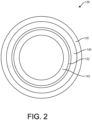
- the stent graft cutter 132 may be located on the inside circumference of the stent graft cover 130 and its distal end may be uncovered by or exposed through the distal longitudinal end 134 of the body 135, as shown in FIG. 2 .
- the stent graft cutter 132 can be molded into the stent graft cover 130 or attached to the stent graft cover 130 with an adhesive.
- the adhesive can be any biocompatible, thin, high bonding adhesive.
- an insulating layer 140 (e.g., an annular insulating layer) comprising an insulator can be placed between the stent graft cutter 132 and the body 135 of the stent graft cover 130 to protect the stent graft cover 130 from heat from the stent graft cutter 132 during cutting.
- Another insulating layer 142 can overlie a radially inner surface of the cutter 132 to protect the inner lumen 110, specifically the inner lumen body, disposed within the stent graft cover 120 radially adjacent the cutter 132.
- the insulating layer 142 may be omitted or configured to allow inner circumferential cutting by the cutter 132.
- This inner circumferential cutting of the cutter 132 may be in addition to or in combination with distal end cutting of the cutter.
- a polyxylene polymer such as Parylene can be used as the insulator of the insulating layers 140, 142.
- the insulator can also be used around the distal end of the stent graft cutter 132 to control and direct the heat from the stent graft cutter 132 distally outward from the cutter.
- the insulator can cover most of the stent graft cutter 132, such as 80 percent of the surface area of the distal end, leaving a small ring of the stent graft cutter 132 exposed, such as 20 percent of the surface area. The small ring which is exposed provides the heat to cut the stent graft 120, as explained below.
- the stent graft cutter 132 can be formed of any material which can generate sufficient heat to cut the stent graft 120, and more specifically, the graft material 126.
- the stent graft cutter 132 can be a single piece or multiple turns of wire.
- the stent graft cutter 132 is heated with a radiofrequency (RF) source, such as an RF source delivering 180 to 300 Watts, applying a radiofrequency beam to the stent graft cutter 132 from outside the patient.
- RF radiofrequency
- the stent graft cutter 132 can be made of any material that can be heated by RF, such as metal or ceramic composites.
- the stent graft cutter 132 can be made of Nitinol, stainless steel, or the like.
- the stent graft cutter 132 is heated with an electrical current source electrically connected to the stent graft cutter 132 passing an electric current through the stent graft cutter 132.
- the current source 150 FIG. 14
- the current source 150 can be provided in the handle 151 (shown schematically in FIG. 14 ), whereby electrical conductors (e.g., wires or metal bands) run along the stent graft cover 130 to the cutter 132.
- Activation of the current source 150 can be controlled by a controller 152 (e.g., microprocessor control), and the practitioner can communicate with the controller via an actuator 154 on the handle 151.
- the stent graft cutter 132 can be made of any material that can be heated with an electrical current, such as metal or ceramic composites.
- the stent graft cutter 132 can be made of Nitinol, stainless steel, nichrome, or the like, and the current source can be an electrocautery power supply.
- the combination of stent graft cutter 132 and graft material can be selected so that the stent graft cutter 132 seals the edge of the graft material when making the cut. Cutting is initiated by the energization of the stent graft cutter 132 so that it is heated to circumferentially melt the adjacent graft material that is disposed distally of the cutter.
- the stent graft delivery system 100 is delivered to the treatment site.
- a guidewire (not shown) may be used to deliver the stent graft delivery system 100 to the site.
- the practitioner retracts the stent graft cover 130 relative to the stent graft 120 and the inner lumen 110 to expose the stent graft and allow it to expand within the treatment site, as shown in FIG. 4 .
- An actuator at a handle (not shown) outside the subject may be used to retract the stent graft cover 130.
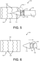
- the practitioner retracts the inner lumen 110 within the stent graft cover and relative to the stent graft, as shown in FIG. 5 .
- the tip 112 of the inner lumen 110 is retracted through the expanded stent graft 120 until it reaches the distal longitudinal end 134 of the stent graft cover 130, whereby a circumferential portion of the stent graft, more specifically a circumferential portion of the non-stented portion 127, is disposed between the shoulder 115 of the tip and the stent graft cutter 132 at the distal longitudinal end of the stent graft cover, as shown in FIGS. 7 and 8 .
- the shoulder 115 of the tip 112 may press the stent graft 120 against the distal longitudinal end of the stent graft cover 130 outside of the stent graft cover.
- the stent graft cutter 132 is then activated to circumferentially cut the stent graft 120 outside of the stent graft cover 130.
- the thermal stent graft cutter 132 is activated, such as by activating electrical current source 150 via the actuator 154, to heat the stent graft cutter. As shown in FIG.
- the expanded stent graft is released from the stent graft cover 130, and the inner lumen 110 and the stent graft cover 130 are retracted together, leaving the expanded stent graft at the treatment site within the patient.
- the stent graft cutter may be disposed within the stent graft cover.
- the stent graft cover 130' includes an internal shoulder 133 at the intersection of proximal and distal inner surfaces 137, 139, respectively, where an inner diameter at the proximal inner surface is less than an inner diameter at the distal inner surface.
- the stent graft 120 When the inner lumen tip 112' is retracted, the stent graft 120 is sandwiched between a proximal shoulder 141 (e.g., proximal longitudinal end) of the inner lumen tip and the internal shoulder 133 of the stent graft cover 130'.
- the stent graft cutter 132' e.g., an annular thermal cutter
- the stent graft cutter 132' may be disposed adjacent the proximal inner surface 139 of the stent graft cover 130' to cut a circumferential portion of the stent graft 120 disposed between the outer diameter of the inner lumen tip 112' and the proximal inner surface of the stent graft cover.
- FIG. 16 the stent graft cutter 132' (e.g., an annular thermal cutter) may be disposed adjacent the proximal inner surface 139 of the stent graft cover 130' to cut a circumferential portion
- the stent graft cutter 132' may be disposed adjacent the internal shoulder 133 of the stent graft cover 130' to cut a circumferential portion of the stent graft 120 disposed between the proximal shoulder 141 (e.g., proximal longitudinal end) of the inner lumen tip 112' and the internal shoulder.
- the stent graft cutter 132' may be disposed at other locations.
- the stent graft delivery system includes a safety system configured to allow activation of the stent graft cutter only when the stent graft is suitably sandwiched between the inner lumen tip and the distal end of the stent graft cover to inhibit inadvertent activation of the cutter and provide for proper cutting of the stent graft.
- a safety system is incorporated in the illustrated stent graft delivery system 100.
- the safety system may be incorporated in other stent graft delivery systems utilizing other stent graft cutting arrangement and configurations.
- the safety system can be incorporated into the stent graft delivery system described below. It is understood that the safety system may have other configurations and/or designs configured to determine when the stent graft is suitably sandwiched between the inner lumen tip and the distal end of the stent graft cover.
- the safety system includes at least one sensor 160 (e.g., a proximity sensor or pressure sensor) on either or both of the inner lumen tip 112 and the distal longitudinal end 134 of the stent graft cover 130.
- the sensor is mounted on or in (broadly, coupled to) the inner lumen tip 112.
- the sensor 160 may be in communication with (e.g., wired or wireless) the controller 152, which can be housed in the handle.
- the controller 152 may be configured to receive the signal from the sensor 160 and determine whether the stent graft 120 is suitably sandwiched between the inner lumen tip 112 and the distal longitudinal end 134 of the stent graft cover 130 based on the received signal. If the controller 152 determines the stent graft 120 is suitably sandwiched between the inner lumen tip 112 (e.g., the shoulder 115) and the distal longitudinal end 134 of the stent graft cover 130 based on the received signal, then the controller may be configured to allow activation of the stent graft cutter 132.
- the stent 160 is a proximity sensor configured to provide a signal to the controller 152 indicative of the proximity of the sensor and the inner lumen tip 112 (e.g., the shoulder 115 of the inner lumen tip) to the distal longitudinal end 134 of the stent graft cover 130 (e.g., the stent graft cutter 132).
- the signal generated by the sensor 160 and received by the controller 152 is indicative of the stent graft 120 being suitable for cutting, for example, the stent graft is suitably sandwiched between the inner lumen tip 112 and the distal longitudinal end 134 of the stent graft cover 130 or the inner lumen tip is suitably disposed within the stent graft cover 130.
- the stent 160 is a pressure sensor configured to provide a signal to the controller 152 indicative of the inner lumen tip 112 (e.g., the shoulder 115 of the inner lumen tip) applying pressure to the distal longitudinal end 134 of the stent graft cover 130 (e.g., the stent graft cutter 132).
- the signal generated by the sensor 160 and received by the controller 152 is indicative of the stent graft 120 being suitably sandwiched between the inner lumen tip and the distal end of the stent graft cover.
- the sensor 160 may be an impedance sensor or another sensor.
- the senor 160 may be disposed adjacent the proximal shoulder 141 (e.g., proximal longitudinal end) of the inner lumen tip 112'.
- the operation of the sensor 160 may be substantially the same as described above.
- the sensor 160 may be configured to indicate to the controller 152 when the inner lumen (e.g., inner lumen tip 112') is suitably disposed within the stent graft cover 130' to allow for suitable cutting.
- the stent graft 120 may indicate to the controller 152 when the stent graft 120 is sandwiched between the inner lumen tip 112' and the inner surface (e.g., one of the inner surfaces 139, 137) of the stent graft cover 130'.
- the inner surface e.g., one of the inner surfaces 139, 137
- the safety system may be incorporated in other stent graft delivery systems utilizing other stent graft cutting arrangement and configurations.
- the safety system can be incorporated into the stent graft delivery system described below. It is understood that the safety system may have other configurations and/or designs configured to determine when the stent graft is suitably sandwiched between the inner lumen tip and the distal end of the stent graft cover.
- FIG. 19 A suitable diagram of control system for at least one embodiment of the stent graft delivery system is shown in FIG. 19 .
- the stent graft delivery system 200 includes an inner lumen 210, a stent graft 220 positionable over the inner lumen, and a stent graft cover 230 slidably positionable over the stent graft 220.
- FIG. 1 A stent graft delivery system 200 includes an inner lumen 210, a stent graft 220 positionable over the inner lumen, and a stent graft cover 230 slidably positionable over the stent graft 220.
- the stent graft delivery system 200 is shown with the stent graft cover 230 retracted to expose and allow expansion of the stent graft 220, the inner lumen 210 in a retracted configuration, and the inner lumen tip 212 generally abutting a distal longitudinal end 234 of the stent graft cover 230 (transparent), and the proximal longitudinal portion of the inner lumen tip being show in section.
- the stent graft delivery system may be the same as the stent graft delivery system described above, with the same or like component being indicated by the corresponding reference numerals plus 100.
- the stent graft cutter 232 of the present stent graft delivery system 200 is located on the inner lumen tip 212 rather than at the distal longitudinal end 234 of the stent graft cover 230.
- the illustrated stent graft cutter 232 is a thermal cutter which produces high temperature heat to cut the stent graft 220.
- the thermal cutter 232 general opposes the distal longitudinal end 234 of the stent graft cover 230.
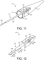
- the thermal cutter 232 may be at the shoulder 215 of the inner lumen tip 212, which may be at the proximal end of the inner lumen tip, such as shown in FIGS. 9-13 , or at an intermediate longitudinal location, such as shown in the first embodiment of the stent graft delivery system described above.
- the illustrated cutter 232 may include an annular cutter body within the inner lumen tip 212. As shown in FIG. 10 , an annular layer 233 of insulation may be disposed radially between the cutter 232 and the inner lumen tip 212. Positive and negative terminals 280, 282 may extend longitudinally from the annular cutter body and/or may be electrically connected to respective conductors within the inner lumen tip. As an example, referring to FIG.
- the elongate body 214 of the inner lumen 210 may include a first conductor 284 electrically connected to the negative terminal 282, such as by a jumper 286 or in other ways, and a second conductor 288 electrically connected to the positive terminal 280, such as by a jumper 290 or in other ways.
- the proximal ends of the first and second conductors 284, 288 can be electrically connected to the electrical current source 150, whereby current is selectively delivered to the thermal cutter 232 to activate cutting.
- the stent graft 220 may be selectively cut using the cutter 232 in a manner similar to the first embodiment of the stent delivery system 100 described above.
- the inner lumen 210 is retracted to bring the inner lumen tip 212 to the distal longitudinal end 234 of the stent graft cover 230.
- the cutter 232 may be activated by the practitioner to cut the stent graft.
- the stent graft delivery system 200 may include the safety system which is employed in a similar manner as described above.
- the thermal cutter may be disposed at other locations on the inner lumen.
- a thermal cutter 232' is proximal of the shoulder 215 of the inner lumen tip 212', such as on the body 235' of the inner lumen or on a proximal portion of the inner lumen tip.
- a sensor 260 may be disposed on the stent graft cover 230'. The sensor 260 is configured to be operated and used in the same manner as the sensor 160 described above.
- the thermal cutter 232" may be at the proximal shoulder 241 (e.g., proximal longitudinal end) of the inner lumen tip 212".
- This embodiment may be similar in construction and operation to the embodiment of FIGS. 15 and 16 , except the thermal cutter 232" is on the inner lumen tip 212", adjacent the proximal shoulder 241, and the sensor 260' may be on the stent graft cover 230" adjacent the internal shoulder 233.
- the inner lumen 310 may be incorporated in any of the above-described stent graft delivery systems.
- the inner lumen 310 includes an elongate body 314 and an inner lumen tip 312 at a distal end of the elongate body.
- the inner lumen tip 312 may include the cutter or the cutter may be at other locations.
- the elongate body 314 may include an outer body portion 314A and an inner body portion 314B received in and extending along the outer body portion.
- the outer body portion 314A may define one or more openings 315 at a distal end portion thereof, such as within a space defined by a proximal end portion of the inner lumen tip 312.
- a plenum 317 for fluid (e.g., gas or liquid) defined by the elongate body 314 may be in fluid communication with the openings 315.
- the plenum 317 may be defined by the annular space between the inner body portion 314B and the outer body portion 314A.
- a proximal end of the plenum 317 may be configured to be in fluid communication with a source of fluid (e.g., gas or liquid).
- the source of fluid may be carbon dioxide or other gas soluble in blood or liquid.
- the gas for example, escaping the openings 315 forces environmental fluid out of the immediate space around the area where the stent graft is clamped to facilitate a rapid temperature increase and sustained temperatures needed to complete the trimming operation.
- the described techniques may be implemented in hardware, software, firmware, or any combination thereof. If implemented in software, the functions may be stored as one or more instructions or code on a computer-readable medium and executed by a hardware-based processing unit.
- Computer-readable media may include non-transitory computer-readable media, which corresponds to a tangible medium such as data storage media (e.g., RAM, ROM, EEPROM, flash memory, or any other medium that can be used to store desired program code in the form of instructions or data structures and that can be accessed by a computer).
- controllers such as one or more digital signal processors (DSPs), general purpose microprocessors, application specific integrated circuits (ASICs), field programmable logic arrays (FPGAs), or other equivalent integrated or discrete logic circuitry.
- DSPs digital signal processors
- ASICs application specific integrated circuits
- FPGAs field programmable logic arrays
- controller may refer to any of the foregoing structure or any other physical structure suitable for implementation of the described techniques. Also, the techniques could be fully implemented in one or more circuits or logic elements.
- a stent graft delivery system comprising:
- Clause 3 The stent graft delivery system set forth in any preceding clause, and in particular clause 2, wherein the inner lumen is configured to be retracted through the expanded longitudinal portion of the stent graft exposed outside the stent graft cover to a retracted position in which a circumferential portion of the stent graft cover is sandwiched between the inner lumen tip and the distal longitudinal end of the stent graft cover.
- Clause 4 The stent graft delivery system set forth in any preceding clause, and in particular in clause 2, wherein the inner lumen includes a proximally-facing shoulder, wherein the inner lumen is configured to be retracted through the expanded longitudinal portion of the stent graft exposed outside the stent graft cover to a retracted position in which a circumferential portion of the stent graft cover is sandwiched between the proximally-facing shoulder of the inner lumen tip and the distal longitudinal end of the stent graft cover.
- stent graft delivery system set forth in any preceding clause, and in particular in clause 3, further comprising a safety system including a sensor configured to detect a parameter relating to a relationship between the inner lumen tip and the distal longitudinal end of the stent graft cover.
- Clause 7 The stent graft delivery system set forth in any preceding clause, and in particular in clause 6, wherein the sensor is coupled to at least one of the inner lumen tip and the stent graft cover.
- Clause 8 The stent graft delivery system set forth in any preceding clause, and in particular in clause 7, wherein the safety system further includes a controller in communication with the sensor, wherein the controller is configured to receive the signal from the sensor and determine whether the stent graft is suitably sandwiched between the inner lumen tip and the distal longitudinal end of the stent graft cover based on the received signal.
- a stent graft delivery system comprising:
- Clause 13 The stent graft delivery system set forth in clause 12, wherein the longitudinal portion of the stent graft exposed outside the stent graft cover is configured to radially expand.
- Clause 14 The stent graft delivery system set forth in clause 12 or 13, wherein the inner lumen is configured to be retracted through the expanded longitudinal portion of the stent graft exposed outside the stent graft cover to a retracted position in which a circumferential portion of the stent graft cover is sandwiched between the thermal stent graft cutter on the inner lumen tip and the distal longitudinal end of the stent graft cover.
- Clause 15 The stent graft delivery system set forth in any of clauses 12 to 14, and in particular in clause 14, wherein the inner lumen includes a proximally-facing shoulder, wherein the thermal stent graft cutter is coupled to the proximally-facing shoulder.
- Clause 16 The stent graft delivery system set forth in clause in any of clauses 12 to 15, and in particular 14, further comprising a safety system including a sensor configured to detect a parameter relating to a relationship between the inner lumen tip and the distal longitudinal end of the stent graft cover.
- Clause 17 The stent graft delivery system set forth in clause 16, wherein the sensor is coupled to at least one of the inner lumen tip and the stent graft cover.
- Clause 18 The stent graft delivery system set forth in clause 16 or 17, wherein the safety system further includes a controller in communication with the sensor, wherein the controller is configured to receive the signal from the sensor and determine whether the stent graft is suitably sandwiched between the inner lumen tip and the distal longitudinal end of the stent graft cover based on the received signal.
- a method of delivering a stent graft to a treatment site within a subject comprising:
Landscapes
- Health & Medical Sciences (AREA)
- Engineering & Computer Science (AREA)
- Biomedical Technology (AREA)
- Heart & Thoracic Surgery (AREA)
- Oral & Maxillofacial Surgery (AREA)
- Transplantation (AREA)
- Cardiology (AREA)
- Vascular Medicine (AREA)
- Life Sciences & Earth Sciences (AREA)
- Animal Behavior & Ethology (AREA)
- General Health & Medical Sciences (AREA)
- Public Health (AREA)
- Veterinary Medicine (AREA)
- Pulmonology (AREA)
- Gastroenterology & Hepatology (AREA)
- Prostheses (AREA)
Applications Claiming Priority (2)
| Application Number | Priority Date | Filing Date | Title |
|---|---|---|---|
| US17/212,689 US12115090B2 (en) | 2021-03-25 | 2021-03-25 | Stent graft delivery system including stent graft cutter |
| EP22163185.6A EP4062871B1 (de) | 2021-03-25 | 2022-03-21 | Stent-graft-einführungssystem mit stent-graft-schneider |
Related Parent Applications (2)
| Application Number | Title | Priority Date | Filing Date |
|---|---|---|---|
| EP22163185.6A Division-Into EP4062871B1 (de) | 2021-03-25 | 2022-03-21 | Stent-graft-einführungssystem mit stent-graft-schneider |
| EP22163185.6A Division EP4062871B1 (de) | 2021-03-25 | 2022-03-21 | Stent-graft-einführungssystem mit stent-graft-schneider |
Publications (2)
| Publication Number | Publication Date |
|---|---|
| EP4477191A2 true EP4477191A2 (de) | 2024-12-18 |
| EP4477191A3 EP4477191A3 (de) | 2025-03-26 |
Family
ID=80928570
Family Applications (2)
| Application Number | Title | Priority Date | Filing Date |
|---|---|---|---|
| EP24210880.1A Pending EP4477191A3 (de) | 2021-03-25 | 2022-03-21 | Stentgrafteinführungssystem mit stentgraft-schneidevorrichtung |
| EP22163185.6A Active EP4062871B1 (de) | 2021-03-25 | 2022-03-21 | Stent-graft-einführungssystem mit stent-graft-schneider |
Family Applications After (1)
| Application Number | Title | Priority Date | Filing Date |
|---|---|---|---|
| EP22163185.6A Active EP4062871B1 (de) | 2021-03-25 | 2022-03-21 | Stent-graft-einführungssystem mit stent-graft-schneider |
Country Status (3)
| Country | Link |
|---|---|
| US (2) | US12115090B2 (de) |
| EP (2) | EP4477191A3 (de) |
| CN (1) | CN115120396A (de) |
Families Citing this family (4)
| Publication number | Priority date | Publication date | Assignee | Title |
|---|---|---|---|---|
| CN114025710A (zh) * | 2019-12-06 | 2022-02-08 | 爱德华兹生命科学公司 | 用于在程序期间测量实时瓣膜直径的挠曲传感器 |
| US12471926B2 (en) | 2023-02-22 | 2025-11-18 | eLum Technologies, Inc. | Systems and methods for customizable flow diverter implants |
| US12502177B2 (en) | 2023-02-22 | 2025-12-23 | eLum Technologies, Inc. | Systems and methods for customizable flow diverter implants |
| CN119894467B (zh) * | 2023-08-22 | 2026-05-12 | 艾露姆技术股份有限公司 | 用于可定制的分流器植入物的系统和方法 |
Family Cites Families (8)
| Publication number | Priority date | Publication date | Assignee | Title |
|---|---|---|---|---|
| WO2002069813A2 (en) * | 2001-02-05 | 2002-09-12 | A-Med Systems, Inc. | Anastomosis system and related methods |
| US20030135266A1 (en) * | 2001-12-03 | 2003-07-17 | Xtent, Inc. | Apparatus and methods for delivery of multiple distributed stents |
| WO2007124289A2 (en) * | 2006-04-21 | 2007-11-01 | Xtent, Inc. | Devices and methods for controlling and counting interventional elements |
| US20090264987A1 (en) | 2008-04-18 | 2009-10-22 | Medtronic Vascular, Inc. | Stent Graft Delivery System and Method of Use |
| US20100125323A1 (en) | 2008-11-14 | 2010-05-20 | Medtronic Vascular, Inc. | Coil Stent Delivery System and Method of Use |
| US20120253471A1 (en) | 2011-04-04 | 2012-10-04 | Medtronic Vascular, Inc. | Variable Length Airway Stent Graft With One-Way Valves |
| US10159819B2 (en) | 2014-04-24 | 2018-12-25 | Medtronic Vascular Galway | Control module for delivery systems |
| WO2018111758A1 (en) * | 2016-12-12 | 2018-06-21 | Boston Scientific Scimed, Inc. | Stent trimming devices |
-
2021
- 2021-03-25 US US17/212,689 patent/US12115090B2/en active Active
-
2022
- 2022-02-15 CN CN202210138635.2A patent/CN115120396A/zh active Pending
- 2022-03-21 EP EP24210880.1A patent/EP4477191A3/de active Pending
- 2022-03-21 EP EP22163185.6A patent/EP4062871B1/de active Active
-
2024
- 2024-09-09 US US18/829,058 patent/US20240423821A1/en active Pending
Also Published As
| Publication number | Publication date |
|---|---|
| CN115120396A (zh) | 2022-09-30 |
| US20220304837A1 (en) | 2022-09-29 |
| EP4062871A1 (de) | 2022-09-28 |
| US20240423821A1 (en) | 2024-12-26 |
| EP4062871B1 (de) | 2024-12-25 |
| EP4477191A3 (de) | 2025-03-26 |
| US12115090B2 (en) | 2024-10-15 |
Similar Documents
| Publication | Publication Date | Title |
|---|---|---|
| EP4062871B1 (de) | Stent-graft-einführungssystem mit stent-graft-schneider | |
| EP1970027B1 (de) | Fluoroskopischer Gefäßmarker | |
| US20090264988A1 (en) | Stent Graft Delivery System Including Support for Fenestration in Situ and a Mechanism for Modeling | |
| EP1621160B1 (de) | Einführvorrichtung mit einer niedrigen Entfaltungskraft | |
| EP2614795B1 (de) | Ballonexpandierbare bzw. selbstexpandierende Prothese | |
| US20100179632A1 (en) | Robotic Fenestration Device Having Impedance Measurement | |
| US8206430B2 (en) | Endolumenal sealant delivery apparatus and methods | |
| US9211183B2 (en) | Thoracic stent graft with guide arrangement | |
| EP1637177A1 (de) | Vorübergehender verweilkatheter und stentimplantat | |
| US20070118099A1 (en) | Method and apparatus for endovascular graft cutting | |
| US20080234717A1 (en) | Helical Screw Puncture Tip | |
| US20110066221A1 (en) | Hybrid intraluminal device | |
| US20120065725A1 (en) | Prosthesis for antegrade deployment | |
| JP7182115B2 (ja) | 管状医療器具 | |
| US20090264987A1 (en) | Stent Graft Delivery System and Method of Use | |
| US20250222242A1 (en) | Systems and methods for treating aortic aneurysms | |
| US9486346B2 (en) | Balloon expandable stent graft and apparatus and method for expanding a balloon expandable stent graft | |
| JP2008509724A (ja) | 押出成形被覆を設けたステント | |
| EP2799038B1 (de) | Endoluminales Prothesenabgabesystem | |
| US11826089B2 (en) | Compression stent device and methods | |
| US10238395B2 (en) | Arterial wall compression stent | |
| EP1965731B1 (de) | Endoprothese und verfahren zur verbindung eines stützgerüsts mit gewebtem prothesenmaterial |
Legal Events
| Date | Code | Title | Description |
|---|---|---|---|
| PUAI | Public reference made under article 153(3) epc to a published international application that has entered the european phase |
Free format text: ORIGINAL CODE: 0009012 |
|
| STAA | Information on the status of an ep patent application or granted ep patent |
Free format text: STATUS: REQUEST FOR EXAMINATION WAS MADE |
|
| 17P | Request for examination filed |
Effective date: 20241105 |
|
| AC | Divisional application: reference to earlier application |
Ref document number: 4062871 Country of ref document: EP Kind code of ref document: P |
|
| AK | Designated contracting states |
Kind code of ref document: A2 Designated state(s): AL AT BE BG CH CY CZ DE DK EE ES FI FR GB GR HR HU IE IS IT LI LT LU LV MC MK MT NL NO PL PT RO RS SE SI SK SM TR |
|
| REG | Reference to a national code |
Ref country code: DE Ref legal event code: R079 Free format text: PREVIOUS MAIN CLASS: A61F0002966000 Ipc: A61F0002070000 |
|
| PUAL | Search report despatched |
Free format text: ORIGINAL CODE: 0009013 |
|
| AK | Designated contracting states |
Kind code of ref document: A3 Designated state(s): AL AT BE BG CH CY CZ DE DK EE ES FI FR GB GR HR HU IE IS IT LI LT LU LV MC MK MT NL NO PL PT RO RS SE SI SK SM TR |
|
| RIC1 | Information provided on ipc code assigned before grant |
Ipc: A61F 2/966 20130101ALI20250214BHEP Ipc: A61F 2/07 20130101AFI20250214BHEP |
|
| GRAP | Despatch of communication of intention to grant a patent |
Free format text: ORIGINAL CODE: EPIDOSNIGR1 |
|
| STAA | Information on the status of an ep patent application or granted ep patent |
Free format text: STATUS: GRANT OF PATENT IS INTENDED |
|
| INTG | Intention to grant announced |
Effective date: 20260120 |
|
| GRAS | Grant fee paid |
Free format text: ORIGINAL CODE: EPIDOSNIGR3 |
|
| GRAA | (expected) grant |
Free format text: ORIGINAL CODE: 0009210 |
|
| STAA | Information on the status of an ep patent application or granted ep patent |
Free format text: STATUS: THE PATENT HAS BEEN GRANTED |