EP4477152A1 - Ultrasonic diagnostic device - Google Patents
Ultrasonic diagnostic device Download PDFInfo
- Publication number
- EP4477152A1 EP4477152A1 EP22926047.6A EP22926047A EP4477152A1 EP 4477152 A1 EP4477152 A1 EP 4477152A1 EP 22926047 A EP22926047 A EP 22926047A EP 4477152 A1 EP4477152 A1 EP 4477152A1
- Authority
- EP
- European Patent Office
- Prior art keywords
- probe
- inclination angle
- image
- diagnostic
- living body
- Prior art date
- Legal status (The legal status is an assumption and is not a legal conclusion. Google has not performed a legal analysis and makes no representation as to the accuracy of the status listed.)
- Pending
Links
Images





Classifications
-
- A—HUMAN NECESSITIES
- A61—MEDICAL OR VETERINARY SCIENCE; HYGIENE
- A61B—DIAGNOSIS; SURGERY; IDENTIFICATION
- A61B8/00—Diagnosis using ultrasonic, sonic or infrasonic waves
- A61B8/46—Ultrasonic, sonic or infrasonic diagnostic devices with special arrangements for interfacing with the operator or the patient
- A61B8/461—Displaying means of special interest
-
- A—HUMAN NECESSITIES
- A61—MEDICAL OR VETERINARY SCIENCE; HYGIENE
- A61B—DIAGNOSIS; SURGERY; IDENTIFICATION
- A61B8/00—Diagnosis using ultrasonic, sonic or infrasonic waves
-
- A—HUMAN NECESSITIES
- A61—MEDICAL OR VETERINARY SCIENCE; HYGIENE
- A61B—DIAGNOSIS; SURGERY; IDENTIFICATION
- A61B8/00—Diagnosis using ultrasonic, sonic or infrasonic waves
- A61B8/13—Tomography
- A61B8/14—Echo-tomography
-
- A—HUMAN NECESSITIES
- A61—MEDICAL OR VETERINARY SCIENCE; HYGIENE
- A61B—DIAGNOSIS; SURGERY; IDENTIFICATION
- A61B8/00—Diagnosis using ultrasonic, sonic or infrasonic waves
- A61B8/42—Details of probe positioning or probe attachment to the patient
-
- A—HUMAN NECESSITIES
- A61—MEDICAL OR VETERINARY SCIENCE; HYGIENE
- A61B—DIAGNOSIS; SURGERY; IDENTIFICATION
- A61B8/00—Diagnosis using ultrasonic, sonic or infrasonic waves
- A61B8/42—Details of probe positioning or probe attachment to the patient
- A61B8/4245—Details of probe positioning or probe attachment to the patient involving determining the position of the probe, e.g. with respect to an external reference frame or to the patient
- A61B8/4254—Details of probe positioning or probe attachment to the patient involving determining the position of the probe, e.g. with respect to an external reference frame or to the patient using sensors mounted on the probe
-
- A—HUMAN NECESSITIES
- A61—MEDICAL OR VETERINARY SCIENCE; HYGIENE
- A61B—DIAGNOSIS; SURGERY; IDENTIFICATION
- A61B8/00—Diagnosis using ultrasonic, sonic or infrasonic waves
- A61B8/44—Constructional features of the ultrasonic, sonic or infrasonic diagnostic device
- A61B8/4444—Constructional features of the ultrasonic, sonic or infrasonic diagnostic device related to the probe
-
- A—HUMAN NECESSITIES
- A61—MEDICAL OR VETERINARY SCIENCE; HYGIENE
- A61B—DIAGNOSIS; SURGERY; IDENTIFICATION
- A61B8/00—Diagnosis using ultrasonic, sonic or infrasonic waves
- A61B8/46—Ultrasonic, sonic or infrasonic diagnostic devices with special arrangements for interfacing with the operator or the patient
- A61B8/461—Displaying means of special interest
- A61B8/463—Displaying means of special interest characterised by displaying multiple images or images and diagnostic data on one display
-
- G—PHYSICS
- G01—MEASURING; TESTING
- G01C—MEASURING DISTANCES, LEVELS OR BEARINGS; SURVEYING; NAVIGATION; GYROSCOPIC INSTRUMENTS; PHOTOGRAMMETRY OR VIDEOGRAMMETRY
- G01C9/00—Measuring inclination, e.g. by clinometers, by levels
- G01C9/02—Details
-
- G—PHYSICS
- G01—MEASURING; TESTING
- G01S—RADIO DIRECTION-FINDING; RADIO NAVIGATION; DETERMINING DISTANCE OR VELOCITY BY USE OF RADIO WAVES; LOCATING OR PRESENCE-DETECTING BY USE OF THE REFLECTION OR RERADIATION OF RADIO WAVES; ANALOGOUS ARRANGEMENTS USING OTHER WAVES
- G01S15/00—Systems using the reflection or reradiation of acoustic waves, e.g. sonar systems
- G01S15/88—Sonar systems specially adapted for specific applications
- G01S15/89—Sonar systems specially adapted for specific applications for mapping or imaging
- G01S15/8906—Short-range imaging systems; Acoustic microscope systems using pulse-echo techniques
- G01S15/8934—Short-range imaging systems; Acoustic microscope systems using pulse-echo techniques using a dynamic transducer configuration
- G01S15/8936—Short-range imaging systems; Acoustic microscope systems using pulse-echo techniques using a dynamic transducer configuration using transducers mounted for mechanical movement in three dimensions
-
- G—PHYSICS
- G01—MEASURING; TESTING
- G01S—RADIO DIRECTION-FINDING; RADIO NAVIGATION; DETERMINING DISTANCE OR VELOCITY BY USE OF RADIO WAVES; LOCATING OR PRESENCE-DETECTING BY USE OF THE REFLECTION OR RERADIATION OF RADIO WAVES; ANALOGOUS ARRANGEMENTS USING OTHER WAVES
- G01S15/00—Systems using the reflection or reradiation of acoustic waves, e.g. sonar systems
- G01S15/88—Sonar systems specially adapted for specific applications
- G01S15/89—Sonar systems specially adapted for specific applications for mapping or imaging
- G01S15/8906—Short-range imaging systems; Acoustic microscope systems using pulse-echo techniques
- G01S15/899—Combination of imaging systems with ancillary equipment
-
- G—PHYSICS
- G01—MEASURING; TESTING
- G01S—RADIO DIRECTION-FINDING; RADIO NAVIGATION; DETERMINING DISTANCE OR VELOCITY BY USE OF RADIO WAVES; LOCATING OR PRESENCE-DETECTING BY USE OF THE REFLECTION OR RERADIATION OF RADIO WAVES; ANALOGOUS ARRANGEMENTS USING OTHER WAVES
- G01S7/00—Details of systems according to groups G01S13/00, G01S15/00, G01S17/00
- G01S7/52—Details of systems according to groups G01S13/00, G01S15/00, G01S17/00 of systems according to group G01S15/00
- G01S7/52017—Details of systems according to groups G01S13/00, G01S15/00, G01S17/00 of systems according to group G01S15/00 particularly adapted to short-range imaging
- G01S7/52053—Display arrangements
- G01S7/52057—Cathode ray tube displays
-
- G—PHYSICS
- G01—MEASURING; TESTING
- G01S—RADIO DIRECTION-FINDING; RADIO NAVIGATION; DETERMINING DISTANCE OR VELOCITY BY USE OF RADIO WAVES; LOCATING OR PRESENCE-DETECTING BY USE OF THE REFLECTION OR RERADIATION OF RADIO WAVES; ANALOGOUS ARRANGEMENTS USING OTHER WAVES
- G01S7/00—Details of systems according to groups G01S13/00, G01S15/00, G01S17/00
- G01S7/52—Details of systems according to groups G01S13/00, G01S15/00, G01S17/00 of systems according to group G01S15/00
- G01S7/52017—Details of systems according to groups G01S13/00, G01S15/00, G01S17/00 of systems according to group G01S15/00 particularly adapted to short-range imaging
- G01S7/52053—Display arrangements
- G01S7/52057—Cathode ray tube displays
- G01S7/52073—Production of cursor lines, markers or indicia by electronic means
-
- G—PHYSICS
- G01—MEASURING; TESTING
- G01S—RADIO DIRECTION-FINDING; RADIO NAVIGATION; DETERMINING DISTANCE OR VELOCITY BY USE OF RADIO WAVES; LOCATING OR PRESENCE-DETECTING BY USE OF THE REFLECTION OR RERADIATION OF RADIO WAVES; ANALOGOUS ARRANGEMENTS USING OTHER WAVES
- G01S7/00—Details of systems according to groups G01S13/00, G01S15/00, G01S17/00
- G01S7/52—Details of systems according to groups G01S13/00, G01S15/00, G01S17/00 of systems according to group G01S15/00
- G01S7/52017—Details of systems according to groups G01S13/00, G01S15/00, G01S17/00 of systems according to group G01S15/00 particularly adapted to short-range imaging
- G01S7/52053—Display arrangements
- G01S7/52057—Cathode ray tube displays
- G01S7/52074—Composite displays, e.g. split-screen displays; Combination of multiple images or of images and alphanumeric tabular information
-
- G—PHYSICS
- G01—MEASURING; TESTING
- G01S—RADIO DIRECTION-FINDING; RADIO NAVIGATION; DETERMINING DISTANCE OR VELOCITY BY USE OF RADIO WAVES; LOCATING OR PRESENCE-DETECTING BY USE OF THE REFLECTION OR RERADIATION OF RADIO WAVES; ANALOGOUS ARRANGEMENTS USING OTHER WAVES
- G01S7/00—Details of systems according to groups G01S13/00, G01S15/00, G01S17/00
- G01S7/52—Details of systems according to groups G01S13/00, G01S15/00, G01S17/00 of systems according to group G01S15/00
- G01S7/52017—Details of systems according to groups G01S13/00, G01S15/00, G01S17/00 of systems according to group G01S15/00 particularly adapted to short-range imaging
- G01S7/52079—Constructional features
-
- G—PHYSICS
- G01—MEASURING; TESTING
- G01S—RADIO DIRECTION-FINDING; RADIO NAVIGATION; DETERMINING DISTANCE OR VELOCITY BY USE OF RADIO WAVES; LOCATING OR PRESENCE-DETECTING BY USE OF THE REFLECTION OR RERADIATION OF RADIO WAVES; ANALOGOUS ARRANGEMENTS USING OTHER WAVES
- G01S7/00—Details of systems according to groups G01S13/00, G01S15/00, G01S17/00
- G01S7/52—Details of systems according to groups G01S13/00, G01S15/00, G01S17/00 of systems according to group G01S15/00
- G01S7/52017—Details of systems according to groups G01S13/00, G01S15/00, G01S17/00 of systems according to group G01S15/00 particularly adapted to short-range imaging
- G01S7/52085—Details related to the ultrasound signal acquisition, e.g. scan sequences
-
- A—HUMAN NECESSITIES
- A61—MEDICAL OR VETERINARY SCIENCE; HYGIENE
- A61B—DIAGNOSIS; SURGERY; IDENTIFICATION
- A61B8/00—Diagnosis using ultrasonic, sonic or infrasonic waves
- A61B8/42—Details of probe positioning or probe attachment to the patient
- A61B8/4245—Details of probe positioning or probe attachment to the patient involving determining the position of the probe, e.g. with respect to an external reference frame or to the patient
- A61B8/4263—Details of probe positioning or probe attachment to the patient involving determining the position of the probe, e.g. with respect to an external reference frame or to the patient using sensors not mounted on the probe, e.g. mounted on an external reference frame
-
- A—HUMAN NECESSITIES
- A61—MEDICAL OR VETERINARY SCIENCE; HYGIENE
- A61B—DIAGNOSIS; SURGERY; IDENTIFICATION
- A61B8/00—Diagnosis using ultrasonic, sonic or infrasonic waves
- A61B8/42—Details of probe positioning or probe attachment to the patient
- A61B8/4272—Details of probe positioning or probe attachment to the patient involving the acoustic interface between the transducer and the tissue
-
- A—HUMAN NECESSITIES
- A61—MEDICAL OR VETERINARY SCIENCE; HYGIENE
- A61B—DIAGNOSIS; SURGERY; IDENTIFICATION
- A61B8/00—Diagnosis using ultrasonic, sonic or infrasonic waves
- A61B8/44—Constructional features of the ultrasonic, sonic or infrasonic diagnostic device
- A61B8/4444—Constructional features of the ultrasonic, sonic or infrasonic diagnostic device related to the probe
- A61B8/4455—Features of the external shape of the probe, e.g. ergonomic aspects
-
- A—HUMAN NECESSITIES
- A61—MEDICAL OR VETERINARY SCIENCE; HYGIENE
- A61B—DIAGNOSIS; SURGERY; IDENTIFICATION
- A61B8/00—Diagnosis using ultrasonic, sonic or infrasonic waves
- A61B8/46—Ultrasonic, sonic or infrasonic diagnostic devices with special arrangements for interfacing with the operator or the patient
-
- A—HUMAN NECESSITIES
- A61—MEDICAL OR VETERINARY SCIENCE; HYGIENE
- A61B—DIAGNOSIS; SURGERY; IDENTIFICATION
- A61B8/00—Diagnosis using ultrasonic, sonic or infrasonic waves
- A61B8/54—Control of the diagnostic device
-
- G—PHYSICS
- G01—MEASURING; TESTING
- G01B—MEASURING LENGTH, THICKNESS OR SIMILAR LINEAR DIMENSIONS; MEASURING ANGLES; MEASURING AREAS; MEASURING IRREGULARITIES OF SURFACES OR CONTOURS
- G01B11/00—Measuring arrangements characterised by the use of optical techniques
- G01B11/002—Measuring arrangements characterised by the use of optical techniques for measuring two or more coordinates
Definitions
- the present disclosure relates to an ultrasound diagnostic device.
- This application claims the benefit of priority of Japanese Patent Application No. 2022-19567 filed on February 10, 2022 , and contents thereof are incorporated herein.
- Patent Literature 1 in order to appropriately perform the ultrasonic wave flaw detection for the pipe, an ultrasonic wave is radiated onto the surface of the pipe in a direction perpendicular to the surface of the pipe. That is, the ultrasonic transducer that emits the ultrasonic wave is arranged perpendicularly to the surface of the pipe.
- an object to be subjected to the ultrasonic wave flaw detection is a pipe.
- the pipe is a rigid body, and hence does not deform at the time of the ultrasonic wave flaw detection.
- the ultrasonic wave flaw detection for the pipe is performed while maintaining a state in which the ultrasonic transducer is arranged perpendicularly to the surface of the pipe.
- the ultrasound diagnostic device may further include a storage unit configured to store in advance diagnostic reference information in which an allowable range of the position of the probe for diagnosing a specific organ in the living body and an allowable range of the inclination angle of the probe for diagnosing the specific organ are associated with each other.
- the probe specifying unit may be configured to output a predetermined alarm in at least one of a case in which a current position of the probe is out of the allowable range of the position of the probe indicated by the diagnostic reference information and a case in which a current inclination angle of the probe is out of the allowable range of the inclination angle of the probe indicated by the diagnostic reference information, at the time of diagnosing the specific organ.
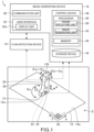
- FIG. 1 is a schematic view for illustrating a configuration of an ultrasound diagnostic device 1 according to a first embodiment.
- the ultrasound diagnostic device 1 of the first embodiment diagnoses, for example, a living body 2 such as a human body as a diagnosis object, and performs ultrasound diagnostic on the diagnosis object.
- the diagnosis object is not limited to the living body 2, and may be any object.
- the ultrasound diagnostic device 1 includes a sheet material 10, a probe 12, a flaw detection device 14, and an image generating device 16.
- the sheet material 10 is made of a material that transmits an ultrasonic wave, and is formed into a flexible sheet shape.
- a shape of a surface 10a of the sheet material 10 is a quadrangular shape, but is not limited to the quadrangular shape, and may be any shape.
- the sheet material 10 is capable of being attached to the surface of the living body 2. For example, a contact medium for transmitting an ultrasonic wave is applied to a surface of an abdomen of the living body 2, and the sheet material 10 is attached onto the contact medium.
- coordinate data indicating the position within the surface 10a of the sheet material 10 is encrypted.
- a two-dimensional code 20 arranged at a predetermined one corner (for example, a right lower corner in the sheet material 10 of FIG. 1 ) of the sheet material 10 is set as a two-dimensional code 20 at a reference position.
- Coordinate data of "m, n" is encrypted on a two-dimensional code 20 located at an m-th position in the X direction and at an n-th position in the Y direction from the two-dimensional code 20 at the reference position.
- the position within the surface 10a of the sheet material 10 can be specified based on the coordinate data and the predetermined interval of the two-dimensional codes 20.
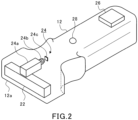
- the ultrasonic transducer 22 is built in the distal end portion 12a of the probe 12.
- the ultrasonic transducer 22 includes one or a plurality of oscillators.
- the oscillator is formed of, for example, a piezoelectric element. When voltage is applied to the oscillator, the oscillator causes oscillation.
- the ultrasonic transducer 22 generates an ultrasonic wave through the oscillation by the oscillator, and emits the generated ultrasonic wave from the distal end portion 12a of the probe 12.
- the ultrasonic transducer 22 can radiate the ultrasonic wave onto the living body 2 through the sheet material 10.
- the ultrasonic wave radiated to the inside of the living body 2 propagates inside the living body 2, and is, for example, reflected by an organ or the like located inside the living body 2. A part of the reflected ultrasonic wave propagates inside the living body 2 and returns to the ultrasonic transducer 22.
- the ultrasonic wave that is reflected and then reaches the ultrasonic transducer 22 may be referred to as an ultrasonic wave echo.
- the ultrasonic transducer 22 can receive the ultrasonic wave echo reflected inside the living body 2.
- the oscillator of the ultrasonic transducer 22 causes oscillation when receiving the ultrasonic wave echo, and converts the oscillation into voltage. The converted voltage is transmitted to the flaw detection device 14.
- the flaw detection device 14 illustrated in FIG. 1 is electrically connected to the ultrasonic transducer 22.
- the flaw detection device 14 performs control related to radiation of the ultrasonic wave by the ultrasonic transducer 22. For example, the flaw detection device 14 scans an irradiation direction of the ultrasonic wave in a direction in which a side surface in the distal end portion 12a of the probe 12 protrudes. Further, the flaw detection device 14 can acquire the voltage indicating the ultrasonic wave echo received by the ultrasonic transducer 22.
- the flaw detection device 14 performs predetermined signal processing such as A/D conversion on the acquired voltage, and transmits the signal having been subjected to the signal processing to the image generating device 16. Although having been subjected to the predetermined signal processing, the signal transmitted by the image generating device 16 is data indicating the ultrasonic wave echo.
- the imaging device 24 includes a light guiding portion 24a, a lens 24b, and a light receiving element 24c.
- the light guiding portion 24a is provided at the distal end portion 12a of the probe 12 and arranged adjacent to the ultrasonic transducer 22. A distal end portion of the light guiding portion 24a is directed forward from the distal end portion 12a of the probe 12.
- the lens 24b is arranged at a rear end portion of the light guiding portion 24a.
- the light receiving element 24c is arranged on a side opposite to the light guiding portion 24a in the lens 24b.
- the light guiding portion 24a is formed into a box shape from a material that guides light.
- the imaging device 24 is installed so as to be capable of imaging a forward side from the distal end portion 12a of the probe 12 at the distal end portion 12a of the probe 12.
- the imaging device 24 is installed so as to be capable of generally imaging the irradiation direction of the ultrasonic transducer 22 in the vicinity of the ultrasonic transducer 22.
- the imaging device 24 can image the two-dimensional code 20 on the surface 10a of the sheet material 10 within a field of view of the imaging device 24.
- Image data including the two-dimensional code 20 imaged by the imaging device 24 is transmitted to the image generating device 16.
- the image generating device 16 can specify the position of the probe 12 on the surface 10a of the sheet material 10 based on the two-dimensional code 20 imaged by the imaging device 24.
- the inclination angle sensor 26 is installed at a rear end portion 12b of the probe 12.
- the inclination angle sensor 26 is not limited to the mode of being installed at the rear end portion 12b, and may be installed at any position on the probe 12.
- the inclination angle sensor 26 is formed of, for example, micro electro mechanical systems (MEMS).
- MEMS micro electro mechanical systems
- the inclination angle sensor 26 can detect an inclination angle of the probe 12 with respect to a vertical direction.
- a direction along a direction in which the side surface at the distal end portion 12a of the probe 12 protrudes is defined as an A direction
- a direction along a direction in which the side surface at the distal end portion 12a of the probe 12 does not protrude is defined as a B direction.
- an angle about an axis of the A direction is defined as an inclination angle ⁇ a
- an angle about an axis of the B direction is defined as an inclination angle ⁇ b.
- an angle about an axis of the X direction of the sheet material 10 is defined as an inclination angle ⁇ x
- an angle about an axis of the Y direction of the sheet material 10 is defined as an inclination angle ⁇ y.
- the inclination angle sensor 26 can detect each of an absolute inclination angle ⁇ a and an absolute inclination angle ⁇ b of the probe 12 with respect to the vertical direction.
- the inclination angle ⁇ a and the inclination angle ⁇ b are inclination angles of the probe 12 in a coordinate system.
- the detection result given by the inclination angle sensor 26 is transmitted to the image generating device 16.
- the image generating device 16 can specify the inclination angle ⁇ x and the inclination angle ⁇ y, which are inclination angles of the probe 12 with respect to the vertical direction and are inclination angles of the sheet material 10 in a coordinate system based on the inclination angle ⁇ a and the inclination angle ⁇ b detected by the inclination angle sensor 26 and the angle ⁇ z of the probe 12.
- the operation switch 28 is provided on a side surface side on which the side surface does not protrude in the distal end portion 12a.
- the operation switch 28 is provided closer to the distal end portion 12a than the center in the axial direction of the probe 12 extending from the rear end portion 12b to the distal end portion 12a.
- the operation switch 28 is not limited to the mode of being provided at the exemplified position, and may be provided at any position on the probe 12.
- the operation switch 28 receives an input operation by a user, and information indicating the input operation is transmitted to the image generating device 16. For example, when the operation switch 28 is pressed, the image generating device 16 may store, for example, an image indicating a result of ultrasound diagnostic in a storage device 34 described later.
- the communication unit 30 can communicate with the flaw detection device 14 in a wired or wireless manner. Further, the communication unit 30 can communicate also with the imaging device 24 and the inclination angle sensor 26 in a wired or wireless manner. The communication unit 30 may communicate directly with the imaging device 24 and the inclination angle sensor 26 without interposing the flaw detection device 14, or may communicate indirectly with the imaging device 24 and the inclination angle sensor 26 via the flaw detection device 14.
- the user interface 32 includes a display unit 32a that displays various images or pieces of information.
- Examples of the display unit 32a include various display devices such as a liquid crystal display and an organic EL display.
- the user interface 32 may include, besides the display unit 32a, an output device that presents various pieces of information to a user, such as a speaker. Further, the user interface 32 includes an input device such as a keyboard or a mouse that receives an input operation of a user.
- the storage device 34 is formed of a non-volatile storage element, and functions as a storage unit.
- the data indicating the ultrasonic wave echo detected by the ultrasonic transducer 22 may be stored.
- the diagnostic image generated by the image generating device 16 may be stored. In this case, the diagnostic image and the position of the probe 12 and the inclination angle of the probe 12 corresponding to the diagnostic image may be stored in the storage device 34 in association with each other.
- the control device 36 includes one or a plurality of processors 40 and one or a plurality of memories 42 connected to the processors 40.
- the memory 42 includes a ROM in which a program or the like is stored and a RAM as a work area.
- the processor 40 controls the entire image generating device 16 in cooperation with a program included in the memory 42.
- the control device 36 of the image generating device 16 executes the program to also function as a probe specifying unit 50 and an image generating unit 52.
- the probe specifying unit 50 specifies the position of the probe 12 on the surface 10a of the sheet material 10 based on the two-dimensional code 20 imaged by the imaging device 24.
- the probe 12 is placed on the surface 10a of the sheet material 10 in a state in which the sheet material 10 is attached to the surface of the living body 2.
- the position of the probe 12 on the surface 10a of the sheet material 10 is specified, the position of the probe 12 on the surface of the living body 2 is specified as a consequence.
- the image generating unit 52 generates a diagnostic image indicating the result of ultrasound diagnostic of the living body 2 based on the ultrasonic wave echo acquired through the ultrasonic transducer 22 and the flaw detection device 14.
- the image generating unit 52 may generate, in addition to the diagnostic image, various images relating to ultrasound diagnostic as described later. Further, the image generating unit 52 also functions as a display control unit that controls the display unit 32a.
- the image generating unit 52 causes the display unit 32a to display various generated images such as a diagnostic image, a captured image captured by the imaging device, or other various pieces of information.
- FIG. 3 is an explanatory view for illustrating a method of specifying the position of the probe 12 according to the first embodiment.
- some of the plurality of two-dimensional codes 20 on the sheet material 10 are illustrated.
- a frame 60 of FIG. 3 is an example of a captured image captured by the imaging device 24.
- identification points 62 are set at three corners of the square two-dimensional surface.
- the probe specifying unit 50 acquires the captured image from the imaging device 24 through the communication unit 30.
- the probe specifying unit 50 searches for the identification point 62 closest to a center T of the captured image based on the acquired captured image.
- the probe specifying unit 50 also specifies the other two identification points 62 in relation to the found identification point 62, and specifies the two-dimensional code 20 closest to the center T.
- a two-dimensional code 20a is the two-dimensional code 20 closest to the center T.
- the probe specifying unit 50 derives the position of the center T of the captured image on the surface 10a of the sheet material 10 based on the position of the specified two-dimensional code 20a, the derived angle ⁇ z, and the position of the two-dimensional code 20a1 that is not rotated within the captured image.
- the distance between the imaging device 24 and the ultrasonic transducer 22, that is, the offset amount of the center T of the captured image with respect to the ultrasonic transducer 22 is stored in advance .
- the probe specifying unit 50 specifies the position of the probe 12 on the surface 10a of the sheet material 10 based on the derived position of the center T of the captured image and the offset amount stored in the storage device 34.
- the specified position of the probe 12 corresponds to the position of the probe 12 on the surface of the living body 2.
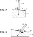
- ultrasound diagnostic of the living body 2 When ultrasound diagnostic of the living body 2 is to be performed, as illustrated in FIG. 4A , basically, the user performs ultrasound diagnostic while erecting the probe 12 perpendicularly to the surface 10a of the sheet material 10 so as to radiate the ultrasonic wave to the inside of the living body 2 approximately perpendicularly from the surface of the living body 2.
- the ultrasonic wave when the ultrasonic wave is radiated perpendicularly as in FIG. 4A , for example, the ultrasonic wave may be blocked by bones or other organs, with the result that the ultrasonic wave is difficult to reach a target organ.
- diagnosis may be desired to be performed by radiating the ultrasonic wave onto the target organ from a plurality of directions.
- a diagnosis person may perform ultrasound diagnostic of the target organ while pushing the probe 12 in a direction toward the inside of the living body 2 and inclining the probe 12 with respect to the surface of the living body 2.
- the abdomen or the like of the living body 2 is a soft body with its surface being flexibly deformable.
- the probe specifying unit 50 associates the specified position of the probe 12 and the specified inclination angle of the probe 12 with each other. Further, it is preferred that the probe specifying unit 50 associate the specified position of the probe 12, the specified inclination angle of the probe 12, and an ultrasonic wave echo given when the position of the probe 12 and the inclination angle of the probe 12 are specified.
- the probe specifying unit 50 may store the associated data in the storage device 34.
- FIG. 6 is a view for illustrating an example of a display screen of the display unit 32a according to the first embodiment.
- the image generating unit 52 generates a waveform image 70 indicating a time transition of an amplitude of an ultrasonic wave echo based on the data indicating the ultrasonic wave echo. As illustrated in FIG. 6 , the image generating unit 52 displays the waveform image 70 in a lower left region among the four divided regions of the display screen.
- a time scale 72a indicating a time is associated with one side extending in the left-and-right direction at the lower portion of the waveform image 70.
- An amplitude scale 72b indicating an amplitude of the ultrasonic wave echo is associated with other one side extending in the up-and-down direction at a left portion of the waveform image 70.
- a plane length scale 76b indicating a length in a plane direction substantially parallel to the surface of the living body 2 is associated with other one side extending in the left-and-right direction at a lower portion of each of the first diagnostic image 74a and the second diagnostic image 74b.
- a user sequentially performs ultrasound diagnostic of a plurality of organs inside the living body 2 one by one. For example, at the time of switching an organ to be diagnosed to a next organ, a user moves the probe 12 on the sheet material 10 along the surface 10a of the sheet material 10 from a position corresponding to the organ before switching to a position corresponding to the organ after switching. Such movement of the probe 12 on the sheet material 10 is one mode of scanning by the probe 12.
- the image generating unit 52 is not limited to the mode of displaying the generated various images in the arrangement exemplified in FIG. 6 , and the image generating unit 52 may display the generated various images in any arrangement.
- the image generating unit 52 generates a position image 82 indicating a current position of the probe 12 based on the position of the probe 12 specified by the probe specifying unit 50. As illustrated in FIG. 6 , the image generating unit 52 superimposes the position image 82 on the diagnostic image 74 and displays the superimposed position image 82 on the display unit 32a.
- the position image 82 is a cursor including a horizontal line 82a and a vertical line 82b.
- the horizontal line 82a indicates a position of the sheet material 10 in the X direction in the position of the probe 12 on the sheet material 10.
- the vertical line 82b indicates a position of the sheet material 10 in the Y direction in the position of the probe 12 on the sheet material 10.
- a portion of the surface of the living body 2, with which the probe 12 is in contact, with the sheet material 10 interposed therebetween is defined as a reference portion.
- the image generating unit 52 derives a relationship between an irradiation distance of the ultrasonic wave from the reference portion in the irradiation direction of the ultrasonic wave and a depth of the living body 2 in a direction toward the inside from the reference portion based on the irradiation distance and the inclination angle of the probe 12.
- the image generating unit 52 sets the value of the depth scale 76a in the diagnostic image 74 based on the relationship between the derived irradiation distance and the depth.
- the image generating unit 52 performs image processing such that the first diagnostic image 74a is line-symmetric in the left-and-right direction with the center of the first diagnostic image 74a in the left-and-right direction as a symmetric axis, and then displays the first diagnostic image 74a after the image processing on the display unit 32a.
- the image generating unit 52 may set the value of the plane length scale 76b of the diagnostic image 74 based on the position of the probe 12. Further, the image generating unit 52 may generate the diagnostic image 74 based on the ultrasonic wave echo, the position of the probe 12, and the inclination angle of the probe 12.
- FIG. 7 is an explanatory flowchart for illustrating a flow of operations of the control device 36 according to the first embodiment.
- the control device 36 executes a series of processing illustrated in FIG. 7 each time a predetermined interrupt timing that arrives in a predetermined cycle comes.
- the probe specifying unit 50 of the control device 36 executes probe specifying processing (S11) of specifying the position of the probe 12 and the inclination angle of the probe 12.
- the probe specifying processing (S11) is to be described in detail later.
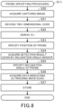
- FIG. 8 is an explanatory flowchart for illustrating a flow of the probe specifying processing (S11) according to the first embodiment.
- the probe specifying unit 50 acquires the captured image which is captured by the imaging device 24 from the imaging device 24 through the communication unit 30 (S20).
- the probe specifying unit 50 decodes the two-dimensional code 20 in the acquired captured image and acquires coordinate data in the two-dimensional code 20 (S21) .
- the probe specifying unit 50 derives the angle ⁇ z of the probe 12 about the axis of the Z direction with respect to the sheet material 10 based on the orientation of the captured image of the decoded two-dimensional code 20 (S22).
- the probe specifying unit 50 specifies the position of the probe 12 with respect to the sheet material 10 based on the coordinate data of the decoded two-dimensional code 20, the angle ⁇ z, and the offset amount of the imaging device 24 stored in the storage device 34 (S23).
- the probe specifying unit 50 acquires the detection result given by the inclination angle sensor 26 through the communication unit 30 (S24). For example, the probe specifying unit 50 acquires the inclination angle ⁇ a and the inclination angle ⁇ b which are the detection results detected by the inclination angle sensor 26.
- the probe specifying unit 50 acquires the data indicating the ultrasonic wave echo through the ultrasonic transducer 22 and the flaw detection device 14 (S26).
- the probe specifying unit 50 associates the data indicating the ultrasonic wave echo acquired in Step S26, the angle ⁇ z specified in Step S22, the position of the probe 12 specified in Step S23, and the inclination angle of the probe 12 specified in Step S25 with one another, stores them in the storage device 34 (S27), and ends the probe specifying processing.
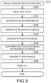
- FIG. 9 is an explanatory flowchart for illustrating a flow of the image generating processing (S12) according to the first embodiment.
- the image generating unit 52 reads out data necessary for generating various images from the storage device 34 (S30).
- the various pieces of data acquired and derived in the probe specifying processing may be used in processing subsequent to Step S31 of the image generating processing without performing the storing processing of Step S27 and the reading processing of Step S30.
- the image generating unit 52 generates the waveform image 70 indicating the time transition of the amplitude of the ultrasonic wave echo based on the data indicating the ultrasonic wave echo (S31).
- the image generating unit 52 generates the position image 82 representing the position of the probe 12 on the image based on the specified position of the probe 12 (S33) .
- the image generating unit 52 superimposes the position image 82 generated in Step S33 on the diagnostic image 74 generated in Step S32 (S34).
- the image generating unit 52 generates the area image 78 corresponding to a range in which the sheet material 10 is attached in the living body 2 (S35). In this case, when scanning by the probe 12 is not performed in the entire range of the area image 78, the image generating unit 52 generates an area image in which a display mode of the entire range of the area image 78 is set to an initial display mode. Further, when there is a portion in which a predetermined condition indicating that scanning by the probe 12 has been performed is satisfied in the area image 78, the image generating unit 52 generates an area image 78 in which the display mode of the portion is changed from the initial display mode of the portion before scanning by the probe 12 is performed.
- the order of the generation of the waveform image 70, the generation of the diagnostic image 74, the generation of the position image 82, and the generation of the area image 78 shows an example, and is not limited to the exemplified order and may be any order. Further, the processing of superimposing the position image 82 on the diagnostic image 74 may be performed in any order after both the diagnostic image 74 and the position image 82 are generated.
- the image generating unit 52 may perform the processing of superimposing the position image 82 on the waveform image 70, or may perform the processing of superimposing the position image 82 on the area image 78.
- the image generating unit 52 arranges the generated images at respective prescribed positions on the display screen, displays the generated images on the display unit 32a of the user interface 32 (S36), and ends the image generating processing.
- the image generating unit 52 arranges the diagnostic image 74 on which the position image 82 is superimposed in the lower right region and the upper right region among the four divided regions of the display screen, arranges the waveform image 70 in the lower left region, and arranges the area image 78 in the upper left region, thereby displaying the respective images.
- the imaging device 24 and the inclination angle sensor 26 are provided to the probe 12.
- the probe specifying unit 50 specifies the position of the probe 12 on the surface of the living body 2 based on the two-dimensional code 20 on the surface 10a of the sheet material 10 which is imaged by the imaging device 24, and specifies the inclination angle of the probe 12 with respect to the vertical direction based on the detection result given by the inclination angle sensor 26.
- the relationship between the position of the probe 12 with respect to the surface of the living body 2 and the posture of the probe 12 can be appropriately grasped.
- the ultrasound diagnostic device 1 of the first embodiment with reference to the specified inclination angle of the probe 12, it is possible to appropriately distinguish whether the specified position of the probe 12 has been obtained as a result of performing ultrasound diagnostic without inclination of the probe 12 or has been obtained as a result of performing ultrasound diagnostic while pushing the probe 12 into the living body and inclining the probe 12.
- the inclination angle of the probe 12 with respect to the vertical direction is specified in the coordinate system of the sheet material 10.
- the direction of the ultrasonic wave emitted from the probe 12 can be specified in the coordinate system of the sheet material 10 based on the specified inclination angle of the probe 12.
- the irradiation direction of the ultrasonic wave radiated to the inside of the living body 2 can be accurately grasped.
- ultrasound diagnostic of the living body 2 For example, a plurality of organs in the living body 2 may be diagnosed in a predetermined order one by one. In such a case, it is desired to accurately diagnose each organ. In view of this, in a second embodiment, it is determined whether or not the position and the inclination angle of the probe 12 are appropriate for each organ to be diagnosed, thereby assisting ultrasound diagnostic.
- FIG. 10 is a schematic view for illustrating a configuration of an ultrasound diagnostic device 100 according to the second embodiment.
- diagnostic procedure information 134a and diagnostic reference information 134b are stored in advance.
- the diagnostic procedure information 134a is information in which an execution procedure of ultrasound diagnostic in the living body 2 is set.
- the order of organs to be subjected to ultrasound diagnostic or the priority order of organs to be subjected to ultrasound diagnostic are included.
- the diagnostic reference information 134b is information in which a specific organ in the living body 2, an allowable range of the position of the probe 12 for diagnosing the specific organ, and an allowable range of the inclination angle of the probe 12 for diagnosing the specific organ are associated with one other.
- the diagnostic reference information 134b is set for each organ for a plurality of organs that can be subjected to ultrasound diagnostic.
- the processor 40 of the control device 36 of the image generating device 16 executes the program, thereby also functioning as a diagnostic procedure management unit 154.
- the diagnostic procedure management unit 154 specifies an organ to be subjected to ultrasound diagnostic among the plurality of organs that can be subjected to ultrasound diagnostic based on the diagnostic procedure information 134a, and prompts the user to perform an operation of the probe 12 for diagnosing the specified organ.
- the diagnostic procedure management unit 154 sequentially switches an organ to be subjected to ultrasound diagnostic based on the diagnostic procedure information 134a, and manages the progress of the ultrasound diagnostic.
- the probe specifying unit 50 determines whether or not the current position of the probe 12 is within the allowable range of the position of the probe 12 indicated by the diagnostic reference information 134b at the time of diagnosing a specific organ.
- the probe specifying unit 50 determines whether or not the current inclination angle of the probe 12 is within the allowable range of the inclination angle of the probe 12 indicated by the diagnostic reference information 134b at the time of diagnosing a specific organ.
- the probe specifying unit 50 outputs a predetermined alarm in at least one of a case in which the current position of the probe 12 is out of the allowable range of the position of the probe 12 indicated by the diagnostic reference information 134b and a case in which the current inclination angle of the probe 12 is out of the allowable range of the inclination angle of the probe 12 indicated by the diagnostic reference information 134b.
- the probe specifying unit 50 displays on the display unit 32a that at least one of the position of the probe 12 and the inclination angle of the probe 12 is not appropriate.
- the predetermined alarm is not limited to the display on the display unit 32a, and may be performed, for example, in any mode such as an alarm sound, which can be recognized by the user.
- FIG. 11 is an explanatory flowchart for illustrating a flow of operations of the control device 36 according to the second embodiment.
- the control device 36 executes a series of processing illustrated in FIG. 11 each time a predetermined interrupt timing that arrives in a predetermined cycle comes.
- the diagnostic procedure management unit 154 of the control device 36 first determines an organ to be diagnosed based on the diagnostic procedure information 134a (S40). In this case, the diagnostic procedure management unit 154 may present the determined organ in a mode that can be recognized by the user, and prompt the operation of the probe 12.
- the probe specifying unit 50 performs the probe specifying processing (S11) for the determined current organ, and performs the image generating processing (S12).
- the probe specifying processing in this case is similar to the probe specifying processing of the first embodiment, and the image generating processing in this case is similar to the image generating processing of the first embodiment.
- the probe specifying unit 50 determines whether or not the current position of the probe 12 specified in the probe specifying processing is within the allowable range of the position of the probe 12 indicated by the diagnostic reference information 134b (S43).
- the probe specifying unit 50 determines whether or not the current inclination angle of the probe 12 specified in the probe specifying processing is within the allowable range of the inclination angle of the probe 12 indicated by the diagnostic reference information 134b (S44).
- the probe specifying unit 50 When the current position of the probe 12 is out of the allowable range of the position of the probe 12 indicated by the diagnostic reference information 134b (NO in S43), the probe specifying unit 50 outputs the predetermined alarm (S45). After outputting the predetermined alarm, the probe specifying unit 50 returns to Step S43, and repeats processing subsequent to Step S43.
- the probe specifying unit 50 When the current inclination angle of the probe 12 is out of the allowable range of the inclination angle of the probe 12 indicated by the diagnostic reference information 134b (NO in S44), the probe specifying unit 50 outputs the predetermined alarm (S45). After outputting the predetermined alarm, the probe specifying unit 50 returns to the processing of Step S43, and repeats processing subsequent to Step S43.
- the probe specifying unit 50 resets the alarm (S46).
- the series of processing in FIG. 11 may be ended at a time point in which the predetermined time has elapsed.
- the diagnostic procedure management unit 154 determines whether or not diagnosis of a current organ has been completed (S47). For example, when the diagnosis of the current organ is completed by operating the probe 12, the user may input that the diagnosis of the current organ has been completed via the user interface 32. Further, the diagnostic procedure management unit 154 may determine that the diagnosis of the current organ has been completed when an input operation of the operation switch 28 of the probe 12 is performed.
- the diagnostic procedure management unit 154 When determining that the diagnosis of the current organ has not been completed (NO in S47), the diagnostic procedure management unit 154 returns to processing of Step S43, and repeats processing subsequent to Step S43.
- the diagnostic procedure management unit 154 determines whether or not diagnosis of all the organs that can be subjected to ultrasound diagnostic set in the diagnostic procedure information 134a has been completed (S48).
- the diagnostic procedure management unit 154 When determining that diagnosis of all the organs has not been completed (NO in S48), the diagnostic procedure management unit 154 returns to the processing of Step S40, determines an organ to be diagnosed next based on the diagnostic procedure information 134a (S40), and repeats subsequent processing.
- the diagnostic procedure management unit 154 ends a series of processing in FIG. 11 .
- the probe specifying processing is performed, thereby being capable of appropriately grasping the relationship between the position of the probe 12 with respect to the surface of the living body 2 and the posture of the probe 12.
- an alarm is output when the position of the probe 12 and the inclination angle of the probe 12 at the time of diagnosing a specific organ do not have an allowable appropriate value for diagnosing the specific organ.
- the execution of ultrasound diagnostic is progressed based on the diagnostic procedure information 134a stored in advance.
- the ultrasound diagnostic device 100 of the second embodiment it is possible to prevent a selection error of an organ to be diagnosed, an error in the order of diagnosis, and the like.
- the inclination angle of the probe 12 with respect to the vertical direction is specified based on the detection result given by the inclination angle sensor 26 provided to the probe 12.
- the posture of the probe 12 is substantially horizontal, that is, when the inclination angle of the probe 12 with respect to the vertical direction is approximately 90°, the inclination angle sensor 26 formed of MEMS may not be able to appropriately detect the inclination angle of the probe 12.
- an azimuth sensor that detects the posture of the probe 12 may be provided to the probe 12.
- the azimuth sensor can detect the inclination angle of the probe 12 with respect to the vertical direction based on magnetism (for example, geomagnetism). Even when the posture of the probe 12 is substantially horizontal, the azimuth sensor can appropriately detect the inclination angle of the probe 12 with respect to the vertical direction.
- the probe specifying unit 50 may specify the inclination angle of the probe 12 with respect to the vertical direction based on the detection result given by the azimuth sensor.
- the probe specifying unit 50 derives the inclination angle ⁇ x and the inclination angle ⁇ y in the coordinate system of the sheet material 10 based on the inclination angle ⁇ a and the inclination angle ⁇ b detected by an azimuth angle sensor and the angle ⁇ z. According to this mode, even when the posture of the probe 12 is substantially horizontal, the inclination angle of the probe 12 can be appropriately detected, and the inclination angle of the probe 12 can be more accurately specified.
- the azimuth angle sensor may be provided to the probe 12 as the inclination angle sensor 26.
- the azimuth angle sensor is configured to detect the inclination angle of the probe 12 based on magnetism.
- a device that generates and utilizes a magnetic field such as a magnetic resonance image diagnosis device may be installed, and there is a fear in that the detection accuracy by the azimuth sensor may be lowered.
- the inclination angle sensor 26 formed of MEMS can detect the inclination angle of the probe 12 without being affected by magnetism.
- the mode of using the inclination angle sensor 26 formed of MEMS is more preferable than the mode of using the azimuth sensor as the inclination angle sensor 26.
- the present disclosure can contribute to, for example, Goal 12 of Sustainable Development Goals (SDGs) "Ensure sustainable consumption and production patterns”.
- SDGs Sustainable Development Goals
Landscapes
- Health & Medical Sciences (AREA)
- Life Sciences & Earth Sciences (AREA)
- Engineering & Computer Science (AREA)
- Physics & Mathematics (AREA)
- Radar, Positioning & Navigation (AREA)
- Remote Sensing (AREA)
- Pathology (AREA)
- Molecular Biology (AREA)
- Biophysics (AREA)
- Nuclear Medicine, Radiotherapy & Molecular Imaging (AREA)
- Veterinary Medicine (AREA)
- Radiology & Medical Imaging (AREA)
- Biomedical Technology (AREA)
- Heart & Thoracic Surgery (AREA)
- Medical Informatics (AREA)
- Public Health (AREA)
- Surgery (AREA)
- Animal Behavior & Ethology (AREA)
- General Health & Medical Sciences (AREA)
- General Physics & Mathematics (AREA)
- Computer Networks & Wireless Communication (AREA)
- Acoustics & Sound (AREA)
- Ultra Sonic Daignosis Equipment (AREA)
Abstract
Description
- The present disclosure relates to an ultrasound diagnostic device. This application claims the benefit of priority of
Japanese Patent Application No. 2022-19567 filed on February 10, 2022 - For example, Patent Literature 1 discloses a technology in which a sheet material having a two-dimensional code drawn on a surface thereof is attached to a surface of a pipe, and ultrasonic wave flaw detection for the pipe is performed from above the sheet material. In such a technology, a reader that reads the two-dimensional code is mounted to the ultrasonic transducer, and position data on the pipe is acquired based on the two-dimensional code read by the reader.
- Patent Literature 1:
JP 2017-203786 A - In Patent Literature 1, in order to appropriately perform the ultrasonic wave flaw detection for the pipe, an ultrasonic wave is radiated onto the surface of the pipe in a direction perpendicular to the surface of the pipe. That is, the ultrasonic transducer that emits the ultrasonic wave is arranged perpendicularly to the surface of the pipe. Further, in Patent Literature 1, an object to be subjected to the ultrasonic wave flaw detection is a pipe. The pipe is a rigid body, and hence does not deform at the time of the ultrasonic wave flaw detection. Thus, in Patent Literature 1, the ultrasonic wave flaw detection for the pipe is performed while maintaining a state in which the ultrasonic transducer is arranged perpendicularly to the surface of the pipe.
- Incidentally, for example, ultrasound diagnostic may be performed on various organs inside an abdomen of a living body using the ultrasound diagnostic device. In this case, when the ultrasonic wave is radiated from the surface of the living body to the inside of the living body in a direction perpendicular to the surface of the living body, for example, the ultrasonic wave may be blocked by bones or other organs, with the result that the ultrasonic wave is difficult to reach a target organ. Further, diagnosis may be desired to be performed by radiating the ultrasonic wave onto the target organ from a plurality of directions. In these cases, a diagnosis person may perform ultrasound diagnostic of the target organ while pushing the probe in a direction toward the inside of the living body and inclining the probe, which is provided with the ultrasonic transducer, with respect to the direction perpendicular to the surface of the living body to avoid the bones or the like. The abdomen or the like of the living body is a soft body with its surface being flexibly deformable. Thus, the probe can be pushed in the direction toward the inside of the living body and inclined.
- In this case, when the probe is pushed and inclined from a state in which the probe is not pushed, the position of the probe with respect to the surface of the living body may not substantially change. For example, it is assumed that the technology of Patent Literature 1 is applied to ultrasound diagnostic of the living body so that position data of the probe with respect to the surface of the living body can be acquired. It is difficult to appropriately distinguish whether the position data of the probe acquired in this manner has been obtained as a result of performing ultrasound diagnostic without inclination of the probe or has been obtained as a result of performing ultrasound diagnostic while pushing the probe into the living body and inclining the probe. In Patent Literature 1, the ultrasonic wave flaw detection for the pipe which is a rigid body is performed. Thus, when the ultrasonic transducer is inclined in the direction perpendicular to the surface of the pipe, accuracy of the ultrasonic wave flaw detection is lowered, with the result that the idea of intentionally inclining the ultrasonic transducer with respect to the direction perpendicular to the surface of the pipe is not reached.
- The present disclosure has an object to provide an ultrasound diagnostic device capable of appropriately grasping a relationship between a position of a probe with respect to a surface of a living body and a posture of the probe.
- In order to solve the problem described above, an ultrasound diagnostic device according to an aspect of the present disclosure includes: a sheet material that is capable of being attached to a surface of a living body and has a two-dimensional code drawn on a surface thereof, the two-dimensional code representing a position within the surface of the sheet material; an ultrasonic transducer configured to radiate an ultrasonic wave onto the living body through the sheet material, and receive an ultrasonic wave echo reflected inside the living body; a probe that is movable on the surface of the living body having the sheet material attached thereto and is provided with the ultrasonic transducer; an imaging device that is provided to the probe and is capable of imaging the two-dimensional code; an inclination angle sensor provided to the probe; a probe specifying unit configured to specify a position of the probe on the surface of the living body based on the two-dimensional code imaged by the imaging device, and specify an inclination angle of the probe with respect to a vertical direction based on a detection result given by the inclination angle sensor; and an image generating unit configured to generate a diagnostic image indicating a result of ultrasound diagnostic of the living body based on the ultrasonic wave echo.
- The image generating unit may be configured to: associate a depth scale indicating a depth from the surface of the living body with one side of the diagnostic image corresponding to an irradiation direction of the ultrasonic wave; and set at least one of a value of the depth scale and a scale of the diagnostic image based on an inclination angle of the probe.
- The image generating unit may be configured to generate a position image indicating a current position of the probe based on the position of the probe specified by the probe specifying unit, and superimpose the position image on the diagnostic image.
- The probe specifying unit may be configured to specify an orientation of the probe indicating an angle about an axis of a direction normal to the surface of the sheet material in the probe based on the two-dimensional code imaged by the imaging device, and the image generating unit may be configured to generate, when the orientation of the probe exceeds a predetermined range, the diagnostic image inverted in a left-and-right direction in a plane direction along the surface of the sheet material in the diagnostic image.
- The image generating unit may be configured to: generate an area image corresponding to a range in which the sheet material is attached in the living body; and change a display mode of a portion satisfying a predetermined condition indicating that scanning by the probe has been performed in the area image, from an initial display mode of the portion before the scanning by the probe is performed.
- The ultrasound diagnostic device may further include a storage unit configured to store in advance diagnostic reference information in which an allowable range of the position of the probe for diagnosing a specific organ in the living body and an allowable range of the inclination angle of the probe for diagnosing the specific organ are associated with each other. The probe specifying unit may be configured to output a predetermined alarm in at least one of a case in which a current position of the probe is out of the allowable range of the position of the probe indicated by the diagnostic reference information and a case in which a current inclination angle of the probe is out of the allowable range of the inclination angle of the probe indicated by the diagnostic reference information, at the time of diagnosing the specific organ.
- The ultrasound diagnostic device may further comprise an azimuth sensor configured to detect a posture of the probe. The probe specifying unit may be configured to specify, when an inclination angle of the inclination angle sensor exceeds an upper limit value of a detection range of the inclination angle sensor, the inclination angle of the probe with respect to the vertical direction based on a detection result given by the azimuth sensor.
- According to the present disclosure, it is possible to appropriately grasp a relationship between a position of a probe with respect to a surface of a living body and a posture of the probe.
-
-
FIG. 1 is a schematic view for illustrating a configuration of an ultrasound diagnostic device according to a first embodiment. -
FIG. 2 is a perspective view for illustrating a configuration of a probe. -
FIG. 3 is an explanatory view for illustrating a method of specifying a position of the probe according to the first embodiment. -
FIG. 4A is a view for illustrating an example of performing ultrasound diagnostic substantially without inclination of the probe according to the first embodiment. -
FIG. 4B is a view for illustrating an example of performing ultrasound diagnostic with inclination of the probe according to the first embodiment. -
FIG. 5 is an explanatory view for illustrating a method of specifying an inclination angle of the probe according to the first embodiment. -
FIG. 6 is a view for illustrating an example of a display screen of a display unit according to the first embodiment. -
FIG. 7 is an explanatory flowchart for illustrating a flow of operations of a control device according to the first embodiment. -
FIG. 8 is an explanatory flowchart for illustrating a flow of probe specifying processing according to the first embodiment. -
FIG. 9 is an explanatory flowchart for illustrating a flow of image generating processing according to the first embodiment. -
FIG. 10 is a schematic view for illustrating a configuration of an ultrasound diagnostic device according to a second embodiment. -
FIG. 11 is an explanatory flowchart for illustrating a flow of operations of the control device according to the second embodiment. - Now, with reference to the attached drawings, embodiments of the present disclosure are described in detail. The dimensions, materials, and other specific numerical values represented in the embodiments are merely examples used for facilitating the understanding of the disclosure, and do not limit the present disclosure otherwise particularly noted. Elements having substantially the same functions and configurations herein and in the drawings are denoted by the same reference symbols to omit redundant description thereof. Further, illustration of elements with no direct relationship to the present disclosure is omitted.
-
FIG. 1 is a schematic view for illustrating a configuration of an ultrasound diagnostic device 1 according to a first embodiment. The ultrasound diagnostic device 1 of the first embodiment diagnoses, for example, aliving body 2 such as a human body as a diagnosis object, and performs ultrasound diagnostic on the diagnosis object. The diagnosis object is not limited to theliving body 2, and may be any object. The ultrasound diagnostic device 1 includes asheet material 10, aprobe 12, aflaw detection device 14, and animage generating device 16. - The
sheet material 10 is made of a material that transmits an ultrasonic wave, and is formed into a flexible sheet shape. A shape of asurface 10a of thesheet material 10 is a quadrangular shape, but is not limited to the quadrangular shape, and may be any shape. Thesheet material 10 is capable of being attached to the surface of the livingbody 2. For example, a contact medium for transmitting an ultrasonic wave is applied to a surface of an abdomen of the livingbody 2, and thesheet material 10 is attached onto the contact medium. - On the
surface 10a of thesheet material 10, two-dimensional codes 20 each representing a position within thesurface 10a of thesheet material 10 are drawn. The two-dimensional code 20 is, for example, a QR code (registered trademark). In the two-dimensional code 20, encrypted data is described on a square two-dimensional surface. - Here, as illustrated in
FIG. 1 , a direction along one side of thesheet material 10 is defined as an X direction, and a direction along other one side orthogonal to the X direction is defined as a Y direction. Further, a direction normal to thesurface 10a of thesheet material 10 is defined as a Z direction. A plurality of two-dimensional codes 20 are arranged at a predetermined interval in each of the X direction and the Y direction of thesheet material 10. The predetermined interval can be freely set at, for example, 10 mm. InFIG. 1 , the two-dimensional codes 20 are illustrated at a part of thesurface 10a, but the two-dimensional codes 20 are drawn over theentire surface 10a of thesheet material 10. - In the two-
dimensional code 20, coordinate data indicating the position within thesurface 10a of thesheet material 10 is encrypted. For example, a two-dimensional code 20 arranged at a predetermined one corner (for example, a right lower corner in thesheet material 10 ofFIG. 1 ) of thesheet material 10 is set as a two-dimensional code 20 at a reference position. Coordinate data of "m, n" is encrypted on a two-dimensional code 20 located at an m-th position in the X direction and at an n-th position in the Y direction from the two-dimensional code 20 at the reference position. As will be described later, the position within thesurface 10a of thesheet material 10 can be specified based on the coordinate data and the predetermined interval of the two-dimensional codes 20. - The
probe 12 is formed into, for example, a rod shape that can be grasped by a user (for example, a diagnosis person who performs ultrasound diagnostic) of the ultrasound diagnostic device 1. Adistal end portion 12a of theprobe 12 expands in a T shape. When performing ultrasound diagnostic, the user brings thedistal end portion 12a of theprobe 12 into contact with thesheet material 10. Theprobe 12 is movable on thesurface 10a of thesheet material 10. That is, theprobe 12 is movable on the surface of the livingbody 2 having thesheet material 10 attached thereto. -
FIG. 2 is a perspective view for illustrating a configuration of theprobe 12. Theprobe 12 is formed of, for example, a translucent material. The material of theprobe 12 is not limited to the translucent material. Theprobe 12 is provided with anultrasonic transducer 22, animaging device 24, aninclination angle sensor 26, and anoperation switch 28. Theoperation switch 28 may be omitted. - The
ultrasonic transducer 22 is built in thedistal end portion 12a of theprobe 12. Theultrasonic transducer 22 includes one or a plurality of oscillators. The oscillator is formed of, for example, a piezoelectric element. When voltage is applied to the oscillator, the oscillator causes oscillation. Theultrasonic transducer 22 generates an ultrasonic wave through the oscillation by the oscillator, and emits the generated ultrasonic wave from thedistal end portion 12a of theprobe 12. When thesheet material 10 is attached to the livingbody 2, and theprobe 12 is placed on thesheet material 10, theultrasonic transducer 22 can radiate the ultrasonic wave onto the livingbody 2 through thesheet material 10. - The ultrasonic wave radiated to the inside of the living
body 2 propagates inside the livingbody 2, and is, for example, reflected by an organ or the like located inside the livingbody 2. A part of the reflected ultrasonic wave propagates inside the livingbody 2 and returns to theultrasonic transducer 22. In the following, in contrast to the radiated ultrasonic wave, the ultrasonic wave that is reflected and then reaches theultrasonic transducer 22 may be referred to as an ultrasonic wave echo. Theultrasonic transducer 22 can receive the ultrasonic wave echo reflected inside the livingbody 2. The oscillator of theultrasonic transducer 22 causes oscillation when receiving the ultrasonic wave echo, and converts the oscillation into voltage. The converted voltage is transmitted to theflaw detection device 14. - The
flaw detection device 14 illustrated inFIG. 1 is electrically connected to theultrasonic transducer 22. Theflaw detection device 14 performs control related to radiation of the ultrasonic wave by theultrasonic transducer 22. For example, theflaw detection device 14 scans an irradiation direction of the ultrasonic wave in a direction in which a side surface in thedistal end portion 12a of theprobe 12 protrudes. Further, theflaw detection device 14 can acquire the voltage indicating the ultrasonic wave echo received by theultrasonic transducer 22. Theflaw detection device 14 performs predetermined signal processing such as A/D conversion on the acquired voltage, and transmits the signal having been subjected to the signal processing to theimage generating device 16. Although having been subjected to the predetermined signal processing, the signal transmitted by theimage generating device 16 is data indicating the ultrasonic wave echo. - As illustrated in
FIG. 2 , theimaging device 24 includes alight guiding portion 24a, alens 24b, and alight receiving element 24c. Thelight guiding portion 24a is provided at thedistal end portion 12a of theprobe 12 and arranged adjacent to theultrasonic transducer 22. A distal end portion of thelight guiding portion 24a is directed forward from thedistal end portion 12a of theprobe 12. Thelens 24b is arranged at a rear end portion of thelight guiding portion 24a. Thelight receiving element 24c is arranged on a side opposite to thelight guiding portion 24a in thelens 24b. Thelight guiding portion 24a is formed into a box shape from a material that guides light. In thelight guiding portion 24a, an illumination member that radiates light may be provided. Thelight guiding portion 24a guides light in an axial direction of thelight guiding portion 24a extending from the distal end portion of thelight guiding portion 24a to the rear end portion thereof. Thelens 24b collects the light guided by thelight guiding portion 24a to thelight receiving element 24c. The light enters thelight receiving element 24c through thelens 24b. Thelight receiving element 24c can convert the received light into an electric signal to acquire data indicating an image. - The
imaging device 24 is installed so as to be capable of imaging a forward side from thedistal end portion 12a of theprobe 12 at thedistal end portion 12a of theprobe 12. In other words, theimaging device 24 is installed so as to be capable of generally imaging the irradiation direction of theultrasonic transducer 22 in the vicinity of theultrasonic transducer 22. Thus, when theprobe 12 is placed on thesheet material 10, theimaging device 24 can image the two-dimensional code 20 on thesurface 10a of thesheet material 10 within a field of view of theimaging device 24. - Image data including the two-
dimensional code 20 imaged by theimaging device 24 is transmitted to theimage generating device 16. As will be described later, theimage generating device 16 can specify the position of theprobe 12 on thesurface 10a of thesheet material 10 based on the two-dimensional code 20 imaged by theimaging device 24. - Here, as illustrated in
FIG. 1 , an angle about an axis of a direction normal to thesurface 10a of the sheet material 10 (Z direction) is defined as an angle θz. In the following, a posture of theprobe 12 in the angle θz direction when theprobe 12 is placed on thesurface 10a of thesheet material 10 may be referred to as an orientation of theprobe 12. As will be described later, theimage generating device 16 can specify the angle θz of theprobe 12, that is, the orientation of theprobe 12 based on the two-dimensional code 20 imaged by theimaging device 24. - The
inclination angle sensor 26 is installed at arear end portion 12b of theprobe 12. Theinclination angle sensor 26 is not limited to the mode of being installed at therear end portion 12b, and may be installed at any position on theprobe 12. Theinclination angle sensor 26 is formed of, for example, micro electro mechanical systems (MEMS). Theinclination angle sensor 26 can detect an inclination angle of theprobe 12 with respect to a vertical direction. - Here, as illustrated in
FIG. 1 , a direction along a direction in which the side surface at thedistal end portion 12a of theprobe 12 protrudes is defined as an A direction, and a direction along a direction in which the side surface at thedistal end portion 12a of theprobe 12 does not protrude is defined as a B direction. Further, an angle about an axis of the A direction is defined as an inclination angle θa, and an angle about an axis of the B direction is defined as an inclination angle θb. Further, an angle about an axis of the X direction of thesheet material 10 is defined as an inclination angle θx, and an angle about an axis of the Y direction of thesheet material 10 is defined as an inclination angle θy. - The
inclination angle sensor 26 can detect each of an absolute inclination angle θa and an absolute inclination angle θb of theprobe 12 with respect to the vertical direction. The inclination angle θa and the inclination angle θb are inclination angles of theprobe 12 in a coordinate system. - The detection result given by the
inclination angle sensor 26 is transmitted to theimage generating device 16. As will be described later, theimage generating device 16 can specify the inclination angle θx and the inclination angle θy, which are inclination angles of theprobe 12 with respect to the vertical direction and are inclination angles of thesheet material 10 in a coordinate system based on the inclination angle θa and the inclination angle θb detected by theinclination angle sensor 26 and the angle θz of theprobe 12. - The
operation switch 28 is provided on a side surface side on which the side surface does not protrude in thedistal end portion 12a. Theoperation switch 28 is provided closer to thedistal end portion 12a than the center in the axial direction of theprobe 12 extending from therear end portion 12b to thedistal end portion 12a. Theoperation switch 28 is not limited to the mode of being provided at the exemplified position, and may be provided at any position on theprobe 12. Theoperation switch 28 receives an input operation by a user, and information indicating the input operation is transmitted to theimage generating device 16. For example, when theoperation switch 28 is pressed, theimage generating device 16 may store, for example, an image indicating a result of ultrasound diagnostic in astorage device 34 described later. - The
image generating device 16 is electrically connected to theflaw detection device 14. As will be described later, theimage generating device 16 generates a diagnostic image indicating the result of ultrasound diagnostic of the livingbody 2 based on the data indicating the ultrasonic wave echo. Theimage generating device 16 includes acommunication unit 30, auser interface 32, thestorage device 34, and acontrol device 36. - The
communication unit 30 can communicate with theflaw detection device 14 in a wired or wireless manner. Further, thecommunication unit 30 can communicate also with theimaging device 24 and theinclination angle sensor 26 in a wired or wireless manner. Thecommunication unit 30 may communicate directly with theimaging device 24 and theinclination angle sensor 26 without interposing theflaw detection device 14, or may communicate indirectly with theimaging device 24 and theinclination angle sensor 26 via theflaw detection device 14. - The
user interface 32 includes adisplay unit 32a that displays various images or pieces of information. Examples of thedisplay unit 32a include various display devices such as a liquid crystal display and an organic EL display. Theuser interface 32 may include, besides thedisplay unit 32a, an output device that presents various pieces of information to a user, such as a speaker. Further, theuser interface 32 includes an input device such as a keyboard or a mouse that receives an input operation of a user. - The
storage device 34 is formed of a non-volatile storage element, and functions as a storage unit. In thestorage device 34, the data indicating the ultrasonic wave echo detected by theultrasonic transducer 22 may be stored. Further, in thestorage device 34, the diagnostic image generated by theimage generating device 16 may be stored. In this case, the diagnostic image and the position of theprobe 12 and the inclination angle of theprobe 12 corresponding to the diagnostic image may be stored in thestorage device 34 in association with each other. - The
control device 36 includes one or a plurality ofprocessors 40 and one or a plurality ofmemories 42 connected to theprocessors 40. Thememory 42 includes a ROM in which a program or the like is stored and a RAM as a work area. Theprocessor 40 controls the entireimage generating device 16 in cooperation with a program included in thememory 42. Thecontrol device 36 of theimage generating device 16 executes the program to also function as aprobe specifying unit 50 and animage generating unit 52. - The
probe specifying unit 50 specifies the position of theprobe 12 on thesurface 10a of thesheet material 10 based on the two-dimensional code 20 imaged by theimaging device 24. Theprobe 12 is placed on thesurface 10a of thesheet material 10 in a state in which thesheet material 10 is attached to the surface of the livingbody 2. Thus, when the position of theprobe 12 on thesurface 10a of thesheet material 10 is specified, the position of theprobe 12 on the surface of the livingbody 2 is specified as a consequence. - Further, the
probe specifying unit 50 specifies an orientation of theprobe 12 indicating the angle θz about the axis of the direction normal to thesurface 10a of thesheet material 10 in theprobe 12 based on the two-dimensional code 20 imaged by theimaging device 24. - The
image generating unit 52 generates a diagnostic image indicating the result of ultrasound diagnostic of the livingbody 2 based on the ultrasonic wave echo acquired through theultrasonic transducer 22 and theflaw detection device 14. Theimage generating unit 52 may generate, in addition to the diagnostic image, various images relating to ultrasound diagnostic as described later. Further, theimage generating unit 52 also functions as a display control unit that controls thedisplay unit 32a. Theimage generating unit 52 causes thedisplay unit 32a to display various generated images such as a diagnostic image, a captured image captured by the imaging device, or other various pieces of information. -
FIG. 3 is an explanatory view for illustrating a method of specifying the position of theprobe 12 according to the first embodiment. InFIG. 3 , some of the plurality of two-dimensional codes 20 on thesheet material 10 are illustrated. Further, aframe 60 ofFIG. 3 is an example of a captured image captured by theimaging device 24. On the two-dimensional code 20, identification points 62 are set at three corners of the square two-dimensional surface. - The
probe specifying unit 50 acquires the captured image from theimaging device 24 through thecommunication unit 30. Theprobe specifying unit 50 searches for theidentification point 62 closest to a center T of the captured image based on the acquired captured image. Theprobe specifying unit 50 also specifies the other two identification points 62 in relation to the foundidentification point 62, and specifies the two-dimensional code 20 closest to the center T. In the example ofFIG. 3 , it is assumed that a two-dimensional code 20a is the two-dimensional code 20 closest to the center T. - The
probe specifying unit 50 decodes the specified two-dimensional code 20a to acquire coordinate data included in the two-dimensional code 20a. The coordinate data is coordinates of the center of the two-dimensional code 20a specified from the three identification points 62 on the two-dimensional code 20a. In this case, in thestorage device 34, arrangement interval information indicating an arrangement interval of the plurality of two-dimensional codes 20 drawn on thesurface 10a of thesheet material 10 is stored in advance. Theprobe specifying unit 50 specifies the position of the specified two-dimensional code 20a on thesurface 10a of thesheet material 10 based on the arrangement interval information and the acquired coordinate data. - In this case, as indicated by the broken line of
FIG. 1 , a two-dimensional code 20a1 that is not rotated about an axis perpendicularly intersecting with the plane of the captured image is assumed with respect to the captured image. Theprobe specifying unit 50 derives the angle θz of the two-dimensional code 20a with respect to the two-dimensional code 20a1 based on the position of each of the identification points 62 on the two-dimensional code 20a. That is, the angle θz of the probe with respect to thesurface 10a of thesheet material 10 as a reference, in other words, the orientation of theprobe 12 is derived. - The
probe specifying unit 50 derives the position of the center T of the captured image on thesurface 10a of thesheet material 10 based on the position of the specified two-dimensional code 20a, the derived angle θz, and the position of the two-dimensional code 20a1 that is not rotated within the captured image. Here, in thestorage device 34, the distance between theimaging device 24 and theultrasonic transducer 22, that is, the offset amount of the center T of the captured image with respect to theultrasonic transducer 22 is stored in advance . Theprobe specifying unit 50 specifies the position of theprobe 12 on thesurface 10a of thesheet material 10 based on the derived position of the center T of the captured image and the offset amount stored in thestorage device 34. The specified position of theprobe 12 corresponds to the position of theprobe 12 on the surface of the livingbody 2. -
FIG. 4A is a view for illustrating an example of performing ultrasound diagnostic substantially without inclination of theprobe 12 according to the first embodiment.FIG. 4B is a view for illustrating an example of performing ultrasound diagnostic with inclination of theprobe 12 according to the first embodiment. The arrow in each ofFIG. 4A and FIG. 4B indicates an example of the irradiation direction of the ultrasonic wave. - When ultrasound diagnostic of the living
body 2 is to be performed, as illustrated inFIG. 4A , basically, the user performs ultrasound diagnostic while erecting theprobe 12 perpendicularly to thesurface 10a of thesheet material 10 so as to radiate the ultrasonic wave to the inside of the livingbody 2 approximately perpendicularly from the surface of the livingbody 2. - However, depending on the type or the like of organ on which ultrasound diagnostic is to be performed, when the ultrasonic wave is radiated perpendicularly as in
FIG. 4A , for example, the ultrasonic wave may be blocked by bones or other organs, with the result that the ultrasonic wave is difficult to reach a target organ. Further, diagnosis may be desired to be performed by radiating the ultrasonic wave onto the target organ from a plurality of directions. In these cases, a diagnosis person may perform ultrasound diagnostic of the target organ while pushing theprobe 12 in a direction toward the inside of the livingbody 2 and inclining theprobe 12 with respect to the surface of the livingbody 2. The abdomen or the like of the livingbody 2 is a soft body with its surface being flexibly deformable. Thus, theprobe 12 is pushed in the direction toward the inside of the livingbody 2 so that the surface of the livingbody 2 can be recessed. As a result, theprobe 12 can be inclined while appropriately bringing theprobe 12 into contact with thesurface 10a of thesheet material 10. With this, the ultrasonic wave can be obliquely radiated to the inside of the livingbody 2, thereby being capable of performing ultrasound diagnostic of the target organ while avoiding the bones or the like. - In this case, when the
probe 12 is pushed and inclined as inFIG. 4B from a state ofFIG. 4A in which theprobe 12 is not pushed, the position of theprobe 12 with respect to the surface of the livingbody 2 may not substantially change. Thus, even when the position of theprobe 12 based on the imaged two-dimensional code 20 is specified, it is difficult to appropriately distinguish whether the position of theprobe 12 specified in this manner has been obtained as a result of performing ultrasound diagnostic without inclination of theprobe 12 or has been obtained as a result of performing ultrasound diagnostic while pushing theprobe 12 into the livingbody 2 and inclining theprobe 12. - In view of this, in the ultrasound diagnostic device 1 of the first embodiment, the
inclination angle sensor 26 is provided to theprobe 12. In addition, theprobe specifying unit 50 of the ultrasound diagnostic device 1 specifies the inclination angle of theprobe 12 with respect to the vertical direction based on the detection result given by theinclination angle sensor 26. With this, in the ultrasound diagnostic device 1 of the first embodiment, even when the position of theprobe 12 is the same, the inclination angle of theprobe 12 is specified, thereby being capable of appropriately grasping the relationship between the position of theprobe 12 and the inclination angle of theprobe 12. -
FIG. 5 is an explanatory view for illustrating a method of specifying an inclination angle of theprobe 12 according to the first embodiment.FIG. 5 is a plan view of thesurface 10a of thesheet material 10 as viewed from above thesurface 10a of thesheet material 10. - In the example of
FIG. 5 , theprobe 12 is in a posture of rotating about an axis of the Z direction by a predetermined angle θz with respect to thesheet material 10. With this, in the example ofFIG. 5 , the A direction in theprobe 12 is shifted in the angle θz direction with respect to the X direction in thesheet material 10, and the B direction in theprobe 12 is shifted in the angle θz direction with respect to the Y direction in thesheet material 10. As a result, in the example ofFIG. 5 , the inclination angle θa of theprobe 12 about the axis of the A direction with respect to the vertical direction is shifted in the angle θz direction with respect to the inclination angle θx of theprobe 12 about the axis of the X direction with respect to the vertical direction. Similarly, the inclination angle θb of theprobe 12 about the axis of the B direction with respect to the vertical direction is shifted in the angle θz direction with respect to the inclination angle θy of theprobe 12 about the axis of the Y direction with respect to the vertical direction. - The
inclination angle sensor 26 is fixed to theprobe 12. Thus, the inclination angle of theprobe 12 with respect to the vertical direction is detected in the coordinate system of theprobe 12. That is, theinclination angle sensor 26 detects the inclination angle θa about the axis of the A direction and the inclination angle θb about the axis of the B direction. - The
probe specifying unit 50 converts the inclination angle θa and the inclination angle θb detected by theinclination angle sensor 26 into a coordinate system of thesheet material 10 with the orientation of theprobe 12 with respect to thesheet material 10, that is, the angle θz. More specifically, theprobe specifying unit 50 decomposes the inclination angle θa into an inclination angle θx component and an inclination angle θy component based on the angle θz. Theprobe specifying unit 50 decomposes the inclination angle θb into an inclination angle θx component and an inclination angle θy component based on the angle θz. Theprobe specifying unit 50 synthesizes the inclination angle θx component of the inclination angle θa and the inclination angle θx component of the inclination angle θb to obtain the inclination angle θx. Theprobe specifying unit 50 synthesizes the inclination angle θy component of the inclination angle θa and the inclination angle θy component of the inclination angle θb to obtain the inclination angle θy. The inclination angle θx and the inclination angle θy thus derived are obtained by specifying the inclination angle of theprobe 12 with respect to the vertical direction in the coordinate system of thesheet material 10. - The
probe specifying unit 50 associates the specified position of theprobe 12 and the specified inclination angle of theprobe 12 with each other. Further, it is preferred that theprobe specifying unit 50 associate the specified position of theprobe 12, the specified inclination angle of theprobe 12, and an ultrasonic wave echo given when the position of theprobe 12 and the inclination angle of theprobe 12 are specified. Theprobe specifying unit 50 may store the associated data in thestorage device 34. -
FIG. 6 is a view for illustrating an example of a display screen of thedisplay unit 32a according to the first embodiment. Theimage generating unit 52 generates awaveform image 70 indicating a time transition of an amplitude of an ultrasonic wave echo based on the data indicating the ultrasonic wave echo. As illustrated inFIG. 6 , theimage generating unit 52 displays thewaveform image 70 in a lower left region among the four divided regions of the display screen. Atime scale 72a indicating a time is associated with one side extending in the left-and-right direction at the lower portion of thewaveform image 70. Anamplitude scale 72b indicating an amplitude of the ultrasonic wave echo is associated with other one side extending in the up-and-down direction at a left portion of thewaveform image 70. - The
image generating unit 52 generates adiagnostic image 74 indicating a diagnosis result of ultrasound diagnostic based on the data indicating the ultrasonic wave echo. For example, theimage generating unit 52 generates two types of thediagnostic image 74 including a firstdiagnostic image 74a indicating a cross section having a substantially fan shape inside the livingbody 2, and a seconddiagnostic image 74b indicating a cross section having a rectangular shape inside the livingbody 2. The firstdiagnostic image 74a is an image in the cross section having a substantially fan shape corresponding to scanning control of an ultrasonic wave by theflaw detection device 14. The seconddiagnostic image 74b is, for example, an image in which a part of the firstdiagnostic image 74a is trimmed and enlarged. - As illustrated in
FIG. 6 , theimage generating unit 52 displays the firstdiagnostic image 74a at a lower right region among the four divided regions of the display screen. Theimage generating unit 52 displays the seconddiagnostic image 74b in an upper right region among the four divided regions of the display screen. One side extending in the up-and-down direction at a left portion of each of the firstdiagnostic image 74a and the seconddiagnostic image 74b corresponds to the irradiation direction of the ultrasonic wave, and adepth scale 76a indicating a depth from the surface of the livingbody 2 is associated with the one side. Aplane length scale 76b indicating a length in a plane direction substantially parallel to the surface of the livingbody 2 is associated with other one side extending in the left-and-right direction at a lower portion of each of the firstdiagnostic image 74a and the seconddiagnostic image 74b. - The
image generating unit 52 generates anarea image 78 corresponding to a range in which thesheet material 10 is attached in the livingbody 2. Positions on thearea image 78 are associated with positions on thesheet material 10, respectively. Theimage generating unit 52 displays thearea image 78 in an upper left region among the four divided regions of the display screen. AnX direction scale 80a indicating a position of thesheet material 10 in the X direction is associated with one side extending in the up-and-down direction at a left portion of thearea image 78.A Y direction scale 80b indicating a position of thesheet material 10 in the Y direction is associated with one side extending in the left-and-right direction at a lower portion of thearea image 78. - Here, a user sequentially performs ultrasound diagnostic of a plurality of organs inside the living
body 2 one by one. For example, at the time of switching an organ to be diagnosed to a next organ, a user moves theprobe 12 on thesheet material 10 along thesurface 10a of thesheet material 10 from a position corresponding to the organ before switching to a position corresponding to the organ after switching. Such movement of theprobe 12 on thesheet material 10 is one mode of scanning by theprobe 12. - The
image generating unit 52 changes a display mode of a portion in which a predetermined condition indicating that scanning by theprobe 12 has been performed is satisfied in thearea image 78 from an initial display mode of the portion before the scanning by theprobe 12 is performed. For example, the two-dimensional code 20 can be read, and when the position of theprobe 12 can be derived based on the two-dimensional code 20, theimage generating unit 52 may determine that the predetermined condition is satisfied in a portion in thearea image 78 corresponding to the derived position of theprobe 12. In the example ofFIG. 6 , the blank display is the initial display mode, and the hatching display is a display mode different from the initial display mode. That is, in the example ofFIG. 6 , the portion displayed by hatching corresponds to the portion in which the scanning by theprobe 12 has been performed. In the example ofFIG. 6 , the portion in which the scanning has been performed is displayed by hatching, but the display mode different from the initial display mode is not limited to this example. For example, any display method may be applied, such as a display mode in which the portion in which the scanning has been performed is filled with a specific color different from the display color of the portion in which scanning is not performed. - As described above, in accordance with the scanning by the
probe 12 by the user, the display mode of the portion in which the scanning has been performed in thearea image 78 changes. Thus, the user can clearly distinguish and recognize the portion in which the scanning by theprobe 12 has been performed. As a result, the user can confirm whether or not the scanning by theprobe 12 is being performed in an appropriate scanning route. Further, the user can recognize a portion in which the scanning by theprobe 12 has not been performed, thereby being capable of preventing omission of a diagnostic site. - The
image generating unit 52 is not limited to the mode of displaying the generated various images in the arrangement exemplified inFIG. 6 , and theimage generating unit 52 may display the generated various images in any arrangement. - The
image generating unit 52 generates aposition image 82 indicating a current position of theprobe 12 based on the position of theprobe 12 specified by theprobe specifying unit 50. As illustrated inFIG. 6 , theimage generating unit 52 superimposes theposition image 82 on thediagnostic image 74 and displays thesuperimposed position image 82 on thedisplay unit 32a. For example, theposition image 82 is a cursor including ahorizontal line 82a and avertical line 82b. Thehorizontal line 82a indicates a position of thesheet material 10 in the X direction in the position of theprobe 12 on thesheet material 10. Thevertical line 82b indicates a position of thesheet material 10 in the Y direction in the position of theprobe 12 on thesheet material 10. The intersection point of thehorizontal line 82a and thevertical line 82b indicates the position of theprobe 12. In the example ofFIG. 6 , thehorizontal line 82a and thevertical line 82b are displayed on each of the firstdiagnostic image 74a and the seconddiagnostic image 74b. Thehorizontal line 82a and thevertical line 82b are displayed in real time in synchronization with the current position of theprobe 12. - As described above, the
position image 82 is displayed to be superimposed on thediagnostic image 74. Thus, the user can intuitively grasp the position of theprobe 12, and can perform confirmation of the diagnostic of theimage 74 and confirmation of the position of theprobe 12 in a parallel manner. - The
image generating unit 52 may display theposition image 82 including thehorizontal line 82a and thevertical line 82b to be superimposed also on thewaveform image 70, and display theposition image 82 including thehorizontal line 82a and thevertical line 82b to be superimposed also on thearea image 78. - Further, the
image generating unit 52 is not limited to the mode of generating theposition image 82 based on the specified position of theprobe 12 and displaying the generatedposition image 82 on thedisplay unit 32a. For example, theimage generating unit 52 may generate text information such as a numeral, a character, or a symbol indicating the specified position of theprobe 12 and display the generated text information on thedisplay unit 32a. - The
image generating unit 52 may set at least one of the value of thedepth scale 76a in thediagnostic image 74 and the scale of thediagnostic image 74 based on the inclination angle of theprobe 12 specified by theprobe specifying unit 50. - For example, a portion of the surface of the living
body 2, with which theprobe 12 is in contact, with thesheet material 10 interposed therebetween is defined as a reference portion. Theimage generating unit 52 derives a relationship between an irradiation distance of the ultrasonic wave from the reference portion in the irradiation direction of the ultrasonic wave and a depth of the livingbody 2 in a direction toward the inside from the reference portion based on the irradiation distance and the inclination angle of theprobe 12. Theimage generating unit 52 sets the value of thedepth scale 76a in thediagnostic image 74 based on the relationship between the derived irradiation distance and the depth. For example, theimage generating unit 52 sets the value of thedepth scale 76a to be smaller as the inclination angle of theprobe 12 with respect to the vertical direction becomes larger, and displays the set value of thedepth scale 76a at a position of thedepth scale 76a in the display image. - Further, for example, the
image generating unit 52 may set the scale of thediagnostic image 74, in other words, the size of thediagnostic image 74 based on the relationship between the derived irradiation distance and the depth. For example, theimage generating unit 52 sets the scale of thediagnostic image 74 to be smaller as the inclination angle of theprobe 12 with respect to the vertical direction becomes larger, and displays thediagnostic image 74 at the set scale of thediagnostic image 74. - As described above, at least one of the value of the
depth scale 76a and the scale of thediagnostic image 74 is set. Thus, the user can intuitively grasp the depth of each position in thediagnostic image 74. As a result, the burden on the user who analyzes thediagnostic image 74 can be reduced. - The
image generating unit 52 is not limited to the mode of setting the value of thedepth scale 76a or the like based on the specified inclination angle of theprobe 12. For example, theimage generating unit 52 may generate text information such as a numeral, a character, or a symbol indicating the specified inclination angle of theprobe 12, and display the generated text information on thedisplay unit 32a. - In the ultrasound diagnostic device 1, the
probe specifying unit 50 specifies the position of theprobe 12 and the inclination angle of theprobe 12 so that theimage generating device 16 can appropriately grasp the relationship between the position of theprobe 12 and the inclination angle of theprobe 12. Further, in the ultrasound diagnostic device 1, thediagnostic image 74, theposition image 82, or the like is displayed on thedisplay unit 32a so that the user can more appropriately grasp the relationship between the position of theprobe 12 and the inclination angle of theprobe 12. The present Disclosure is not limited to the mode in which thediagnostic image 74 or theposition image 82 is displayed. The information including the position of theprobe 12 and the inclination angle of theprobe 12 may be displayed on thedisplay unit 32a so that the relationship between the position of theprobe 12 and the inclination angle of theprobe 12 can be more appropriately grasped. - The
image generating unit 52 may determine whether or not the orientation of the probe 12 (that is, the angle θz) derived by theprobe specifying unit 50 exceeds a predetermined range. The predetermined range is set to, for example, from -90° to +90°, but may be set to any value. When the orientation of the probe 12 (that is, the angle θz) exceeds the predetermined range, theimage generating unit 52 may generate adiagnostic image 74 inverted in the left-and-right direction in the plane direction along thesurface 10a of thesheet material 10 in thediagnostic image 74. Then, theimage generating unit 52 displays thediagnostic image 74 having been inverted in the left-and-right direction on thedisplay unit 32a. For example, when the angle θz exceeds the predetermined range, theimage generating unit 52 performs image processing such that the firstdiagnostic image 74a is line-symmetric in the left-and-right direction with the center of the firstdiagnostic image 74a in the left-and-right direction as a symmetric axis, and then displays the firstdiagnostic image 74a after the image processing on thedisplay unit 32a. - As described above, the
diagnostic image 74 is inverted in the left-and-right direction in accordance with the orientation of theprobe 12. Thus, when the user performs diagnosis in a state in which the orientation of theprobe 12 with respect to thesheet material 10 is largely rotated, it is not required to interpret, in mind, thediagnostic image 74 reversely in the left-and-right direction. As a result, the burden on the user who analyzes thediagnostic image 74 can be reduced. - The
image generating unit 52 generates thediagnostic image 74 based on the ultrasonic wave echo. However, as described above, thedepth scale 76a or the scale of thediagnostic image 74 is set based on the inclination angle of theprobe 12, and hence thediagnostic image 74 can also be generated based on the ultrasonic wave echo and the inclination angle of theprobe 12. Further, as described above, the diagnostic image inverted in the left-and-right direction is generated based on the orientation of theprobe 12, and hence theimage generating unit 52 can also generate the diagnostic image based on the ultrasonic wave echo and the orientation of the probe. Further, theimage generating unit 52 may generate thediagnostic image 74 based on the ultrasonic wave echo and the position of theprobe 12. For example, theimage generating unit 52 may set the value of theplane length scale 76b of thediagnostic image 74 based on the position of theprobe 12. Further, theimage generating unit 52 may generate thediagnostic image 74 based on the ultrasonic wave echo, the position of theprobe 12, and the inclination angle of theprobe 12. -
FIG. 7 is an explanatory flowchart for illustrating a flow of operations of thecontrol device 36 according to the first embodiment. Thecontrol device 36 executes a series of processing illustrated inFIG. 7 each time a predetermined interrupt timing that arrives in a predetermined cycle comes. - When the predetermined interrupt timing comes, the
probe specifying unit 50 of thecontrol device 36 executes probe specifying processing (S11) of specifying the position of theprobe 12 and the inclination angle of theprobe 12. The probe specifying processing (S11) is to be described in detail later. - After the probe specifying processing, the
image generating unit 52 of thecontrol device 36 executes at least image generating processing (S12) of generating thediagnostic image 74, and ends a series of processing at a current interrupt timing. The image generating processing (S12) is to be described in detail later. -
FIG. 8 is an explanatory flowchart for illustrating a flow of the probe specifying processing (S11) according to the first embodiment. When the probe specifying processing is started, theprobe specifying unit 50 acquires the captured image which is captured by theimaging device 24 from theimaging device 24 through the communication unit 30 (S20). Theprobe specifying unit 50 decodes the two-dimensional code 20 in the acquired captured image and acquires coordinate data in the two-dimensional code 20 (S21) . - The
probe specifying unit 50 derives the angle θz of theprobe 12 about the axis of the Z direction with respect to thesheet material 10 based on the orientation of the captured image of the decoded two-dimensional code 20 (S22). Theprobe specifying unit 50 specifies the position of theprobe 12 with respect to thesheet material 10 based on the coordinate data of the decoded two-dimensional code 20, the angle θz, and the offset amount of theimaging device 24 stored in the storage device 34 (S23). - Next, the
probe specifying unit 50 acquires the detection result given by theinclination angle sensor 26 through the communication unit 30 (S24). For example, theprobe specifying unit 50 acquires the inclination angle θa and the inclination angle θb which are the detection results detected by theinclination angle sensor 26. - The
probe specifying unit 50 specifies the inclination angle of theprobe 12 with respect to the vertical direction in the coordinate system of thesheet material 10 based on the detection results of the inclination angle sensor 26 (S25). For example, theprobe specifying unit 50 converts the inclination angle θa and the inclination angle θb acquired from theinclination angle sensor 26 into the inclination angle θx and the inclination angle θy according to the coordinate system of thesheet material 10 based on the angle θz derived in Step S22. The inclination angle θx and the inclination angle θy are obtained by specifying the inclination angle of theprobe 12 with respect to the vertical direction in the coordinate system of thesheet material 10. - Next, the
probe specifying unit 50 acquires the data indicating the ultrasonic wave echo through theultrasonic transducer 22 and the flaw detection device 14 (S26). Theprobe specifying unit 50 associates the data indicating the ultrasonic wave echo acquired in Step S26, the angle θz specified in Step S22, the position of theprobe 12 specified in Step S23, and the inclination angle of theprobe 12 specified in Step S25 with one another, stores them in the storage device 34 (S27), and ends the probe specifying processing. -
FIG. 9 is an explanatory flowchart for illustrating a flow of the image generating processing (S12) according to the first embodiment. When the image generating processing is started, theimage generating unit 52 reads out data necessary for generating various images from the storage device 34 (S30). The various pieces of data acquired and derived in the probe specifying processing may be used in processing subsequent to Step S31 of the image generating processing without performing the storing processing of Step S27 and the reading processing of Step S30. - Next, the
image generating unit 52 generates thewaveform image 70 indicating the time transition of the amplitude of the ultrasonic wave echo based on the data indicating the ultrasonic wave echo (S31). - Next, the
image generating unit 52 generates thediagnostic image 74 indicating the result of ultrasound diagnostic based on the data indicating the ultrasonic wave echo (S32). Theimage generating unit 52 may set the value of thedepth scale 76a or the scale of thediagnostic image 74 based on the inclination angle of theprobe 12 specified in the probe specifying processing at the time of generating thediagnostic image 74. Further, theimage generating unit 52 determines whether or not the angle θz about the axis of the Z direction exceeds a predetermined range at the time of generating thediagnostic image 74, and when the angle θz exceeds the predetermined range, theimage generating unit 52 may invert thediagnostic image 74 in the left-and-right direction. - Next, the
image generating unit 52 generates theposition image 82 representing the position of theprobe 12 on the image based on the specified position of the probe 12 (S33) . - Next, the
image generating unit 52 superimposes theposition image 82 generated in Step S33 on thediagnostic image 74 generated in Step S32 (S34). - Next, the
image generating unit 52 generates thearea image 78 corresponding to a range in which thesheet material 10 is attached in the living body 2 (S35). In this case, when scanning by theprobe 12 is not performed in the entire range of thearea image 78, theimage generating unit 52 generates an area image in which a display mode of the entire range of thearea image 78 is set to an initial display mode. Further, when there is a portion in which a predetermined condition indicating that scanning by theprobe 12 has been performed is satisfied in thearea image 78, theimage generating unit 52 generates anarea image 78 in which the display mode of the portion is changed from the initial display mode of the portion before scanning by theprobe 12 is performed. - The order of the generation of the
waveform image 70, the generation of thediagnostic image 74, the generation of theposition image 82, and the generation of thearea image 78 shows an example, and is not limited to the exemplified order and may be any order. Further, the processing of superimposing theposition image 82 on thediagnostic image 74 may be performed in any order after both thediagnostic image 74 and theposition image 82 are generated. - Further, the
image generating unit 52 may perform the processing of superimposing theposition image 82 on thewaveform image 70, or may perform the processing of superimposing theposition image 82 on thearea image 78. - Next, the
image generating unit 52 arranges the generated images at respective prescribed positions on the display screen, displays the generated images on thedisplay unit 32a of the user interface 32 (S36), and ends the image generating processing. For example, theimage generating unit 52 arranges thediagnostic image 74 on which theposition image 82 is superimposed in the lower right region and the upper right region among the four divided regions of the display screen, arranges thewaveform image 70 in the lower left region, and arranges thearea image 78 in the upper left region, thereby displaying the respective images. - As described above, in the ultrasound diagnostic device 1 of the first embodiment, the
imaging device 24 and theinclination angle sensor 26 are provided to theprobe 12. Theprobe specifying unit 50 specifies the position of theprobe 12 on the surface of the livingbody 2 based on the two-dimensional code 20 on thesurface 10a of thesheet material 10 which is imaged by theimaging device 24, and specifies the inclination angle of theprobe 12 with respect to the vertical direction based on the detection result given by theinclination angle sensor 26. - Thus, according to the ultrasound diagnostic device 1 of the first embodiment, the relationship between the position of the
probe 12 with respect to the surface of the livingbody 2 and the posture of theprobe 12 can be appropriately grasped. As a result, in the ultrasound diagnostic device 1 of the first embodiment, with reference to the specified inclination angle of theprobe 12, it is possible to appropriately distinguish whether the specified position of theprobe 12 has been obtained as a result of performing ultrasound diagnostic without inclination of theprobe 12 or has been obtained as a result of performing ultrasound diagnostic while pushing theprobe 12 into the living body and inclining theprobe 12. - Further, in the ultrasound diagnostic device 1 of the first embodiment, the inclination angle of the
probe 12 with respect to the vertical direction is specified in the coordinate system of thesheet material 10. Thus, in the ultrasound diagnostic device 1 of the first embodiment, even when theprobe 12 is inclined with respect to the vertical direction, the direction of the ultrasonic wave emitted from theprobe 12 can be specified in the coordinate system of thesheet material 10 based on the specified inclination angle of theprobe 12. As a result, the irradiation direction of the ultrasonic wave radiated to the inside of the livingbody 2 can be accurately grasped. - When ultrasound diagnostic of the living
body 2 is to be performed, for example, a plurality of organs in the livingbody 2 may be diagnosed in a predetermined order one by one. In such a case, it is desired to accurately diagnose each organ. In view of this, in a second embodiment, it is determined whether or not the position and the inclination angle of theprobe 12 are appropriate for each organ to be diagnosed, thereby assisting ultrasound diagnostic. -
FIG. 10 is a schematic view for illustrating a configuration of an ultrasounddiagnostic device 100 according to the second embodiment. In the ultrasounddiagnostic device 100 of the second embodiment, in thestorage device 34 of theimage generating device 16,diagnostic procedure information 134a anddiagnostic reference information 134b are stored in advance. - The
diagnostic procedure information 134a is information in which an execution procedure of ultrasound diagnostic in the livingbody 2 is set. For example, in thediagnostic procedure information 134a, the order of organs to be subjected to ultrasound diagnostic or the priority order of organs to be subjected to ultrasound diagnostic are included. - The
diagnostic reference information 134b is information in which a specific organ in the livingbody 2, an allowable range of the position of theprobe 12 for diagnosing the specific organ, and an allowable range of the inclination angle of theprobe 12 for diagnosing the specific organ are associated with one other. Thediagnostic reference information 134b is set for each organ for a plurality of organs that can be subjected to ultrasound diagnostic. - Further, in the ultrasound
diagnostic device 100 of the second embodiment, theprocessor 40 of thecontrol device 36 of theimage generating device 16 executes the program, thereby also functioning as a diagnosticprocedure management unit 154. - The diagnostic
procedure management unit 154 specifies an organ to be subjected to ultrasound diagnostic among the plurality of organs that can be subjected to ultrasound diagnostic based on thediagnostic procedure information 134a, and prompts the user to perform an operation of theprobe 12 for diagnosing the specified organ. The diagnosticprocedure management unit 154 sequentially switches an organ to be subjected to ultrasound diagnostic based on thediagnostic procedure information 134a, and manages the progress of the ultrasound diagnostic. - In the second embodiment, the
probe specifying unit 50 determines whether or not the current position of theprobe 12 is within the allowable range of the position of theprobe 12 indicated by thediagnostic reference information 134b at the time of diagnosing a specific organ. Theprobe specifying unit 50 determines whether or not the current inclination angle of theprobe 12 is within the allowable range of the inclination angle of theprobe 12 indicated by thediagnostic reference information 134b at the time of diagnosing a specific organ. Theprobe specifying unit 50 outputs a predetermined alarm in at least one of a case in which the current position of theprobe 12 is out of the allowable range of the position of theprobe 12 indicated by thediagnostic reference information 134b and a case in which the current inclination angle of theprobe 12 is out of the allowable range of the inclination angle of theprobe 12 indicated by thediagnostic reference information 134b. - For example, the
probe specifying unit 50 displays on thedisplay unit 32a that at least one of the position of theprobe 12 and the inclination angle of theprobe 12 is not appropriate. The predetermined alarm is not limited to the display on thedisplay unit 32a, and may be performed, for example, in any mode such as an alarm sound, which can be recognized by the user. -
FIG. 11 is an explanatory flowchart for illustrating a flow of operations of thecontrol device 36 according to the second embodiment. Thecontrol device 36 executes a series of processing illustrated inFIG. 11 each time a predetermined interrupt timing that arrives in a predetermined cycle comes. - When the predetermined interrupt timing comes, the diagnostic
procedure management unit 154 of thecontrol device 36 first determines an organ to be diagnosed based on thediagnostic procedure information 134a (S40). In this case, the diagnosticprocedure management unit 154 may present the determined organ in a mode that can be recognized by the user, and prompt the operation of theprobe 12. - Next, the
probe specifying unit 50 performs the probe specifying processing (S11) for the determined current organ, and performs the image generating processing (S12). The probe specifying processing in this case is similar to the probe specifying processing of the first embodiment, and the image generating processing in this case is similar to the image generating processing of the first embodiment. - Next, the
probe specifying unit 50 determines whether or not the current position of theprobe 12 specified in the probe specifying processing is within the allowable range of the position of theprobe 12 indicated by thediagnostic reference information 134b (S43). - When the current position of the
probe 12 is within the allowable range of the position of theprobe 12 indicated by thediagnostic reference information 134b (YES in S43), theprobe specifying unit 50 determines whether or not the current inclination angle of theprobe 12 specified in the probe specifying processing is within the allowable range of the inclination angle of theprobe 12 indicated by thediagnostic reference information 134b (S44). - When the current position of the
probe 12 is out of the allowable range of the position of theprobe 12 indicated by thediagnostic reference information 134b (NO in S43), theprobe specifying unit 50 outputs the predetermined alarm (S45). After outputting the predetermined alarm, theprobe specifying unit 50 returns to Step S43, and repeats processing subsequent to Step S43. - When the current inclination angle of the
probe 12 is out of the allowable range of the inclination angle of theprobe 12 indicated by thediagnostic reference information 134b (NO in S44), theprobe specifying unit 50 outputs the predetermined alarm (S45). After outputting the predetermined alarm, theprobe specifying unit 50 returns to the processing of Step S43, and repeats processing subsequent to Step S43. - When the current inclination angle of the
probe 12 is within the allowable range of the inclination angle of theprobe 12 indicated by thediagnostic reference information 134b (YES in S44), theprobe specifying unit 50 resets the alarm (S46). - When the alarm is not reset even after a predetermined time elapses after the output of the alarm is started, the series of processing in
FIG. 11 may be ended at a time point in which the predetermined time has elapsed. - After Step S46, the diagnostic
procedure management unit 154 determines whether or not diagnosis of a current organ has been completed (S47). For example, when the diagnosis of the current organ is completed by operating theprobe 12, the user may input that the diagnosis of the current organ has been completed via theuser interface 32. Further, the diagnosticprocedure management unit 154 may determine that the diagnosis of the current organ has been completed when an input operation of theoperation switch 28 of theprobe 12 is performed. - When determining that the diagnosis of the current organ has not been completed (NO in S47), the diagnostic
procedure management unit 154 returns to processing of Step S43, and repeats processing subsequent to Step S43. - When determining that the diagnosis of the current organ has been completed (YES in S47), the diagnostic
procedure management unit 154 determines whether or not diagnosis of all the organs that can be subjected to ultrasound diagnostic set in thediagnostic procedure information 134a has been completed (S48). - When determining that diagnosis of all the organs has not been completed (NO in S48), the diagnostic
procedure management unit 154 returns to the processing of Step S40, determines an organ to be diagnosed next based on thediagnostic procedure information 134a (S40), and repeats subsequent processing. - When determining that diagnosis of all the organs has been completed (YES in S48), the diagnostic
procedure management unit 154 ends a series of processing inFIG. 11 . - As described above, in the second embodiment, similarly to the first embodiment, at least the probe specifying processing is performed, thereby being capable of appropriately grasping the relationship between the position of the
probe 12 with respect to the surface of the livingbody 2 and the posture of theprobe 12. - Further, in the ultrasound
diagnostic device 100 of the second embodiment, an alarm is output when the position of theprobe 12 and the inclination angle of theprobe 12 at the time of diagnosing a specific organ do not have an allowable appropriate value for diagnosing the specific organ. With this, according to the ultrasounddiagnostic device 100 of the second embodiment, diagnosis of an organ to be diagnosed can be appropriately and reliably performed. - Further, in the ultrasound
diagnostic device 100 of the second embodiment, the execution of ultrasound diagnostic is progressed based on thediagnostic procedure information 134a stored in advance. Thus, according to the ultrasounddiagnostic device 100 of the second embodiment, it is possible to prevent a selection error of an organ to be diagnosed, an error in the order of diagnosis, and the like. - The embodiments have been described above with reference to the attached drawings, but, needless to say, the present disclosure is not limited to the embodiments. It is apparent that those skilled in the art may arrive at various alternations and modifications within the scope of claims, and those examples are construed as naturally falling within the technical scope of the present disclosure.
- For example, in each of the embodiments described above, the inclination angle of the
probe 12 with respect to the vertical direction is specified based on the detection result given by theinclination angle sensor 26 provided to theprobe 12. Here, when the posture of theprobe 12 is substantially horizontal, that is, when the inclination angle of theprobe 12 with respect to the vertical direction is approximately 90°, theinclination angle sensor 26 formed of MEMS may not be able to appropriately detect the inclination angle of theprobe 12. - In view of this, in addition to the
inclination angle sensor 26, an azimuth sensor that detects the posture of theprobe 12 may be provided to theprobe 12. The azimuth sensor can detect the inclination angle of theprobe 12 with respect to the vertical direction based on magnetism (for example, geomagnetism). Even when the posture of theprobe 12 is substantially horizontal, the azimuth sensor can appropriately detect the inclination angle of theprobe 12 with respect to the vertical direction. In addition, when the inclination angle of theinclination angle sensor 26 exceeds the upper limit value of the detection range of theinclination angle sensor 26, theprobe specifying unit 50 may specify the inclination angle of theprobe 12 with respect to the vertical direction based on the detection result given by the azimuth sensor. In this case, similarly to the case of specifying the inclination angle of theprobe 12 by theinclination angle sensor 26, theprobe specifying unit 50 derives the inclination angle θx and the inclination angle θy in the coordinate system of thesheet material 10 based on the inclination angle θa and the inclination angle θb detected by an azimuth angle sensor and the angle θz. According to this mode, even when the posture of theprobe 12 is substantially horizontal, the inclination angle of theprobe 12 can be appropriately detected, and the inclination angle of theprobe 12 can be more accurately specified. - Further, in the embodiment described above, instead of the
inclination angle sensor 26 formed of MEMS, the azimuth angle sensor may be provided to theprobe 12 as theinclination angle sensor 26. However, the azimuth angle sensor is configured to detect the inclination angle of theprobe 12 based on magnetism. Thus, it may not be possible to appropriately detect the inclination angle of theprobe 12 in an environment near a generation source of magnetism or in an environment in which magnetism noise is large. In a medical facility, for example, a device that generates and utilizes a magnetic field such as a magnetic resonance image diagnosis device may be installed, and there is a fear in that the detection accuracy by the azimuth sensor may be lowered. In contrast, theinclination angle sensor 26 formed of MEMS can detect the inclination angle of theprobe 12 without being affected by magnetism. Thus, the mode of using theinclination angle sensor 26 formed of MEMS is more preferable than the mode of using the azimuth sensor as theinclination angle sensor 26. - The present disclosure can contribute to, for example,
Goal 12 of Sustainable Development Goals (SDGs) "Ensure sustainable consumption and production patterns". - 1, 100: ultrasound diagnostic device, 2: living body, 10: sheet material, 10a: surface, 12: probe, 20: two-dimensional code, 22: ultrasonic transducer, 24: imaging device, 26: inclination angle sensor, 34: storage device, 50: probe specifying unit, 52: image generating unit, 74: diagnostic image, 76a: depth scale, 78: area image, 82: position image, 134b: diagnostic reference information, θz: angle
Claims (7)
- An ultrasound diagnostic device comprising:a sheet material that is capable of being attached to a surface of a living body and has a two-dimensional code drawn on a surface thereof, the two-dimensional code representing a position within the surface of the sheet material;an ultrasonic transducer configured to radiate an ultrasonic wave onto the living body through the sheet material, and receive an ultrasonic wave echo reflected inside the living body;a probe that is movable on the surface of the living body having the sheet material attached thereto and is provided with the ultrasonic transducer;an imaging device that is provided to the probe and is capable of imaging the two-dimensional code;an inclination angle sensor provided to the probe;a probe specifying unit configured to specify a position of the probe on the surface of the living body based on the two-dimensional code imaged by the imaging device, and specify an inclination angle of the probe with respect to a vertical direction based on a detection result given by the inclination angle sensor; andan image generating unit configured to generate a diagnostic image indicating a result of ultrasound diagnostic of the living body based on the ultrasonic wave echo.
- The ultrasound diagnostic device according to claim 1, wherein the image generating unit is configured to:associate a depth scale indicating a depth from the surface of the living body with one side of the diagnostic image corresponding to an irradiation direction of the ultrasonic wave; andset at least one of a value of the depth scale and a scale of the diagnostic image based on an inclination angle of the probe.
- The ultrasound diagnostic device according to claim 1 or 2, wherein the image generating unit is configured to generate a position image indicating a current position of the probe based on the position of the probe specified by the probe specifying unit, and superimpose the position image on the diagnostic image.
- The ultrasound diagnostic device according to any one of claims 1 to 3,wherein the probe specifying unit is configured to specify an orientation of the probe indicating an angle about an axis of a direction normal to the surface of the sheet material in the probe based on the two-dimensional code imaged by the imaging device, andwherein the image generating unit is configured to generate, when the orientation of the probe exceeds a predetermined range, the diagnostic image inverted in a left- and-right direction in a plane direction along the surface of the sheet material in the diagnostic image.
- The ultrasound diagnostic device according to any one of claims 1 to 4, wherein the image generating unit is configured to:generate an area image corresponding to a range in which the sheet material is attached in the living body; andchange a display mode of a portion satisfying a predetermined condition indicating that scanning by the probe has been performed in the area image, from an initial display mode of the portion before the scanning by the probe is performed.
- The ultrasound diagnostic device according to any one of claims 1 to 5, further comprising a storage unit configured to store in advance diagnostic reference information in which an allowable range of the position of the probe for diagnosing a specific organ in the living body and an allowable range of the inclination angle of the probe for diagnosing the specific organ are associated with each other,
wherein the probe specifying unit is configured to output a predetermined alarm in at least one of a case in which a current position of the probe is out of the allowable range of the position of the probe indicated by the diagnostic reference information and a case in which a current inclination angle of the probe is out of the allowable range of the inclination angle of the probe indicated by the diagnostic reference information, at the time of diagnosing the specific organ. - The ultrasound diagnostic device according to any one of claims 1 to 6, further comprising an azimuth sensor configured to detect a posture of the probe,
wherein the probe specifying unit is configured to specify, when an inclination angle of the inclination angle sensor exceeds an upper limit value of a detection range of the inclination angle sensor, the inclination angle of the probe with respect to the vertical direction based on a detection result given by the azimuth sensor.
Applications Claiming Priority (2)
| Application Number | Priority Date | Filing Date | Title |
|---|---|---|---|
| JP2022019567 | 2022-02-10 | ||
| PCT/JP2022/040537 WO2023153030A1 (en) | 2022-02-10 | 2022-10-28 | Ultrasonic diagnostic device |
Publications (2)
| Publication Number | Publication Date |
|---|---|
| EP4477152A1 true EP4477152A1 (en) | 2024-12-18 |
| EP4477152A4 EP4477152A4 (en) | 2026-02-25 |
Family
ID=87564080
Family Applications (1)
| Application Number | Title | Priority Date | Filing Date |
|---|---|---|---|
| EP22926047.6A Pending EP4477152A4 (en) | 2022-02-10 | 2022-10-28 | ULTRASOUND DIAGNOSTIC DEVICE |
Country Status (5)
| Country | Link |
|---|---|
| US (1) | US20240389977A1 (en) |
| EP (1) | EP4477152A4 (en) |
| JP (1) | JP7764903B2 (en) |
| CN (1) | CN118647320A (en) |
| WO (1) | WO2023153030A1 (en) |
Families Citing this family (2)
| Publication number | Priority date | Publication date | Assignee | Title |
|---|---|---|---|---|
| CN111311557A (en) * | 2020-01-23 | 2020-06-19 | 腾讯科技(深圳)有限公司 | Endoscope image processing method, endoscope image processing device, electronic apparatus, and storage medium |
| WO2026078919A1 (en) * | 2024-10-07 | 2026-04-16 | 株式会社Ihi | Inspection method and inspection apparatus |
Family Cites Families (20)
| Publication number | Priority date | Publication date | Assignee | Title |
|---|---|---|---|---|
| JPS5720258A (en) * | 1980-07-10 | 1982-02-02 | Tokyo Shibaura Electric Co | Ultrasonic diagnostic device |
| JP3187148B2 (en) * | 1991-08-26 | 2001-07-11 | 株式会社東芝 | Ultrasound diagnostic equipment |
| US6540679B2 (en) * | 2000-12-28 | 2003-04-01 | Guided Therapy Systems, Inc. | Visual imaging system for ultrasonic probe |
| US8834371B2 (en) * | 2005-03-31 | 2014-09-16 | Kabushiki Kaisha Toshiba | Ultrasound diagnostic apparatus and ultrasound image processing program |
| JP5495357B2 (en) * | 2005-10-07 | 2014-05-21 | 株式会社日立メディコ | Image display method and medical image diagnostic system |
| JP4772540B2 (en) * | 2006-03-10 | 2011-09-14 | 株式会社東芝 | Ultrasonic diagnostic equipment |
| JP5984244B2 (en) * | 2012-01-16 | 2016-09-06 | 東芝メディカルシステムズ株式会社 | Ultrasonic diagnostic apparatus, ultrasonic diagnostic apparatus control program, and medical image display method |
| JP2015054007A (en) * | 2013-09-11 | 2015-03-23 | セイコーエプソン株式会社 | Ultrasonic measurement device, ultrasonic imaging device and control method of ultrasonic measurement device |
| DE102013219746A1 (en) * | 2013-09-30 | 2015-04-16 | Siemens Aktiengesellschaft | Ultrasound system with three-dimensional volume representation |
| KR101904687B1 (en) * | 2013-11-15 | 2018-10-04 | 가부시키가이샤 아이에이치아이 | Inspection system |
| JP6238697B2 (en) * | 2013-11-22 | 2017-11-29 | 東芝メディカルシステムズ株式会社 | Ultrasonic diagnostic equipment |
| KR101551740B1 (en) * | 2014-04-22 | 2015-09-11 | 한국표준과학연구원 | Portable 3d ultrasonic imaging device using the radiation beam tracking and method for diagnosing thereof |
| JP2017029209A (en) * | 2015-07-29 | 2017-02-09 | セイコーエプソン株式会社 | Ultrasonic probe and ultrasonic device |
| WO2017205386A1 (en) * | 2016-05-27 | 2017-11-30 | Hologic, Inc. | Synchronized surface and internal tumor detection |
| WO2018055819A1 (en) * | 2016-09-26 | 2018-03-29 | 富士フイルム株式会社 | Ultrasonic diagnostic apparatus and control method of ultrasonic diagnostic apparatus |
| US11382604B2 (en) * | 2017-01-18 | 2022-07-12 | Furuno Electric Co., Ltd. | Ultrasonic image system with synthesis of images of different ultrasonic waves received at respective positions of a probe |
| EP3689252B1 (en) * | 2017-09-27 | 2021-05-26 | FUJIFILM Corporation | Ultrasonic diagnostic device and method for controlling ultrasonic diagnostic device |
| TWI744809B (en) * | 2019-02-28 | 2021-11-01 | 日商Ihi股份有限公司 | Ultrasonic flaw detection device |
| JP7664094B2 (en) | 2020-07-15 | 2025-04-17 | Tdk株式会社 | Coil device |
| US12446854B2 (en) * | 2021-08-03 | 2025-10-21 | Fujifilm Sonosite, Inc. | Ultrasound probe guidance |
-
2022
- 2022-10-28 EP EP22926047.6A patent/EP4477152A4/en active Pending
- 2022-10-28 CN CN202280090894.0A patent/CN118647320A/en active Pending
- 2022-10-28 WO PCT/JP2022/040537 patent/WO2023153030A1/en not_active Ceased
- 2022-10-28 JP JP2023580073A patent/JP7764903B2/en active Active
-
2024
- 2024-08-08 US US18/797,874 patent/US20240389977A1/en active Pending
Also Published As
| Publication number | Publication date |
|---|---|
| JPWO2023153030A1 (en) | 2023-08-17 |
| EP4477152A4 (en) | 2026-02-25 |
| US20240389977A1 (en) | 2024-11-28 |
| CN118647320A (en) | 2024-09-13 |
| WO2023153030A1 (en) | 2023-08-17 |
| JP7764903B2 (en) | 2025-11-06 |
Similar Documents
| Publication | Publication Date | Title |
|---|---|---|
| US20240389977A1 (en) | Ultrasonic diagnostic device | |
| JP5127371B2 (en) | Ultrasound image diagnostic system and control method thereof | |
| KR101563506B1 (en) | Ultrasound apparatus and method for providing information using the ultrasound apparatus | |
| EP1837681A2 (en) | Ultrasonic diagnosis system and testing method | |
| KR20160012590A (en) | Ultrasound imaging apparatus and controlling method thereof | |
| JP6718520B2 (en) | Ultrasonic diagnostic apparatus and method for controlling ultrasonic diagnostic apparatus | |
| JP2009285175A (en) | Ultrasonic diagnostic device | |
| KR20180034117A (en) | Ultrasound diagnostic apparatus and operating method for the same | |
| JP7271640B2 (en) | GUIDING SYSTEM AND METHOD FOR ULTRASOUND SCANNING OPERATIONS | |
| EP2889003B1 (en) | Ultrasound diagnosis device and method of operation | |
| KR20150134299A (en) | Ultrasound apparatus and method for providing information using the ultrasound apparatus | |
| US20250107772A1 (en) | Ultrasound diagnostic apparatus and control method of ultrasound diagnostic apparatus | |
| JP2009261520A (en) | Ultrasonic imaging system | |
| US20230240655A1 (en) | Ultrasound diagnostic apparatus and display method of ultrasound diagnostic apparatus | |
| JP5416643B2 (en) | Ultrasonic diagnostic equipment | |
| KR101551740B1 (en) | Portable 3d ultrasonic imaging device using the radiation beam tracking and method for diagnosing thereof | |
| JP2016086880A (en) | Ultrasound image display apparatus and control program therefor | |
| CN112118792B (en) | Ultrasonic diagnostic apparatus and control method for ultrasonic diagnostic apparatus | |
| EP4252668B1 (en) | Ultrasound diagnostic apparatus and operation method thereof | |
| JP5231116B2 (en) | Ultrasonic diagnostic equipment | |
| US20250352181A1 (en) | Ultrasonic diagnostic apparatus, image display method, and recording medium | |
| EP4230148B1 (en) | Ultrasound diagnostic apparatus and display method for ultrasound diagnostic apparatus | |
| JP2019122842A (en) | Ultrasound diagnostic apparatus | |
| JP2004195252A (en) | Ultrasonic image diagnostic equipment | |
| JP2020062200A (en) | Ultrasonic diagnostic device and display method |
Legal Events
| Date | Code | Title | Description |
|---|---|---|---|
| STAA | Information on the status of an ep patent application or granted ep patent |
Free format text: STATUS: THE INTERNATIONAL PUBLICATION HAS BEEN MADE |
|
| PUAI | Public reference made under article 153(3) epc to a published international application that has entered the european phase |
Free format text: ORIGINAL CODE: 0009012 |
|
| STAA | Information on the status of an ep patent application or granted ep patent |
Free format text: STATUS: REQUEST FOR EXAMINATION WAS MADE |
|
| 17P | Request for examination filed |
Effective date: 20240729 |
|
| AK | Designated contracting states |
Kind code of ref document: A1 Designated state(s): AL AT BE BG CH CY CZ DE DK EE ES FI FR GB GR HR HU IE IS IT LI LT LU LV MC ME MK MT NL NO PL PT RO RS SE SI SK SM TR |
|
| DAV | Request for validation of the european patent (deleted) | ||
| DAX | Request for extension of the european patent (deleted) | ||
| A4 | Supplementary search report drawn up and despatched |
Effective date: 20260126 |
|
| RIC1 | Information provided on ipc code assigned before grant |
Ipc: A61B 8/00 20060101AFI20260120BHEP Ipc: A61B 8/14 20060101ALI20260120BHEP |