EP4475498A1 - Signalverarbeitungsverfahren und -vorrichtung - Google Patents
Signalverarbeitungsverfahren und -vorrichtung Download PDFInfo
- Publication number
- EP4475498A1 EP4475498A1 EP23778364.2A EP23778364A EP4475498A1 EP 4475498 A1 EP4475498 A1 EP 4475498A1 EP 23778364 A EP23778364 A EP 23778364A EP 4475498 A1 EP4475498 A1 EP 4475498A1
- Authority
- EP
- European Patent Office
- Prior art keywords
- interaction module
- input
- vector
- dimensional signal
- layer
- Prior art date
- Legal status (The legal status is an assumption and is not a legal conclusion. Google has not performed a legal analysis and makes no representation as to the accuracy of the status listed.)
- Pending
Links
Images


Classifications
-
- G—PHYSICS
- G06—COMPUTING OR CALCULATING; COUNTING
- G06N—COMPUTING ARRANGEMENTS BASED ON SPECIFIC COMPUTATIONAL MODELS
- G06N3/00—Computing arrangements based on biological models
- G06N3/02—Neural networks
- G06N3/08—Learning methods
-
- H—ELECTRICITY
- H04—ELECTRIC COMMUNICATION TECHNIQUE
- H04L—TRANSMISSION OF DIGITAL INFORMATION, e.g. TELEGRAPHIC COMMUNICATION
- H04L25/00—Baseband systems
- H04L25/02—Details ; arrangements for supplying electrical power along data transmission lines
- H04L25/03—Shaping networks in transmitter or receiver, e.g. adaptive shaping networks
- H04L25/03006—Arrangements for removing intersymbol interference
-
- G—PHYSICS
- G06—COMPUTING OR CALCULATING; COUNTING
- G06N—COMPUTING ARRANGEMENTS BASED ON SPECIFIC COMPUTATIONAL MODELS
- G06N3/00—Computing arrangements based on biological models
- G06N3/02—Neural networks
- G06N3/04—Architecture, e.g. interconnection topology
- G06N3/045—Combinations of networks
-
- G—PHYSICS
- G06—COMPUTING OR CALCULATING; COUNTING
- G06N—COMPUTING ARRANGEMENTS BASED ON SPECIFIC COMPUTATIONAL MODELS
- G06N3/00—Computing arrangements based on biological models
- G06N3/02—Neural networks
- G06N3/04—Architecture, e.g. interconnection topology
- G06N3/0499—Feedforward networks
-
- H—ELECTRICITY
- H04—ELECTRIC COMMUNICATION TECHNIQUE
- H04L—TRANSMISSION OF DIGITAL INFORMATION, e.g. TELEGRAPHIC COMMUNICATION
- H04L1/00—Arrangements for detecting or preventing errors in the information received
- H04L1/0001—Systems modifying transmission characteristics according to link quality, e.g. power backoff
- H04L1/0023—Systems modifying transmission characteristics according to link quality, e.g. power backoff characterised by the signalling
- H04L1/0026—Transmission of channel quality indication
-
- H—ELECTRICITY
- H04—ELECTRIC COMMUNICATION TECHNIQUE
- H04L—TRANSMISSION OF DIGITAL INFORMATION, e.g. TELEGRAPHIC COMMUNICATION
- H04L1/00—Arrangements for detecting or preventing errors in the information received
- H04L1/004—Arrangements for detecting or preventing errors in the information received by using forward error control
- H04L1/0045—Arrangements at the receiver end
- H04L1/0054—Maximum-likelihood or sequential decoding, e.g. Viterbi, Fano, ZJ algorithms
-
- H—ELECTRICITY
- H04—ELECTRIC COMMUNICATION TECHNIQUE
- H04L—TRANSMISSION OF DIGITAL INFORMATION, e.g. TELEGRAPHIC COMMUNICATION
- H04L1/00—Arrangements for detecting or preventing errors in the information received
- H04L1/004—Arrangements for detecting or preventing errors in the information received by using forward error control
- H04L1/0076—Distributed coding, e.g. network coding, involving channel coding
-
- H—ELECTRICITY
- H04—ELECTRIC COMMUNICATION TECHNIQUE
- H04L—TRANSMISSION OF DIGITAL INFORMATION, e.g. TELEGRAPHIC COMMUNICATION
- H04L25/00—Baseband systems
- H04L25/02—Details ; arrangements for supplying electrical power along data transmission lines
- H04L25/0202—Channel estimation
- H04L25/024—Channel estimation channel estimation algorithms
- H04L25/0254—Channel estimation channel estimation algorithms using neural network algorithms
-
- H—ELECTRICITY
- H04—ELECTRIC COMMUNICATION TECHNIQUE
- H04L—TRANSMISSION OF DIGITAL INFORMATION, e.g. TELEGRAPHIC COMMUNICATION
- H04L25/00—Baseband systems
- H04L25/02—Details ; arrangements for supplying electrical power along data transmission lines
- H04L25/03—Shaping networks in transmitter or receiver, e.g. adaptive shaping networks
- H04L25/03891—Spatial equalizers
-
- G—PHYSICS
- G06—COMPUTING OR CALCULATING; COUNTING
- G06N—COMPUTING ARRANGEMENTS BASED ON SPECIFIC COMPUTATIONAL MODELS
- G06N3/00—Computing arrangements based on biological models
- G06N3/02—Neural networks
- G06N3/04—Architecture, e.g. interconnection topology
- G06N3/0464—Convolutional networks [CNN, ConvNet]
-
- H—ELECTRICITY
- H04—ELECTRIC COMMUNICATION TECHNIQUE
- H04B—TRANSMISSION
- H04B7/00—Radio transmission systems, i.e. using radiation field
- H04B7/02—Diversity systems; Multi-antenna system, i.e. transmission or reception using multiple antennas
- H04B7/04—Diversity systems; Multi-antenna system, i.e. transmission or reception using multiple antennas using two or more spaced independent antennas
- H04B7/0413—MIMO systems
-
- H—ELECTRICITY
- H04—ELECTRIC COMMUNICATION TECHNIQUE
- H04L—TRANSMISSION OF DIGITAL INFORMATION, e.g. TELEGRAPHIC COMMUNICATION
- H04L1/00—Arrangements for detecting or preventing errors in the information received
- H04L1/0001—Systems modifying transmission characteristics according to link quality, e.g. power backoff
- H04L1/0002—Systems modifying transmission characteristics according to link quality, e.g. power backoff by adapting the transmission rate
- H04L1/0003—Systems modifying transmission characteristics according to link quality, e.g. power backoff by adapting the transmission rate by switching between different modulation schemes
-
- H—ELECTRICITY
- H04—ELECTRIC COMMUNICATION TECHNIQUE
- H04L—TRANSMISSION OF DIGITAL INFORMATION, e.g. TELEGRAPHIC COMMUNICATION
- H04L1/00—Arrangements for detecting or preventing errors in the information received
- H04L1/0001—Systems modifying transmission characteristics according to link quality, e.g. power backoff
- H04L1/0009—Systems modifying transmission characteristics according to link quality, e.g. power backoff by adapting the channel coding
-
- H—ELECTRICITY
- H04—ELECTRIC COMMUNICATION TECHNIQUE
- H04L—TRANSMISSION OF DIGITAL INFORMATION, e.g. TELEGRAPHIC COMMUNICATION
- H04L25/00—Baseband systems
- H04L25/02—Details ; arrangements for supplying electrical power along data transmission lines
- H04L25/03—Shaping networks in transmitter or receiver, e.g. adaptive shaping networks
- H04L25/03006—Arrangements for removing intersymbol interference
- H04L2025/03433—Arrangements for removing intersymbol interference characterised by equaliser structure
- H04L2025/03439—Fixed structures
- H04L2025/03445—Time domain
- H04L2025/03464—Neural networks
Definitions
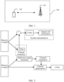
- This application relates to the field of wireless communication technologies, and in particular, to a signal processing method and an apparatus.
- Artificial intelligence technologies have been successfully applied in fields of image processing and natural language processing, and increasingly mature artificial intelligence technologies will play an important role in promoting evolution of mobile communication network technologies.
- the artificial intelligence technologies are mainly applied to a network layer, a physical layer, and the like.
- modules at the physical layer for example, modules for signal processing such as coding, modulation, multiple-input multiple-output precoding, and beamforming, are mostly replaced by using the artificial intelligence technology.
- Main advantages of the artificial intelligence technology are reducing an operation delay, improving algorithm performance, and the like.
- performance achieved by an independent optimization algorithm of each module is close to an upper bound of the performance. Therefore, a gain obtained through only module replacement is limited.
- Embodiments of this application provide a signal processing method and an apparatus, to improve signal processing performance.
- a signal processing method may be performed by a communication apparatus, or may be performed by a chip having a function similar to that of a communication apparatus.
- the communication apparatus may be a network device or a terminal device.
- the communication apparatus maps an input signal to N1 resource patches (resource patches, RPs), where the RP includes one or more resource elements (resource elements, REs), and each RP includes one signal vector determined based on the input signal.
- the communication apparatus inputs N1 signal vectors to an input layer of a neural network for dimension increase processing, to obtain N2 high-dimensional signal vectors.
- the communication apparatus inputs the N2 high-dimensional signal vectors to an interaction layer of the neural network, to obtain a feature between the N2 high-dimensional signal vectors and a feature of each high-dimensional signal vector.
- the communication apparatus inputs the feature between the N2 high-dimensional signal vectors and the feature of each high-dimensional signal vector to an output layer of the neural network for an operation, to obtain an output signal vector.
- the feature of each signal vector and the feature between the signal vectors are obtained via the interaction layer. Because the feature of the signal vector and the feature between the signal vectors are independent of a dimension of the signal vector, complexity of signal processing can be reduced. In addition, a quantity of signal vectors input to the interaction layer may be changed, so that scalability of signals in different dimensions can be implemented.
- the interaction layer of the neural network includes at least one interaction module group, and each interaction module group includes a first interaction module and a second interaction module.
- the first interaction module is configured to obtain the feature between the N2 high-dimensional signal vectors
- the second interaction module is configured to obtain the feature of each high-dimensional signal vector.
- An interaction module group l includes a first interaction module l _1 and a second interaction module l_ 2, where l ⁇ L.
- input of the first interaction module l _1 is any one of the high-dimensional signal vector, output of a second interaction module l -1_2 in an interaction module l -1, or output of a first interaction module l -1_1 in an interaction module group l -1, and input of the second interaction module l_ 2 is output of the first interaction module l _1.
- input of the second interaction module l _2 is any one of the high-dimensional signal vector, output of a first interaction module l -1_1 in an interaction module group l -1, or output of a second interaction module l -1_2 in an interaction module group l -1, and input of the first interaction module l _1 is output of the second interaction module l _2.
- a sequence of the first interaction module and the second interaction module in each interaction module group is not specifically limited. Because a dimension of input of the interaction layer is the same as a dimension of output of the interaction layer, L layers of iterations may be performed at the interaction layer. In other words, L interaction module groups may be connected to each other, so that the L layers of iterations are performed at the interaction layer.
- a plurality of layers of iterations at the interaction layer are implemented via a plurality of interaction module groups, so that a performance gain of the neural network can be obtained.
- the first interaction module includes an operation of an attention layer
- the second interaction module includes an operation of a fully connected layer
- a neural network parameter according to the foregoing solution is independent of the dimension of the input signal vector, so that scalability of the neural network is implemented.
- a correlation between any two signal vectors may be extracted via the attention layer, and a larger quantity of parameters can be obtained, so that the neural network can be applied to more communication scenarios.
- Q, K, and V represent results obtained by performing three linear transformations on input S, Q represents a query vector, W Q represents a query vector weight, K represents a keyword vector, W K represents a keyword vector weight, V represents a value vector, and W V represents a value vector weight.
- y is the feature of each high-dimensional signal vector
- f is an activation function
- W M and b are obtained through training
- W M represents a weight of the fully connected layer
- b represents an offset of the fully connected layer
- x is input of the fully connected layer.
- an operation performed by the first interaction module is based on a first matrix, and the first matrix is an N2 ⁇ N2 matrix.
- An operation performed by the second interaction module is based on a second matrix, the second matrix is a d k ⁇ d k matrix, and d k is a dimension of the high-dimensional signal vector.
- independent transformation of the input signal vector is implemented.
- the feature between the signal vectors can be obtained by using the first matrix, and the feature of each signal vector can be obtained by using the second matrix. Therefore, scalability of the neural network is implemented by expanding the matrix.
- a correlation between any two signal vectors may be extracted by using the first matrix, and a larger quantity of parameters can be obtained, so that the neural network can be applied to more communication scenarios.
- elements on a main diagonal of the first matrix are the same. Elements of the first matrix other than the elements on the main diagonal are the same.
- an element on the main diagonal may represent obtaining a feature of the element.
- the element on the main diagonal is for obtaining a feature of a signal vector
- an element other than the element on the main diagonal represents obtaining a feature between a signal vector and another signal vector.
- the first matrix is obtained through calculation based on the input N2 high-dimensional signal vectors.
- the first matrix when the elements on the main diagonal of the first matrix are the same, the first matrix can be expanded by expanding the elements on the main diagonal, to implement scalability of the neural network.
- the interaction layer of the neural network includes a graph neural network
- the communication apparatus sets each of the N2 high-dimensional signal vectors to a state of a node in the graph neural network at a 0 th time, where each node corresponds to one high-dimensional signal vector.
- the feature between the N2 high-dimensional signal vectors is an aggregated state of an adjacent node of each node in the graph neural network obtained at a Z th time, and a state of each high-dimensional signal vector is a state of each node at the Z th time. It may be understood that the state of each node at the Z th time is obtained based on the aggregated state obtained at the Z th time and a state of each node at a (Z-1) th time, where Z is an integer greater than or equal to 1.
- the feature between the high-dimensional signal vectors and the feature of each high-dimensional signal vector may be obtained via the graph neural network, and the obtained feature is independent of the dimension of the input signal vector, and has scalability.
- a quantity of REs included in each RP is determined based on a computing resource available to the communication apparatus and/or a physical resource occupied by the input signal.
- an RP configuration includes three parameters that respectively correspond to a frequency n_F, a time domain n_T, and a space domain n_L.
- the RP configuration is associated with at least one of a time domain resource, a frequency domain resource, and a space domain resource that are occupied by the input signal, and the computing resource available to the communication apparatus.
- configuration information of the RP is indicated by a network device.
- the communication apparatus may obtain configuration information of the resource patch from the network device in an uplink channel measurement phase, so that a size of each resource patch can be determined.
- the communication apparatus sends configuration information of a recommended RP to the network device.
- the configuration information of the RP that is obtained by the communication apparatus can better conform to an actual situation of the communication apparatus.
- an operation performed by the interaction layer is further based on a task vector, and the task vector is for obtaining high-dimensional task information.
- the output signal vector further includes target task information, and the target task information is obtained based on the high-dimensional task information.
- a task layer may be further set in the neural network. An operation of the task layer is for executing a task.
- One or more task layers may be set, and an operation of each task layer corresponds to one task.
- the neural network may be applied to a large quantity of communication scenarios by using the task vector and the task layer, for example, scenarios such as signal-to-noise ratio estimation, terminal speed estimation, channel delay spread estimation, channel type detection, channel estimation, channel coding, or channel decoding.
- scenarios such as signal-to-noise ratio estimation, terminal speed estimation, channel delay spread estimation, channel type detection, channel estimation, channel coding, or channel decoding.
- the operation performed by the interaction layer is further based on a trainable vector, and the trainable vector is for obtaining global information of the N2 high-dimensional signal vectors.
- the output signal vector is determined based on the feature between the N2 high-dimensional signal vectors, the feature of each high-dimensional signal vector, and the global information.
- prior information may be obtained for the trainable vector in a training phase, and the global information of the N2 high-dimensional signal vectors may be obtained by using the trainable vector, so that inference performance of the neural network can be improved.
- the input signal includes data received by the communication apparatus
- the output signal vector includes a log-likelihood ratio of the data.
- the communication apparatus may decode the received data based on the log-likelihood ratio.
- the input signal includes a modulation symbol
- the output signal vector includes a transmission symbol.
- a waveform may be generated when the transmission symbol passes through a waveform generation module.
- the communication apparatus may transmit, through an antenna, a signal corresponding to the waveform.
- the input signal includes a to-be-encoded bit
- the output signal vector includes an encoded bit or a transmission symbol.
- the communication apparatus may encode the to-be-encoded bit based on the foregoing neural network.
- the communication apparatus may map the to-be-encoded bit to the transmission symbol based on the neural network.
- an embodiment of this application provides a communication apparatus.
- the apparatus may be a terminal device or a network device, or may be a chip or a module used in a terminal device or a network device.
- the apparatus has a function of implementing the method according to any implementation of the first aspect.
- the function may be implemented by hardware, or may be implemented by hardware executing corresponding software.
- the hardware or the software includes one or more modules or units corresponding to the foregoing function.
- the communication apparatus may include a transceiver unit and a processing unit.
- the processing unit is configured to: map the input signal to N1 resource patches RPs, where the RP includes one or more resource elements REs, and each RP includes one signal vector determined based on the input signal; input N1 signal vectors to an input layer of a neural network for dimension increase processing, to obtain N2 high-dimensional signal vectors; input the N2 high-dimensional signal vectors to an interaction layer of the neural network, to obtain a feature between the N2 high-dimensional signal vectors and a feature of each high-dimensional signal vector; and input the feature between the N2 high-dimensional signal vectors and the feature of each high-dimensional signal vector to an output layer of the neural network for an operation, to obtain an output signal vector.
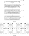
- S301 Map an input signal to N1 resource patches (resource patches, RPs), where N1 is a positive integer.
- the input signal in S301 may be a received signal, for example, may be a signal received from a network device.
- the input signal in S301 may be a signal obtained from a higher layer of a communication apparatus, for example, a physical layer.
- the input signal when the method is applied to a transmitting end, the input signal may be a communication signal vector such as a bit or a symbol.
- the input signal when the method is applied to a receiving end, the input signal may be a symbol received at the receiving end; or the input signal may be a communication signal vector representing a probability, such as a log-likelihood ratio of a symbol.
- N2 Input N1 signal vectors to an input layer of a neural network for dimension increase processing, to obtain N2 high-dimensional signal vectors, where N2 is a positive integer. It may be understood that N2 and N1 herein may be the same or different, and N2 may be greater than N1 or may be less than N1.
- the input layer of the neural network may perform dimension increase processing on the signal vector to obtain the high-dimensional signal vector.
- the input layer of the neural network may change a 16-dimensional signal vector to a 256-dimensional signal vector.
- a dimension of the high-dimensional signal vector is described as d k , where d k is a positive integer.
- S303 Input the N2 high-dimensional signal vectors to an interaction layer of the neural network, to obtain a feature between the N2 high-dimensional signal vectors and a feature of each high-dimensional signal vector.
- the interaction layer of the neural network may be used for obtaining the feature of the high-dimensional signal vector.
- the interaction layer of the neural network may be used for obtaining the feature of each high-dimensional signal vector, or may obtain the feature between the high-dimensional signal vectors.
- the feature between the high-dimensional signal vectors includes a feature between every two high-dimensional vectors. For example, four high-dimensional signal vectors are obtained in S302: S1, S2, S3, and S4.
- the interaction layer of the neural network may obtain a feature of S1, a feature of S2, a feature of S3, and a feature of S4; and a feature from S1 to S2, a feature from S1 to S3, a feature from S1 to S4, a feature from S2 to S1, a feature from S2 to S3, a feature from S2 to S4, and so on. Therefore, the features between the four high-dimensional vectors may be obtained.
- the output layer of the neural network may obtain an encoded code block based on the feature between the N2 high-dimensional signal vectors and the feature of each high-dimensional signal vector. That is, the output signal vector is the encoded code block.
- the input signal in S301 is a log-likelihood ratio of a symbol
- the corresponding output signal vector may be in a bit form.
- input of an input layer is N signal vectors x formed through resource patch mapping, which are respectively x 1 to x N .
- the input layer performs dimension increase processing on the N signal vectors, to obtain N high-dimensional signal vectors S: S 1 to S N .
- a dimension of each high-dimensional signal vector is d k .
- a dimension of output of the input layer is dimensions N ⁇ d k .
- Input of an interaction layer is the output of the input layer, and the interaction layer may obtain a feature of each high-dimensional signal vector in S 1 to S N . It may be understood that obtaining the feature of each high-dimensional signal vector may be considered as an operation performed by the interaction layer on a dimension d k in the dimensions N ⁇ d k .
- the interaction layer may further obtain a feature between high-dimensional signal vectors in S 1 to S N . It may be understood that obtaining the feature between the high-dimensional signal vectors in S 1 to S N may be considered as an operation performed by the interaction layer on a dimension N in the dimensions N ⁇ d k . Therefore, output of the interaction layer is also (N ⁇ d k )-dimensional. The feature of each high-dimensional signal vector and features h 1 to h N between the N high-dimensional signal vectors may be obtained via the interaction layer. Input of an output layer is the output of the interaction layer, and the output layer may output signal vectors o 0 to o N based on h 1 to h N .
- a dimension of the input of the interaction layer is the same as the dimension of the output of the interaction layer. Therefore, a quantity of signal vectors input to the interaction layer is the same as a quantity of signal vectors output by the interaction layer.
- the input layer may increase or decrease a quantity of input signal vectors.
- the output layer may also increase or decrease the feature of each input high-dimensional signal vector and the feature between the N high-dimensional signal vectors.
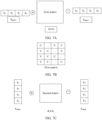
- the interaction layer may include at least one interaction module group.
- An interaction module group l may include a first interaction module l _1 and a second interaction module l_2.
- the first interaction module l _1 may be configured to obtain the feature between the N2 high-dimensional signal vectors
- the second interaction module l _2 may be configured to obtain the feature of each high-dimensional signal vector. It may be understood that a sequence of the first interaction module and the second interaction module in each interaction module group is not specifically limited. Because the dimension of the input of the interaction layer is the same as the dimension of the output of the interaction layer, L layers of iterations may be performed at the interaction layer. In other words, L interaction module groups may be connected to each other, so that the L layers of iterations are performed at the interaction layer. l is an integer greater than or equal to 1 and less than L.
- a first interaction module 1_1 is before a second interaction module 1_2. In other words, output of the first interaction module 1_1 is used as input of the second interaction module 1_2.
- a first interaction module 2_1 is after a second interaction module 2_2. In other words, output of the second interaction module 2_2 is used as input of the first interaction module 2_1.
- input of a first interaction module l _1 may be a high-dimensional signal vector, or may be output of a second interaction module l_ 2.
- Input of the second interaction module l _2 may be output of the first interaction module l_ 1, or may be output of a second interaction module l -1_2.
- a first interaction module 1_1 is before a second interaction module 1_2. In other words, output of the first interaction module 1_1 is used as input of the second interaction module 1_2.
- a first interaction module 2_1 is before a second interaction module 2_2. In other words, output of the first interaction module 2_1 is used as input of the second interaction module 2_2. It can be learned from FIG. 5B that input of a first interaction module l _1 may be a high-dimensional signal vector, or may be output of a second interaction module l -1_2. Input of a second interaction module l _2 may be output of the first interaction module l_ 1.
- a first interaction module 1_1 is after a second interaction module 1_2. In other words, output of the second interaction module 1_2 is used as input of the first interaction module 1_1.
- a first interaction module 2_1 is before a second interaction module 2_2. In other words, output of the first interaction module 2_1 is used as input of the second interaction module 2_2. It can be learned from FIG. 5C that input of a first interaction module l_ 1 may be output of a second interaction module l_ 2, or may be output of a first interaction module l -1_1. Input of the second interaction module l _2 may be a high-dimensional signal vector, or may be output of the first interaction module l_ 1.
- a first interaction module 1_1 is after a second interaction module 1_2. In other words, output of the second interaction module 1_2 is used as input of the first interaction module 1_1.
- a first interaction module 2_1 is after a second interaction module 2_2. In other words, output of the second interaction module 2_2 is used as input of the first interaction module 2_1. It can be learned from FIG. 5D that input of a first interaction module l _1 may be output of a second interaction module l_ 2. Input of the second interaction module may be a high-dimensional signal vector, or may be output of a first interaction module l -1_1.
- the interaction layer may further include a third interaction module.
- the third interaction module may be configured to obtain a feature of the high-dimensional signal vector in a dimension y and a correlation, or the third interaction module may be configured to perform dimension transformation on the high-dimensional signal vector, for example, change the high-dimensional signal vector from a three-dimensional vector into a two-dimensional vector. It may be understood that a sequence relationship among the third interaction module, the first interaction module, and the second interaction module may not be specifically limited. For details, refer to the foregoing implementation of the sequence relationship between the first interaction module and the second interaction module.
- a plurality of layers of iterations at the interaction layer are implemented via a plurality of interaction module groups, so that a performance gain of the neural network can be obtained.
- the first interaction module may include an operation of an attention layer
- the second interaction module may include an operation of a fully connected layer.
- the operation of the interaction layer may include the operation of the attention layer and the operation of the fully connected layer.
- S N ⁇ d k is input of the attention layer, where N may be understood as a quantity of high-dimensional signal vectors S, and d k is a dimension of each high-dimensional signal vector S.
- ATT(Q, K, V) is output of the attention layer, and represents a correlation between any two high-dimensional signal vectors.
- Q, K, and V represent results obtained by performing three linear transformations on input S, Q represents a query vector, W Q represents a query vector weight, K represents a keyword vector, W K represents a keyword vector weight, V represents a value vector, and W V represents a value vector weight. It can be learned that the input of the attention layer is (N ⁇ d k )-dimensional.
- W Q , W K , and W V each have a plurality of groups of values. It may be understood that parameters of attention layers of each interaction module group may be different.
- W Q , W K , and W V may be trained in a gradient backpropagation manner.
- initial parameters of W Q , W K , and W V may be set to random numbers, and high-dimensional signal vectors used during training are processed via the attention layer, to obtain output signal vectors used during the training.
- a training gradient is obtained by using a known output signal vector and the output signal vector used during the training, and the gradient is back propagated to the attention layer, so that W Q , W K , and W V are adjusted.
- W Q , W K , and W V may be trained for a plurality of times, to obtain trained W Q , W K , and W V .
- the fully connected layer performs an operation on each high-dimensional signal vector independently, and each high-dimensional signal vector shares a parameter of the fully connected layer.
- y represents output of the fully connected layer
- x represents input of the fully connected layer
- f is an activation function.
- the activation function may be one of a linear function, a pseudo-inverse function, an inverse function, a Sigmoid (Sigmoid) function, a Softmax (Softmax) function, a Relu (Relu) function, a Gelu (Gelu) function, and the like.
- W M represents a weight of the fully connected layer
- b represents an offset of the fully connected layer.
- W M and b are trained parameters. For training manners, refer to the foregoing implementation of the training manners of W Q , W K , and W V . It may be understood that parameters of fully connected layers of each interaction module group may be different.
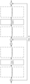
- FIG. 6 shows an example of an interaction layer.
- a dashed box labeled normalization may represent an optional position for normalization operation.
- the normalization operation may be set before an attention layer, after the attention layer, before a fully connected layer, and/or after the fully connected layer.
- an interaction layer may include one or more normalization operations.
- the normalization operation may normalize each feature dimension of a batch of data. In other words, the normalization operation may be batch normalization (batch normalization) performed on the high-dimensional signal vector. Alternatively, the normalization operation may normalize all feature dimensions of a group of data. In other words, the normalization operation may be layer normalization (layer normalization) performed on the high-dimensional signal vector.
- x represents input of the normalization operation
- y represents output of the normalization operation
- ⁇ represents an average value calculated based on x
- ⁇ represents a variance calculated based on x
- ⁇ is a preset minimum value to prevent 0 from appearing in a denominator
- ⁇ and ⁇ are trained parameters.
- Input of a first normalization operation may be N high-dimensional signal vectors.
- Output of the first normalization operation may be N normalized high-dimensional signal vectors.
- Input of the attention layer may be the output of the first normalization operation.
- For an operation of the attention layer refer to the foregoing formula (1).
- the attention layer may obtain a feature between the N high-dimensional signal vectors.
- Output of the attention layer may be the feature between the N high-dimensional signal vectors. It can be learned from FIG. 6 that input of a second normalization operation may be the output of the attention layer and the N high-dimensional signal vectors.
- the second normalization operation may normalize the N high-dimensional signal vectors and features of the N high-dimensional signal vectors, and output of the second normalization operation may be normalized a feature between the N high-dimensional signal vectors and the N high-dimensional signal vectors.
- a dimension of the output of the normalization operation is the same as a dimension of output of the fully connected layer.
- Input of the fully connected layer may be output of the second normalization operation.
- the fully connected layer may obtain the features of the N high-dimensional signal vectors.
- the output of the fully connected layer may be the feature between the N high-dimensional signal vectors and the features of the N high-dimensional signal vectors.
- input of a third normalization operation may be the N high-dimensional signal vectors, the feature between the N high-dimensional signal vectors, and the features of the N high-dimensional signal vectors.
- the interaction layer shown in FIG. 6 may be iterated for L times.
- an iterative operation may be stopped based on an actual situation.
- a convergence condition may be set, for example, a convergence in which an average output error between an l th iteration and an ( l +1) th iteration is less than a threshold, where l is an integer greater than or equal to 1 and less than L.
- input and output of each operation at the interaction layer may be considered as a matrix, and the matrix may be (N ⁇ d k )-dimensional.
- input of a second normalization layer may be a matrix obtained by adding the output of the attention layer and the N high-dimensional signal vectors. That is, the input of the second normalization operation is still a (N ⁇ d k )-dimensional matrix.
- each operation of the neural network for example, an input layer, a first interaction module and a second interaction module in the interaction layer, and an output layer, may be set as an operation of a fully connected neural network.
- An operation of the first interaction module in the interaction layer may be applying a self-focusing mechanism to output of a plurality of fully connected neural networks.
- the interaction layer is set based on Manner 1, so that independent transformation of the input signal vector is implemented.
- a neural network parameter is independent of the dimension of the input signal vector.
- scalability of the neural network is implemented.
- a correlation between any two signal vectors may be extracted via the attention layer, and a larger quantity of parameters can be obtained, so that the neural network can be applied to more communication scenarios.
- An operation performed by the first interaction module may be based on a first matrix
- an operation performed by the second interaction module may be based on a second matrix.
- the operation of the interaction layer may include an operation based on the first matrix and an operation based on the second matrix.
- the first matrix may be an N ⁇ N matrix.
- the first matrix may be a trained matrix.
- For training manners of the first matrix refer to the foregoing training manners of W Q , W K , and W V .
- elements on a main diagonal of the first matrix are the same and are U, and elements that are not on the main diagonal are the same and are V
- the element U on the main diagonal represents obtaining a feature of a signal vector
- the element V other than the element on the main diagonal represents obtaining features of a signal vector and another signal vector.
- the first matrix is a 3 ⁇ 3 matrix.
- an element in the first row and the first column is U, and the element is for obtaining a feature of a first high-dimensional signal vector; an element in the first row and the second column is V, and the element is for obtaining features of the first high-dimensional signal vector and a second high-dimensional signal vector; and an element in the first row and the third column is V, the element is for obtaining features of the first high-dimensional signal vector and a third high-dimensional signal vector, and so on.
- the first matrix is the N ⁇ N matrix, to be specific, the first matrix is expanded as a quantity of input high-dimensional signal vectors increases, the first matrix has scalability.
- the first matrix is calculated based on N input high-dimensional signal vectors.
- the first matrix may be f(R S ), f(C S ), f(cos S ), or the like, R S represents an autocorrelation matrix of S, C S represents an autocovariance matrix of S, cos S represents calculating a cosine similarity between every two of high-dimensional signal vectors S, and f represents a normalization or non-linear operation.
- S may represent an input high-dimensional signal vector.
- the first matrix may be in a form of a fully connected neural network.
- W S and b are trained parameters.
- For training manners refer to the foregoing training manners of W Q , W K , and W V .
- f is an activation function.
- W S may be a weight, and b may be an offset.
- b represents the offset of the fully connected neural network. Values of b in different modules may be different, and b is specifically determined based on an actual training result. For example, a value of b in h S may be different from a value of b in the foregoing formula (2).
- the second matrix may be a d k ⁇ d k matrix.
- the second matrix may be a trained parameter.
- f may alternatively be calculating a maximum value, a minimum value, an average value, or the like. This is not specifically limited in this application.
- W and b are trained parameters.
- For training manners refer to the foregoing training manners of W Q , W K , and W V .
- f is an activation function.
- a plurality of first matrices and a plurality of second matrices may also be concatenated in an iteration.
- the operation of the first interaction module may be an operation based on the plurality of first matrices
- the operation of the second interaction module may be an operation based on the plurality of second matrices.
- FIG. 8 shows an example of an interaction layer.
- a dashed box labeled normalization may represent an optional position for normalization operation.
- For setting of the normalization operation refer to the related descriptions in FIG. 6 . Details are not described herein again.
- a matrix transpose operation may be performed on an input high-dimensional signal vector. This is because input of the interaction layer is (N ⁇ d k )-dimensional, and the first interaction module performs an operation on an N dimension. Therefore, the matrix transpose operation may be performed on the input high-dimensional signal vector. In other words, the (N ⁇ d k )-dimensional high-dimensional signal vector is transposed into (d k ⁇ N)-dimensional.
- the interaction layer is set based on Manner 2, so that independent transformation of the input signal vector is implemented.
- the feature between the signal vectors can be obtained by using the first matrix, and the feature of each signal vector can be obtained by using the second matrix. Therefore, scalability of the neural network is implemented by expanding the matrix.
- a correlation between any two signal vectors may be extracted by using the first matrix, and a larger quantity of parameters can be obtained, so that the neural network can be applied to more communication scenarios.
- the operation of the interaction layer may be an operation of a graph neural network.
- the following provides specific descriptions.
- 0 in S N 0 may represent an initial state of the high-dimensional signal vector.
- a communication apparatus may use each high-dimensional signal vector as a node in the graph neural network. That is, the graph neural network may have N nodes. In other words, the communication apparatus may set each high-dimensional signal vector to an initial state of the node in the graph neural network, for example, a state of the 0 th iteration.
- One high-dimensional signal vector may correspond to one node.
- the first interaction module and the second interaction module are not explicitly distinguished in structure, and the first interaction module and the second interaction module are distinguished in operation steps of the graph neural network.
- FIG. 9 shows an example of an interaction layer according to an embodiment of this application.
- S 1 , S 2 , S 3 , and S 4 may be nodes of the graph neural network.
- An operation of a first interaction module may be that S N obtains an aggregated state of other adjacent nodes.
- S N represents any node in the graph neural network.
- S 1 may obtain an aggregated state of S 2 , S 3 , and S 4 .
- the operation of the first interaction module may satisfy the following formula (4):
- S N v K AGGREGATE K S u K ⁇ 1 , ⁇ u ⁇ N v
- An aggregate function may be calculating a maximum value, a minimum value, an average value, a sum, or the like.
- Z represents a quantity of iterations
- (v) represents another node adjacent to a node v
- S N v K represents an aggregated state of the another node that is connected to the node v and that is in a Z th iteration
- S u K ⁇ 1 represents a state of a (Z-1) th iteration of the another node adjacent to the node v, where Z is an integer greater than or equal to 1.
- Z may be a preset quantity of iterations. It may be understood that a state of the node at a 0 th time may be a high-dimensional signal vector corresponding to the node.
- An operation of a second interaction module may be that S N updates a state of S N based on the aggregated state of the another adjacent node at the Z th time and a state of S N at the Z th time.
- ⁇ is an activation function
- Z represents a quantity of iterations, where Z is an integer greater than or equal to 1.
- Z may be a preset quantity of iterations.
- w K represents a weight of a Z th iteration
- S v K ⁇ 1 represents a state of the node v in a (Z-1) th iteration
- S N v K represents an aggregated state of another node that is connected to the node v and that is in the Z th iteration
- a concatenate function may represent concatenation, that is, concatenates S N v K and S v K ⁇ 1 . It may be understood that the concatenation may be understood as splicing two vectors into one vector.
- the graph neural network may output a state of each node at the Z th time and an aggregated state that is of an adjacent node and that is obtained by each node at the Z th time. It may be understood that a dimension of the state of each node that is output by each node at the Z th time and the aggregated state of the adjacent node that is obtained by each node at the Z th time is d k , and a dimension of a state of each node that is output by N nodes at the Z th time and an aggregated state that is of an adjacent node that is obtained by each node at the Z th time is N ⁇ d k .
- the state of each node at the Z th time may be understood as a feature of each high-dimensional signal vector.
- the aggregated state that is of the adjacent node and that is obtained by each node at the Z th time may be understood as a feature between high-dimensional signal vectors.
- the interaction layer is set based on Manner 3.
- the feature between the high-dimensional signal vectors and the feature of each high-dimensional signal vector may be obtained via the graph neural network, and the obtained feature is independent of a dimension of an input signal vector, so that scalability of the neural network is implemented.
- the interaction layer of the neural network according to this embodiment of this application is set in any one of Manner 1 to Manner 3, so that the feature between the N high-dimensional signal vectors and the feature of each high-dimensional signal vector can be obtained, and the output signal vector is obtained by the operation performed at the output layer.
- the communication apparatus may determine a quantity of REs included in the RP in S301. That is, the communication apparatus may determine a size of the RP in S301.
- An RP configuration includes three parameters that respectively correspond to a frequency n_F, a time domain n_T, and a space domain n_L.
- the RP configuration may be associated with at least one of a physical resource occupied by an input signal, for example, a time domain resource, a frequency domain resource, and a space domain resource, and a computing resource available to the communication apparatus. For example, a larger computing resource of the communication apparatus indicates a smaller RP size (n_F ⁇ n_T ⁇ n_L).
- a higher correlation among the time domain, the space domain, and the frequency domain occupied by the input signal indicates a larger parameter configuration of a corresponding domain. For example, assuming that a correlation between the time domain resource in the physical resource occupied by the input signal and the RP configuration is the highest, a value of n_T in the RP configuration is the largest. It may be understood that correlations between the time domain resource, the frequency domain resource, and the space domain resource that are occupied by the input signal and the RP configuration may be determined based on an empirical value. For example, if a channel occupied by the input signal changes slowly in terms of time, the correlation between the RP configuration and the time domain resource is higher. If more channel multipaths are occupied by the input signal and greater selectivity is in frequency domain, a correlation between the RP configuration and the frequency domain resource is lower.
- the RP configuration may be indicated by a network device.
- the communication apparatus may determine the RP configuration in a channel measurement phase.
- S1001A A network device sends a channel measurement reference signal to a terminal device.
- the terminal device receives the channel measurement reference signal from the network device.
- the network device may send a channel state information reference signal (channel state information reference signal, CSI-RS) to the terminal device.
- CSI-RS channel state information reference signal
- S1002A The terminal device performs channel measurement based on the channel measurement reference signal.
- the terminal device measures quality of a downlink channel based on the channel measurement reference signal, for example, measures reference signal received power (reference signal received power, RSRP) of the channel measurement reference signal.
- reference signal received power reference signal received power
- the terminal device sends configuration information of a recommended resource patch to the network device based on a result of the channel measurement and a computing resource of the terminal device.
- the network device receives the configuration information of the recommended resource patch from the terminal device.
- the terminal device may send recommended resource patch information (recommended patch information, RPI) to the network device.
- RPI recommended patch information
- the RPI may include the configuration information of the resource patch recommended by the terminal device to the network device.
- S1004A The network device sends the configuration information of the resource patch to the terminal device.
- the terminal device receives the configuration information of the resource patch from the network device.
- the network device may send resource patch information (patch information, PI) to the terminal device.
- the PI may include the configuration information of the resource patch that is indicated by the network device.
- the terminal device may obtain the configuration information of the resource patch from the network device in the downlink channel measurement phase, so that a size of each resource patch can be determined.
- the terminal device may recommend the configuration information of the resource patch to the network device, so that the configuration information of the resource patch that is determined by the network device can better conform to an actual situation of the terminal device.
- S1001B A terminal device sends a channel measurement reference signal to a network device.
- the network device receives the channel measurement reference signal from the terminal device.
- the terminal device may send an uplink sounding reference signal (sounding reference signal, SRS) to the network device.
- SRS sounding reference signal
- S1002B The network device performs channel measurement based on the channel measurement reference signal.
- the network device measures quality of an uplink channel based on the channel measurement reference signal, for example, measures RSRP of the channel measurement reference signal.
- S1003B The network device sends configuration information of a resource patch to the terminal device.
- the terminal device receives the configuration information of the resource patch from the network device.
- the network device may send PI to the terminal device.
- the terminal device may obtain the configuration information of the resource patch from the network device in an uplink channel measurement phase, so that a size of each resource patch can be determined.
- Table 1 Optional RPI or PI configurations (R)PI Optional configuration n_F 1, 2, 4, 6, 8, 12, 24, 48, 96 n_T 1, 2, 4, 6, 12, 24, 48, 96 (norm.)/1, 2, 4, 7, 14, 28, 56, 112 (ext.) n_L 1, 2, 4, 8, 16, 32, 64, 128
- a configuration 1 corresponding to n_F may be considered as that the RPI or the PI may include one RE in frequency domain
- a configuration 1 corresponding to n_T may be considered as that the RPI or the PI includes one symbol in time domain
- a configuration 1 corresponding to n_L may be considered as that the RPI or the PI includes one stream in space domain.
- an operation performed by an interaction layer is alternatively based on a task vector.
- the task vector may be for obtaining high-dimensional task information.
- the task vector may be used as input of the interaction layer, and output of the interaction layer may be the high-dimensional task information.
- each task vector may correspond to one task, for example, tasks such as signal-to-noise ratio estimation, UE speed estimation, channel delay spread estimation, channel type detection, and channel estimation.
- the task vector S T may be a pre-trained parameter.
- the task vector S T may be trained based on parameters of a first interaction module and a second interaction module.
- the communication apparatus may be an initialized task vector S T , and the initialized task vector S T may be a random number.
- the communication apparatus may freeze parameters of an input layer, the first interaction module, the second interaction module, and an output layer, and train the task vector S T based on the training manners of W Q , W K , and W V .
- freezing the parameters of the input layer, the first interaction module, the second interaction module, and the output layer may be understood as that the parameters of the input layer, the first interaction module, the second interaction module, and the output layer do not change.
- the communication apparatus may train the task vector S T when the parameters of the input layer, the first interaction module, the second interaction module, and the output layer do not change.
- a task layer may be further set in a neural network.
- An operation of the task layer is for executing a task.
- One or more task layers may be set, and an operation of each task layer corresponds to one task.
- r 1 to r N are input of an input layer, and S 1 to S N are output of the input layer and input of an interaction layer.
- the interaction layer may obtain a feature of each high-dimensional signal vector in S 1 to S N and a feature between S 1 to S N .
- Output of the interaction layer is h 1 to h N .
- a task vector S T may obtain high-dimensional task information h T via the interaction layer.
- Input of an output layer is h 1 to h N
- input of the task layer is h T .
- the output layer may obtain output signal vectors I 1 to I N based on h 1 to h N .
- the output signal vector may further include T, namely, target task information.
- the target task information is output of the task layer, and is obtained by the task layer based on h T .
- an operation performed by an interaction layer may be alternatively based on a trainable vector.
- the trainable vector may be used for obtaining global information of N high-dimensional signal vectors.
- For training manners of the trainable vector refer to the training manners of W Q , W K , and W V .
- the trainable vector is represented by S G .
- S G may obtain h G via the interaction layer, and h G may be concatenated to each of output h 1 to h N of the interaction layer.
- r 1 to r N are input of an input layer, and S 1 to S N are output of the input layer and input of the interaction layer.
- the interaction layer may obtain a feature of each high-dimensional signal vector in S 1 to S N and a feature between S 1 to S N .
- the global information h G may also be concatenated to high-dimensional task information h T .
- the global information h G may be concatenated before the high-dimensional task information h T .
- the global information h G may alternatively be concatenated after the high-dimensional task information h T . It may be understood that a manner of concatenating the global information and the high-dimensional task information may be the same as the foregoing manner of concatenating the feature between the global information and the high-dimensional signal vector output by the interaction layer and the feature of the high-dimensional signal vector.
- Input of an output layer is h 1 to h N
- input of a task layer is h T
- the output layer may obtain output signal vectors I 1 to I N based on h 1 to h N .
- the output signal vector may further include T, namely, target task information.
- the target task information is output of the task layer, and is obtained by the task layer based on h T .
- FIG. 12 is an example of a receiver of a communication apparatus according to an embodiment of this application.
- the communication apparatus may receive data from another communication apparatus.
- Input of the receiver may be a received signal r obtained after operations such as cyclic prefix (cycle prefix, CP) removal and fast Fourier transform (fast fourier transform, FFT) are performed on a physical baseband signal.
- the communication apparatus may map, to N RPs, the signal r obtained after the operations such as the CP removal and the FFT are performed.
- Each RP includes one signal vector. As shown in FIG.
- an input layer performs dimension increase processing on r 1 to r N , to obtain high-dimensional signal vectors S 1 to S N .
- a feature of a high-dimensional signal vector and features h 1 to h N between the high-dimensional signal vectors are obtained after S 1 to S N pass through the interaction layer.
- log-likelihood ratios I 1 to I N corresponding to each transmission bit are obtained.
- an operation of the interaction layer may further be based on a trainable vector S G .
- Global information h T of the high-dimensional signal vector may be obtained after S G passes via the interaction layer, and the global information h T is concatenated to h 1 to h N as output of the output layer.
- the receiver may directly and jointly detect a signal of an entire frame.
- the receiver may map the signal of the entire frame to N resource patches by using a resource patch, and increase a dimension of a signal included in each resource patch to d k , and a feature of each high-dimensional signal vector and a feature between N high-dimensional signal vectors are obtained by using a neural network. Therefore, complexity of jointly detecting the signal of the entire frame can be reduced, and better performance can be obtained.
- the receiver does not display a channel estimation process and a channel equalization process, so that the complexity of signal processing can be reduced.
- FIG. 13 shows a change of a training loss of a neural network in a training process, and compares performance 1301 with S G and performance 1302 without s G in a neural network structure.
- a vertical coordinate indicates a value of a loss function, and a faster decrease of the value of the vertical coordinate represents a faster convergence speed.
- a horizontal coordinate indicates a quantity of parameter update times. It can be learned that when the neural network does not include s G , because a quantity of parameters of the neural network is smaller, the convergence speed is faster; and when the neural network includes s G , the performance finally achieved is better.
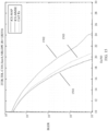
- FIG. 14 compares performance of a receiver that uses a neural network according to this embodiment of this application in a one transmitter one receiver configuration.
- a horizontal coordinate indicates a signal-to-noise ratio
- a vertical coordinate indicates a bit error rate.
- a curve 1401 corresponding to ideal channel estimation represents performance of the receiver in an ICE condition.
- a curve 1402 corresponding to minimum mean square error channel estimation represents performance of the receiver in an MMSE condition, and the performance of the ICE may be considered as an upper limit of the performance. It can be learned from FIG. 14 that performance 1403 of the receiver that uses the neural network according to this embodiment of this application is better than that of the MMSE, and is close to the upper limit of the performance.
- FIG. 15 compares performance of a receiver that uses a neural network according to this embodiment of this application in a two transmitter two receiver configuration.
- a horizontal coordinate indicates a signal-to-noise ratio
- a vertical coordinate indicates a bit error rate.
- a curve 1501 corresponding to ICE maximum posterior probability represents performance of the receiver in a condition of ideal channel estimation + maximum posterior and the ideal channel estimation.
- a curve 1502 corresponding to ICE-MMSE represents performance of the receiver in a condition of the ideal channel estimation + minimum mean square error channel estimation.
- Performance of ICE-MAP can be considered as an upper limit of the performance. It can be learned from a result that performance 1503 of the receiver shown in FIG. 12 is far better than that of the ICE-MMSE and is close to the upper limit of the performance.
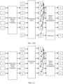
- FIG. 16a and FIG. 16b show an example of a transmitter and an example of a receiver according to embodiments of this application.
- FIG. 16a shows the transmitter.
- Output M of the transmitter is a transmission symbol, and there may be one or more M.
- M in FIG. 16a may include M 1 to M N .
- a waveform may be generated when the transmission symbol passes through a waveform generation module. For example, inverse Fourier transform (inverse fast Fourier transformation, IFFT) is performed on the transmission symbol to generate an OFDM symbol.
- IFFT inverse fast Fourier transformation
- input of the transmitter may be a to-be-encoded bit
- the transmitter may encode the to-be-encoded bit
- output of the transmitter may be an encoded bit stream.
- a device at a transmitting end for example, the network device, may modulate the encoded bit stream to obtain the transmission symbol.
- input of the transmitter may be an encoded bit stream.
- the transmitter may map the encoded bit stream to the transmission symbol, and output of the transmitter may be the transmission symbol.
- a device at a transmitting end for example, the network device, may perform channel coding on a bit stream to be encoded, to obtain the encoded bit stream, and use the encoded bit stream as the input of the transmitter.
- input of the transmitter may be a bit stream to be encoded, the transmitter may perform channel coding on a bit to be encoded and map a transmission symbol, and output of the transmitter may be the transmission symbol.
- input of the transmitter may be a modulation symbol, the transmitter may map from the modulation symbol to a transmission symbol, and output of the transmitter may be the transmission symbol.
- FIG. 16a is an example of the transmitter, and a neural network in the transmitter may obtain modulation symbols Q 1 to Q N .
- the modulation symbols Q 1 to Q N may be used as the input of the input layer.
- the input layer may perform dimension increase processing on the modulation symbols Q 1 to Q N , to obtain high-dimensional modulation symbols h 1 to h N .
- An interaction layer may obtain a feature between the modulation symbols and a feature of each modulation symbol from h' 1 to h' N based on h 1 to h N .
- Input of an output layer is h' 1 to h' N , and the output layer may perform dimension reduction on h' 1 to h' N and obtain an aliased transmission symbol.
- the network device may send the transmission symbol to the terminal device.
- the terminal device receives the transmission symbol. For differentiation, the transmission symbol received by the terminal device is described as a received symbol.
- the terminal device may map the received symbol to an RP, to obtain signal vectors r 1 to r N of the received symbol.
- the terminal device may input the signal vectors r 1 to r N to the receiver.
- FIG. 16b is an example of the receiver.
- An input layer of the receiver may perform dimension increase processing on the signal vectors r 1 to r N , to obtain S 1 to S N .
- Input of an interaction layer is S 1 to S N , and the interaction layer may obtain a feature of each signal vector and features h 1 to h N between signal vectors based on S 1 to S N .
- An output layer may obtain log-likelihood ratios L 1 to L N of each received symbol based on h 1 to h N , for channel decoding.
- input h p of an interaction layer is optional, may be a preset or trainable vector, and is mapped to a transmission symbol in an aliased manner to function as a pilot.
- the input S G of the interaction layer is optional, and may be a preset or trainable vector for obtaining global information of S 1 to S N . Details are not described herein.
- the transmitter may obtain puncturing information.
- the transmitter may puncture output of the output layer based on the puncturing information.
- M 2 and M 3 represent that puncturing is performed. In other words, transmission symbols corresponding to the two pieces of output are not sent. Because M 2 and M 3 are punctured, the receiver cannot receive M 2 and M 3 .
- the receiver may obtain the puncturing information.
- a trainable filling vector is set at a puncturing position, to restore a punctured symbol.
- the filling vector is trainable, and may be trained in a gradient backpropagation manner. For example, the receiver may add the filling vector to the corresponding puncturing position based on the puncturing information.
- the network device may obtain the puncturing information based on a puncture rate (puncture rate, PR).
- PR puncture rate
- the PR indicates a percentage of the punctured symbol.
- Table 2 shows some optional PR configurations.
- Optional PR configurations PR Optional configuration 00 5% 01 10% 10 15% 11 20%
- the network device may reserve the first transmission symbol and the last transmission symbol, and evenly puncture symbols.
- N P represents a quantity of resource patches
- n p represents a quantity of puncturing positions
- ⁇ represents a puncturing interval.
- the network device may puncture, based on the obtained puncturing information, the symbol output by the output layer, for example, x 1 and x 2 shown in FIG. 16a .
- the network device may indicate consecutive puncturing positions based on punctured symbol information (puncture pattern indication, PPI).
- PPI indicates a sequence number of a punctured resource patch
- the PPI may indicate a start position of the sequence number of the punctured resource patch.
- the network device may use a bitmap (bitmap) to indicate a puncturing position for inconsecutive puncturing.
- the transmitter and the receiver may synchronize the puncturing information. In other words, the network device and the terminal device may synchronize the puncturing information.
- the network device may send the puncturing information to the receiver by using signaling.
- the network device may send the puncturing information to the terminal device by using downlink control information (downlink control information, DCI) or radio resource control (radio resource control, RRC) signaling.
- the puncturing information may include at least one of the PR and the PPI. In this way, the terminal device may obtain a quantity of punctures by using the PR, and obtain the puncturing position based on the PPI.
- the transmitter and the receiver may synchronize configuration information of the resource patch.
- the network device and the terminal device may synchronize the configuration information of the resource patch.
- FIG. 10B and FIG. 10C Details are not described herein again.
- parameters of the transmitter and the receiver may be jointly trained.
- a function of joint training is to alias information included in a punctured resource patch to a symbol sent by a resource patch that is not punctured, so that interaction information between a receiving end and the transmitting end is maximized, and a bit error rate is reduced.
- An embodiment of this application provides a manner of blindly detecting a puncturing position.
- the receiver may obtain correct puncturing information through blind detection, so that the puncturing information can be used for filling the puncturing position and performing receiving.
- embodiments shown in FIG. 17a, FIG. 17b, and FIG. 17c may be applied to a scenario in which enhanced mobile broadband (enhanced mobile broadband, eMBB) and ultra-reliable and low latency communication (ultra-reliable and low latency communication, uRLLC) coexist.
- eMBB enhanced mobile broadband
- uRLLC ultra-reliable and low latency communication
- a communication apparatus may puncture a scheduled eMBB resource by using a neural network, map uRLLC data to the punctured resource, and send punctured eMBB and uRLLC data.
- a terminal device may receive punctured data.
- the terminal device may perform puncturing pattern recognition on the punctured data, to determine a puncturing position.
- the puncturing pattern recognition may be implemented by using the neural network.
- the terminal device may map the punctured data to a resource patch to obtain a signal vector of the punctured data.
- the terminal device may input the signal vector of the punctured data into the neural network, and output of the neural network is a puncturing position.
- the neural network may include a structure in Manner 1, Manner 2, or Manner 3.
- the terminal device may map the puncturing position and the punctured data to the resource patch to obtain a signal vector of the puncturing position and the signal vector of the punctured data.
- the terminal device may input the signal vector of the puncturing position and the signal vector of the punctured data to a receiver.
- a neural network of the receiver may complete the operations shown in FIG. 3 .
- output of an output layer may be a log-likelihood ratio or the like.
- an output signal vector may be a log-likelihood ratio of the punctured data.
- a terminal device may receive punctured data.
- the terminal device may perform puncturing pattern recognition on the punctured data, to determine a puncturing position.
- the terminal device may map the puncturing position and the punctured data to the resource patch to obtain a signal vector of the puncturing position and a signal vector of the punctured data.
- the terminal device may input one of the signal vector of the puncturing position and the signal vector of the punctured data to a receiver.
- a neural network of the receiver may complete the operations shown in FIG. 3 .
- output of an output layer may be a log-likelihood ratio.
- the terminal device After the terminal device performs channel decoding by using the log-likelihood ratio, if a CRC check fails, the terminal device returns for an operation of performing puncturing pattern recognition on the punctured data to determine the puncturing position, until the CRC check succeeds or all puncturing positions are traversed.
- a terminal device may receive punctured data.
- the terminal device may perform puncturing pattern recognition on the punctured data, to determine a puncturing position.
- the terminal device may map the puncturing position and the punctured data to the resource patch to obtain a signal vector of the puncturing position and a signal vector of the punctured data.
- the terminal device may input one of the signal vector of the puncturing position and the signal vector of the punctured data to a receiver. If a confidence level is greater than or equal to a set threshold, a generated log-likelihood ratio is for channel decoding.
- the terminal device may return for an operation of performing puncturing pattern recognition on the punctured data to determine the puncturing position, until the confidence level is greater than the threshold or all puncturing positions are traversed. Measurement of the confidence level may be implemented by using a task vector.
- FIG. 18 An embodiment of this application provides a communication apparatus 1800.
- the apparatus 1800 includes a processing unit 1801 and a transceiver unit 1802.
- the apparatus 1800 may be a communication apparatus, or may be an apparatus that is used in a communication apparatus and that can support the communication apparatus in performing a signal processing method.
- the transceiver unit may also be referred to as a transceiver module, a transceiver, a transceiver machine, a transceiver apparatus, or the like.
- the processing unit may also be referred to as a processor, a processing board, a processing unit, a processing apparatus, or the like.
- a component that is in the transceiver unit and that is configured to implement a receiving function may be considered as a receiving unit.
- the transceiver unit is configured to perform a sending operation and a receiving operation of the communication apparatus in the foregoing method embodiments, and a component that is in the transceiver unit and that is configured to implement a sending function is considered as a sending unit. That is, the transceiver unit includes the receiving unit and the sending unit.
- the transceiver unit may be an input/output circuit and/or a communication interface, and perform an input operation (corresponding to the foregoing receiving operation) and an output operation (corresponding to the foregoing sending operation); and the processing unit is an integrated processor, a microprocessor, or an integrated circuit.
- the apparatus 1800 when used in the communication apparatus, operations performed by units of the apparatus 1800 are described in detail.
- the transceiver unit 1802 is configured to obtain an input signal.
- the processing unit 1801 is configured to: map the input signal to N1 resource patches RPs, where the RP includes one or more resource elements REs, and each RP includes one signal vector determined based on the input signal; input N1 signal vectors to an input layer of a neural network for dimension increase processing, to obtain N2 high-dimensional signal vectors; input the N2 high-dimensional signal vectors to an interaction layer of the neural network, to obtain a feature between the N2 high-dimensional signal vectors and a feature of each high-dimensional signal vector; and input the feature between the N2 high-dimensional signal vectors and the feature of each high-dimensional signal vector to an output layer of the neural network for an operation, to obtain an output signal vector.
- an embodiment of this application provides a communication apparatus 1900.
- the communication apparatus 1900 includes a processor 1910.
- the communication apparatus 1900 may further include a memory 1920, configured to store instructions executed by the processor 1910, store input data required by the processor 1910 to run instructions, or store data generated after the processor 1910 runs instructions.
- the processor 1910 may implement, by using the instructions stored in the memory 1920, the method shown in the foregoing method embodiments.
- an embodiment of this application provides a communication apparatus 2000.
- the communication apparatus 2000 may be a chip or a chip system.
- the chip system may include a chip, or may include a chip and another discrete component.
- the communication apparatus 2000 may include at least one processor 2010.
- the processor 2010 is coupled to a memory.
- the memory may be located inside the apparatus, or may be located outside the apparatus.
- the communication apparatus 2000 may further include at least one memory 2020.
- the memory 2020 stores a computer program, configuration information, a computer program or instructions, and/or data necessary for implementing any one of the foregoing embodiments.
- the processor 2010 may execute the computer program stored in the memory 2020, to complete the method in any one of the foregoing embodiments.
- the memory may be integrated with the processor.
- the coupling in this embodiment of this application may be an indirect coupling or a communication connection between apparatuses, units, or modules in an electrical form, a mechanical form, or another form, and is used for information exchange between the apparatuses, the units, or the modules.
- the processor 2010 may cooperate with the memory 2020.
- a specific connection medium among the transceiver 2030, the processor 2010, and the memory 2020 is not limited.
- the communication apparatus 2000 may further include a transceiver 2030, and the communication apparatus 2000 may exchange information with another device by using the transceiver 2030.
- the transceiver 2030 may be a circuit, a bus, a transceiver, or any other apparatus that may be configured to exchange information, or is referred to as a signal transceiver unit. As shown in FIG. 20 , the transceiver 2030 includes a transmitter 2031, a receiver 2032, and an antenna 2033.
- the transceiver in the communication apparatus 2000 may alternatively be an input/output circuit and/or a communication interface, and may input data (or is referred to as receiving data) and output data (or is referred to as sending data).
- the processor is an integrated processor, a microprocessor, or an integrated circuit, and the processor may determine output data based on input data.
- the communication apparatus 2000 may be used in a communication apparatus.
- the communication apparatus 2000 may be a communication apparatus, or may be an apparatus that can support a communication apparatus and implement a function of the communication apparatus in any one of the foregoing embodiments.
- the memory 2020 stores a computer program, a computer program or instructions, and/or data necessary for implementing a function of the communication apparatus in any one of the foregoing embodiments.
- the processor 2010 may execute the computer program stored in the memory 2020, to complete the method performed by the communication apparatus in any one of the foregoing embodiments.
- the communication apparatus 2000 according to this embodiment may be used in the communication apparatus, to complete the method performed by the foregoing communication apparatus. Therefore, for technical effects that can be achieved by this embodiment, refer to the foregoing method embodiments. Details are not described herein again.
- the processor may be a general-purpose processor, a digital signal processor, an application-specific integrated circuit, a field programmable gate array or another programmable logic device, a discrete gate or transistor logic device, or a discrete hardware component, and may implement or perform the methods, steps, and logical block diagrams disclosed in embodiments of this application.
- the general-purpose processor may be a microprocessor or any conventional processor or the like. The steps of the method disclosed with reference to embodiments of this application may be directly performed by a hardware processor, or may be performed by using a combination of hardware in the processor and a software module.
- the memory may be a non-volatile memory, for example, a hard disk drive (hard disk drive, HDD) or a solid-state drive (solid-state drive, SSD), or may be a volatile memory (volatile memory), for example, a random access memory (random access memory, RAM).
- the memory may be any other medium that can be configured to carry or store expected program code in a form of an instruction or a data structure and that can be accessed by a computer, but is not limited thereto.
- the memory in embodiments of this application may alternatively be a circuit or any other apparatus that can implement a storage function, and is configured to store a computer program, a computer program or instructions, and/or data.
- An embodiment of this application further provides another communication apparatus 2100, including an input/output interface 2110 and a logic circuit 2120.
- the input/output interface 2110 is configured to receive code instructions and transmit the code instructions to the logic circuit 2120; and the logic circuit 2120 is configured to run the code instructions to perform the method performed by the communication apparatus in any one of the foregoing embodiments.
- the following describes in detail an operation performed when the communication apparatus is used in a communication apparatus.
- the communication apparatus 2100 may be used in the communication apparatus, to perform the method performed by the communication apparatus, specifically for example, the method performed by the communication apparatus in the embodiment shown in FIG. 3 .
- the input/output interface 2110 is configured to obtain an input signal.
- the logic circuit 2120 is configured to: map the input signal to N1 resource patches RPs, where the RP includes one or more resource elements REs, and each RP includes one signal vector determined based on the signal; input N1 signal vectors to an input layer of a neural network for dimension increase processing, to obtain N2 high-dimensional signal vectors; input the N2 high-dimensional signal vectors to an interaction layer of the neural network, to obtain a feature between the N2 high-dimensional signal vectors and a feature of each high-dimensional signal vector; and input the feature between the N2 high-dimensional signal vectors and the feature of each high-dimensional signal vector to an output layer of the neural network for an operation, to obtain an output signal vector.
- the communication apparatus 2100 according to this embodiment may be used in the communication apparatus, to perform the method performed by the foregoing communication apparatus. Therefore, for technical effects that can be achieved by this embodiment, refer to the foregoing method embodiments. Details are not described herein again.
- an embodiment of this application further provides a communication system.
- the system includes at least one communication apparatus and at least one other communication apparatus.
- an embodiment of this application further provides a computer-readable storage medium.
- the computer-readable storage medium stores a computer program or instructions. When the instructions are executed, the method performed by the communication apparatus in any one of the foregoing embodiments is implemented.
- the computer-readable storage medium may include: any medium that can store program code, such as a USB flash drive, a removable hard disk, a read-only memory, a random access memory, a magnetic disk, or an optical disc.
- an embodiment of this application further provides a chip, including a processor, configured to support the communication apparatus in implementing the functions of the communication apparatus in the foregoing method embodiments.
- the chip is connected to a memory, or the chip includes a memory.
- the memory is configured to store a computer program or instructions and data that are necessary for the communication apparatus.
- this application may be provided as a method, a system, or a computer program product. Therefore, this application may use a form of hardware only embodiments, software only embodiments, or embodiments with a combination of software and hardware. In addition, this application may use a form of a computer program product that is implemented on one or more computer-usable storage media (including but not limited to a disk memory, a CD-ROM, an optical memory, and the like) that include computer-usable program code.
- computer-usable storage media including but not limited to a disk memory, a CD-ROM, an optical memory, and the like
- the computer program or instructions may be provided for a general-purpose computer, a dedicated computer, an embedded processor, or a processor of another programmable data processing device to generate a machine, so that the instructions executed by the computer or the processor of another programmable data processing device generate an apparatus for implementing a specific function in one or more procedures in the flowcharts and/or in one or more blocks in the block diagrams.
- the computer program or instructions may alternatively be stored in a computer-readable memory that can instruct the computer or the another programmable data processing device to work in a specific manner, so that the instructions stored in the computer-readable memory generate an artifact that includes an instruction apparatus.
- the instruction apparatus implements a specified function in one or more procedures in the flowcharts and/or in one or more blocks in the block diagrams.
- the computer program or instructions may alternatively be loaded onto the computer or the another programmable data processing device, so that a series of operation steps are performed on the computer or the another programmable device to generate computer-implemented processing. Therefore, the instructions executed on the computer or the another programmable device provide steps for implementing a specific function in one or more procedures in the flowcharts and/or in one or more blocks in the block diagrams.
Landscapes
- Engineering & Computer Science (AREA)
- Theoretical Computer Science (AREA)
- Physics & Mathematics (AREA)
- Signal Processing (AREA)
- Computer Networks & Wireless Communication (AREA)
- Artificial Intelligence (AREA)
- Evolutionary Computation (AREA)
- Power Engineering (AREA)
- General Health & Medical Sciences (AREA)
- Mathematical Physics (AREA)
- Computational Linguistics (AREA)
- Molecular Biology (AREA)
- Computing Systems (AREA)
- General Engineering & Computer Science (AREA)
- General Physics & Mathematics (AREA)
- Data Mining & Analysis (AREA)
- Software Systems (AREA)
- Biophysics (AREA)
- Biomedical Technology (AREA)
- Life Sciences & Earth Sciences (AREA)
- Health & Medical Sciences (AREA)
- Quality & Reliability (AREA)
- Mobile Radio Communication Systems (AREA)
Applications Claiming Priority (2)
| Application Number | Priority Date | Filing Date | Title |
|---|---|---|---|
| CN202210338001.1A CN116938644A (zh) | 2022-03-31 | 2022-03-31 | 一种信号处理方法和装置 |
| PCT/CN2023/085029 WO2023185999A1 (zh) | 2022-03-31 | 2023-03-30 | 一种信号处理方法和装置 |
Publications (2)
| Publication Number | Publication Date |
|---|---|
| EP4475498A1 true EP4475498A1 (de) | 2024-12-11 |
| EP4475498A4 EP4475498A4 (de) | 2025-06-11 |
Family
ID=88199402
Family Applications (1)
| Application Number | Title | Priority Date | Filing Date |
|---|---|---|---|
| EP23778364.2A Pending EP4475498A4 (de) | 2022-03-31 | 2023-03-30 | Signalverarbeitungsverfahren und -vorrichtung |
Country Status (4)
| Country | Link |
|---|---|
| US (1) | US20250023762A1 (de) |
| EP (1) | EP4475498A4 (de) |
| CN (1) | CN116938644A (de) |
| WO (1) | WO2023185999A1 (de) |
Families Citing this family (1)
| Publication number | Priority date | Publication date | Assignee | Title |
|---|---|---|---|---|
| TWI807905B (zh) * | 2022-07-07 | 2023-07-01 | 創鑫智慧股份有限公司 | 推薦系統中建構特徵交互的全交互方法與裝置 |
Family Cites Families (6)
| Publication number | Priority date | Publication date | Assignee | Title |
|---|---|---|---|---|
| DE50012539D1 (de) * | 1999-05-24 | 2006-05-18 | Ipcentury Ag | Neuronales netz zum computergestützten wissensmanagement |
| US10771493B2 (en) * | 2018-09-18 | 2020-09-08 | International Business Machines Corporation | Cognitive security exposure analysis and resolution based on security trends |
| CN111049615B (zh) * | 2018-10-15 | 2021-01-05 | 华为技术有限公司 | 处理信号的方法和装置 |
| CN110266620B (zh) * | 2019-07-08 | 2020-06-30 | 电子科技大学 | 基于卷积神经网络的3d mimo-ofdm系统信道估计方法 |
| CN116054888B (zh) * | 2020-04-07 | 2026-01-27 | 东莞理工学院 | 一种天线信号的原始信号重构方法及装置 |
| US11631338B2 (en) * | 2020-06-11 | 2023-04-18 | Act, Inc. | Deep knowledge tracing with transformers |
-
2022
- 2022-03-31 CN CN202210338001.1A patent/CN116938644A/zh active Pending
-
2023
- 2023-03-30 WO PCT/CN2023/085029 patent/WO2023185999A1/zh not_active Ceased
- 2023-03-30 EP EP23778364.2A patent/EP4475498A4/de active Pending
-
2024
- 2024-09-30 US US18/902,430 patent/US20250023762A1/en active Pending
Also Published As
| Publication number | Publication date |
|---|---|
| EP4475498A4 (de) | 2025-06-11 |
| CN116938644A (zh) | 2023-10-24 |
| WO2023185999A9 (zh) | 2023-11-09 |
| WO2023185999A1 (zh) | 2023-10-05 |
| US20250023762A1 (en) | 2025-01-16 |
Similar Documents
| Publication | Publication Date | Title |
|---|---|---|
| US20230198699A1 (en) | Reference signal configuration, information transmission, and information receiving methods and device | |
| CN107222244B (zh) | 一种信道信息上报方法、装置及系统 | |
| Gao et al. | Beamspace channel estimation for wideband millimeter-wave MIMO with lens antenna array | |
| CN119814252B (zh) | 一种被用于无线通信的节点中的csi上报的方法和装置 | |
| US20240171429A1 (en) | Communication method and apparatus | |
| US20250088323A1 (en) | Reference signal assignment | |
| US20250023762A1 (en) | Signal processing method and apparatus | |
| WO2023064529A1 (en) | Geometric mean decomposition precoding for wireless communication | |
| CN117728930A (zh) | 数据传输的方法和通信装置 | |
| CN118056429A (zh) | 虚拟信道样本的质量评估方法和设备 | |
| CN114513280A (zh) | 一种极化编码方法和装置 | |
| CN102647218A (zh) | 处理多输入多输出预编码的测地内插的方法及其通讯装置 | |
| KR20180025264A (ko) | 통신 시스템에서 다중 접속을 위한 방법 및 장치 | |
| CN114513212A (zh) | 一种极化编码方法和装置 | |
| US20260095287A1 (en) | Communication method and related apparatus | |
| WO2024250463A1 (en) | Communication method and related apparatus | |
| US20250097736A1 (en) | Transmitting datasets in wireless communication systems | |
| US20250301454A1 (en) | Communication method and communication apparatus | |
| US20250088258A1 (en) | Model application method and apparatus | |
| US20260045998A1 (en) | Method and device for estimating and predicting channel of secondary cell in wireless communication system | |
| WO2024250470A1 (en) | Method and apparatus for reporting channel information | |
| WO2024250472A1 (en) | Method and apparatus for communications | |
| WO2024250467A1 (en) | Method and apparatus for communications | |
| US20260004403A1 (en) | Swin transformer-based wireless channel estimation | |
| WO2024250464A1 (en) | Communication method and related apparatus |
Legal Events
| Date | Code | Title | Description |
|---|---|---|---|
| STAA | Information on the status of an ep patent application or granted ep patent |
Free format text: STATUS: THE INTERNATIONAL PUBLICATION HAS BEEN MADE |
|
| PUAI | Public reference made under article 153(3) epc to a published international application that has entered the european phase |
Free format text: ORIGINAL CODE: 0009012 |
|
| STAA | Information on the status of an ep patent application or granted ep patent |
Free format text: STATUS: REQUEST FOR EXAMINATION WAS MADE |
|
| 17P | Request for examination filed |
Effective date: 20240906 |
|
| AK | Designated contracting states |
Kind code of ref document: A1 Designated state(s): AL AT BE BG CH CY CZ DE DK EE ES FI FR GB GR HR HU IE IS IT LI LT LU LV MC ME MK MT NL NO PL PT RO RS SE SI SK SM TR |
|
| A4 | Supplementary search report drawn up and despatched |
Effective date: 20250513 |
|
| RIC1 | Information provided on ipc code assigned before grant |
Ipc: H04B 7/0413 20170101ALN20250507BHEP Ipc: H04L 1/00 20060101ALN20250507BHEP Ipc: G06N 3/0464 20230101ALN20250507BHEP Ipc: G06N 3/08 20230101ALI20250507BHEP Ipc: G06N 3/045 20230101ALI20250507BHEP Ipc: G06N 3/0499 20230101ALI20250507BHEP Ipc: H04L 25/02 20060101AFI20250507BHEP |
|
| DAV | Request for validation of the european patent (deleted) | ||
| DAX | Request for extension of the european patent (deleted) |