EP4475437A2 - Verfahren und vorrichtung zur kreuzkorrelation - Google Patents
Verfahren und vorrichtung zur kreuzkorrelation Download PDFInfo
- Publication number
- EP4475437A2 EP4475437A2 EP24208112.3A EP24208112A EP4475437A2 EP 4475437 A2 EP4475437 A2 EP 4475437A2 EP 24208112 A EP24208112 A EP 24208112A EP 4475437 A2 EP4475437 A2 EP 4475437A2
- Authority
- EP
- European Patent Office
- Prior art keywords
- spike
- delay
- stream
- function
- accumulated value
- Prior art date
- Legal status (The legal status is an assumption and is not a legal conclusion. Google has not performed a legal analysis and makes no representation as to the accuracy of the status listed.)
- Pending
Links
Images


Classifications
-
- H—ELECTRICITY
- H03—ELECTRONIC CIRCUITRY
- H03K—PULSE TECHNIQUE
- H03K5/00—Manipulating of pulses not covered by one of the other main groups of this subclass
-
- G—PHYSICS
- G06—COMPUTING OR CALCULATING; COUNTING
- G06F—ELECTRIC DIGITAL DATA PROCESSING
- G06F17/00—Digital computing or data processing equipment or methods, specially adapted for specific functions
- G06F17/10—Complex mathematical operations
- G06F17/15—Correlation function computation including computation of convolution operations
-
- G—PHYSICS
- G06—COMPUTING OR CALCULATING; COUNTING
- G06N—COMPUTING ARRANGEMENTS BASED ON SPECIFIC COMPUTATIONAL MODELS
- G06N3/00—Computing arrangements based on biological models
- G06N3/02—Neural networks
- G06N3/04—Architecture, e.g. interconnection topology
- G06N3/049—Temporal neural networks, e.g. delay elements, oscillating neurons or pulsed inputs
-
- G—PHYSICS
- G06—COMPUTING OR CALCULATING; COUNTING
- G06N—COMPUTING ARRANGEMENTS BASED ON SPECIFIC COMPUTATIONAL MODELS
- G06N3/00—Computing arrangements based on biological models
- G06N3/02—Neural networks
- G06N3/06—Physical realisation, i.e. hardware implementation of neural networks, neurons or parts of neurons
- G06N3/063—Physical realisation, i.e. hardware implementation of neural networks, neurons or parts of neurons using electronic means
- G06N3/065—Analogue means
-
- G—PHYSICS
- G06—COMPUTING OR CALCULATING; COUNTING
- G06N—COMPUTING ARRANGEMENTS BASED ON SPECIFIC COMPUTATIONAL MODELS
- G06N3/00—Computing arrangements based on biological models
- G06N3/02—Neural networks
- G06N3/08—Learning methods
-
- G—PHYSICS
- G06—COMPUTING OR CALCULATING; COUNTING
- G06N—COMPUTING ARRANGEMENTS BASED ON SPECIFIC COMPUTATIONAL MODELS
- G06N3/00—Computing arrangements based on biological models
- G06N3/02—Neural networks
- G06N3/08—Learning methods
- G06N3/088—Non-supervised learning, e.g. competitive learning
-
- H—ELECTRICITY
- H03—ELECTRONIC CIRCUITRY
- H03K—PULSE TECHNIQUE
- H03K5/00—Manipulating of pulses not covered by one of the other main groups of this subclass
- H03K5/159—Applications of delay lines not covered by the preceding subgroups
-
- H—ELECTRICITY
- H03—ELECTRONIC CIRCUITRY
- H03K—PULSE TECHNIQUE
- H03K5/00—Manipulating of pulses not covered by one of the other main groups of this subclass
- H03K5/19—Monitoring patterns of pulse trains
-
- H—ELECTRICITY
- H03—ELECTRONIC CIRCUITRY
- H03K—PULSE TECHNIQUE
- H03K5/00—Manipulating of pulses not covered by one of the other main groups of this subclass
- H03K5/22—Circuits having more than one input and one output for comparing pulses or pulse trains with each other according to input signal characteristics, e.g. slope, integral
-
- H—ELECTRICITY
- H03—ELECTRONIC CIRCUITRY
- H03K—PULSE TECHNIQUE
- H03K5/00—Manipulating of pulses not covered by one of the other main groups of this subclass
- H03K2005/00013—Delay, i.e. output pulse is delayed after input pulse and pulse length of output pulse is dependent on pulse length of input pulse
- H03K2005/00019—Variable delay
- H03K2005/00058—Variable delay controlled by a digital setting
-
- H—ELECTRICITY
- H03—ELECTRONIC CIRCUITRY
- H03K—PULSE TECHNIQUE
- H03K5/00—Manipulating of pulses not covered by one of the other main groups of this subclass
- H03K5/22—Circuits having more than one input and one output for comparing pulses or pulse trains with each other according to input signal characteristics, e.g. slope, integral
- H03K5/26—Circuits having more than one input and one output for comparing pulses or pulse trains with each other according to input signal characteristics, e.g. slope, integral the characteristic being duration, interval, position, frequency, or sequence
Definitions
- the present invention relates generally to cross correlation, and, more particularly, to cross correlation of data streams with significant stochastic content.
- Cross correlation is well understood in signal processing, and often used to find the relative delay between signal streams in a variety of applications.
- Established methods of cross correlation compare signal similarity at multiple relative delay offsets, typically seeking the offset of maximum similarity.
- WO 20135/127106 A1 discloses a method of operating a spiking neural network having neurons coupled together with a synapse includes monitoring a timing of a presynaptic spike and monitoring a timing of a postsynaptic spike. The method includes determining a time difference between the postsynaptic spike and the presynaptic spike. The method further includes calculating a stochastic update of a delay for the synapse based on the time difference between the postsynaptic spike and the presynaptic spike.
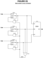
- Figure 1 depicts an example application scenario, in the area of spiking neural networks.
- the inputs on the left are three streams of spikes: S1, S2, and S3.
- Each spike stream is expected to contain significant random (or stochastic) content.
- FOR (that may alternatively be written as “F.O.R.”) means “Frame Of Reference.” (Unless context indicates otherwise, any use herein of the term “FOR” or “F.O.R.” is a reference to a "Frame Of Reference,” and not to the preposition "for.")
- the spike stream presented to a CCU's FOR input appears, after some modification, at the CCU's FOR d output.
- a CCU has the possibility of modifying its FOR d output stream, relative to the spikes appearing at its FOR input, by inserting a delay.
- the "Other” input, for each CCU is intended to be a union of the spikes appearing at the FOR d outputs of the other CCU's (i.e., the other CCU's connected to a same Soma).
- the MCC of the present invention relies upon the presence of large numbers (e.g., hundreds or thousands) of random spikes.
- the MCC operates by having each CCU operate essentially independently of the other CCU's.
- the exception to independent operation is the fact that each CCU receives (at its Other input) the union of the FOR d outputs of the other CCU's (rather than, for example, a union of the spike streams as presented to the FOR inputs of the other CCU's).
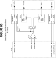
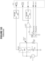
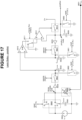
- Figure 2 is a functional block diagram of an example internal structure, for each CCU of Figure 1 .
- a CCU is comprised of two main units:
- Learn Delay accepts the CCU's Other spike stream (from the CCU's Other input 0210), as well as accepting (at Learn Delay's F.O.R. d input) the F.O.R. d output of Produce Delay.
- Learn Delay uses each pair of spikes, present at its F.O.R. d input, as a frame of reference for analyzing any spikes occurring at Learn Delay's Other input.
- Produce Delay incorporates sufficient memory, it can reproduce (at its F.O.R. d output) a spike stream that, except for the possibility of delay, is identical to the spike stream at its F.O.R. input.
- Produce Delay can reproduce (at its F.O.R. d output) a spike stream that, except for the possibility of delay, is identical to the spike stream at its F.O.R. input.
- Produce Delay can be implemented with analog or digital equipment.
- Produce Delay can comprise, for example, a FIFO (First In First Out) queue, or buffer, implemented with semiconductor random access memory (RAM).
- Produce Delay can comprise any suitable signal or wave guide, such as an electrical cable or a free-space wave propagation cavity.
- Another important aspect of the present invention is utilizing the stochastic nature of the spike stream, presented to a CCU's F.O.R. input, to produce a lossy version of F.O.R. d at Produce Delay's output.
- a memory of only one spike (at a time), by Produce Delay can be sufficient to produce a useful correlated spike stream at a CCU's F.O.R. d output.
- Produce Delay can be viewed as a kind of "timer.” When a spike appears at its F.O.R. input, the timer can be started. At the conclusion of the delay period, the timer produces a spike for Produce Delay's F.O.R. d output.
- Use of a single spike memory is discussed below, in Section 2.3 ("Produce Delay").
- Learn Delay uses each pair of spikes, present at its F.O.R. d input, as a frame of reference for analyzing any spikes occurring at Learn Delay's Other input.
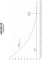
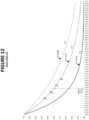
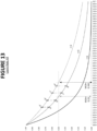
- Figure 3 depicts an example situation of this kind.
- Figure 3 contains two axes:
- the weight axis is relevant to curves 0320 and 0321.
- 0320 is an exponential decay curve, of the form e -rt , where r is rate, t is time, and r (for purposes of example) equals 3.
- 0321 is an exponential increase curve, of the form e -r(m-t) , where r and t are the same as for 0320, and m (for "max" time) equals 0.60 sec.
- curves 0320 and 0321 are also referred to as, respectively, "Post” and "Pre.”
- Each Other spike, that occurs between F.O.R. d spikes n and n+1, is assigned both a Post and Pre value.
- An Other spike, where its Post value is greater than its Pre value is characterized as being more strongly "post” (or after) spike n than "pre” (or before) spike n+1.
- a spike where its Pre value is greater than its Post value is characterized as being more strongly “pre” (or before) spike n+1 than “post” (or after) spike n.
- FIG. 3 depicts two example Other spikes with the following values:
- each Other spike is given two weights, depending upon where it intersects the Post and Pre weighting curves.
- the incremental amount by which the delay of Learn Delay changes can be selected based upon the particular application, and its requirement of speed versus accuracy.
- a smaller increment also called a slower learning rate
- a smaller increment has the advantage of resulting in a more accurate determination of the necessary delay value.
- a CCU (and the MCC of which it is a part) is expected to operate on a spike-by-spike basis. For example, upon each spike present at Learn Delay's F.O.R. d input, that we can refer to as a spike n, Learn Delay can be expected to perform two main operations:
- Learn Delay As a computer program, as electrical hardware, or as a hybrid combination of the two approaches.
- Figure 4 depicts an example pseudo-coded implementation of Learn Delay, based on the Python programming language.
- Bold-faced text corresponds closely to Python syntax and semantics. Comments are inserted according to Python syntax. Line numbers have been added on the left, to aid explanation. A main departure from Python syntax and semantics is the right hand side of the assignment operators, on lines 5-17. Also, the passing of parameters or other data, into and out of the procedure, is handled informally.
- Learn_Delay_PC is invoked each time a spike occurs, at either the F.O.R. d or Other inputs.
- Line 22 updates the Pre accumulator "preAcc,” by causing its contents to undergo exponential decay, relative to the amount of time (i.e., T - TLO) since a last Other spike caused an invocation of Learn_Delay_PC (where T and TLO are defined at lines 8-9 of Figure 4 ).
- T and TLO are defined at lines 8-9 of Figure 4 .
- this exponential decay of preAcc is coupled with adding a unit value to preAcc, at each time an Other spike occurs.
- Adding a unit value to preAcc at the time of each Other spike, and causing the preAcc to undergo exponential decay (until the time of the next F.O.R. d spike), is mathematically equivalent to the preAcc accumulation method discussed above with respect to Figure 3 : adding the value of e -r(m-t) to the preAcc upon the occurrence of each Other spike (where m is the maximum value for t), and having a preAcc that does not decay.
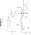
- Each spike at the start/restart input triggers one shot 1020.
- One shot 1020 generates a pulse that, while asserted, prepares capacitor 1040 to produce a new period of exponential decay by switches S1 and S2 of switching unit 1043. Specifically, for the duration of the one shot's pulse:
- both the Produce Delay and Learn Delay functional blocks (e.g., blocks 0220 and 0226 of Figure 8 ) work through the use exponential decay curves.
- the rate of decay r, for these functions, can be selected based upon the expected spike frequencies of the particular application.
- r ALL is a good value to use as r, for the decay functions of Produce Delay and Learn Delay.
- r ALL can be used for the Post and Pre functions. Using this value for r tends to ensure the Other spikes are located on regions where each function is changing relatively rapidly, and is therefore easier to measure. A similar advantage is achieved by using r ALL for the decay rate (e.g., see function 0910 of Figure 9 ) by which Produce Delay measures delay.
- r ALL will be determined, with ⁇ r selected to provide a suitable tradeoff, between speed of convergence to r ALL (also called the "learning rate") and accuracy of the r ALL value determined:
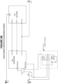
- Outline 1610 of Figure 16 indicates the external interface for LRA, where each connection corresponds to an input or output of LRA functional block 0223 of Figure 11 .
- Equation 1 The exponential decay of Equation 1 is performed, in Figure 16 , by the combination of capacitor 1630 and variable resistor 1631. The decay value is available at "decay" node 1641. Equation 3 (exponential increase) is performed by subtractive amplifier 1621 as follows:
- Equation 1 Equality testing, between Equation 1 and Equation 3, is performed by comparator amplifier 1622, with the result (corresponding to the MEA guess of the above explanation) available at node 1642.
- comparator 1622 can be interpreted as follows:
- the logical 1 on node 1642 causes AND gate 1623 to be enabled, and the out1 pulse is applied to the R- input of variable resistor 1631.
- decreasing resistance causes a faster rate of decay at "decay" node 1641, and a downward adjustment to MEA guess .
- variable resistor 1631 determines the increment of change to r guess , where the magnitude of each such increment of change is referred to as the ⁇ r "learning rate" in the above discussion.
- LRA 0223 can provide its r ALL output to the r ALL input of each of Produce Delay 0227 and Learn Delay 0228.
- Figure 10 is replaced by Figure 19.
- Figure 19 differs from Figure 10 as follows: fixed resistor 1041 ( Figure 10 ) is replaced with variable resistor 1044 ( Figure 19 ) that accepts an r ALL input as part of its external interface 1011.
- Suitable hardware can include the use of one or more general purpose computers or processors.
- Hardware implementation techniques can include the use of various types of integrated circuits, programmable memories (volatile and nonvolatile), or both.
- Computational hardware is typically based upon the use of transistors (field effect, bipolar, or both), although other types of components (e.g., optical, microelectromechanical, or magnetic) may be included. Any computational hardware has the property that it will consume energy, as a necessary part of being able to perform its function. Also, regardless of how quickly it can be made to operate, computational hardware will require some amount of time to change state. Because of its basis on physical devices (electronic or otherwise), computational hardware, however small, will occupy some amount of physical space.
- Programmable memories are also often implemented in integrated circuit form, and are subject to the same physical limitations described above for computational hardware.
- a programmable memory is intended to include devices that use any kind of physics-based effects or properties, in order to store information in at least a non-transitory way, and for an amount of time commensurate with the application.
- the types of physical effects used to implement such storage include, but are not limited to: maintenance of a particular state through a feedback signal, charge storage, changes to optical properties of a material, magnetic changes, or chemical changes (reversible or irreversible).
- a computer program product can be embodied on any suitable computer-readable medium or programmable memory.
- a computer-readable code device can represent that portion of a memory in which a defined unit of information (such as a bit) can be stored, from which a defined unit of information can be retrieved, or both.
- the disclosure relates to a method for cross correlation, comprising: receiving, performed at least in part with a configuration of electronic hardware, a first spike stream containing significant stochastic content, and a first event; receiving, performed at least in part with a configuration of electronic hardware, a second spike stream containing significant stochastic content, and a second event, wherein the first and second events have a fixed temporal relationship; inputting, performed at least in part with a configuration of electronic hardware, the first spike stream into a first delay unit; outputting, performed at least in part with a configuration of electronic hardware, a first delayed spike stream from the first delay unit, wherein a first delay, produced by the first delay unit, has a lower bound of zero seconds; comparing, upon receipt of a first delayed spike from the first delayed spike stream, performed at least in part with a configuration of electronic hardware, a first accumulated value with a second accumulated value to produce a first comparison result; increasing the first delay if the first comparison result indicates the first accumulated value is greater than the second accumulated
- the method comprises: increasing the first delay by increasing the length of a first queue, comprising the first delay unit; and decreasing the first delay by decreasing the length of a first queue.
- the method comprises: timing a duration equal to the first delay, upon an input to the first delay unit of a first undelayed spike from the first spike stream, if a timing by the first delay unit is not already started; outputting a spike, upon a completion of any timing of the first delay; deciding, based upon a first state for a first decision variable, and receipt of a second undelayed spike during a time duration for a prior undelayed spike, to continue with the time duration for the prior undelayed spike; deciding, based upon a second state for the first decision variable, and receipt of the second undelayed spike during the time duration for the prior undelayed spike, to restart a timing of the first delay by the first delay unit; ensuring over multiple instances, of receipt of the second undelayed spike during the time duration for the prior undelayed spike, approximately equal occurrences, for the first decision variable, of the first and second states.
- the method comprises: increasing a first average spike rate, for generating both a first exponential decrease function and a first exponential increase function, if, at a time of receipt of a first undelayed spike from the first spike stream, the first exponential decrease function is greater than the first exponential increase function; decreasing a first average spike rate, for generating both a first exponential decrease function and a first exponential increase function, if, at the time of receipt of the first undelayed spike from the first spike stream, the first exponential decrease function is less than the first exponential increase function; and using the first average spike rate for producing the first and second weighting functions.
- the method comprises: increasing a first average spike rate, for generating both a first exponential decrease function and a first exponential increase function, if, at a time of receipt of a first undelayed spike from the first spike stream, the first exponential decrease function is greater than the first exponential increase function; decreasing a first average spike rate, for generating both a first exponential decrease function and a first exponential increase function, if, at the time of receipt of the first undelayed spike from the first spike stream, the first exponential decrease function is less than the first exponential increase function; and using the first average spike rate for timing the first delay.
- the disclosure relates to a system for cross correlation, comprising: a first subsystem that receives, at least in part with a configuration of electronic hardware, a first spike stream containing significant stochastic content, and a first event; a second subsystem that receives, at least in part with a configuration of electronic hardware, a second spike stream containing significant stochastic content, and a second event, wherein the first and second events have a fixed temporal relationship; a first delay unit that receives, at least in part with a configuration of electronic hardware, the first spike stream, and outputs a first delayed spike stream, wherein a first delay, produced by the first delay unit, has a lower bound of zero seconds; a third subsystem that compares, at least in part with a configuration of electronic hardware, upon receipt of a first delayed spike from the first delayed spike stream, a first accumulated value with a second accumulated value to produce a first comparison result; a fourth subsystem that increases the first delay, at least in part with a configuration of electronic hardware, if
Landscapes
- Engineering & Computer Science (AREA)
- Physics & Mathematics (AREA)
- Theoretical Computer Science (AREA)
- General Physics & Mathematics (AREA)
- Data Mining & Analysis (AREA)
- Mathematical Physics (AREA)
- Computing Systems (AREA)
- Software Systems (AREA)
- General Engineering & Computer Science (AREA)
- Life Sciences & Earth Sciences (AREA)
- Biomedical Technology (AREA)
- Biophysics (AREA)
- Health & Medical Sciences (AREA)
- Artificial Intelligence (AREA)
- General Health & Medical Sciences (AREA)
- Evolutionary Computation (AREA)
- Computational Linguistics (AREA)
- Molecular Biology (AREA)
- Nonlinear Science (AREA)
- Computational Mathematics (AREA)
- Mathematical Analysis (AREA)
- Mathematical Optimization (AREA)
- Pure & Applied Mathematics (AREA)
- Algebra (AREA)
- Databases & Information Systems (AREA)
- Neurology (AREA)
- Synchronisation In Digital Transmission Systems (AREA)
- Measurement Of The Respiration, Hearing Ability, Form, And Blood Characteristics Of Living Organisms (AREA)
- Complex Calculations (AREA)
- Manipulation Of Pulses (AREA)
- Image Analysis (AREA)
Applications Claiming Priority (3)
| Application Number | Priority Date | Filing Date | Title |
|---|---|---|---|
| US201962819590P | 2019-03-17 | 2019-03-17 | |
| EP20773691.9A EP3942695B1 (de) | 2019-03-17 | 2020-03-15 | Verfahren und vorrichtung zur kreuzkorrelation |
| PCT/US2020/022869 WO2020190825A1 (en) | 2019-03-17 | 2020-03-15 | Method and apparatus for cross correlation |
Related Parent Applications (2)
| Application Number | Title | Priority Date | Filing Date |
|---|---|---|---|
| EP20773691.9A Division EP3942695B1 (de) | 2019-03-17 | 2020-03-15 | Verfahren und vorrichtung zur kreuzkorrelation |
| EP20773691.9A Division-Into EP3942695B1 (de) | 2019-03-17 | 2020-03-15 | Verfahren und vorrichtung zur kreuzkorrelation |
Publications (2)
| Publication Number | Publication Date |
|---|---|
| EP4475437A2 true EP4475437A2 (de) | 2024-12-11 |
| EP4475437A3 EP4475437A3 (de) | 2025-02-26 |
Family
ID=72521222
Family Applications (2)
| Application Number | Title | Priority Date | Filing Date |
|---|---|---|---|
| EP20773691.9A Active EP3942695B1 (de) | 2019-03-17 | 2020-03-15 | Verfahren und vorrichtung zur kreuzkorrelation |
| EP24208112.3A Pending EP4475437A3 (de) | 2019-03-17 | 2020-03-15 | Verfahren und vorrichtung zur kreuzkorrelation |
Family Applications Before (1)
| Application Number | Title | Priority Date | Filing Date |
|---|---|---|---|
| EP20773691.9A Active EP3942695B1 (de) | 2019-03-17 | 2020-03-15 | Verfahren und vorrichtung zur kreuzkorrelation |
Country Status (6)
| Country | Link |
|---|---|
| US (2) | US10972082B2 (de) |
| EP (2) | EP3942695B1 (de) |
| JP (1) | JP7389812B2 (de) |
| KR (1) | KR102803834B1 (de) |
| CN (1) | CN113875156B (de) |
| WO (1) | WO2020190825A1 (de) |
Families Citing this family (2)
| Publication number | Priority date | Publication date | Assignee | Title |
|---|---|---|---|---|
| US8473140B2 (en) | 2005-10-21 | 2013-06-25 | Deere & Company | Networked multi-role robotic vehicle |
| WO2020247309A1 (en) * | 2019-06-02 | 2020-12-10 | Barton David Carl | Method and apparatus for shared cross-stream event detection |
Citations (1)
| Publication number | Priority date | Publication date | Assignee | Title |
|---|---|---|---|---|
| WO2013127106A1 (zh) | 2012-02-28 | 2013-09-06 | Wu Donghua | 内置遥控式车锁 |
Family Cites Families (16)
| Publication number | Priority date | Publication date | Assignee | Title |
|---|---|---|---|---|
| JP3469511B2 (ja) * | 1999-08-09 | 2003-11-25 | 日本電信電話株式会社 | 光パルスタイミング検出回路及び光時分割多重装置 |
| WO2004005954A2 (en) * | 2002-07-10 | 2004-01-15 | Qualcomm, Incorporated | Cross-correlation mitigation method and apparatus for use in a global positioning system receiver |
| US7430546B1 (en) | 2003-06-07 | 2008-09-30 | Roland Erwin Suri | Applications of an algorithm that mimics cortical processing |
| CA2642041C (en) * | 2005-12-23 | 2014-07-15 | Le Tan Thanh Tai | Spatio-temporal pattern recognition using a spiking neural network and processing thereof on a portable and/or distributed computer |
| US9460387B2 (en) | 2011-09-21 | 2016-10-04 | Qualcomm Technologies Inc. | Apparatus and methods for implementing event-based updates in neuron networks |
| US8909576B2 (en) | 2011-09-16 | 2014-12-09 | International Business Machines Corporation | Neuromorphic event-driven neural computing architecture in a scalable neural network |
| US9092735B2 (en) * | 2011-09-21 | 2015-07-28 | Qualcomm Incorporated | Method and apparatus for structural delay plasticity in spiking neural networks |
| US9424513B2 (en) * | 2011-11-09 | 2016-08-23 | Qualcomm Incorporated | Methods and apparatus for neural component memory transfer of a referenced pattern by including neurons to output a pattern substantially the same as the referenced pattern |
| US10019470B2 (en) | 2013-10-16 | 2018-07-10 | University Of Tennessee Research Foundation | Method and apparatus for constructing, using and reusing components and structures of an artifical neural network |
| US9342782B2 (en) * | 2014-02-21 | 2016-05-17 | Qualcomm Incorporated | Stochastic delay plasticity |
| US9652711B2 (en) | 2014-03-12 | 2017-05-16 | Qualcomm Incorporated | Analog signal reconstruction and recognition via sub-threshold modulation |
| US9858304B2 (en) * | 2014-04-15 | 2018-01-02 | Raytheon Company | Computing cross-correlations for sparse data |
| EP3043569A1 (de) * | 2015-01-08 | 2016-07-13 | Koninklijke KPN N.V. | Temporäre Beziehungen von Medienströmen |
| GB2544575B (en) * | 2016-06-27 | 2019-10-09 | Sensyne Health Group Ltd | Method and apparatus for sensing and for improving sensor accuracy |
| US10671912B2 (en) * | 2016-09-13 | 2020-06-02 | Sap Se | Spatio-temporal spiking neural networks in neuromorphic hardware systems |
| US10824937B2 (en) * | 2016-12-20 | 2020-11-03 | Intel Corporation | Scalable neuromorphic core with shared synaptic memory and variable precision synaptic memory |
-
2020
- 2020-03-15 JP JP2021551866A patent/JP7389812B2/ja active Active
- 2020-03-15 EP EP20773691.9A patent/EP3942695B1/de active Active
- 2020-03-15 EP EP24208112.3A patent/EP4475437A3/de active Pending
- 2020-03-15 CN CN202080018953.4A patent/CN113875156B/zh active Active
- 2020-03-15 WO PCT/US2020/022869 patent/WO2020190825A1/en not_active Ceased
- 2020-03-15 KR KR1020217033166A patent/KR102803834B1/ko active Active
- 2020-11-16 US US17/099,755 patent/US10972082B2/en active Active
-
2021
- 2021-09-16 US US17/477,514 patent/US20220004845A1/en active Pending
Patent Citations (1)
| Publication number | Priority date | Publication date | Assignee | Title |
|---|---|---|---|---|
| WO2013127106A1 (zh) | 2012-02-28 | 2013-09-06 | Wu Donghua | 内置遥控式车锁 |
Also Published As
| Publication number | Publication date |
|---|---|
| CN113875156B (zh) | 2025-09-09 |
| US20210075409A1 (en) | 2021-03-11 |
| JP7389812B2 (ja) | 2023-11-30 |
| US10972082B2 (en) | 2021-04-06 |
| JP2022524967A (ja) | 2022-05-11 |
| EP3942695C0 (de) | 2025-04-30 |
| CN113875156A (zh) | 2021-12-31 |
| EP4475437A3 (de) | 2025-02-26 |
| KR102803834B1 (ko) | 2025-05-08 |
| EP3942695A1 (de) | 2022-01-26 |
| EP3942695B1 (de) | 2025-04-30 |
| WO2020190825A1 (en) | 2020-09-24 |
| KR20210137191A (ko) | 2021-11-17 |
| EP3942695A4 (de) | 2023-01-18 |
| US20220004845A1 (en) | 2022-01-06 |
Similar Documents
| Publication | Publication Date | Title |
|---|---|---|
| Townsend et al. | Methods of modeling capacity in simple processing systems | |
| US11922281B2 (en) | Training machine learning models using teacher annealing | |
| US10972082B2 (en) | Method and apparatus for cross correlation | |
| CN109145299A (zh) | 一种文本相似度确定方法、装置、设备及存储介质 | |
| CN112069294A (zh) | 一种数学题处理方法、装置、设备及存储介质 | |
| Bernardin et al. | Spiking and collapsing in large noise limits of sdes | |
| CN112995650B (zh) | 用于检测摄像头的视频连续性的方法和装置 | |
| CN115269830B (zh) | 异常文本检测模型训练方法、异常文本检测方法及装置 | |
| Shankar et al. | Optimally fuzzy scale-free memory | |
| US12014261B2 (en) | Method and apparatus for shared cross-stream event detection | |
| CN111275921A (zh) | 一种行为监控方法及装置、电子设备 | |
| CN116909411A (zh) | 一种键盘去抖方法、装置、设备及介质 | |
| CN117752477B (zh) | 一种仿生手的手势锁定控制方法、装置、终端及介质 | |
| CN115904986A (zh) | 特征稳定度检测方法、模型更新方法、设备和存储介质 | |
| Gherasa | How Noisy Is Too Noisy? | |
| Liu et al. | Human-Inspired Audio-Visual Speech Recognition: Spike Activity, Cueing Interaction and Causal Processing | |
| Rozada et al. | Graph-Aware Diffusion for Signal Generation | |
| CN119185946A (zh) | 一种游戏角色行为控制方法、装置、存储介质及电子设备 | |
| CN117540189A (zh) | 差分信号损耗评估高速通道信号的方法 | |
| CN119293162A (zh) | 模型训练方法、信息处理方法、装置、电子设备、存储介质及计算机程序产品 | |
| CN118819279A (zh) | 资源调度方法、装置、电子设备及可读存储介质 | |
| CN118170416A (zh) | 应用投产的数据处理方法、装置和服务器 | |
| CN110968502A (zh) | 基于mfac算法进行遍历测试的系统及方法 | |
| CN111476265A (zh) | 一种感应门控制方法、装置、终端及计算机可读介质 | |
| Wang et al. | Learning recognition of temporal sequences by coding temporal distance in neural networks |
Legal Events
| Date | Code | Title | Description |
|---|---|---|---|
| PUAI | Public reference made under article 153(3) epc to a published international application that has entered the european phase |
Free format text: ORIGINAL CODE: 0009012 |
|
| STAA | Information on the status of an ep patent application or granted ep patent |
Free format text: STATUS: THE APPLICATION HAS BEEN PUBLISHED |
|
| AC | Divisional application: reference to earlier application |
Ref document number: 3942695 Country of ref document: EP Kind code of ref document: P |
|
| AK | Designated contracting states |
Kind code of ref document: A2 Designated state(s): AL AT BE BG CH CY CZ DE DK EE ES FI FR GB GR HR HU IE IS IT LI LT LU LV MC MK MT NL NO PL PT RO RS SE SI SK SM TR |
|
| REG | Reference to a national code |
Ref country code: DE Ref legal event code: R079 Free format text: PREVIOUS MAIN CLASS: H03K0005220000 Ipc: G06N0003040000 |
|
| PUAL | Search report despatched |
Free format text: ORIGINAL CODE: 0009013 |
|
| AK | Designated contracting states |
Kind code of ref document: A3 Designated state(s): AL AT BE BG CH CY CZ DE DK EE ES FI FR GB GR HR HU IE IS IT LI LT LU LV MC MK MT NL NO PL PT RO RS SE SI SK SM TR |
|
| RIC1 | Information provided on ipc code assigned before grant |
Ipc: G06N 3/049 20230101ALI20250122BHEP Ipc: G06N 3/065 20230101ALI20250122BHEP Ipc: G06N 3/088 20230101ALI20250122BHEP Ipc: H03K 5/26 20060101ALI20250122BHEP Ipc: H03K 5/19 20060101ALI20250122BHEP Ipc: H03K 5/15 20060101ALI20250122BHEP Ipc: G06F 17/15 20060101ALI20250122BHEP Ipc: H03K 5/22 20060101ALI20250122BHEP Ipc: H03K 5/159 20060101ALI20250122BHEP Ipc: G06N 3/063 20230101ALI20250122BHEP Ipc: G06N 3/08 20230101ALI20250122BHEP Ipc: G06N 3/02 20060101ALI20250122BHEP Ipc: G06N 3/06 20060101ALI20250122BHEP Ipc: G06N 3/04 20230101AFI20250122BHEP |
|
| STAA | Information on the status of an ep patent application or granted ep patent |
Free format text: STATUS: REQUEST FOR EXAMINATION WAS MADE |
|
| 17P | Request for examination filed |
Effective date: 20250623 |