EP4475402A1 - Axial gap-type motor and air conditioner - Google Patents
Axial gap-type motor and air conditioner Download PDFInfo
- Publication number
- EP4475402A1 EP4475402A1 EP23779206.4A EP23779206A EP4475402A1 EP 4475402 A1 EP4475402 A1 EP 4475402A1 EP 23779206 A EP23779206 A EP 23779206A EP 4475402 A1 EP4475402 A1 EP 4475402A1
- Authority
- EP
- European Patent Office
- Prior art keywords
- stator
- coils
- axial gap
- type motor
- connection plate
- Prior art date
- Legal status (The legal status is an assumption and is not a legal conclusion. Google has not performed a legal analysis and makes no representation as to the accuracy of the status listed.)
- Pending
Links
Images













Classifications
-
- H—ELECTRICITY
- H02—GENERATION; CONVERSION OR DISTRIBUTION OF ELECTRIC POWER
- H02K—DYNAMO-ELECTRIC MACHINES
- H02K21/00—Synchronous motors having permanent magnets; Synchronous generators having permanent magnets
- H02K21/12—Synchronous motors having permanent magnets; Synchronous generators having permanent magnets with stationary armatures and rotating magnets
- H02K21/24—Synchronous motors having permanent magnets; Synchronous generators having permanent magnets with stationary armatures and rotating magnets with magnets axially facing the armatures, e.g. hub-type cycle dynamos
-
- H—ELECTRICITY
- H02—GENERATION; CONVERSION OR DISTRIBUTION OF ELECTRIC POWER
- H02K—DYNAMO-ELECTRIC MACHINES
- H02K1/00—Details of the magnetic circuit
- H02K1/06—Details of the magnetic circuit characterised by the shape, form or construction
- H02K1/12—Stationary parts of the magnetic circuit
- H02K1/18—Means for mounting or fastening magnetic stationary parts on to, or to, the stator structures
- H02K1/182—Means for mounting or fastening magnetic stationary parts on to, or to, the stator structures to stators axially facing the rotor, i.e. with axial or conical air gap
-
- H—ELECTRICITY
- H02—GENERATION; CONVERSION OR DISTRIBUTION OF ELECTRIC POWER
- H02K—DYNAMO-ELECTRIC MACHINES
- H02K3/00—Details of windings
- H02K3/04—Windings characterised by the conductor shape, form or construction, e.g. with bar conductors
- H02K3/28—Layout of windings or of connections between windings
-
- H—ELECTRICITY
- H02—GENERATION; CONVERSION OR DISTRIBUTION OF ELECTRIC POWER
- H02K—DYNAMO-ELECTRIC MACHINES
- H02K3/00—Details of windings
- H02K3/32—Windings characterised by the shape, form or construction of the insulation
- H02K3/34—Windings characterised by the shape, form or construction of the insulation between conductors or between conductor and core, e.g. slot insulation
- H02K3/345—Windings characterised by the shape, form or construction of the insulation between conductors or between conductor and core, e.g. slot insulation between conductor and core, e.g. slot insulation
-
- H—ELECTRICITY
- H02—GENERATION; CONVERSION OR DISTRIBUTION OF ELECTRIC POWER
- H02K—DYNAMO-ELECTRIC MACHINES
- H02K3/00—Details of windings
- H02K3/46—Fastening of windings on the stator or rotor structure
- H02K3/52—Fastening salient pole windings or connections thereto
- H02K3/521—Fastening salient pole windings or connections thereto applicable to stators only
- H02K3/522—Fastening salient pole windings or connections thereto applicable to stators only for generally annular cores with salient poles
-
- H—ELECTRICITY
- H02—GENERATION; CONVERSION OR DISTRIBUTION OF ELECTRIC POWER
- H02K—DYNAMO-ELECTRIC MACHINES
- H02K3/00—Details of windings
- H02K3/46—Fastening of windings on the stator or rotor structure
- H02K3/52—Fastening salient pole windings or connections thereto
- H02K3/521—Fastening salient pole windings or connections thereto applicable to stators only
- H02K3/525—Annular coils, e.g. for cores of the claw-pole type
-
- H—ELECTRICITY
- H02—GENERATION; CONVERSION OR DISTRIBUTION OF ELECTRIC POWER
- H02K—DYNAMO-ELECTRIC MACHINES
- H02K7/00—Arrangements for handling mechanical energy structurally associated with dynamo-electric machines, e.g. structural association with mechanical driving motors or auxiliary dynamo-electric machines
- H02K7/14—Structural association with mechanical loads, e.g. with hand-held machine tools or fans
-
- H—ELECTRICITY
- H02—GENERATION; CONVERSION OR DISTRIBUTION OF ELECTRIC POWER
- H02K—DYNAMO-ELECTRIC MACHINES
- H02K2203/00—Specific aspects not provided for in the other groups of this subclass relating to the windings
- H02K2203/06—Machines characterised by the wiring leads, i.e. conducting wires for connecting the winding terminations
-
- H—ELECTRICITY
- H02—GENERATION; CONVERSION OR DISTRIBUTION OF ELECTRIC POWER
- H02K—DYNAMO-ELECTRIC MACHINES
- H02K2203/00—Specific aspects not provided for in the other groups of this subclass relating to the windings
- H02K2203/09—Machines characterised by wiring elements other than wires, e.g. bus rings, for connecting the winding terminations
Definitions
- the present disclosure relates to an axial gap-type motor and an air conditioner.
- Patent Literature 1 JP 2013-118750 A
- an input-side end to which the power source line is connected is provided on an outer side of a stator in a radial direction, which restricts an outer diameter of a stator core and leads to deterioration in motor magnetic characteristics.
- a restriction on an outer diameter of a stator core hinders higher output and higher efficiency.
- the present disclosure proposes an axial gap-type motor capable of achieving higher output and higher efficiency, and an air conditioner including the axial gap-type motor.
- An axial gap-type motor includes:
- a magnet outer diameter of the rotor can be made larger than a case where the outgoing lines extending from the coils are electrically connected to the power source lines on the outer sides in the radial direction of the stator cores, so that it is possible to achieve higher output and higher efficiency.
- an axial gap-type motor is based on the axial gap motor according to the first aspect and further includes a connection plate in which connecting lines are routed, each of the connecting lines electrically connecting between the outgoing lines of the coils.
- an axial gap-type motor (M) is based on the axial gap motor according to the second aspect, in which the connection plate includes press-fitting portions into which are press-fitted, the outgoing lines of the coils electrically connecting to the connecting lines via the electric connecting terminals.
- an axial gap-type motor according to a fourth aspect of the present disclosure is based on the axial gap-type motor according to the third aspect, in which the stator includes insulators that insulate the stator cores from the coils,
- each of the press-fitting portions at a position along the outgoing direction of the outgoing line drawn out from the outer periphery of the corresponding coil (direction of the tangent to the outer periphery of the coil), connection between the outgoing line and each of the connecting lines at the press-fitting portion in a smooth manner.
- an axial gap-type motor according to a sixth aspect of the present disclosure is based on the axial gap-type motor according to any one of the second aspect to the fifth aspect, in which a cylindrical portion extending in the axial direction of the rotor is provided in a center portion of the connection plate.
- an axial gap-type motor according to a seventh aspect of the present disclosure is based on the axial gap-type motor according to the sixth aspect, in which protrusions that position the connecting lines are provided on an outer peripheral surface of the cylindrical portion of the connection plate.
- an axial gap-type motor according to an eighth aspect of the present disclosure is based on the axial gap-type motor according to any one of the second aspect to the seventh aspect, in which holding portions that hold ends of the connecting lines are provided in an outer peripheral portion of the connection plate.
- the ends of the connecting lines are held, so that it is possible to position, in a reliable manner, the connecting lines in the connection plate.
- an axial gap-type motor according to a ninth aspect of the present disclosure is based on the axial gap-type motor according to any one of the second aspect to the eighth aspect, in which the connection plate is configured to enable routing of the connecting lines to adapt to both series connection of the coils and parallel connection of the coils.
- an axial gap-type motor is based on the axial gap-type motor according to any one of the first aspect to the ninth aspect, in which any one of a U-phase voltage, a V-phase voltage, or a W-phase voltage is applied to the coils via a corresponding one of the power source lines,
- an axial gap-type motor according to an eleventh aspect of the present disclosure is based on the axial gap-type motor according to the first aspect, in which the stator includes insulators that insulate the stator cores from the coils,
- the magnet outer diameter of the rotor can be made larger than a case where the outgoing lines extending from the coils are electrically connected to the power source lines on the outer sides in the radial direction of the stator cores, so that it is possible to achieve higher output and higher efficiency.
- an axial gap-type motor according to a twelfth aspect of the present disclosure is based on the axial gap-type motor according to the eleventh aspect and further includes a connection plate in which connecting lines are routed, each of the connecting lines electrically connecting between the outgoing lines drawn out from the coils.
- an air conditioner according to a thirteenth aspect of the present disclosure includes:
- an axial gap-type motor according to a fourteenth aspect of the present disclosure is based on the axial gap-type motor according to the eleventh aspect or the twelfth aspect and includes a part of the configuration according to the second aspect to the tenth aspect.
- the axial gap-type motor according to the fourteenth aspect of the present disclosure corresponds to an axial gap-type motor obtained by applying the part of the configuration according to the second aspect to the tenth aspect to the axial gap-type motor according to the eleventh aspect or the twelfth aspect.
- an air conditioner according to a fifteenth aspect of the present disclosure includes:
- An axial gap-type motor includes:
- an axial gap-type motor includes a connection plate in which connecting lines that electrically connect between the outgoing lines drawn out from the coils are routed.
- an air conditioner according to an eighteenth aspect of the present disclosure includes:
- Fig. 1 is an overall perspective view of an axial gap-type motor M of a first embodiment of the present disclosure
- Fig. 2 is an exploded perspective view of the axial gap-type motor M
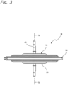
- Fig. 3 is a side view of the axial gap-type motor M.
- the axial gap-type motor M of this embodiment includes first and second rotors 10 and 20 each having a disk shape, a stator 30 sandwiched between the first and second rotors 10 and 20 in an axial direction, and a shaft 40 rotatably supported by the stator 30.
- the axial gap-type motor M is a 10-pole 12-slot motor.
- the first rotor 10 includes a disk-shaped magnet member 11 and a fixing portion 12 provided at a center portion of the disk-shaped magnet member 11.
- the shaft 40 is fixed to an inner periphery of the fixing portion 12.
- the disk-shaped magnet member 11 is a plastic magnet having a polar anisotropic orientation, and includes an outer peripheral portion 11a having an annular shape and an inner peripheral portion 11b formed on an inner periphery of the outer peripheral portion 11a and bulging outward in the axial direction of the shaft 40 (upward in Figs. 1 to 3 ).
- S poles and N poles are alternately arranged in a circumferential direction.
- the second rotor 20 includes a disk-shaped magnet member 21 and a fixing portion 22 provided at a center portion of the disk-shaped magnet member 21.
- the shaft 40 is fixed to an inner periphery of the fixing portion 22.
- the disk-shaped magnet member 21 is a plastic magnet having a polar anisotropic orientation, and includes an outer peripheral portion 21a having an annular shape and an inner peripheral portion 21b formed on an inner periphery of the outer peripheral portion 21a and bulging outward in the axial direction of the shaft 40 (downward in Figs. 1 to 3 ).
- S poles and N poles are alternately arranged in the circumferential direction.
- Fig. 4 is a cross-sectional view taken along line IV-IV in Fig. 3
- Fig. 5 is a perspective view of the stator 30 with a resin-molded portion 31 removed
- Fig. 6 is an exploded perspective view of the stator 30 with the resin-molded portion 31 removed.
- "400" denotes a bushing that leads out power source lines Lu, Lv, and Lw.
- the stator 30 includes 12 split cores 100 arranged in an annular pattern, a connection plate 200 to which the split cores 100 are fixed, a bearing holding portion 300 fixed to a center of the connection plate 200, a first bearing 301 disposed adjacent to the first rotor 10 in the bearing holding portion 300, a second bearing 302 disposed adjacent to the second rotor 20 in the bearing holding portion 300, and the resin-molded portion 31 having a disk shape and formed by resin molding the split cores 100, the connection plate 200, and the bearing holding portion 300.
- the split cores 100 each includes a stator core 110, a coil 120 wound around the stator core 110, and an insulator 130 that insulates the stator core 110 from the coil 120.
- the stator core 110 faces the first rotor 10 in the axial direction of the first rotor 10 with an air gap G1 interposed between the stator core 110 and the first rotor 10, and faces the second rotor 20 in the axial direction of the second rotor 20 with an air gap G2 interposed between the stator core 110 and the second rotor 20.
- the air gaps G1 and G2 are, for example, 0.5 mm to 1 mm.
- Fig. 7 is a perspective view of the connection plate 200 of the stator 30 and the power source lines Lu, Lv, and Lw
- Fig. 8 is an exploded perspective view of the connection plate 200 and the power source lines Lu, Lv, and Lw.
- the connection plate 200 includes an annular disk portion 201 having a hole 201a at its center and a cylindrical portion 202 extending toward one side in the axial direction along an inner periphery of the hole 201a of the disk portion 201.
- the annular disk portion 201 is provided with 12 press-fitting portions 203 at intervals in the circumferential direction, a first terminal Tc1 being press-fitted into each of the press-fitting portions 203.
- the first terminal Tc1 is an example of an electric connecting terminal. Although not limited, a mag-mate terminal is used as the first terminal Tc1 in this embodiment.
- the split cores 100 having the coils 120 to which U-phase, W-phase, and V-phase voltages are applied are each fixed to a corresponding one of the press-fitting portions 203. How to fix is illustrated in Figs. 9 and 10 .
- the power source line Lu is connected to the corresponding press-fitting portion 203 to which the split core 100 (magnetic pole U1 in Fig. 12 ) is fixed via a second terminal Tc2.
- the power source line Lv is connected to the corresponding press-fitting portion 203 to which the split core 100 (magnetic pole V2 in Fig. 12 ) is fixed via the second terminal Tc2.
- the power source line Lw is connected to the corresponding press-fitting portion 203 to which the split core 100 (magnetic pole W1 in Fig. 12 ) is fixed via the second terminal Tc2.
- a tab terminal connectable to a mag-mate terminal is used as the second terminal Tc2 in this embodiment.
- the first terminal Tc1 is a female terminal made of a conductive metal.
- the second terminal Tc2 is made of a conductive metal and is a male terminal corresponding to the first terminal Tc1 that is a female terminal.
- the second terminal Tc2 is fitted into a receiving portion of the first terminal Tc1, the first terminal Tc1 and the second terminal Tc2 are electrically connected to each other.
- each press-fitting portion 203 across which the outgoing line 121 from the corresponding coil 120 extends the outgoing line 121 extending from the coil 120 is fitted into the connection groove of the first terminal Tc1 with the first terminal Tc1 press-fitted into the press-fitting portion 203, so that the first terminal Tc1 and the coil 120 are electrically connected to each other.
- the connecting lines Luc1, Lvc1, and Lwc1 are each fitted into the connection groove of the corresponding first terminal Tc1 with the first terminal Tc1 press-fitted into the press-fitting portion 203, so that the connecting lines Luc1, Lvc1, and Lwc1 and the coils 120 are electrically connected to each other.
- Fig. 9 is a perspective view of the connection plate 200 and a pair of split cores 100 before assembly.
- Fig. 9 illustrates the connection plate 200, and a split core 100 (magnetic pole U3) and a split core 100 (magnetic pole U4) adjacent to each other.
- the coils 120 of the pair of split cores 100 are connected in series via a transition line 122.
- the stator core 110 of each split core 100 includes a first core portion 101, a second core portion 102, and a third core portion 103 each having an H shape but different in size from each other.
- the second core portion 102 is larger in width in the circumferential direction than the first core portion 101
- the third core portion 103 is larger in width in the circumferential direction than the second core portion 102.
- the first core portion 101, the second core portion 102, and the third core portion 103 are arranged in this order from a side adjacent to the connection plate 200 toward the outer side in the radial direction.
- the first core portion 101, the second core portion 102, and the third core portion 103 are each formed by stacking H-shaped steel plates in the radial direction.
- the insulator 130 includes a cylindrical portion (not illustrated) around which the coil 120 is wound, and a first flange portion 131 and a second flange portion 132 that are provided at both ends of the cylindrical portion and between which the coil 120 is sandwiched in the axial direction.
- a hook portion 133 on which the transition line 122 is hooked is provided at a side adjacent to the connection plate 200 of the first flange portion 131 illustrated on the upper side in Fig. 9 .
- a projection 134 extending toward the inner side in the radial direction relative to the stator core 110 is provided at a side adjacent to the connection plate 200 of the second flange portion 132 illustrated on the lower side in Fig. 9 .
- the projection 134 is provided with a cutout 135 having a square shape and a round hole 136.
- the cutout 135 is an example of a positioning portion.
- positioning portion is not limited to the cutout 135, and may be any other form that can be fitted to the connection plate.
- reference numerals 211, 212, 213 denote protrusions provided on an outer peripheral surface of the cylindrical portion 202 of the connection plate 200 and positions the connecting lines Luc1, Lvc1, Lwc1, and Lnc1 (see Fig. 18 ).
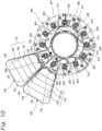
- Fig. 10 is a plane view of the connection plate 200 and the pair of split cores 100 that have been assembled. As illustrated in Fig. 10 , the cutout 135 of the insulator 130 and the press-fitting portion 203 of the connection plate 200 are fitted to each other, and each split core 100 including the stator core 110 and the coil 120 is positioned relative to the connection plate 200.
- connection plate 200 is inserted into the round hole 136 of the insulator 130 to assist in positioning of the split core 100 relative to the connection plate 200.
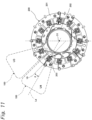
- each press-fitting portion 203 is provided on the connection plate 200 so as to allow the outgoing line 121 of the coil 120 wound around the stator core 110 to be routed at an acute angle ⁇ relative to a center line La of the stator core 110 along the radial direction of the stator 30.
- a straight line along an outgoing direction of the outgoing line 121 from the coil 120 is Lb
- an angle formed by the straight line Lb and the center line La is ⁇ .
- Fig. 12 is a plan view of a connection between the connection plate 200 and the power source lines Lu, Lv, and Lw.
- the stator cores 110 and the coils 120 wound around the stator cores 110 form magnetic poles U1, U2, U3, and U4, magnetic poles W1, W2, W3, and W4, and magnetic poles V1, V2, V3, and V4.
- the power source line Lu through which a U-phase voltage is supplied to the coils 120 of the magnetic poles U1, U2, U3, and U4 passes through between the magnetic poles U1 and U2 and is electrically connected to the outgoing line 121 drawn out from the coil 120 of the magnetic pole U1 illustrated in Fig. 19 .
- the power source line Lv through which a V-phase voltage is supplied to the coils 120 of the magnetic poles V1, V2, V3, and V4 passes through between the magnetic poles V1 and V2 and is electrically connected to the outgoing line 121 drawn out from the coil 120 of the magnetic pole V2 illustrated in Fig. 20 .
- the power source line Lw through which a W-phase voltage is supplied to the coils 120 of the magnetic poles W1, W2, W3, and W4 passes through between the magnetic poles W1 and W2 and is electrically connected to the outgoing line 121 drawn out from the coil 120 of the magnetic pole W1 illustrated in Fig. 21 .
- the outgoing line 121 drawn out from the coil 120 of the magnetic pole U1 is electrically connected to the power source line Lu on the inner side in the radial direction of the stator core 110 relative to an inner peripheral end of the stator core 110.
- the outgoing line 121 drawn out from the coil 120 of the magnetic pole V2 is electrically connected to the power source line Lv on the inner side in the radial direction of the stator core 110 relative to the inner peripheral end of the stator core 110.
- the outgoing line 121 drawn out from the coil 120 of the magnetic pole W1 is electrically connected to the power source line Lw on the inner side in the radial direction relative of the stator core 110 to the inner peripheral end of the stator core 110.
- a pair of magnetic poles that is, the magnetic poles U1 and U2, adjacent to each other and having one ends of their respective coils 120 connected to each other
- a pair of magnetic poles that is, the magnetic poles U3 and U4, having one ends of their respective coils 120 connected to each other are arranged point-symmetrically with respect to a center O1 of the stator 30.
- a pair of magnetic poles that is, the magnetic poles V1 and V2, adjacent to each other and having one ends of their respective coils 120 connected to each other, and a pair of magnetic poles, that is the magnetic poles V3 and V4, having one ends of their respective coils 120 connected to each other are arranged point-symmetrically with respect to the center O1 of the stator 30.
- a pair of magnetic poles that is, the magnetic poles W1 and W2, adjacent to each other and having one ends of their respective coils 120 connected to each other
- a pair of magnetic poles that is, the magnetic poles W3 and W4, having one ends of their respective coils 120 connected to each other are arranged point-symmetrically with respect to the center O1 of the stator 30.
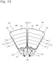
- Fig. 13 is a plan view of a pair of split cores 100, and as illustrated in Fig. 13 , a gap S is provided between the split cores 100 adjacent to each other.
- Fig. 14 is a plan view of the power source line Lw and the pair of split cores 100 with the power source line routed to the pair of split cores 100.
- the power source line Lw is routed from the outer side in the radial direction toward the inner side in the radial direction through the gap S between the split core 100 (magnetic pole W1) and the split core 100 (magnetic pole W2).
- the power source line Lw passes through between a plane parallel to an end surface of the first flange portion 131 of the insulator 130 and a plane parallel to a surface of the stator core 110 facing the first rotor 10.
- the power source line Lu and the power source line Lv are routed through the gap S between the other split cores 100 in a similar manner.
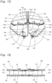
- Fig. 15 is an enlarged perspective view of a main part of the pair of split cores 100.
- the first flange portion 131 of the insulator 130 is provided with a step 131a at a portion facing the first flange portion 131 of the insulator 130 of the adjacent split core 100 and on the inner side in the radial direction.
- the step 131a of the first flange portion 131 of the insulator 130 facilitates the routing of the power source lines Lu, Lv, and Lw.
- 138 denotes a holding portion that holds an end of the outgoing line 121.
- the end of the outgoing line 121 extending from the coil 120 is wound around the holding portion 138.
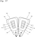
- Fig. 16 is a side view of the pair of split cores 100 as viewed from the inner side in the radial direction
- Fig. 17 is a cross-sectional view taken along line XVII-XVII in Fig. 16 .
- a gap between the coils 120 is narrowest.
- the step 131a of the first flange portion 131 of the insulator 130 illustrated in Fig. 15 is used to bypass the narrow region between the coils 120. That is, the power source lines Lu, Lv, and Lw pass through between the coils 120 from the outer side in the radial direction of the stator 30, and the power source lines Lu, Lv, and Lw are routed to pass through the step 131a on the outer side of the coil end in the region A.
- the coils 120 of each phase are connected in series.
- the series connection refers to a configuration where all coils to which the voltage of the same phase is applied are connected in series.
- Fig. 18 is a plan view of the connection plate 200.
- Fig. 18 illustrates an area where the split cores 100 corresponding to the magnetic poles U1 to U4, V1 to V4, and W1 to W4 are arranged.
- the split cores 100 illustrated in Fig. 6
- the split cores 100 are arranged in the order of U1, U2, V1, V2, W1, W2, U3, U4, V3, V4, W3, and W4 in the counterclockwise direction.
- Fig. 18 "Luc1" denotes a connecting line that electrically connects the outgoing line 121 of the magnetic pole U2 to the outgoing line 121 of the magnetic pole U4.
- Lvc1 denotes a connecting line that electrically connects the outgoing line 121 of the coil 120 of the magnetic pole V1 to the outgoing line 121 of the coil 120 of the magnetic pole V3.
- Lwc1 denotes a connecting line that electrically connects the outgoing line 121 of the magnetic pole W2 to the outgoing line 121 of the magnetic pole W4.
- Lnc1 denotes a connecting line that electrically connects the outgoing line 121 of the magnetic pole U3 to the outgoing line 121 of the magnetic pole V4 and that electrically connects the outgoing line 121 of the magnetic pole V4 to the outgoing line 121 of the magnetic pole W3.
- the connecting line electrically connects one of the outgoing lines 121 of the magnetic pole U3, the magnetic pole V4, and the magnetic pole W3 to the other two of the outgoing lines 121 of the magnetic pole U3, the magnetic pole V4, and the magnetic pole W3.
- the protrusions 211, 212, and 213 for positioning the connecting lines Luc1, Lvc1, Lwc1, and Lnc1 are provided on the outer peripheral surface of the cylindrical portion 202 of the connection plate 200.
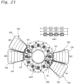
- Fig. 19 illustrates a U-phase connection (series connection) of the stator 30
- Fig. 20 illustrates a V-phase connection (series connection) of the stator 30
- Fig. 21 illustrates a W-phase connection (series connection) of the stator 30.
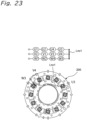
- Fig. 22 illustrates a neutral point connection of the stator 30, and Fig. 23 illustrates the connecting line Lnc 1 of the connection plate 200.
- the outgoing lines 121 drawn from the coils 120 are electrically connected to the power source lines Lu, Lv, and Lw on the inner sides in the radial direction of the stator cores 110 relative to the inner peripheral ends of the stator cores 110, so that a magnet outer diameter of the first and second rotors 10 and 20 can be made larger than a case where the outgoing lines 121 drawn from the coils 120 are electrically connected to the power source lines Lu, Lv, and Lw on the outer sides in the radial direction the stator cores 110, thereby making it possible to achieve higher output and higher efficiency.
- connection plate 200 the connecting lines Luc1, Lvc1, Lwc1, and Lnc1 electrically connecting the outgoing lines 121 of the coils 120 are routed in the connection plate 200, so that it is possible to facilitate the routing work such as connection between the coils 120 by manufacturing in advance the connection plate 200 in which the connecting lines Luc1, Lvc1, Lwc1, and Lnc1 are routed.
- connection plate 200 it is possible to facilitate the establishment of electrical connection between the outgoing lines 121 of the coils 120 and the connecting lines Luc1, Lvc1, Lwc1, and Lnc1 by press-fitting the first terminal Tc1 (electric connecting terminal) into each press-fitting portion 203 of the connection plate 200.
- connection plate 200 the press-fitting portion 203 of the connection plate 200 are fitted into the cutout 135 (positioning portion) provided in the projection 134 of the insulator 130 to position the stator core 110 and the coil 120 relative to the connection plate 200, so that it is possible to facilitate the assembly work of the stator core 110 and the coil 120.
- each press-fitting portion 203 is provided in the connection plate 200 so as to allow the outgoing line 121 of the coil 120 wound around the stator core 110 to be routed at the acute angle ⁇ relative to the center line La of the stator core 110 along the radial direction of the stator 30, and the press-fitting portion 203 is provided at a position along the outgoing direction of the outgoing line 121 drawn out from the outer periphery of the coil 120 (direction of the tangent to the outer periphery of the coil 120), so that it is possible to establish, in a smooth manner, the connection between the outgoing line 121 and each of the connecting lines Luc1, Lvc1, Lwc1, Lnc1 at the press-fitting portion 203.
- connection plate 200 the cylindrical portion 202 extending in the axial direction of the first and second rotors 10 and 20 is provided at the center portion of the connection plate 200, so that it is possible to guide the routing work of the connecting lines Luc1, Lvc1, Lwc1, and Lnc1 in the connection plate 200.
- connection lines Luc1, Lvc1, Lwc1, and Lnc1 are positioned by the protrusions 211, 212, and 213 provided on the outer peripheral surface of the cylindrical portion 202 of the connection plate 200, so that it is possible to guide and hold, in a simple manner, the connecting lines Luc1, Lvc1, Lwc1, and Lnc1 in the connection plate 200 during the routing work, which increases work efficiency.
- connection plate 200 the ends of the connecting lines Luc1, Lvc1, Lwc1, and Lnc1 are held by a holding portion 205 provided in the outer peripheral portion of the connection plate 200, so that it is possible to position, in a reliable manner, the connecting lines Luc1, Lvc1, Lwc1, and Lnc1 in the connection plate 200.
- Fig. 24 is a plan view of a connection plate 200 of an axial gap-type motor M of a second embodiment of the present disclosure.
- the coils 120 of each phase are connected in series, but the axial gap-type motor M of the second embodiment includes, as illustrated in Fig. 24 , the connection plate 200 in which the coils 120 are connected in parallel.
- the parallel connection refers to a configuration where at least two coils to which the voltage of the same phase is applied are connected in parallel.
- Fig. 24 illustrates an area where the split cores 100 of the magnetic poles U1 to U4, V1 to V4, and W1 to W4 are arranged.
- the split cores 100 illustrated in Fig. 6
- the split cores 100 are arranged in the order of U1, U2, V1, V2, W1, W2, U3, U4, V3, V4, W3, and W4 in the counterclockwise direction.
- Fig. 24 "Luc2" denotes a connecting line that electrically connects the outgoing line 121 of the magnetic pole U1 to the outgoing line 121 of the magnetic pole U4.
- Lvc2 denotes a connecting line that electrically connects the outgoing line 121 of the coil 120 of the magnetic pole V2 to the outgoing line 121 of the coil 120 of the magnetic pole V3.
- Lwc2 denotes a connecting line that electrically connects the outgoing line 121 of the magnetic pole W1 to the outgoing line 121 of the magnetic pole W4.
- Lnc1 denotes a connecting line that electrically connects the outgoing line 121 of the magnetic pole U3 to the outgoing line 121 of the magnetic pole V4 and that electrically connects the outgoing line 121 of the magnetic pole V4 to the outgoing line 121 of the magnetic pole W3.
- the connecting line electrically connects one of the outgoing lines 121 of the magnetic pole U3, the magnetic pole V4, and the magnetic pole W3 to the other two of the outgoing lines 121 of the magnetic pole U3, the magnetic pole V4, and the magnetic pole W3.
- Lnc2 denotes a connecting line that electrically connects the outgoing line 121 of the magnetic pole V1 to the outgoing line 121 of the magnetic pole U2 and that electrically connects the outgoing line 121 of the magnetic pole U2 to the outgoing line 121 of the magnetic pole W2.
- the connecting line electrically connects one of the outgoing lines 121 of the magnetic pole V1, the magnetic pole U2, and the magnetic pole W2 to the other two of the outgoing lines 121 of the magnetic pole V1, the magnetic pole U2, and the magnetic pole W2.
- Fig. 25 illustrates a U-phase connection (parallel connection) of the stator 30
- Fig. 26 illustrates a V-phase connection (parallel connection) of the stator 30
- Fig. 27 illustrates a W-phase connection (parallel connection) of the stator 30.
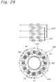
- Fig. 28 illustrates a neutral point connection of the stator 30, and Fig. 29 illustrates the connecting lines Lnc1 and Lnc2 of the connection plate 200.
- the axial gap-type motor M of the second embodiment produces the same effect as produced by the axial gap-type motor M of the first embodiment.
- the axial gap-type motors M of the first and second embodiments can be each used as a highly versatile axial gap-type motor adapted to both series connection of coils and parallel connection of coils.
- the axial gap-type motor M including the first rotor 10 and the second rotor 20 is provided, but the present disclosure may be applied to an axial gap-type motor including one rotor.
- the stator core may be provided with a back yoke.
- the 10-pole 12-slot axial gap-type motor M has been described, but the number of poles and the number of slots are not limited thereto, and the present disclosure may be applied to axial gap-type motors having other configurations where different numbers of poles and slots are provided.
- Fig. 30 is a circuit diagram of an air conditioner using an axial gap-type motor M of a third embodiment of the present disclosure. This air conditioner uses either of the axial gap-type motors M of the first and second embodiments.
- the air conditioner of the third embodiment includes an indoor unit U100 installed in an indoor space to be air-conditioned and an outdoor unit U200 installed outdoors.
- the indoor unit U100 of the air conditioner includes an indoor heat exchanger 504 having one end connected to a refrigerant pipe L4 (connection pipe) and the other end connected to a refrigerant pipe L5 (connection pipe), an indoor fan 506 that supplies air to the indoor heat exchanger 504, and the axial gap-type motor M that drives the indoor fan 506.
- a sirocco fan is used as the indoor fan 506.
- the indoor fan 506 is an example of a fan.
- the outdoor unit U200 of the air conditioner includes a compressor CMP 1, a four-way switching valve 501, an outdoor heat exchanger 502, an expansion valve 503 as an example of an expansion mechanism, an accumulator 507, an outdoor fan 505 that sends air to the outdoor heat exchanger 502.
- the compressor CMP1 has a discharge side connected to a first port a of the four-way switching valve 501 via the refrigerant pipe L1.
- the four-way switching valve 501 has a second port b connected to one end of the outdoor heat exchanger 502 via the refrigerant pipe L2.
- the outdoor heat exchanger 502 has the other end connected to one end of the expansion valve 503 via the refrigerant pipe L3, and the expansion valve 503 has the other end connected to one end of the refrigerant pipe L4 (connection pipe).
- the refrigerant pipe L5 (connection pipe) has one end connected to a third port c of the four-way switching valve 501.
- the four-way switching valve 501 has a fourth port d connected to a suction side of the compressor CMP1 via a refrigerant pipe L6, the accumulator 507, and a suction pipe L7.
- the air conditioner using the axial gap-type motor M of the first and second embodiments for driving the indoor fan 506 can increase air blowing performance.
- the air conditioner that performs cooling operation and heating operation has been described, but the air conditioner is not limited to such a configuration, and the present disclosure may be applied to an air purifier and the like.
- An axial gap-type motor M of a fourth embodiment of the present disclosure has a configuration similar to the configuration described with reference to Figs. 1 to 17 . Therefore, the description of the similar configuration described above will be omitted.
- protrusions of the cylindrical portion 202 not denoted by the reference numerals 211, 212, and 213 in Fig. 9 are also included in the protrusions that position the connecting lines Luc1, Lvc1, Lwc1, and Lnc1.
- the step 131a is an example of the holding portion that holds the power source lines Lu, Lv, and Lw.
- Fig. 31 is a plan view of a connection plate 200, and a connection diagram of series connection is illustrated on the upper side of Fig. 31 .
- U1 to U4, V1 to V4, and W1 to W4 indicate areas where the split cores 100 corresponding to the magnetic poles U1 to U4, V1 to V4, and W1 to W4 are arranged.
- the split cores 100 illustrated in Fig. 31 .
- Fig. 31 "Luc1" denotes a connecting line that electrically connects the outgoing line 121 of the magnetic pole U2 to the outgoing line 121 of the magnetic pole U4.
- Lvc1 denotes a connecting line that electrically connects the outgoing line 121 of the coil 120 of the magnetic pole V1 to the outgoing line 121 of the coil 120 of the magnetic pole V3.
- Lwc1 denotes a connecting line that electrically connects the outgoing line 121 of the magnetic pole W2 to the outgoing line 121 of the magnetic pole W4.
- Lnc1 denotes a connecting line that electrically connects the outgoing line 121 of the magnetic pole U3 to the outgoing line 121 of the magnetic pole V4 and that electrically connects the outgoing line 121 of the magnetic pole V4 to the outgoing line 121 of the magnetic pole W3.
- the connecting line electrically connects one of the outgoing lines 121 of the magnetic pole U3, the magnetic pole V4, and the magnetic pole W3 to the other two of the outgoing lines 121 of the magnetic pole U3, the magnetic pole V4, and the magnetic pole W3.
- the protrusions 211, 212, and 213 for positioning the connecting lines Luc1, Lvc1, Lwc1, and Lnc1 are provided on the outer peripheral surface of the cylindrical portion 202 of the connection plate 200.
- the power source lines Lu, Lv, and Lw routed, through between the stator cores 110, from the outer side in the radial direction of the stator 30 to the inner side in the radial direction of the stator 30 relative to the inner peripheral end of each stator core 110 are electrically connected to the outgoing lines 121 drawn out from the coils 120 on the inner side in the radial direction of the stator cores 110.
- the power source lines Lu, Lv, and Lw are held by the step 131a (holding portion) provided at portions of the insulators 130 adjacent to each other, the portions facing each other and being located on the one sides of the insulators 130 in the axial direction of the stator 30 and the inner sides of the insulators 130 in the radial direction of the stator 30.
- the magnet outer diameter of the first and second rotors 10 and 20 can be made larger than a case where the outgoing lines 121 extending from the coils 120 are electrically connected to the power source lines Lu, Lv, and Lw on the outer sides in the radial direction of the stator cores 110, so that it is possible to achieve higher output and higher efficiency.
- connection plate 200 the connecting lines Luc1, Lvc1, Lwc1, and Lnc1 electrically connecting the outgoing lines 121 of the coils 120 are routed in the connection plate 200, so that it is possible to facilitate the routing work such as connection between the coils 120 by manufacturing in advance the connection plate 200 in which the connecting lines Luc1, Lvc1, Lwc1, and Lnc1 are routed.
- connection plate 200 it is possible to facilitate the establishment of electrical connection between the outgoing lines 121 of the coils 120 and the connecting lines Luc1, Lvc1, Lwc1, and Lnc1 by press-fitting the first terminal Tc1 (electric connecting terminal) into each press-fitting portion 203 of the connection plate 200.
- cutout 135 positioning portion
- the cutout 135 positioning portion
- the press-fitting portion 203 of the connection plate 200 are fitted to each other to position the stator core 110 and the coil 120 relative to the connection plate 200, so that it is possible to facilitate the assembly work of the stator core 110 and the coil 120.
- connection plate 200 the cylindrical portion 202 extending in the axial direction of the first and second rotors 10 and 20 is provided at the center portion of the connection plate 200, so that it is possible to guide the routing work of the connecting lines Luc1, Lvc1, Lwc1, and Lnc1 in the connection plate 200.
- connection lines Luc1, Lvc1, Lwc1, and Lnc1 are positioned by the protrusions 211, 212, and 213 provided on the outer peripheral surface of the cylindrical portion 202 of the connection plate 200, so that it is possible to guide and hold, in a simple manner, the connecting lines Luc1, Lvc1, Lwc1, and Lnc1 in the connection plate 200 during the routing work, which increases work efficiency.
- connection plate 200 the ends of the connecting lines Luc1, Lvc1, Lwc1, and Lnc1 are held by a holding portion 205 provided in the outer peripheral portion of the connection plate 200, so that it is possible to position, in a reliable manner, the connecting lines Luc1, Lvc1, Lwc1, and Lnc1 in the connection plate 200.
- Fig. 32 is a plan view of a connection plate 200 of an axial gap-type motor M of a fifth embodiment of the present disclosure.
- the coils 120 of each phase are connected in series, but the axial gap-type motor M of the fifth embodiment includes, as illustrated in Fig. 32 , a connection plate 200 in which the coils 120 are connected in parallel.
- the parallel connection refers to a configuration where at least two coils to which the voltage of the same phase is applied are connected in parallel.
- a connection diagram of the parallel connection is illustrated on the upper side of Fig. 32 .
- U1 to U4, V1 to V4, and W1 to W4 indicate areas where the split cores 100 of the magnetic poles U1 to U4, V1 to V4, and W1 to W4 are arranged.
- the split cores 100 illustrated in Fig. 6
- the split cores 100 are arranged in the order of U1, U2, V1, V2, W1, W2, U3, U4, V3, V4, W3, and W4 in the counterclockwise direction.
- Fig. 32 "Luc2" denotes a connecting line that electrically connects the outgoing line 121 of the magnetic pole U1 to the outgoing line 121 of the magnetic pole U4.
- Lvc2 denotes a connecting line that electrically connects the outgoing line 121 of the coil 120 of the magnetic pole V2 to the outgoing line 121 of the coil 120 of the magnetic pole V3.
- Lwc2 denotes a connecting line that electrically connects the outgoing line 121 of the magnetic pole W1 to the outgoing line 121 of the magnetic pole W4.
- Lnc1 denotes a connecting line that electrically connects the outgoing line 121 of the magnetic pole U3 to the outgoing line 121 of the magnetic pole V4 and that electrically connects the outgoing line 121 of the magnetic pole V4 to the outgoing line 121 of the magnetic pole W3.
- the connecting line electrically connects one of the outgoing lines 121 of the magnetic pole U3, the magnetic pole V4, and the magnetic pole W3 to the other two of the outgoing lines 121 of the magnetic pole U3, the magnetic pole V4, and the magnetic pole W3.
- Lnc2 denotes a connecting line that electrically connects the outgoing line 121 of the magnetic pole V1 to the outgoing line 121 of the magnetic pole U2 and that electrically connects the outgoing line 121 of the magnetic pole U2 to the outgoing line 121 of the magnetic pole W2.
- the connecting line electrically connects one of the outgoing lines 121 of the magnetic pole V1, the magnetic pole U2, and the magnetic pole W2 to the other two of the outgoing lines 121 of the magnetic pole V1, the magnetic pole U2, and the magnetic pole W2.
- the axial gap-type motor M of the fifth embodiment produces the same effect as produced by the axial gap-type motor M of the fourth embodiment.
- the axial gap-type motors M of the fourth and fifth embodiments can be each used as, by using the connection plate 200, a highly versatile axial gap-type motor adapted to both series connection of coils and parallel connection of coils.
- the axial gap-type motor M including the first rotor 10 and the second rotor 20 is provided, but the present disclosure may be applied to an axial gap-type motor including one rotor.
- the stator core may be provided with a back yoke.
- the 10-pole 12-slot axial gap-type motor M has been described, but the number of poles and the number of slots are not limited thereto, and the present disclosure may be applied to axial gap-type motors having other configurations where different numbers of poles and slots are provided.
- Fig. 33 is a circuit diagram of an air conditioner using an axial gap-type motor M of a sixth embodiment of the present disclosure. This air conditioner uses either of the axial gap-type motors M of the fourth and fifth embodiments.
- the air conditioner of the sixth embodiment includes the indoor unit U100 installed in an indoor space to be air-conditioned and the outdoor unit U200 installed outdoors.
- the indoor unit U100 of the air conditioner includes an indoor heat exchanger 504 having one end connected to a refrigerant pipe L4 (connection pipe) and the other end connected to a refrigerant pipe L5 (connection pipe), an indoor fan 506 that supplies air to the indoor heat exchanger 504, and the axial gap-type motor M that drives the indoor fan 506.
- a sirocco fan is used as the indoor fan 506.
- the indoor fan 506 is an example of a fan.
- the outdoor unit U200 of the air conditioner includes a compressor CMP 1, a four-way switching valve 501, an outdoor heat exchanger 502, an expansion valve 503 as an example of an expansion mechanism, an accumulator 507, an outdoor fan 505 that sends air to the outdoor heat exchanger 502.
- the compressor CMP1 has a discharge side connected to a first port a of the four-way switching valve 501 via the refrigerant pipe L1.
- the four-way switching valve 501 has a second port b connected to one end of the outdoor heat exchanger 502 via the refrigerant pipe L2.
- the outdoor heat exchanger 502 has the other end connected to one end of the expansion valve 503 via the refrigerant pipe L3, and the expansion valve 503 has the other end connected to one end of the refrigerant pipe L4 (connection pipe).
- the refrigerant pipe L5 (connection pipe) has one end connected to a third port c of the four-way switching valve 501.
- the four-way switching valve 501 has a fourth port d connected to a suction side of the compressor CMP1 via a refrigerant pipe L6, the accumulator 507, and a suction pipe L7.
- the air conditioner using the axial gap-type motor M of the fourth and fifth embodiments for driving the indoor fan 506 can increase air blowing performance.
- the air conditioner that performs cooling operation and heating operation has been described, but the air conditioner is not limited to such a configuration, and the present disclosure may be applied to an air purifier and the like.
Landscapes
- Engineering & Computer Science (AREA)
- Power Engineering (AREA)
- Insulation, Fastening Of Motor, Generator Windings (AREA)
- Iron Core Of Rotating Electric Machines (AREA)
Abstract
Description
- The present disclosure relates to an axial gap-type motor and an air conditioner.
- There has been an axial gap-type motor in which a coil is connected to a power source line via a printed circuit board or an electric connecting terminal (see, for example,
JP 2013-118750 A - Patent Literature 1:
JP 2013-118750 A - In the axial gap-type motor, an input-side end to which the power source line is connected is provided on an outer side of a stator in a radial direction, which restricts an outer diameter of a stator core and leads to deterioration in motor magnetic characteristics. In such an axial gap-type motor, a restriction on an outer diameter of a stator core hinders higher output and higher efficiency.
- The present disclosure proposes an axial gap-type motor capable of achieving higher output and higher efficiency, and an air conditioner including the axial gap-type motor.
- An axial gap-type motor according to a first aspect of the present disclosure includes:
- a rotor; and
- a stator facing the rotor with an air gap interposed between the stator and the rotor in an axial direction of the rotor,
- in which the stator includes a plurality of stator cores arranged in an annular pattern and a coil wound around each of the stator cores, and
- outgoing lines drawn out from the coils are electrically connected to power source lines on inner sides in a radial direction of the stator cores relative to inner peripheral ends of the stator cores.
- According to the present disclosure, a magnet outer diameter of the rotor can be made larger than a case where the outgoing lines extending from the coils are electrically connected to the power source lines on the outer sides in the radial direction of the stator cores, so that it is possible to achieve higher output and higher efficiency.
- In addition, an axial gap-type motor according to a second aspect of the present disclosure is based on the axial gap motor according to the first aspect and further includes a connection plate in which connecting lines are routed, each of the connecting lines electrically connecting between the outgoing lines of the coils.
- According to the present disclosure, it is possible to facilitate the routing work such as connection between the coils by manufacturing in advance the connection plate in which the connecting lines are routed.
- In addition, an axial gap-type motor (M) according to a third aspect of the present disclosure is based on the axial gap motor according to the second aspect, in which the connection plate includes press-fitting portions into which are press-fitted, the outgoing lines of the coils electrically connecting to the connecting lines via the electric connecting terminals.
- According to the present disclosure, it is possible to facilitate the establishment of electrical connection between the outgoing lines of the coils and the connecting lines.
- In addition, an axial gap-type motor according to a fourth aspect of the present disclosure is based on the axial gap-type motor according to the third aspect, in which the stator includes insulators that insulate the stator cores from the coils,
- the insulators each include a projection extending toward the inner side in the radial direction of a corresponding one of the stator cores and a positioning portion provided in the projection, and
- the positioning portions of the insulators and the press-fitting portions of the connection plate are fitted to each other to position the stator cores and the coils relative to the connection plate.
- According to the present disclosure, it is possible to facilitate the assembly work of the stator cores and the coils.
- In addition, an axial gap-type motor according to a fifth aspect of the present disclosure is based on the axial gap-type motor according to the third aspect or the fourth aspect, in which the press-fitting portions are provided in the connection plate so as to allow the outgoing lines of the coils wound around the stator cores to be each routed at an acute angle relative to a center line of a corresponding one of the stator cores along a radial direction of the stator.
- According to the present disclosure, it is possible to establish, by providing each of the press-fitting portions at a position along the outgoing direction of the outgoing line drawn out from the outer periphery of the corresponding coil (direction of the tangent to the outer periphery of the coil), connection between the outgoing line and each of the connecting lines at the press-fitting portion in a smooth manner.
- In addition, an axial gap-type motor according to a sixth aspect of the present disclosure is based on the axial gap-type motor according to any one of the second aspect to the fifth aspect, in which a cylindrical portion extending in the axial direction of the rotor is provided in a center portion of the connection plate.
- According to the present disclosure, it is possible to guide the routing work of the connecting lines in the connection plate.
- In addition, an axial gap-type motor according to a seventh aspect of the present disclosure is based on the axial gap-type motor according to the sixth aspect, in which protrusions that position the connecting lines are provided on an outer peripheral surface of the cylindrical portion of the connection plate.
- According to the present disclosure, it is possible to guide and hold, in a simple manner, the connecting lines in the connection plate during the routing work, which increases work efficiency.
- In addition, an axial gap-type motor according to an eighth aspect of the present disclosure is based on the axial gap-type motor according to any one of the second aspect to the seventh aspect, in which holding portions that hold ends of the connecting lines are provided in an outer peripheral portion of the connection plate.
- According to the present disclosure, the ends of the connecting lines are held, so that it is possible to position, in a reliable manner, the connecting lines in the connection plate.
- In addition, an axial gap-type motor according to a ninth aspect of the present disclosure is based on the axial gap-type motor according to any one of the second aspect to the eighth aspect, in which the connection plate is configured to enable routing of the connecting lines to adapt to both series connection of the coils and parallel connection of the coils.
- According to the present disclosure, it is possible to implement a highly versatile axial gap-type motor adapted to both the series connection of the coils and the parallel connection of the coils.
- In addition, an axial gap-type motor according to a tenth aspect of the present disclosure is based on the axial gap-type motor according to any one of the first aspect to the ninth aspect, in which any one of a U-phase voltage, a V-phase voltage, or a W-phase voltage is applied to the coils via a corresponding one of the power source lines,
- the stator has magnetic poles formed by the coils and the stator cores around which the coils are wound,
- the magnetic poles in which the voltage of the same phase is applied to the coils include pairs of magnetic poles, each pair of magnetic poles corresponding to two of the magnetic poles adjacent to each other and having one ends of their respective coils connected to each other, and
- the pairs of magnetic poles are arranged point-symmetrically with respect to a center of the stator.
- In addition, an axial gap-type motor according to an eleventh aspect of the present disclosure is based on the axial gap-type motor according to the first aspect, in which the stator includes insulators that insulate the stator cores from the coils,
- the power source lines are routed, through between the stator cores, from an outer side in a radial direction of the stator to the inner side in the radial direction of the stator relative to the inner peripheral ends of the stator cores, and
- holding portions that hold the power source lines are provided at portions of the insulators adjacent to each other, the portions facing each other and being located on one sides of the insulators in an axial direction of the stator and on inner sides of the insulators in the radial direction of the stator.
- According to the present disclosure, the magnet outer diameter of the rotor can be made larger than a case where the outgoing lines extending from the coils are electrically connected to the power source lines on the outer sides in the radial direction of the stator cores, so that it is possible to achieve higher output and higher efficiency.
- In addition, an axial gap-type motor according to a twelfth aspect of the present disclosure is based on the axial gap-type motor according to the eleventh aspect and further includes a connection plate in which connecting lines are routed, each of the connecting lines electrically connecting between the outgoing lines drawn out from the coils.
- According to the present disclosure, it is possible to facilitate the routing work such as connection between the coils by manufacturing in advance the connection plate in which the connecting lines are routed.
- In addition, an air conditioner according to a thirteenth aspect of the present disclosure includes:
- the axial gap-type motor according to any one of the first aspect to the twelfth aspect; and
- a fan driven by the axial gap motor.
- According to the present disclosure, it is possible to increase air blowing performance by driving the fan with the axial gap-type motor capable of achieving higher output and higher efficiency.
- In addition, an axial gap-type motor according to a fourteenth aspect of the present disclosure is based on the axial gap-type motor according to the eleventh aspect or the twelfth aspect and includes a part of the configuration according to the second aspect to the tenth aspect.
- That is, the axial gap-type motor according to the fourteenth aspect of the present disclosure corresponds to an axial gap-type motor obtained by applying the part of the configuration according to the second aspect to the tenth aspect to the axial gap-type motor according to the eleventh aspect or the twelfth aspect.
- In addition, an air conditioner according to a fifteenth aspect of the present disclosure includes:
- the axial gap-type motor according to the fourteenth aspect; and
- a fan driven by the axial gap motor.
- An axial gap-type motor according to a sixteenth aspect of the present disclosure includes:
- a rotor; and
- a stator facing the rotor with an air gap interposed between the stator and the rotor in an axial direction of the rotor, in which the stator includes stator cores, coils wound around the stator cores, and insulators that insulate the stator cores from the coils,
- power source lines routed, through between the stator cores, from an outer side in a radial direction of the stator to an inner side in the radial direction of the stator relative to inner peripheral ends of the stator cores are electrically connected to outgoing lines drawn out from the coils on inner sides in the radial direction of the stator cores, and
- holding portions that hold the power source lines are provided at portions of the insulators adjacent to each other, the portions facing each other and being located on one sides of the insulators in an axial direction of the stator and on inner sides of the insulators in the radial direction of the stator.
- According to the present disclosure, a magnet outer diameter of the rotor can be made larger than a case where the outgoing lines extending from the coils are electrically connected to the power source lines on the outer sides in the radial direction of the stator cores, so that it is possible to achieve higher output and higher efficiency.
- In addition, an axial gap-type motor according to a seventeenth aspect of the present disclosure includes a connection plate in which connecting lines that electrically connect between the outgoing lines drawn out from the coils are routed.
- According to the present disclosure, it is possible to facilitate the routing work such as connection between the coils by manufacturing in advance the connection plate in which the connecting lines are routed.
- In addition, an air conditioner according to an eighteenth aspect of the present disclosure includes:
- the axial gap-type motor according to the sixteenth aspect or the seventeenth aspect; and
- a fan driven by the axial gap motor.
- According to the present disclosure, it is possible to increase air blowing performance by driving the fan with the axial gap-type motor capable of achieving higher output and higher efficiency.
-
-
Fig. 1 is an overall perspective view of an axial gap-type motor of a first embodiment of the present disclosure. -
Fig. 2 is an exploded perspective view of the axial gap-type motor of the first embodiment. -
Fig. 3 is a side view of the axial gap-type motor of the first embodiment. -
Fig. 4 is a cross-sectional view taken along line IV-IV inFig. 3 . -
Fig. 5 is an exploded perspective view of a stator of the first embodiment with a resin-molded portion removed. -
Fig. 6 is an exploded perspective view of the stator of the first embodiment with the resin-molded portion removed. -
Fig. 7 is a perspective view of a connection plate of the stator and a power source line of the first embodiment. -
Fig. 8 is an exploded perspective view of the connection plate and the power source line of the first embodiment. -
Fig. 9 is a perspective view of the connection plate and a pair of split cores of the first embodiment before assembly. -
Fig. 10 is a perspective view of the connection plate and the pair of split cores of the first embodiment that have been assembled. -
Fig. 11 is a plan view of the connection plate of the first embodiment. -
Fig. 12 is a plan view of a connection between the connection plate and the power source line of the first embodiment. -
Fig. 13 is a plan view of a pair of split cores of the first embodiment. -
Fig. 14 is a plan view of the power source line and the pair of split cores of the first embodiment with the power source line routed to the pair of split cores. -
Fig. 15 is an enlarged perspective view of a main part of the pair of split cores. -
Fig. 16 is a side view of the pair of split cores of the first embodiment as viewed from an inner side in a radial direction. -
Fig. 17 is a cross-sectional view taken along line XVII-XVII inFig. 16 . -
Fig. 18 is a plan view of the connection plate of the first embodiment. -
Fig. 19 is a diagram illustrating a U-phase connection (series connection) of the stator of the first embodiment. -
Fig. 20 is a diagram illustrating a V-phase connection (series connection) of the stator of the first embodiment. -
Fig. 21 is a diagram illustrating a W-phase connection (series connection) of the stator of the first embodiment. -
Fig. 22 is a diagram illustrating a neutral point connection of the stator of the first embodiment. -
Fig. 23 is a diagram illustrating a neutral point connecting line of the connection plate of the first embodiment. -
Fig. 24 is a plan view of a connection plate of an axial gap-type motor of a second embodiment of the present disclosure. -
Fig. 25 is a diagram illustrating a U-phase connection (parallel connection) of a stator of the second embodiment. -
Fig. 26 is a diagram illustrating a V-phase connection (parallel connection) of the stator of the second embodiment. -
Fig. 27 is a diagram illustrating a W-phase connection (parallel connection) of the stator of the second embodiment. -
Fig. 28 is a diagram illustrating a neutral point connection of the stator of the second embodiment. -
Fig. 29 is a diagram illustrating a neutral point connecting line of the connection plate of the second embodiment. -
Fig. 30 is a circuit diagram of an air conditioner using an axial gap-type motor of a third embodiment of the present disclosure. -
Fig. 31 is a plan view of a connection plate of an axial gap-type motor of a fourth embodiment of the present disclosure. -
Fig. 32 is a plan view of a connection plate of an axial gap-type motor of a fifth embodiment of the present disclosure. -
Fig. 33 is a circuit diagram of an air conditioner using an axial gap-type motor of a sixth embodiment of the present disclosure. - Embodiments will be described below. Note that, in the drawings, the same reference numerals represent the same or corresponding parts. In addition, the dimensions on the drawings, such as lengths, widths, thicknesses, and depths, are appropriately changed from actual scales for clarity and simplification of the drawings, and do not represent actual relative dimensions.
-
Fig. 1 is an overall perspective view of an axial gap-type motor M of a first embodiment of the present disclosure,Fig. 2 is an exploded perspective view of the axial gap-type motor M, andFig. 3 is a side view of the axial gap-type motor M. - As illustrated in
Figs. 1 to 3 , the axial gap-type motor M of this embodiment includes first andsecond rotors stator 30 sandwiched between the first andsecond rotors shaft 40 rotatably supported by thestator 30. The axial gap-type motor M is a 10-pole 12-slot motor. - The
first rotor 10 includes a disk-shapedmagnet member 11 and a fixingportion 12 provided at a center portion of the disk-shapedmagnet member 11. Theshaft 40 is fixed to an inner periphery of the fixingportion 12. - The disk-shaped
magnet member 11 is a plastic magnet having a polar anisotropic orientation, and includes an outerperipheral portion 11a having an annular shape and an innerperipheral portion 11b formed on an inner periphery of the outerperipheral portion 11a and bulging outward in the axial direction of the shaft 40 (upward inFigs. 1 to 3 ). In the outerperipheral portion 11a, S poles and N poles are alternately arranged in a circumferential direction. - In addition, the
second rotor 20 includes a disk-shapedmagnet member 21 and a fixingportion 22 provided at a center portion of the disk-shapedmagnet member 21. Theshaft 40 is fixed to an inner periphery of the fixingportion 22. - The disk-shaped
magnet member 21 is a plastic magnet having a polar anisotropic orientation, and includes an outerperipheral portion 21a having an annular shape and an innerperipheral portion 21b formed on an inner periphery of the outerperipheral portion 21a and bulging outward in the axial direction of the shaft 40 (downward inFigs. 1 to 3 ). In the outerperipheral portion 21a, S poles and N poles are alternately arranged in the circumferential direction. -
Fig. 4 is a cross-sectional view taken along line IV-IV inFig. 3 ,Fig. 5 is a perspective view of thestator 30 with a resin-moldedportion 31 removed, andFig. 6 is an exploded perspective view of thestator 30 with the resin-moldedportion 31 removed. InFigs. 5 and6 , "400" denotes a bushing that leads out power source lines Lu, Lv, and Lw. - As illustrated in
Figs. 4 ,5 , and6 , thestator 30 includes 12 splitcores 100 arranged in an annular pattern, aconnection plate 200 to which thesplit cores 100 are fixed, abearing holding portion 300 fixed to a center of theconnection plate 200, afirst bearing 301 disposed adjacent to thefirst rotor 10 in thebearing holding portion 300, asecond bearing 302 disposed adjacent to thesecond rotor 20 in thebearing holding portion 300, and the resin-moldedportion 31 having a disk shape and formed by resin molding thesplit cores 100, theconnection plate 200, and thebearing holding portion 300. - The
split cores 100 each includes astator core 110, acoil 120 wound around thestator core 110, and aninsulator 130 that insulates thestator core 110 from thecoil 120. - The
stator core 110 faces thefirst rotor 10 in the axial direction of thefirst rotor 10 with an air gap G1 interposed between thestator core 110 and thefirst rotor 10, and faces thesecond rotor 20 in the axial direction of thesecond rotor 20 with an air gap G2 interposed between thestator core 110 and thesecond rotor 20. The air gaps G1 and G2 are, for example, 0.5 mm to 1 mm. -
Fig. 7 is a perspective view of theconnection plate 200 of thestator 30 and the power source lines Lu, Lv, and Lw, andFig. 8 is an exploded perspective view of theconnection plate 200 and the power source lines Lu, Lv, and Lw. - As illustrated in
Figs. 7 and8 , theconnection plate 200 includes anannular disk portion 201 having ahole 201a at its center and acylindrical portion 202 extending toward one side in the axial direction along an inner periphery of thehole 201a of thedisk portion 201. Theannular disk portion 201 is provided with 12 press-fittingportions 203 at intervals in the circumferential direction, a first terminal Tc1 being press-fitted into each of the press-fittingportions 203. The first terminal Tc1 is an example of an electric connecting terminal. Although not limited, a mag-mate terminal is used as the first terminal Tc1 in this embodiment. - The
split cores 100 having thecoils 120 to which U-phase, W-phase, and V-phase voltages are applied are each fixed to a corresponding one of the press-fittingportions 203. How to fix is illustrated inFigs. 9 and10 . - The power source line Lu is connected to the corresponding press-fitting
portion 203 to which the split core 100 (magnetic pole U1 inFig. 12 ) is fixed via a second terminal Tc2. The power source line Lv is connected to the corresponding press-fittingportion 203 to which the split core 100 (magnetic pole V2 inFig. 12 ) is fixed via the second terminal Tc2. The power source line Lw is connected to the corresponding press-fittingportion 203 to which the split core 100 (magnetic pole W1 inFig. 12 ) is fixed via the second terminal Tc2. Although not limited, a tab terminal connectable to a mag-mate terminal is used as the second terminal Tc2 in this embodiment. - The first terminal Tc1 is a female terminal made of a conductive metal. The second terminal Tc2 is made of a conductive metal and is a male terminal corresponding to the first terminal Tc1 that is a female terminal. When the second terminal Tc2 is fitted into a receiving portion of the first terminal Tc1, the first terminal Tc1 and the second terminal Tc2 are electrically connected to each other.
- The first terminal Tc1 is press-fitted into each press-fitting
portion 203 provided in theconnection plate 200. In addition, the first terminal Tc1 includes a connection groove (not illustrated) for establishing electrical connection with an outgoing line 121 (illustrated inFig. 9 ) drawn out from eachcoil 120, and the receiving portion (not illustrated) connectable to the second terminal Tc2. - In each press-fitting
portion 203 across which theoutgoing line 121 from the correspondingcoil 120 extends, theoutgoing line 121 extending from thecoil 120 is fitted into the connection groove of the first terminal Tc1 with the first terminal Tc1 press-fitted into the press-fittingportion 203, so that the first terminal Tc1 and thecoil 120 are electrically connected to each other. - At the same time, in the press-fitting
portions 203 across which connecting lines Luc1, Lvc1, and Lwc1 routed in advance in theconnection plate 200 extend, the connecting lines Luc1, Lvc1, and Lwc1 are each fitted into the connection groove of the corresponding first terminal Tc1 with the first terminal Tc1 press-fitted into the press-fittingportion 203, so that the connecting lines Luc1, Lvc1, and Lwc1 and thecoils 120 are electrically connected to each other. -
Fig. 9 is a perspective view of theconnection plate 200 and a pair ofsplit cores 100 before assembly.Fig. 9 illustrates theconnection plate 200, and a split core 100 (magnetic pole U3) and a split core 100 (magnetic pole U4) adjacent to each other. - As illustrated in
Fig. 9 , thecoils 120 of the pair of split cores 100 (magnetic poles U3, U4) are connected in series via atransition line 122. - The
stator core 110 of eachsplit core 100 includes afirst core portion 101, asecond core portion 102, and athird core portion 103 each having an H shape but different in size from each other. Thesecond core portion 102 is larger in width in the circumferential direction than thefirst core portion 101, and thethird core portion 103 is larger in width in the circumferential direction than thesecond core portion 102. - The
first core portion 101, thesecond core portion 102, and thethird core portion 103 are arranged in this order from a side adjacent to theconnection plate 200 toward the outer side in the radial direction. Thefirst core portion 101, thesecond core portion 102, and thethird core portion 103 are each formed by stacking H-shaped steel plates in the radial direction. - The
insulator 130 includes a cylindrical portion (not illustrated) around which thecoil 120 is wound, and afirst flange portion 131 and asecond flange portion 132 that are provided at both ends of the cylindrical portion and between which thecoil 120 is sandwiched in the axial direction. - A
hook portion 133 on which thetransition line 122 is hooked is provided at a side adjacent to theconnection plate 200 of thefirst flange portion 131 illustrated on the upper side inFig. 9 . In addition, aprojection 134 extending toward the inner side in the radial direction relative to thestator core 110 is provided at a side adjacent to theconnection plate 200 of thesecond flange portion 132 illustrated on the lower side inFig. 9 . Theprojection 134 is provided with acutout 135 having a square shape and around hole 136. Thecutout 135 is an example of a positioning portion. - Note that the positioning portion is not limited to the
cutout 135, and may be any other form that can be fitted to the connection plate. - In addition, in
Fig. 9 ,reference numerals cylindrical portion 202 of theconnection plate 200 and positions the connecting lines Luc1, Lvc1, Lwc1, and Lnc1 (seeFig. 18 ). -
Fig. 10 is a plane view of theconnection plate 200 and the pair ofsplit cores 100 that have been assembled. As illustrated inFig. 10 , thecutout 135 of theinsulator 130 and the press-fittingportion 203 of theconnection plate 200 are fitted to each other, and eachsplit core 100 including thestator core 110 and thecoil 120 is positioned relative to theconnection plate 200. - At this time, a
cylindrical protrusion 204 provided on theconnection plate 200 is inserted into theround hole 136 of theinsulator 130 to assist in positioning of thesplit core 100 relative to theconnection plate 200. - As illustrated in
Fig. 11 , each press-fittingportion 203 is provided on theconnection plate 200 so as to allow theoutgoing line 121 of thecoil 120 wound around thestator core 110 to be routed at an acute angle θ relative to a center line La of thestator core 110 along the radial direction of thestator 30. Here, when a straight line along an outgoing direction of theoutgoing line 121 from thecoil 120 is Lb, an angle formed by the straight line Lb and the center line La is θ. Such a relationship holds true for all the press-fittingportions 203. -
Fig. 12 is a plan view of a connection between theconnection plate 200 and the power source lines Lu, Lv, and Lw. As illustrated inFig. 12 , thestator cores 110 and thecoils 120 wound around thestator cores 110 form magnetic poles U1, U2, U3, and U4, magnetic poles W1, W2, W3, and W4, and magnetic poles V1, V2, V3, and V4. - The power source line Lu through which a U-phase voltage is supplied to the
coils 120 of the magnetic poles U1, U2, U3, and U4 passes through between the magnetic poles U1 and U2 and is electrically connected to theoutgoing line 121 drawn out from thecoil 120 of the magnetic pole U1 illustrated inFig. 19 . The power source line Lv through which a V-phase voltage is supplied to thecoils 120 of the magnetic poles V1, V2, V3, and V4 passes through between the magnetic poles V1 and V2 and is electrically connected to theoutgoing line 121 drawn out from thecoil 120 of the magnetic pole V2 illustrated inFig. 20 . The power source line Lw through which a W-phase voltage is supplied to thecoils 120 of the magnetic poles W1, W2, W3, and W4 passes through between the magnetic poles W1 and W2 and is electrically connected to theoutgoing line 121 drawn out from thecoil 120 of the magnetic pole W1 illustrated inFig. 21 . - In this embodiment, the
outgoing line 121 drawn out from thecoil 120 of the magnetic pole U1 is electrically connected to the power source line Lu on the inner side in the radial direction of thestator core 110 relative to an inner peripheral end of thestator core 110. In addition, theoutgoing line 121 drawn out from thecoil 120 of the magnetic pole V2 is electrically connected to the power source line Lv on the inner side in the radial direction of thestator core 110 relative to the inner peripheral end of thestator core 110. In addition, theoutgoing line 121 drawn out from thecoil 120 of the magnetic pole W1 is electrically connected to the power source line Lw on the inner side in the radial direction relative of thestator core 110 to the inner peripheral end of thestator core 110. - Among the magnetic poles U1, U2, U3, and U4 in which the same U-phase voltage is applied to their
respective coils 120, a pair of magnetic poles, that is, the magnetic poles U1 and U2, adjacent to each other and having one ends of theirrespective coils 120 connected to each other, and a pair of magnetic poles, that is, the magnetic poles U3 and U4, having one ends of theirrespective coils 120 connected to each other are arranged point-symmetrically with respect to a center O1 of thestator 30. - Among the magnetic poles V1, V2, V3, and V4 in which the same V-phase voltage is applied to their
respective coils 120, a pair of magnetic poles, that is, the magnetic poles V1 and V2, adjacent to each other and having one ends of theirrespective coils 120 connected to each other, and a pair of magnetic poles, that is the magnetic poles V3 and V4, having one ends of theirrespective coils 120 connected to each other are arranged point-symmetrically with respect to the center O1 of thestator 30. - Among the magnetic poles W1, W2, W3, and W4 in which the same W-phase voltage is applied to their
respective coils 120, a pair of magnetic poles, that is, the magnetic poles W1 and W2, adjacent to each other and having one ends of theirrespective coils 120 connected to each other, and a pair of magnetic poles, that is, the magnetic poles W3 and W4, having one ends of theirrespective coils 120 connected to each other are arranged point-symmetrically with respect to the center O1 of thestator 30. -
Fig. 13 is a plan view of a pair ofsplit cores 100, and as illustrated inFig. 13 , a gap S is provided between thesplit cores 100 adjacent to each other. -
Fig. 14 is a plan view of the power source line Lw and the pair ofsplit cores 100 with the power source line routed to the pair ofsplit cores 100. As illustrated inFig. 14 , the power source line Lw is routed from the outer side in the radial direction toward the inner side in the radial direction through the gap S between the split core 100 (magnetic pole W1) and the split core 100 (magnetic pole W2). The power source line Lw passes through between a plane parallel to an end surface of thefirst flange portion 131 of theinsulator 130 and a plane parallel to a surface of thestator core 110 facing thefirst rotor 10. - Note that the power source line Lu and the power source line Lv are routed through the gap S between the
other split cores 100 in a similar manner. -
Fig. 15 is an enlarged perspective view of a main part of the pair ofsplit cores 100. Thefirst flange portion 131 of theinsulator 130 is provided with astep 131a at a portion facing thefirst flange portion 131 of theinsulator 130 of theadjacent split core 100 and on the inner side in the radial direction. Thestep 131a of thefirst flange portion 131 of theinsulator 130 facilitates the routing of the power source lines Lu, Lv, and Lw. - In
Fig. 15 , "138" denotes a holding portion that holds an end of theoutgoing line 121. The end of theoutgoing line 121 extending from thecoil 120 is wound around the holdingportion 138. -
Fig. 16 is a side view of the pair ofsplit cores 100 as viewed from the inner side in the radial direction, andFig. 17 is a cross-sectional view taken along line XVII-XVII inFig. 16 . - As illustrated in
Figs. 16 and17 , in a region A (illustrated inFig. 17 ) enclosed by a dotted line, a gap between thecoils 120 is narrowest. In this region A, thestep 131a of thefirst flange portion 131 of theinsulator 130 illustrated inFig. 15 is used to bypass the narrow region between thecoils 120. That is, the power source lines Lu, Lv, and Lw pass through between thecoils 120 from the outer side in the radial direction of thestator 30, and the power source lines Lu, Lv, and Lw are routed to pass through thestep 131a on the outer side of the coil end in the region A. - In the first embodiment, the
coils 120 of each phase are connected in series. The series connection refers to a configuration where all coils to which the voltage of the same phase is applied are connected in series. -
Fig. 18 is a plan view of theconnection plate 200.Fig. 18 illustrates an area where thesplit cores 100 corresponding to the magnetic poles U1 to U4, V1 to V4, and W1 to W4 are arranged. InFig. 18 , with the magnetic pole U1 as a reference magnetic pole, the split cores 100 (illustrated inFig. 6 ) corresponding to the magnetic poles U1 to U4, V1 to V4, and W1 to W4 are arranged in the order of U1, U2, V1, V2, W1, W2, U3, U4, V3, V4, W3, and W4 in the counterclockwise direction. - In
Fig. 18 , "Luc1" denotes a connecting line that electrically connects theoutgoing line 121 of the magnetic pole U2 to theoutgoing line 121 of the magnetic pole U4. In addition, "Lvc1" denotes a connecting line that electrically connects theoutgoing line 121 of thecoil 120 of the magnetic pole V1 to theoutgoing line 121 of thecoil 120 of the magnetic pole V3. In addition, "Lwc1" denotes a connecting line that electrically connects theoutgoing line 121 of the magnetic pole W2 to theoutgoing line 121 of the magnetic pole W4. In addition, "Lnc1" denotes a connecting line that electrically connects theoutgoing line 121 of the magnetic pole U3 to theoutgoing line 121 of the magnetic pole V4 and that electrically connects theoutgoing line 121 of the magnetic pole V4 to theoutgoing line 121 of the magnetic pole W3. In other words, the connecting line electrically connects one of theoutgoing lines 121 of the magnetic pole U3, the magnetic pole V4, and the magnetic pole W3 to the other two of theoutgoing lines 121 of the magnetic pole U3, the magnetic pole V4, and the magnetic pole W3. - The
protrusions cylindrical portion 202 of theconnection plate 200. -
Fig. 19 illustrates a U-phase connection (series connection) of thestator 30,Fig. 20 illustrates a V-phase connection (series connection) of thestator 30, andFig. 21 illustrates a W-phase connection (series connection) of thestator 30. -
Fig. 22 illustrates a neutral point connection of thestator 30, andFig. 23 illustrates the connectingline Lnc 1 of theconnection plate 200. - In the axial gap-type motor M configured as described above, the
outgoing lines 121 drawn from thecoils 120 are electrically connected to the power source lines Lu, Lv, and Lw on the inner sides in the radial direction of thestator cores 110 relative to the inner peripheral ends of thestator cores 110, so that a magnet outer diameter of the first andsecond rotors outgoing lines 121 drawn from thecoils 120 are electrically connected to the power source lines Lu, Lv, and Lw on the outer sides in the radial direction thestator cores 110, thereby making it possible to achieve higher output and higher efficiency. - In addition, the connecting lines Luc1, Lvc1, Lwc1, and Lnc1 electrically connecting the
outgoing lines 121 of thecoils 120 are routed in theconnection plate 200, so that it is possible to facilitate the routing work such as connection between thecoils 120 by manufacturing in advance theconnection plate 200 in which the connecting lines Luc1, Lvc1, Lwc1, and Lnc1 are routed. - In addition, it is possible to facilitate the establishment of electrical connection between the
outgoing lines 121 of thecoils 120 and the connecting lines Luc1, Lvc1, Lwc1, and Lnc1 by press-fitting the first terminal Tc1 (electric connecting terminal) into each press-fittingportion 203 of theconnection plate 200. - In addition, the press-fitting
portion 203 of theconnection plate 200 are fitted into the cutout 135 (positioning portion) provided in theprojection 134 of theinsulator 130 to position thestator core 110 and thecoil 120 relative to theconnection plate 200, so that it is possible to facilitate the assembly work of thestator core 110 and thecoil 120. - In addition, as illustrated in
Fig. 11 , each press-fittingportion 203 is provided in theconnection plate 200 so as to allow theoutgoing line 121 of thecoil 120 wound around thestator core 110 to be routed at the acute angle θ relative to the center line La of thestator core 110 along the radial direction of thestator 30, and the press-fittingportion 203 is provided at a position along the outgoing direction of theoutgoing line 121 drawn out from the outer periphery of the coil 120 (direction of the tangent to the outer periphery of the coil 120), so that it is possible to establish, in a smooth manner, the connection between theoutgoing line 121 and each of the connecting lines Luc1, Lvc1, Lwc1, Lnc1 at the press-fittingportion 203. - In addition, the
cylindrical portion 202 extending in the axial direction of the first andsecond rotors connection plate 200, so that it is possible to guide the routing work of the connecting lines Luc1, Lvc1, Lwc1, and Lnc1 in theconnection plate 200. - In addition, the connecting lines Luc1, Lvc1, Lwc1, and Lnc1 are positioned by the
protrusions cylindrical portion 202 of theconnection plate 200, so that it is possible to guide and hold, in a simple manner, the connecting lines Luc1, Lvc1, Lwc1, and Lnc1 in theconnection plate 200 during the routing work, which increases work efficiency. - In addition, the ends of the connecting lines Luc1, Lvc1, Lwc1, and Lnc1 are held by a holding
portion 205 provided in the outer peripheral portion of theconnection plate 200, so that it is possible to position, in a reliable manner, the connecting lines Luc1, Lvc1, Lwc1, and Lnc1 in theconnection plate 200. -
Fig. 24 is a plan view of aconnection plate 200 of an axial gap-type motor M of a second embodiment of the present disclosure. - In the first embodiment, the
coils 120 of each phase are connected in series, but the axial gap-type motor M of the second embodiment includes, as illustrated inFig. 24 , theconnection plate 200 in which thecoils 120 are connected in parallel. The parallel connection refers to a configuration where at least two coils to which the voltage of the same phase is applied are connected in parallel. -
Fig. 24 illustrates an area where thesplit cores 100 of the magnetic poles U1 to U4, V1 to V4, and W1 to W4 are arranged. InFig. 24 , with the magnetic pole U1 as a reference magnetic pole, the split cores 100 (illustrated inFig. 6 ) corresponding to the magnetic poles U1 to U4, V1 to V4, and W1 to W4 are arranged in the order of U1, U2, V1, V2, W1, W2, U3, U4, V3, V4, W3, and W4 in the counterclockwise direction. - In
Fig. 24 , "Luc2" denotes a connecting line that electrically connects theoutgoing line 121 of the magnetic pole U1 to theoutgoing line 121 of the magnetic pole U4. "Lvc2" denotes a connecting line that electrically connects theoutgoing line 121 of thecoil 120 of the magnetic pole V2 to theoutgoing line 121 of thecoil 120 of the magnetic pole V3. "Lwc2" denotes a connecting line that electrically connects theoutgoing line 121 of the magnetic pole W1 to theoutgoing line 121 of the magnetic pole W4. "Lnc1" denotes a connecting line that electrically connects theoutgoing line 121 of the magnetic pole U3 to theoutgoing line 121 of the magnetic pole V4 and that electrically connects theoutgoing line 121 of the magnetic pole V4 to theoutgoing line 121 of the magnetic pole W3. In other words, the connecting line electrically connects one of theoutgoing lines 121 of the magnetic pole U3, the magnetic pole V4, and the magnetic pole W3 to the other two of theoutgoing lines 121 of the magnetic pole U3, the magnetic pole V4, and the magnetic pole W3. "Lnc2" denotes a connecting line that electrically connects theoutgoing line 121 of the magnetic pole V1 to theoutgoing line 121 of the magnetic pole U2 and that electrically connects theoutgoing line 121 of the magnetic pole U2 to theoutgoing line 121 of the magnetic pole W2. In other words, the connecting line electrically connects one of theoutgoing lines 121 of the magnetic pole V1, the magnetic pole U2, and the magnetic pole W2 to the other two of theoutgoing lines 121 of the magnetic pole V1, the magnetic pole U2, and the magnetic pole W2. -
Fig. 25 illustrates a U-phase connection (parallel connection) of thestator 30,Fig. 26 illustrates a V-phase connection (parallel connection) of thestator 30, andFig. 27 illustrates a W-phase connection (parallel connection) of thestator 30. -
Fig. 28 illustrates a neutral point connection of thestator 30, andFig. 29 illustrates the connecting lines Lnc1 and Lnc2 of theconnection plate 200. - The axial gap-type motor M of the second embodiment produces the same effect as produced by the axial gap-type motor M of the first embodiment.
- The axial gap-type motors M of the first and second embodiments can be each used as a highly versatile axial gap-type motor adapted to both series connection of coils and parallel connection of coils.
- In the first and second embodiments, the axial gap-type motor M including the
first rotor 10 and thesecond rotor 20 is provided, but the present disclosure may be applied to an axial gap-type motor including one rotor. In this case, the stator core may be provided with a back yoke. - In the first and second embodiments, the 10-pole 12-slot axial gap-type motor M has been described, but the number of poles and the number of slots are not limited thereto, and the present disclosure may be applied to axial gap-type motors having other configurations where different numbers of poles and slots are provided.
-
Fig. 30 is a circuit diagram of an air conditioner using an axial gap-type motor M of a third embodiment of the present disclosure. This air conditioner uses either of the axial gap-type motors M of the first and second embodiments. - As illustrated in
Fig. 30 , the air conditioner of the third embodiment includes an indoor unit U100 installed in an indoor space to be air-conditioned and an outdoor unit U200 installed outdoors. - The indoor unit U100 of the air conditioner includes an
indoor heat exchanger 504 having one end connected to a refrigerant pipe L4 (connection pipe) and the other end connected to a refrigerant pipe L5 (connection pipe), anindoor fan 506 that supplies air to theindoor heat exchanger 504, and the axial gap-type motor M that drives theindoor fan 506. In this embodiment, a sirocco fan is used as theindoor fan 506. Theindoor fan 506 is an example of a fan. - The outdoor unit U200 of the air conditioner includes a
compressor CMP 1, a four-way switching valve 501, anoutdoor heat exchanger 502, anexpansion valve 503 as an example of an expansion mechanism, anaccumulator 507, anoutdoor fan 505 that sends air to theoutdoor heat exchanger 502. - The compressor CMP1 has a discharge side connected to a first port a of the four-
way switching valve 501 via the refrigerant pipe L1. The four-way switching valve 501 has a second port b connected to one end of theoutdoor heat exchanger 502 via the refrigerant pipe L2. Theoutdoor heat exchanger 502 has the other end connected to one end of theexpansion valve 503 via the refrigerant pipe L3, and theexpansion valve 503 has the other end connected to one end of the refrigerant pipe L4 (connection pipe). The refrigerant pipe L5 (connection pipe) has one end connected to a third port c of the four-way switching valve 501. The four-way switching valve 501 has a fourth port d connected to a suction side of the compressor CMP1 via a refrigerant pipe L6, theaccumulator 507, and a suction pipe L7. - In the air conditioner described above, the air conditioner using the axial gap-type motor M of the first and second embodiments for driving the
indoor fan 506 can increase air blowing performance. - In the third embodiment, the air conditioner that performs cooling operation and heating operation has been described, but the air conditioner is not limited to such a configuration, and the present disclosure may be applied to an air purifier and the like.
- An axial gap-type motor M of a fourth embodiment of the present disclosure has a configuration similar to the configuration described with reference to
Figs. 1 to 17 . Therefore, the description of the similar configuration described above will be omitted. Note that, in this embodiment, protrusions of thecylindrical portion 202 not denoted by thereference numerals Fig. 9 are also included in the protrusions that position the connecting lines Luc1, Lvc1, Lwc1, and Lnc1. In addition, thestep 131a is an example of the holding portion that holds the power source lines Lu, Lv, and Lw. -
Fig. 31 is a plan view of aconnection plate 200, and a connection diagram of series connection is illustrated on the upper side ofFig. 31 . InFig. 31 , U1 to U4, V1 to V4, and W1 to W4 indicate areas where thesplit cores 100 corresponding to the magnetic poles U1 to U4, V1 to V4, and W1 to W4 are arranged. InFig. 31 , with the magnetic pole U1 as a reference magnetic pole, the split cores 100 (illustrated inFig. 6 ) corresponding to the magnetic poles U1 to U4, V1 to V4, and W1 to W4 are arranged in the order of U1, U2, V1, V2, W1, W2, U3, U4, V3, V4, W3, and W4 in the counterclockwise direction. - In
Fig. 31 , "Luc1" denotes a connecting line that electrically connects theoutgoing line 121 of the magnetic pole U2 to theoutgoing line 121 of the magnetic pole U4. In addition, "Lvc1" denotes a connecting line that electrically connects theoutgoing line 121 of thecoil 120 of the magnetic pole V1 to theoutgoing line 121 of thecoil 120 of the magnetic pole V3. In addition, "Lwc1" denotes a connecting line that electrically connects theoutgoing line 121 of the magnetic pole W2 to theoutgoing line 121 of the magnetic pole W4. In addition, "Lnc1" denotes a connecting line that electrically connects theoutgoing line 121 of the magnetic pole U3 to theoutgoing line 121 of the magnetic pole V4 and that electrically connects theoutgoing line 121 of the magnetic pole V4 to theoutgoing line 121 of the magnetic pole W3. In other words, the connecting line electrically connects one of theoutgoing lines 121 of the magnetic pole U3, the magnetic pole V4, and the magnetic pole W3 to the other two of theoutgoing lines 121 of the magnetic pole U3, the magnetic pole V4, and the magnetic pole W3. - The
protrusions cylindrical portion 202 of theconnection plate 200. - In the axial gap-type motor M configured as described above, the power source lines Lu, Lv, and Lw routed, through between the
stator cores 110, from the outer side in the radial direction of thestator 30 to the inner side in the radial direction of thestator 30 relative to the inner peripheral end of eachstator core 110 are electrically connected to theoutgoing lines 121 drawn out from thecoils 120 on the inner side in the radial direction of thestator cores 110. Furthermore, the power source lines Lu, Lv, and Lw are held by thestep 131a (holding portion) provided at portions of theinsulators 130 adjacent to each other, the portions facing each other and being located on the one sides of theinsulators 130 in the axial direction of thestator 30 and the inner sides of theinsulators 130 in the radial direction of thestator 30. As a result, the magnet outer diameter of the first andsecond rotors outgoing lines 121 extending from thecoils 120 are electrically connected to the power source lines Lu, Lv, and Lw on the outer sides in the radial direction of thestator cores 110, so that it is possible to achieve higher output and higher efficiency. - In addition, the connecting lines Luc1, Lvc1, Lwc1, and Lnc1 electrically connecting the
outgoing lines 121 of thecoils 120 are routed in theconnection plate 200, so that it is possible to facilitate the routing work such as connection between thecoils 120 by manufacturing in advance theconnection plate 200 in which the connecting lines Luc1, Lvc1, Lwc1, and Lnc1 are routed. - In addition, it is possible to facilitate the establishment of electrical connection between the
outgoing lines 121 of thecoils 120 and the connecting lines Luc1, Lvc1, Lwc1, and Lnc1 by press-fitting the first terminal Tc1 (electric connecting terminal) into each press-fittingportion 203 of theconnection plate 200. - In addition, the cutout 135 (positioning portion) provided in the
projection 134 of theinsulator 130 and the press-fittingportion 203 of theconnection plate 200 are fitted to each other to position thestator core 110 and thecoil 120 relative to theconnection plate 200, so that it is possible to facilitate the assembly work of thestator core 110 and thecoil 120. - In addition, the
cylindrical portion 202 extending in the axial direction of the first andsecond rotors connection plate 200, so that it is possible to guide the routing work of the connecting lines Luc1, Lvc1, Lwc1, and Lnc1 in theconnection plate 200. - In addition, the connecting lines Luc1, Lvc1, Lwc1, and Lnc1 are positioned by the
protrusions cylindrical portion 202 of theconnection plate 200, so that it is possible to guide and hold, in a simple manner, the connecting lines Luc1, Lvc1, Lwc1, and Lnc1 in theconnection plate 200 during the routing work, which increases work efficiency. - In addition, the ends of the connecting lines Luc1, Lvc1, Lwc1, and Lnc1 are held by a holding
portion 205 provided in the outer peripheral portion of theconnection plate 200, so that it is possible to position, in a reliable manner, the connecting lines Luc1, Lvc1, Lwc1, and Lnc1 in theconnection plate 200. -
Fig. 32 is a plan view of aconnection plate 200 of an axial gap-type motor M of a fifth embodiment of the present disclosure. - In the fourth embodiment, the
coils 120 of each phase are connected in series, but the axial gap-type motor M of the fifth embodiment includes, as illustrated inFig. 32 , aconnection plate 200 in which thecoils 120 are connected in parallel. The parallel connection refers to a configuration where at least two coils to which the voltage of the same phase is applied are connected in parallel. A connection diagram of the parallel connection is illustrated on the upper side ofFig. 32 . - In
Fig. 32 , U1 to U4, V1 to V4, and W1 to W4 indicate areas where thesplit cores 100 of the magnetic poles U1 to U4, V1 to V4, and W1 to W4 are arranged. InFig. 32 , with the magnetic pole U1 as a reference magnetic pole, the split cores 100 (illustrated inFig. 6 ) corresponding to the magnetic poles U1 to U4, V1 to V4, and W1 to W4 are arranged in the order of U1, U2, V1, V2, W1, W2, U3, U4, V3, V4, W3, and W4 in the counterclockwise direction. - In
Fig. 32 , "Luc2" denotes a connecting line that electrically connects theoutgoing line 121 of the magnetic pole U1 to theoutgoing line 121 of the magnetic pole U4. "Lvc2" denotes a connecting line that electrically connects theoutgoing line 121 of thecoil 120 of the magnetic pole V2 to theoutgoing line 121 of thecoil 120 of the magnetic pole V3. "Lwc2" denotes a connecting line that electrically connects theoutgoing line 121 of the magnetic pole W1 to theoutgoing line 121 of the magnetic pole W4. "Lnc1" denotes a connecting line that electrically connects theoutgoing line 121 of the magnetic pole U3 to theoutgoing line 121 of the magnetic pole V4 and that electrically connects theoutgoing line 121 of the magnetic pole V4 to theoutgoing line 121 of the magnetic pole W3. In other words, the connecting line electrically connects one of theoutgoing lines 121 of the magnetic pole U3, the magnetic pole V4, and the magnetic pole W3 to the other two of theoutgoing lines 121 of the magnetic pole U3, the magnetic pole V4, and the magnetic pole W3. "Lnc2" denotes a connecting line that electrically connects theoutgoing line 121 of the magnetic pole V1 to theoutgoing line 121 of the magnetic pole U2 and that electrically connects theoutgoing line 121 of the magnetic pole U2 to theoutgoing line 121 of the magnetic pole W2. In other words, the connecting line electrically connects one of theoutgoing lines 121 of the magnetic pole V1, the magnetic pole U2, and the magnetic pole W2 to the other two of theoutgoing lines 121 of the magnetic pole V1, the magnetic pole U2, and the magnetic pole W2. - The axial gap-type motor M of the fifth embodiment produces the same effect as produced by the axial gap-type motor M of the fourth embodiment.
- The axial gap-type motors M of the fourth and fifth embodiments can be each used as, by using the
connection plate 200, a highly versatile axial gap-type motor adapted to both series connection of coils and parallel connection of coils. - In the fourth and fifth embodiments, the axial gap-type motor M including the
first rotor 10 and thesecond rotor 20 is provided, but the present disclosure may be applied to an axial gap-type motor including one rotor. In this case, the stator core may be provided with a back yoke. - In the fourth and fifth embodiments, the 10-pole 12-slot axial gap-type motor M has been described, but the number of poles and the number of slots are not limited thereto, and the present disclosure may be applied to axial gap-type motors having other configurations where different numbers of poles and slots are provided.
-
Fig. 33 is a circuit diagram of an air conditioner using an axial gap-type motor M of a sixth embodiment of the present disclosure. This air conditioner uses either of the axial gap-type motors M of the fourth and fifth embodiments. - As illustrated in
Fig. 33 , the air conditioner of the sixth embodiment includes the indoor unit U100 installed in an indoor space to be air-conditioned and the outdoor unit U200 installed outdoors. - The indoor unit U100 of the air conditioner includes an
indoor heat exchanger 504 having one end connected to a refrigerant pipe L4 (connection pipe) and the other end connected to a refrigerant pipe L5 (connection pipe), anindoor fan 506 that supplies air to theindoor heat exchanger 504, and the axial gap-type motor M that drives theindoor fan 506. In this embodiment, a sirocco fan is used as theindoor fan 506. Theindoor fan 506 is an example of a fan. - The outdoor unit U200 of the air conditioner includes a
compressor CMP 1, a four-way switching valve 501, anoutdoor heat exchanger 502, anexpansion valve 503 as an example of an expansion mechanism, anaccumulator 507, anoutdoor fan 505 that sends air to theoutdoor heat exchanger 502. - The compressor CMP1 has a discharge side connected to a first port a of the four-
way switching valve 501 via the refrigerant pipe L1. The four-way switching valve 501 has a second port b connected to one end of theoutdoor heat exchanger 502 via the refrigerant pipe L2. Theoutdoor heat exchanger 502 has the other end connected to one end of theexpansion valve 503 via the refrigerant pipe L3, and theexpansion valve 503 has the other end connected to one end of the refrigerant pipe L4 (connection pipe). The refrigerant pipe L5 (connection pipe) has one end connected to a third port c of the four-way switching valve 501. The four-way switching valve 501 has a fourth port d connected to a suction side of the compressor CMP1 via a refrigerant pipe L6, theaccumulator 507, and a suction pipe L7. - The air conditioner using the axial gap-type motor M of the fourth and fifth embodiments for driving the
indoor fan 506 can increase air blowing performance. - In the sixth embodiment, the air conditioner that performs cooling operation and heating operation has been described, but the air conditioner is not limited to such a configuration, and the present disclosure may be applied to an air purifier and the like.
- The foregoing description concerns specific embodiments of the present disclosure; however, the present disclosure is not limited to the first to sixth embodiments, and various modifications and variations may be made within the scope of the present disclosure. For example, an appropriate combination of the matters described in the first to sixth embodiments may be used as another embodiment.
-
- 10 First rotor
- 11 Disk-shaped magnet member
- 11a Outer peripheral portion
- 11b Inner peripheral portion
- 12 Fixing portion
- 20 Second rotor
- 21 Disk-shaped magnet member
- 21a Outer peripheral portion
- 21b Inner peripheral portion
- 22 Fixing portion
- 30 Stator
- 31 Resin-molded portion
- 40 Shaft
- 100 Split core
- 110 Stator core
- 101 First core portion
- 102 Second core portion
- 103 Third core portion
- 120 Coil
- 121 Outgoing line
- 122 Transition line
- 130 Insulator
- 131 First flange portion
- 131a Step
- 132 Second flange portion
- 133 Hook portion
- 134 Projection
- 135 Cutout (positioning portion)
- 136 Round hole
- 138 Holding portion (holding portion)
- 200 Connection plate
- 201 Annular disk portion
- 201a Hole
- 202 Cylindrical portion
- 203 Press-fitting portion
- 204 Protrusion
- 300 Bearing holding portion
- 301 First bearing
- 302 Second bearing
- 400 Bushing
- CMP1 Compressor
- G1, G2 Air gap
- L1 to L6Refrigerant pipe
- L7 Suction pipe
- Lu, Lv, Lw Power source line
- M Axial gap-type motor
- Tc1 First terminal (electric connecting terminal)
- Tc2 Second terminal
- U1, U2, U3, U4 Magnetic pole
- V1, V2, V3, V4 Magnetic pole
- W1, W2, W3, W4 Magnetic pole
- 501 Four-way switching valve
- 502 Outdoor heat exchanger
- 503 Expansion valve
- 504 Indoor heat exchanger
- 506 Indoor fan (fan)
- 507 Accumulator
- Luc1, Lvc1, Lwc1, Lnc1, Luc2, Lvc2, Lwc2, Lnc2 Connecting line
Claims (13)
- An axial gap-type motor (M) comprising:a rotor (10, 20); anda stator (30) facing the rotor (10, 20) with an air gap (G1, G2) interposed between the stator (30) and the rotor (10, 20) in an axial direction of the rotor (10, 20),whereinthe stator (30) includes a plurality of stator cores (110) arranged in an annular pattern and a coil (120) wound around each of the stator cores (110), andoutgoing lines (121) drawn out from the coils (120) are electrically connected to power source lines (Lu, Lv, Lw) on inner sides in a radial direction of the stator cores (110) relative to inner peripheral ends of the stator cores (110).
- The axial gap-type motor (M) according to claim 1, further comprising a connection plate (200) in which connecting lines (Luc1, Lvc1, Lwc1, Lnc1, Luc2, Lvc2, Lwc2, Lnc2) that electrically connect the outgoing lines (121) of the coils (120) are routed.
- The axial gap-type motor (M) according to claim 2, wherein
the connection plate (200) includes press-fitting portions (203) into which electric connecting terminals (Tc1) that electrically connect the outgoing lines (121) of the coils (120) and the connecting lines (Luc1, Lvc1, Lwc1, Lnc1, Luc2, Lvc2, Lwc2, Lnc2) are press-fitted. - The axial gap-type motor (M) according to claim 3, whereinthe stator (30) includes insulators (130) that insulate the stator cores (110) from the coils (120),the insulators (130) each include a projection (134) extending toward the inner side in the radial direction of a corresponding one of the stator cores (110) and a positioning portion (135) provided in the projection (134), andthe positioning portions (135) of the insulators (130) and the press-fitting portions (203) of the connection plate (200) are fitted to each other to position the stator cores (110) and the coils (120) relative to the connection plate (200).
- The axial gap-type motor (M) according to claim 3 or 4, wherein
the press-fitting portions (203) are provided in the connection plate (200) so as to allow the outgoing lines (121) of the coils (120) wound around the stator cores (110) to be each routed at an acute angle (θ) relative to a center line (La) of a corresponding one of the stator cores (110) along a radial direction of the stator (30). - The axial gap-type motor according to any one of claims 2 to 5, wherein
a cylindrical portion (202) extending in the axial direction of the rotor (10, 20) is provided in a center portion of the connection plate (200). - The axial gap-type motor (M) according to claim 6, wherein
protrusions (211, 212, 213) that position the connecting lines (Luc1, Lvc1, Lwc1, Lnc1, Luc2, Lvc2, Lwc2, Lnc2) are provided on an outer peripheral surface of the cylindrical portion (202) of the connection plate (200). - The axial gap-type motor (M) according to any one of claims 2 to 7, wherein
holding portions (205) that hold ends of the connecting lines (Luc1, Lvc1, Lwc1, Lnc1, Luc2, Lvc2, Lwc2, Lnc2) are provided in an outer peripheral portion of the connection plate (200). - The axial gap-type motor (M) according to any one of claims 2 to 8, wherein
the connection plate (200) is configured to enable routing of the connecting lines (Luc1, Lvc1, Lwc1, Lnc1, Luc2, Lvc2, Lwc2, Lnc2) to adapt to both series connection of the coils (120) and parallel connection of the coils (120). - The axial gap-type motor (M) according to any one of claims 1 to 9, whereinany one of a U-phase voltage, a V-phase voltage, or a W-phase voltage is applied to the coils (120) via a corresponding one of the power source lines (Lu, Lv, Lw),the stator (30) has magnetic poles (U1, U2, U3, U4, V1, V2, V3, V4, W1, W2, W3, W4) formed by the coils (120) and the stator cores (110) around which the coils (120) are wound,the magnetic poles (U1, U2, U3, U4, V1, V2, V3, V4, W1, W2, W3, W4) in which the voltage of a same phase is applied to the coils (120) include pairs of magnetic poles, each pair of magnetic poles corresponding to two of the magnetic poles (U1, U2, U3, U4, V1, V2, V3, V4, W1, W2, W3, W4) adjacent to each other and having one ends of respective coils (120) connected to each other, andthe pairs of magnetic poles are arranged point-symmetrically with respect to a center of the stator (30).
- The axial gap-type motor (M) according to claim 1, whereinthe stator (30) includes insulators (130) that insulate the stator cores (110) from the coils (120),the power source lines (Lu, Lv, Lw) are routed, through between the stator cores (110), from an outer side in a radial direction of the stator (30) to the inner side in the radial direction of the stator (30) relative to the inner peripheral ends of the stator cores (110), andholding portions (131a) that hold the power source lines (Lu, Lv, Lw) are provided at portions of the insulators (130) adjacent to each other, the portions facing each other and being located on one sides of the insulators (130) in an axial direction of the stator (30) and on inner sides of the insulators (130) in the radial direction of the stator (30).
- The axial gap-type motor (M) according to claim 11, further comprising a connection plate (200) in which connecting lines (Luc1, Lvc1, Lwc1, Lnc1, Luc2, Lvc2, Lwc2, Lnc2) that electrically connect the outgoing lines (121) drawn out from the coils (120) are routed.
- An air conditioner comprising:an axial gap motor (M) according to any one of claims 1 to 12; anda fan (506) driven by the axial gap-type motor (M).
Applications Claiming Priority (3)
| Application Number | Priority Date | Filing Date | Title |
|---|---|---|---|
| JP2022060030A JP7348559B1 (en) | 2022-03-31 | 2022-03-31 | Axial gap motor and air conditioner |
| JP2022060032A JP7323834B1 (en) | 2022-03-31 | 2022-03-31 | Axial gap type motor and air conditioner |
| PCT/JP2023/007833 WO2023189177A1 (en) | 2022-03-31 | 2023-03-02 | Axial gap-type motor and air conditioner |
Publications (2)
| Publication Number | Publication Date |
|---|---|
| EP4475402A1 true EP4475402A1 (en) | 2024-12-11 |
| EP4475402A4 EP4475402A4 (en) | 2025-11-26 |
Family
ID=88201239
Family Applications (1)
| Application Number | Title | Priority Date | Filing Date |
|---|---|---|---|
| EP23779206.4A Pending EP4475402A4 (en) | 2022-03-31 | 2023-03-02 | AXIAL AIR GAP TYPE ENGINE AND AIR CONDITIONER |
Country Status (3)
| Country | Link |
|---|---|
| US (1) | US20240429758A1 (en) |
| EP (1) | EP4475402A4 (en) |
| WO (1) | WO2023189177A1 (en) |
Family Cites Families (8)
| Publication number | Priority date | Publication date | Assignee | Title |
|---|---|---|---|---|
| JP2001169496A (en) * | 1999-12-02 | 2001-06-22 | Fanuc Ltd | Stator structure of motor and connection board for stator winding |
| JP2006166598A (en) * | 2004-12-07 | 2006-06-22 | Asmo Co Ltd | Brushless motor, brushless fan motor apparatus, and method for manufacturing brushless motor |
| JP4649973B2 (en) * | 2004-12-14 | 2011-03-16 | 日産自動車株式会社 | Coil connection structure of axial gap type rotating electrical machine |
| JP4797429B2 (en) * | 2005-04-27 | 2011-10-19 | 日産自動車株式会社 | Stator resin molding method for rotating electrical machines |
| JP2010045880A (en) * | 2008-08-08 | 2010-02-25 | Nakagawa Electric Ind Co Ltd | Power generator |
| JP2013118750A (en) | 2011-12-02 | 2013-06-13 | Hitachi Ltd | Axial gap type rotary electric machine and manufacturing method thereof |
| JP6257488B2 (en) * | 2014-09-26 | 2018-01-10 | 三菱電機株式会社 | Rotating electric machine stator |
| JP2019134525A (en) * | 2018-01-29 | 2019-08-08 | 日本電産株式会社 | Stator, motor, and blower |
-
2023
- 2023-03-02 EP EP23779206.4A patent/EP4475402A4/en active Pending
- 2023-03-02 WO PCT/JP2023/007833 patent/WO2023189177A1/en not_active Ceased
-
2024
- 2024-09-09 US US18/828,206 patent/US20240429758A1/en active Pending
Also Published As
| Publication number | Publication date |
|---|---|
| EP4475402A4 (en) | 2025-11-26 |
| WO2023189177A1 (en) | 2023-10-05 |
| US20240429758A1 (en) | 2024-12-26 |
Similar Documents
| Publication | Publication Date | Title |
|---|---|---|
| US20060022544A1 (en) | Stator and brushless motor | |
| EP1971014B1 (en) | Armature laminations | |
| US20140300242A1 (en) | Brushless motor | |
| CN105915008B (en) | Motor and blower | |
| GB2565473A (en) | Consequent-pole rotor, electric motor, and air conditioner | |
| US7944109B2 (en) | Stator of motor having an insulator with lead out guide portions | |
| EP4187759A1 (en) | Electric motor | |
| JPWO2022019074A5 (en) | ||
| US12149140B2 (en) | Electric motor assembly | |
| US20190103781A1 (en) | Motor | |
| KR101079050B1 (en) | Stator having structure of division type skew core, BLDC motor using the same, and battery cooling apparatus | |
| US20240429758A1 (en) | Axial gap-type motor and air conditioner | |
| US9484780B2 (en) | Segmented armature motor having a segmented coil frame having coil windings on the outer surface | |
| US10284034B2 (en) | Armature, rotating electric machine, crossflow fan | |
| JP7323834B1 (en) | Axial gap type motor and air conditioner | |
| US20250330052A1 (en) | Rotary electrical device, fan, compressor, refrigeration apparatus, and vehicle | |
| JP7348559B1 (en) | Axial gap motor and air conditioner | |
| US20230187984A1 (en) | Rotary electrical device | |
| WO2023106338A1 (en) | Motor | |
| JP7256431B1 (en) | Rotating electric machine, blower, compressor, refrigeration equipment | |
| WO2021256178A1 (en) | Molding coil, stator, and rotary electric machine | |
| US12206289B2 (en) | Radial spoked rotor with axial assist magnets | |
| CN106877543B (en) | Stator insulating frame, stator assembly and motor | |
| TW202342896A (en) | Electromagnetic apparatus, rotary electric machine, thrust magnetic bearing, air blower, compressor, refrigeration equipment, and vehicle | |
| JP2023149000A (en) | Rotating electrical machines, manufacturing methods for rotating electrical machines, blowers, compressors, refrigeration equipment, vehicles |
Legal Events
| Date | Code | Title | Description |
|---|---|---|---|
| STAA | Information on the status of an ep patent application or granted ep patent |
Free format text: STATUS: THE INTERNATIONAL PUBLICATION HAS BEEN MADE |
|
| PUAI | Public reference made under article 153(3) epc to a published international application that has entered the european phase |
Free format text: ORIGINAL CODE: 0009012 |
|
| STAA | Information on the status of an ep patent application or granted ep patent |
Free format text: STATUS: REQUEST FOR EXAMINATION WAS MADE |
|
| 17P | Request for examination filed |
Effective date: 20240906 |
|
| AK | Designated contracting states |
Kind code of ref document: A1 Designated state(s): AL AT BE BG CH CY CZ DE DK EE ES FI FR GB GR HR HU IE IS IT LI LT LU LV MC ME MK MT NL NO PL PT RO RS SE SI SK SM TR |
|
| P01 | Opt-out of the competence of the unified patent court (upc) registered |
Free format text: CASE NUMBER: APP_1120/2025 Effective date: 20250108 |
|
| DAV | Request for validation of the european patent (deleted) | ||
| DAX | Request for extension of the european patent (deleted) | ||
| A4 | Supplementary search report drawn up and despatched |
Effective date: 20251027 |
|
| RIC1 | Information provided on ipc code assigned before grant |
Ipc: H02K 3/52 20060101AFI20251021BHEP Ipc: H02K 3/46 20060101ALI20251021BHEP Ipc: H02K 21/24 20060101ALI20251021BHEP |