EP4475377A1 - Electric work vehicle - Google Patents
Electric work vehicle Download PDFInfo
- Publication number
- EP4475377A1 EP4475377A1 EP22924952.9A EP22924952A EP4475377A1 EP 4475377 A1 EP4475377 A1 EP 4475377A1 EP 22924952 A EP22924952 A EP 22924952A EP 4475377 A1 EP4475377 A1 EP 4475377A1
- Authority
- EP
- European Patent Office
- Prior art keywords
- battery
- control device
- electric
- state
- electric power
- Prior art date
- Legal status (The legal status is an assumption and is not a legal conclusion. Google has not performed a legal analysis and makes no representation as to the accuracy of the status listed.)
- Pending
Links
Images



Classifications
-
- B—PERFORMING OPERATIONS; TRANSPORTING
- B60—VEHICLES IN GENERAL
- B60L—PROPULSION OF ELECTRICALLY-PROPELLED VEHICLES; SUPPLYING ELECTRIC POWER FOR AUXILIARY EQUIPMENT OF ELECTRICALLY-PROPELLED VEHICLES; ELECTRODYNAMIC BRAKE SYSTEMS FOR VEHICLES IN GENERAL; MAGNETIC SUSPENSION OR LEVITATION FOR VEHICLES; MONITORING OPERATING VARIABLES OF ELECTRICALLY-PROPELLED VEHICLES; ELECTRIC SAFETY DEVICES FOR ELECTRICALLY-PROPELLED VEHICLES
- B60L58/00—Methods or circuit arrangements for monitoring or controlling batteries or fuel cells, specially adapted for electric vehicles
- B60L58/10—Methods or circuit arrangements for monitoring or controlling batteries or fuel cells, specially adapted for electric vehicles for monitoring or controlling batteries
- B60L58/18—Methods or circuit arrangements for monitoring or controlling batteries or fuel cells, specially adapted for electric vehicles for monitoring or controlling batteries of two or more battery modules
-
- B—PERFORMING OPERATIONS; TRANSPORTING
- B60—VEHICLES IN GENERAL
- B60L—PROPULSION OF ELECTRICALLY-PROPELLED VEHICLES; SUPPLYING ELECTRIC POWER FOR AUXILIARY EQUIPMENT OF ELECTRICALLY-PROPELLED VEHICLES; ELECTRODYNAMIC BRAKE SYSTEMS FOR VEHICLES IN GENERAL; MAGNETIC SUSPENSION OR LEVITATION FOR VEHICLES; MONITORING OPERATING VARIABLES OF ELECTRICALLY-PROPELLED VEHICLES; ELECTRIC SAFETY DEVICES FOR ELECTRICALLY-PROPELLED VEHICLES
- B60L1/00—Supplying electric power to auxiliary equipment of vehicles
-
- B—PERFORMING OPERATIONS; TRANSPORTING
- B60—VEHICLES IN GENERAL
- B60L—PROPULSION OF ELECTRICALLY-PROPELLED VEHICLES; SUPPLYING ELECTRIC POWER FOR AUXILIARY EQUIPMENT OF ELECTRICALLY-PROPELLED VEHICLES; ELECTRODYNAMIC BRAKE SYSTEMS FOR VEHICLES IN GENERAL; MAGNETIC SUSPENSION OR LEVITATION FOR VEHICLES; MONITORING OPERATING VARIABLES OF ELECTRICALLY-PROPELLED VEHICLES; ELECTRIC SAFETY DEVICES FOR ELECTRICALLY-PROPELLED VEHICLES
- B60L50/00—Electric propulsion with power supplied within the vehicle
- B60L50/50—Electric propulsion with power supplied within the vehicle using propulsion power supplied by batteries or fuel cells
- B60L50/60—Electric propulsion with power supplied within the vehicle using propulsion power supplied by batteries or fuel cells using power supplied by batteries
-
- B—PERFORMING OPERATIONS; TRANSPORTING
- B60—VEHICLES IN GENERAL
- B60L—PROPULSION OF ELECTRICALLY-PROPELLED VEHICLES; SUPPLYING ELECTRIC POWER FOR AUXILIARY EQUIPMENT OF ELECTRICALLY-PROPELLED VEHICLES; ELECTRODYNAMIC BRAKE SYSTEMS FOR VEHICLES IN GENERAL; MAGNETIC SUSPENSION OR LEVITATION FOR VEHICLES; MONITORING OPERATING VARIABLES OF ELECTRICALLY-PROPELLED VEHICLES; ELECTRIC SAFETY DEVICES FOR ELECTRICALLY-PROPELLED VEHICLES
- B60L58/00—Methods or circuit arrangements for monitoring or controlling batteries or fuel cells, specially adapted for electric vehicles
- B60L58/10—Methods or circuit arrangements for monitoring or controlling batteries or fuel cells, specially adapted for electric vehicles for monitoring or controlling batteries
- B60L58/12—Methods or circuit arrangements for monitoring or controlling batteries or fuel cells, specially adapted for electric vehicles for monitoring or controlling batteries responding to state of charge [SoC]
-
- B—PERFORMING OPERATIONS; TRANSPORTING
- B60—VEHICLES IN GENERAL
- B60L—PROPULSION OF ELECTRICALLY-PROPELLED VEHICLES; SUPPLYING ELECTRIC POWER FOR AUXILIARY EQUIPMENT OF ELECTRICALLY-PROPELLED VEHICLES; ELECTRODYNAMIC BRAKE SYSTEMS FOR VEHICLES IN GENERAL; MAGNETIC SUSPENSION OR LEVITATION FOR VEHICLES; MONITORING OPERATING VARIABLES OF ELECTRICALLY-PROPELLED VEHICLES; ELECTRIC SAFETY DEVICES FOR ELECTRICALLY-PROPELLED VEHICLES
- B60L58/00—Methods or circuit arrangements for monitoring or controlling batteries or fuel cells, specially adapted for electric vehicles
- B60L58/10—Methods or circuit arrangements for monitoring or controlling batteries or fuel cells, specially adapted for electric vehicles for monitoring or controlling batteries
- B60L58/18—Methods or circuit arrangements for monitoring or controlling batteries or fuel cells, specially adapted for electric vehicles for monitoring or controlling batteries of two or more battery modules
- B60L58/20—Methods or circuit arrangements for monitoring or controlling batteries or fuel cells, specially adapted for electric vehicles for monitoring or controlling batteries of two or more battery modules having different nominal voltages
-
- H—ELECTRICITY
- H02—GENERATION; CONVERSION OR DISTRIBUTION OF ELECTRIC POWER
- H02J—ELECTRIC POWER NETWORKS; CIRCUIT ARRANGEMENTS OR SYSTEMS FOR SUPPLYING OR DISTRIBUTING ELECTRIC POWER; SYSTEMS FOR STORING ELECTRIC ENERGY
- H02J7/00—Circuit arrangements for charging or discharging batteries or for supplying loads from batteries
- H02J7/14—Circuit arrangements for charging or discharging batteries or for supplying loads from batteries for charging batteries from dynamo-electric generators driven at varying speed, e.g. on vehicle
- H02J7/1423—Circuit arrangements for charging or discharging batteries or for supplying loads from batteries for charging batteries from dynamo-electric generators driven at varying speed, e.g. on vehicle with multiple batteries
-
- H—ELECTRICITY
- H02—GENERATION; CONVERSION OR DISTRIBUTION OF ELECTRIC POWER
- H02J—ELECTRIC POWER NETWORKS; CIRCUIT ARRANGEMENTS OR SYSTEMS FOR SUPPLYING OR DISTRIBUTING ELECTRIC POWER; SYSTEMS FOR STORING ELECTRIC ENERGY
- H02J7/00—Circuit arrangements for charging or discharging batteries or for supplying loads from batteries
- H02J7/34—Parallel operation in networks using both storage and other DC sources, e.g. providing buffering
- H02J7/342—The other DC source being a battery actively interacting with the first one, i.e. battery to battery charging
-
- B—PERFORMING OPERATIONS; TRANSPORTING
- B60—VEHICLES IN GENERAL
- B60L—PROPULSION OF ELECTRICALLY-PROPELLED VEHICLES; SUPPLYING ELECTRIC POWER FOR AUXILIARY EQUIPMENT OF ELECTRICALLY-PROPELLED VEHICLES; ELECTRODYNAMIC BRAKE SYSTEMS FOR VEHICLES IN GENERAL; MAGNETIC SUSPENSION OR LEVITATION FOR VEHICLES; MONITORING OPERATING VARIABLES OF ELECTRICALLY-PROPELLED VEHICLES; ELECTRIC SAFETY DEVICES FOR ELECTRICALLY-PROPELLED VEHICLES
- B60L2200/00—Type of vehicles
- B60L2200/40—Working vehicles
-
- B—PERFORMING OPERATIONS; TRANSPORTING
- B60—VEHICLES IN GENERAL
- B60L—PROPULSION OF ELECTRICALLY-PROPELLED VEHICLES; SUPPLYING ELECTRIC POWER FOR AUXILIARY EQUIPMENT OF ELECTRICALLY-PROPELLED VEHICLES; ELECTRODYNAMIC BRAKE SYSTEMS FOR VEHICLES IN GENERAL; MAGNETIC SUSPENSION OR LEVITATION FOR VEHICLES; MONITORING OPERATING VARIABLES OF ELECTRICALLY-PROPELLED VEHICLES; ELECTRIC SAFETY DEVICES FOR ELECTRICALLY-PROPELLED VEHICLES
- B60L2240/00—Control parameters of input or output; Target parameters
- B60L2240/40—Drive Train control parameters
- B60L2240/54—Drive Train control parameters related to batteries
- B60L2240/547—Voltage
-
- H—ELECTRICITY
- H01—ELECTRIC ELEMENTS
- H01M—PROCESSES OR MEANS, e.g. BATTERIES, FOR THE DIRECT CONVERSION OF CHEMICAL ENERGY INTO ELECTRICAL ENERGY
- H01M2220/00—Batteries for particular applications
- H01M2220/20—Batteries in motive systems, e.g. vehicle, ship, plane
-
- H—ELECTRICITY
- H02—GENERATION; CONVERSION OR DISTRIBUTION OF ELECTRIC POWER
- H02J—ELECTRIC POWER NETWORKS; CIRCUIT ARRANGEMENTS OR SYSTEMS FOR SUPPLYING OR DISTRIBUTING ELECTRIC POWER; SYSTEMS FOR STORING ELECTRIC ENERGY
- H02J2105/00—Networks for supplying or distributing electric power characterised by their spatial reach or by the load
- H02J2105/30—Networks for supplying or distributing electric power characterised by their spatial reach or by the load the load networks being external to vehicles, i.e. exchanging power with vehicles
- H02J2105/33—Networks for supplying or distributing electric power characterised by their spatial reach or by the load the load networks being external to vehicles, i.e. exchanging power with vehicles exchanging power with road vehicles
- H02J2105/37—Networks for supplying or distributing electric power characterised by their spatial reach or by the load the load networks being external to vehicles, i.e. exchanging power with vehicles exchanging power with road vehicles exchanging power with electric vehicles [EV] or with hybrid electric vehicles [HEV]
-
- Y—GENERAL TAGGING OF NEW TECHNOLOGICAL DEVELOPMENTS; GENERAL TAGGING OF CROSS-SECTIONAL TECHNOLOGIES SPANNING OVER SEVERAL SECTIONS OF THE IPC; TECHNICAL SUBJECTS COVERED BY FORMER USPC CROSS-REFERENCE ART COLLECTIONS [XRACs] AND DIGESTS
- Y02—TECHNOLOGIES OR APPLICATIONS FOR MITIGATION OR ADAPTATION AGAINST CLIMATE CHANGE
- Y02T—CLIMATE CHANGE MITIGATION TECHNOLOGIES RELATED TO TRANSPORTATION
- Y02T10/00—Road transport of goods or passengers
- Y02T10/60—Other road transportation technologies with climate change mitigation effect
- Y02T10/70—Energy storage systems for electromobility, e.g. batteries
-
- Y—GENERAL TAGGING OF NEW TECHNOLOGICAL DEVELOPMENTS; GENERAL TAGGING OF CROSS-SECTIONAL TECHNOLOGIES SPANNING OVER SEVERAL SECTIONS OF THE IPC; TECHNICAL SUBJECTS COVERED BY FORMER USPC CROSS-REFERENCE ART COLLECTIONS [XRACs] AND DIGESTS
- Y02—TECHNOLOGIES OR APPLICATIONS FOR MITIGATION OR ADAPTATION AGAINST CLIMATE CHANGE
- Y02T—CLIMATE CHANGE MITIGATION TECHNOLOGIES RELATED TO TRANSPORTATION
- Y02T10/00—Road transport of goods or passengers
- Y02T10/60—Other road transportation technologies with climate change mitigation effect
- Y02T10/7072—Electromobility specific charging systems or methods for batteries, ultracapacitors, supercapacitors or double-layer capacitors
Definitions
- the present invention relates to an electric work vehicle including an electric motor configured to drive a vehicle body to travel and a battery for supplying driving electric power to the electric motor.
- an electric work vehicle of this type includes, in addition to the battery (first battery) for supplying electric power to the electric motor for driving the vehicle body to travel, a low-voltage in-vehicle battery (second battery) for supplying electric power to electronic devices such as a control device configured to execute various controls.
- the control device executes controls such as the control of the operation of the electric motor and the control of charging of the batteries.
- Patent Document 1 JP 2021-99086A
- the first battery has a large capacity in order to drive the electric motor, but the second battery has a smaller capacity than the first battery. If the work vehicle remains unused for a long time, the second battery discharges, and the amount of charge may thus decrease significantly. With such a decrease in the amount of charge in the second battery, operating the control device may no longer be possible. Then, the first battery cannot be charged, which in turn makes it impossible to drive the electric motor and enable the work vehicle to travel.
- An electric work vehicle has a characteristic configuration including: an electric motor configured to drive a vehicle body to travel; a first battery chargeable by an external power supply device and configured to supply driving electric power to the electric motor; a second battery that is rechargeable and configured to supply electric power to an electric component installed in the vehicle body; a voltage converter configured to supply electric power while adjusting a voltage value between the first battery and the second battery; and a control device to which electric power is supplied from the second battery and configured to control a charge state during charging by the power supply device and to control operation of the voltage converter, wherein the control device is configured to execute an interval charging process repeatedly at set time intervals, the interval charging process being a process for controlling operation of the voltage converter to charge the second battery using electric power supplied from the first battery.
- the control device executes the interval charging process each time a set time interval elapses.
- the control device charges the second battery using electric power supplied from the first battery. For example, even when the work vehicle shifts from a state in which it is used to a state in which it is not used, it is possible to avoid a decrease in the amount of charge in the second battery by executing the interval charging process repeatedly at the set time intervals.
- the first battery can be charged to a state that makes it possible to drive the electric motor.
- the set time intervals are set to a length that allows a certain amount of charge to be guaranteed even if no charging occurs within any given time interval.
- the control device is configured to control operation of the electric motor
- the electric work vehicle includes a start command means configured to switch the control device to an operable state in response to the start command means being manually operated in a state in which a portable operation key is close to the vehicle body or a state in which the operation key is secured in a securing portion
- the control device is configured to switch to an inactive state in which the control device does not control operation of the electric motor, in response to the operation key being switched to a state in which the operation key is away from the vehicle body or a state in which the operation key is removed from the securing portion
- the control device is configured to execute the interval charging process even in the inactive state.
- the control device switches to the operable state, and the work vehicle performs work and the like. Then, after completion of the work, when the operator holding the operation key moves away from the vehicle body, or the operation key is switched to the state in which it is removed from the securing portion, the control device switches to the inactive state, in which the control device does not control the operation of the electric motor.
- control device After the control device switches to the inactive state, the work is complete and the operator is away from the vehicle body, and therefore, it is conceivable that the work vehicle may be left as-is and unused for a long time. However, since the control device is configured to execute the interval charging process even after switching to the inactive state as described above, discharge of the second battery and the resulting decrease in the amount of charge can be prevented.
- control device is configured to operate in an electric power-saving mode in which only the interval charging process is executable, after the operation key is switched to the state in which the operation key is away from the vehicle body or the state in which the operation key is removed from the securing portion.
- the power consumption of the second battery can be reduced by the control device operating in the electric power-saving mode, and hence the amount of charge in the second battery can be prevented from decreasing in an early stage.
- the electric work vehicle includes a backup battery that is separate from the second battery and configured to supply electric power to the control device.
- the backup battery enables the control device to be operated to execute the interval charging process.
- the tractor includes left and right front wheels 10, left and right rear wheels 11, and a cover member 12.
- the tractor includes a body frame 2 and a driving section 3.
- the body frame 2 is supported by the left and right front wheels 10 and the left and right rear wheels 11.
- the cover member 12 is disposed in a front portion of the body of the tractor.
- the driving section 3 is behind the cover member 12. In other words, the cover member 12 is in front of the driving section 3.
- the driving section 3 includes a protective frame 30, a driver's seat 31, and a steering wheel 32.
- An operator can sit in the driver's seat 31. Accordingly, the operator can get on the driving section 3.
- the operator steers the left and right front wheels 10 by operating the steering wheel 32.
- the operator can perform various driving operations in the driving section 3.
- the tractor includes, as a first battery, a battery 4 for traveling.
- the cover member 12 is configured to be pivotable about an opening and closing axis Q extending in the left-right direction of the body. Accordingly, the cover member 12 is configured to be openable and closable. When the cover member 12 is closed, the battery 4 for traveling is covered by the cover member 12.
- the tractor includes an inverter 14 and an electric motor M.
- the battery 4 for traveling supplies electric power to the inverter 14.
- the inverter 14 converts DC power supplied from the battery 4 for traveling to AC power, and supplies the AC power to the electric motor M.
- the electric motor M is driven by the AC power supplied from the inverter 14.
- the tractor includes a hydraulic continuously variable transmission 15 and a transmission 16.
- the hydraulic continuously variable transmission 15 includes a hydraulic pump 15a and a hydraulic motor 15b.
- the hydraulic pump 15a is driven by rotational motive power transmitted from the electric motor M. As a result of the hydraulic pump 15a being driven, rotational motive power is output from the hydraulic motor 15b.
- the hydraulic continuously variable transmission 15 is configured to change the speed of rotational motive power between the hydraulic pump 15a and the hydraulic motor 15b.
- the hydraulic continuously variable transmission 15 is configured to be capable of changing the transmission ratio in a stepless manner.
- the rotational motive power output from the hydraulic motor 15b is transmitted to the transmission 16.
- the speed of the rotational motive power transmitted to the transmission 16 is changed by a gear transmission mechanism included in the transmission 16, and the rotational motive power is distributed to the left and right front wheels 10 and the left and right rear wheels 11.
- the left and right front wheels 10 and the left and right rear wheels 11 are driven.
- the tractor also includes a middle PTO shaft 17 and a rear PTO shaft 18.
- Rotational motive power output from the electric motor M is distributed to the hydraulic pump 15a, the middle PTO shaft 17, and the rear PTO shaft 18.
- the middle PTO shaft 17 and the rear PTO shaft 18 are rotated by the distributed rotational motive power.
- a work device is connected to the middle PTO shaft 17 or the rear PTO shaft 18, the work device is driven by rotational motive power transmitted by the middle PTO shaft 17 or the rear PTO shaft 18.
- a grass cutting device 19 is connected to the middle PTO shaft 17 as shown in FIG. 2 .
- the grass cutting device 19 is driven by rotational motive power transmitted by the middle PTO shaft 17.
- a configuration related to the control of the electric motor M includes an accelerator 33, a control device 34 configured to control the operation of the electric motor M, and the inverter 14.
- the accelerator 33 is in the vicinity of the steering wheel 32.
- the accelerator 33 includes a pivotable lever and a potentiometer configured to be operated by pivoting the lever.
- the accelerator 33 is connected to the control device 34.
- the control device 34 is connected to the inverter 14 via a signal harness 35.
- the control device 34 is configured to issue a command to the inverter 14 in response to a command from the accelerator 33.
- the inverter 14 is configured to control the output of the electric motor M by adjusting electric power supplied to the electric motor M from the battery 4 for traveling, according to the command from the control device 34.
- the battery 4 for traveling is chargeable by an external power supply device KD.
- the tractor includes a charging connection section 37 to which a power supply connector 36 of the power supply device KD is connectable.
- the charging connection section 37 is inside the cover member 12 and is configured to be exposed to the outside when the cover member 12 is pivoted open.
- the control device 34 is configured to control the operation of the electric motor M and to control the charge state during charging by the power supply device KD.
- the charging connection section 37 is in conformity with commonly used standard specifications.
- the battery 4 for traveling is charged via an electric power supply line 39 while the power supply connector 36 is connected to the charging connection section 37.
- the battery 4 for traveling supplies high-voltage (e.g., several tens to several hundreds of volts) electric power to the inverter 14 and the electric motor M via the electric power supply line 39.
- the battery 4 for traveling uses, for example, a lithium ion battery and has a configuration in which a large number of small-sized low-voltage unit cells, which are not shown, are stacked, and the exterior of the stack is covered by and enclosed in a housing in a sealed state.
- the tractor includes, as a second battery, a battery 41 for electric components for supplying electric power to the control device 34 and other electric components.
- the battery 41 for electric components supplies low-voltage (12 V) electric power in order to drive the electric components.
- the battery 41 for electric components is charged using electric power supplied from the battery 4 for traveling via a DC/DC converter (voltage converter) 42.
- the DC/DC converter 42 is capable of supplying electric power while adjusting the voltage value between the battery 4 for traveling and the battery 41 for electrical components. In other words, the DC/DC converter 42 is capable of supplying electric power and charging.
- the driving section 3 includes a switching operation unit 44 serving as a start command means capable of switching the control device 34 between an operable state and an inactive state.
- the switching operation unit 44 includes an insertion slot 46 as a securing portion where a portable operation key 45 can be inserted and secured, and a manually-pressable push-button switch 47.
- the control device 34 can be switched from the inactive state to the operable state by the switch 47 being pressed while the operation key 45 is inserted and secured in the insertion slot 46.
- the operation key 45 functions as a key that can be identified only by this specific work vehicle.
- the operation panel 43 includes a meter panel 48 configured to display, for example, traveling conditions of the vehicle body, working conditions, battery information (amount of charge and temperature), and the like.
- the meter panel 48 is connected the control device 34, and the control device 34 controls the operation of the meter panel 48.
- the control device 34, the inverter 14, the battery 4 for traveling, the DC/DC converter 42, the meter panel 48, the charging connection section 37, and the like are connected via the CAN (Controller Area Network) type signal harness 35 so as to communicate data.
- the control device 34 communicates with the charging connection section 37 via a charging communication harness 49, and information on whether or not the power supply connector 36 is connected to the charging connection section 37, information on a charging current required by the work vehicle, and the like are transmitted therebetween.
- the charging connection section 37 and the power supply device KD are also configured such that signals can be communicated therebetween. Furthermore, information on the operation performed on the switching operation unit 44 is input to the control device 34.
- the control device 34 switches to a charge mode when the operation key 45 is inserted into the insertion slot 46 and secured there while the power supply connector 36 is connected to the charging connection section 37, and can then charge the battery 4 for traveling using the power supply device KD.
- the control device 34 switches to the operable state, in which the control device 34 can operate the electric motor M, when the switch 47 is pressed while the operation key 45 is inserted and secured in the insertion slot 46. Also, the control device 34 is configured to switch to the inactive state, in which the control device 34 does not control the operation of the electric motor M, when the operation key 45 is removed from the insertion slot 46.
- the control device 34 is configured to execute an interval charging process repeatedly at set time intervals even when the control device 34 is in the inactive state, the interval charging process being a process for controlling the operation of the DC/DC converter 42 to charge the battery 41 for electric components using electric power supplied from the battery 4 for traveling.
- control performed by the control device 34 will be described with reference to the flowchart in FIG. 5 .
- the operator When performing work using the work vehicle, the operator inserts and secures the operation key 45 in the insertion slot 46 of the switching operation unit 44 included in the operation panel 43 in the driving section 3. At this time, if the power supply connector 36 of the power supply device KD is connected to the charging connection section 37, a charging process for charging the battery 1 for traveling is performed (steps #1, #2, and #3).
- a charging operation for charging the battery 4 for traveling using the power supply device KD is started by transmitting necessary information to the power supply device KD via the charging communication harness 49 so as to enable the power supply device KD to supply electric power. Then, the battery 4 for traveling is charged to a preset charge state, and when it is fully charged, charging is stopped.
- the control device 34 When the switch 47 is pressed while the power supply connector 36 is not connected to the charging connection section 37, the control device 34 switches to the operable state in which it can operate the electric motor M (step #04). Then, although not described in detail, the control device 34 controls the operation of the electric motor M based on an operation command given by the operator (step #05). Note that, during the control of the operation of the electric motor M, when the switch 47 is pressed again, the operation of the electric motor M can be stopped.
- the control device 34 switches to the inactive state, in which it does not control the operation of the electric motor M (steps #06 and #07).
- the control device 34 switches to an electric power-saving mode in which only the interval charging process, which will be described later, is executable.
- the electric power-saving mode consumes less electric power than a normal electric power mode in which work is performed by operating the electric motor M.
- the control device 34 executes the interval charging process repeatedly at set time intervals, the interval charging process is the process for controlling the operation of the DC/DC converter 42 to charge the battery 41 for electric components using electric power supplied from the battery 4 for traveling.
- the control device 34 starts timer counting (step #08), and when the time counted by the timer reaches a set period of time (corresponding to each time interval of the set time intervals), the control device 34 controls the operation of the DC/DC converter 42 to charge the battery 41 for electric components using electric power supplied from the battery 4 for traveling (steps #10 and # 11).
- the control device 34 resets the timer counted value (step #12) and starts timer counting again. Then, the process from step #08 to step #12 is repeated every set period of time.
- the process of steps #08, #10, #11, and #12 corresponds to the interval charging process.
- step #01 When the operation key 45 is inserted into the insertion slot 46 and secured there while the interval charging process is being executed, the control returns to the initial state (step #01) (step #09). At that time, the control device 34 returns from the electric power-saving mode to the normal electric power mode. After that, the charging process for charging the battery 4 for traveling or the control of the operation of the electric motor M can be performed.
- the set period of time is (the set time intervals are) set to a length that allows a certain amount of charge to be guaranteed even if no charging occurs within that period of time (within any given time interval).
- the set period of time can be set to a length of about one week. In short, it is a length of time during which there is no risk of the battery 41 for electric components discharging to such a level that the amount of charge remaining in the battery becomes critically low.
- the present invention is applicable not only to a tractor but also to various electric work vehicles such as a rice transplanter, a combine harvester, a construction machine, and the like.
Landscapes
- Engineering & Computer Science (AREA)
- Power Engineering (AREA)
- Transportation (AREA)
- Mechanical Engineering (AREA)
- Life Sciences & Earth Sciences (AREA)
- Sustainable Development (AREA)
- Sustainable Energy (AREA)
- Electric Propulsion And Braking For Vehicles (AREA)
- Charge And Discharge Circuits For Batteries Or The Like (AREA)
- Secondary Cells (AREA)
Abstract
Description
- The present invention relates to an electric work vehicle including an electric motor configured to drive a vehicle body to travel and a battery for supplying driving electric power to the electric motor.
- For example, as described in Patent Document 1, an electric work vehicle of this type includes, in addition to the battery (first battery) for supplying electric power to the electric motor for driving the vehicle body to travel, a low-voltage in-vehicle battery (second battery) for supplying electric power to electronic devices such as a control device configured to execute various controls. The control device executes controls such as the control of the operation of the electric motor and the control of charging of the batteries.
- Patent Document 1:
JP 2021-99086A - The first battery has a large capacity in order to drive the electric motor, but the second battery has a smaller capacity than the first battery. If the work vehicle remains unused for a long time, the second battery discharges, and the amount of charge may thus decrease significantly. With such a decrease in the amount of charge in the second battery, operating the control device may no longer be possible. Then, the first battery cannot be charged, which in turn makes it impossible to drive the electric motor and enable the work vehicle to travel.
- Therefore, there is a demand for enabling that, even if the work vehicle remains unused for a long time, the battery can be charged to a state that makes it possible to drive the electric motor.
- An electric work vehicle according to the present invention has a characteristic configuration including: an electric motor configured to drive a vehicle body to travel; a first battery chargeable by an external power supply device and configured to supply driving electric power to the electric motor; a second battery that is rechargeable and configured to supply electric power to an electric component installed in the vehicle body; a voltage converter configured to supply electric power while adjusting a voltage value between the first battery and the second battery; and a control device to which electric power is supplied from the second battery and configured to control a charge state during charging by the power supply device and to control operation of the voltage converter, wherein the control device is configured to execute an interval charging process repeatedly at set time intervals, the interval charging process being a process for controlling operation of the voltage converter to charge the second battery using electric power supplied from the first battery.
- According to the present invention, the control device executes the interval charging process each time a set time interval elapses. In other words, the control device charges the second battery using electric power supplied from the first battery. For example, even when the work vehicle shifts from a state in which it is used to a state in which it is not used, it is possible to avoid a decrease in the amount of charge in the second battery by executing the interval charging process repeatedly at the set time intervals.
- Consequently, even when the work vehicle is left unused for a long time, it is possible to avoid a significant decrease in the amount of charge in the second battery and to charge the first battery using the external power supply device by operating the control device.
- Therefore, even if the work vehicle remains unused for a long time, the first battery can be charged to a state that makes it possible to drive the electric motor.
- In the present invention, it is preferable that the set time intervals are set to a length that allows a certain amount of charge to be guaranteed even if no charging occurs within any given time interval.
- With this configuration, when the interval charging process is executed, a certain amount of charge is guaranteed in the second battery, and the amount of charge is prevented from decreasing to such a level that it is no longer possible to operate the control device, due to discharging.
- In the present invention, it is preferable that the control device is configured to control operation of the electric motor, the electric work vehicle includes a start command means configured to switch the control device to an operable state in response to the start command means being manually operated in a state in which a portable operation key is close to the vehicle body or a state in which the operation key is secured in a securing portion, the control device is configured to switch to an inactive state in which the control device does not control operation of the electric motor, in response to the operation key being switched to a state in which the operation key is away from the vehicle body or a state in which the operation key is removed from the securing portion, and the control device is configured to execute the interval charging process even in the inactive state.
- With this configuration, when the start command means is manually operated in the state in which the operation key is close to the vehicle body or the state in which the operation key is secured in the securing portion, the control device switches to the operable state, and the work vehicle performs work and the like. Then, after completion of the work, when the operator holding the operation key moves away from the vehicle body, or the operation key is switched to the state in which it is removed from the securing portion, the control device switches to the inactive state, in which the control device does not control the operation of the electric motor.
- After the control device switches to the inactive state, the work is complete and the operator is away from the vehicle body, and therefore, it is conceivable that the work vehicle may be left as-is and unused for a long time. However, since the control device is configured to execute the interval charging process even after switching to the inactive state as described above, discharge of the second battery and the resulting decrease in the amount of charge can be prevented.
- In the present invention, the control device is configured to operate in an electric power-saving mode in which only the interval charging process is executable, after the operation key is switched to the state in which the operation key is away from the vehicle body or the state in which the operation key is removed from the securing portion.
- With this configuration, even in a state in which the work vehicle is left as-is and unused for a long time, the power consumption of the second battery can be reduced by the control device operating in the electric power-saving mode, and hence the amount of charge in the second battery can be prevented from decreasing in an early stage.
- In the present invention, it is preferable that the electric work vehicle includes a backup battery that is separate from the second battery and configured to supply electric power to the control device.
- With this configuration, even if the amount of charge in the second battery decreases for some reason, the backup battery enables the control device to be operated to execute the interval charging process.
-
-
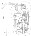
FIG. 1 is a left side view of a tractor. -
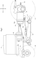
FIG. 2 is a left side view showing an arrangement of an inverter and the like. -
FIG. 3 is a diagram showing a flow of motive power transmission. -
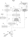
FIG. 4 is a block diagram showing a configuration for charging. -
FIG. 5 is a flowchart of control operations. -
FIG. 6 is a block diagram showing a configuration for charging according to another embodiment. - An embodiment of the present invention will be described based on the drawings. In the following description, unless otherwise stated, the direction of an arrow F and the direction of an arrow B in the drawings will be respectively referred to as "the front side" and "the rear side", and the direction of an arrow L and the direction of an arrow R in the drawings will be respectively referred to as "the left side" and "the right side". Also, the direction of an arrow U and the direction of an arrow D in the drawings will be respectively referred to as "the upper side" and "the lower side".
- The following describes a tractor as an example of an electric work vehicle according to the present invention. As shown in
FIG. 1 , the tractor includes left and rightfront wheels 10, left and rightrear wheels 11, and acover member 12. - The tractor includes a
body frame 2 and adriving section 3. Thebody frame 2 is supported by the left and rightfront wheels 10 and the left and rightrear wheels 11. - The
cover member 12 is disposed in a front portion of the body of the tractor. Thedriving section 3 is behind thecover member 12. In other words, thecover member 12 is in front of thedriving section 3. - The
driving section 3 includes aprotective frame 30, a driver'sseat 31, and asteering wheel 32. An operator can sit in the driver'sseat 31. Accordingly, the operator can get on thedriving section 3. The operator steers the left and rightfront wheels 10 by operating thesteering wheel 32. The operator can perform various driving operations in thedriving section 3. - The tractor includes, as a first battery, a
battery 4 for traveling. Thecover member 12 is configured to be pivotable about an opening and closing axis Q extending in the left-right direction of the body. Accordingly, thecover member 12 is configured to be openable and closable. When thecover member 12 is closed, thebattery 4 for traveling is covered by thecover member 12. - As shown in
FIG. 2 , the tractor includes aninverter 14 and an electric motor M. Thebattery 4 for traveling supplies electric power to theinverter 14. Theinverter 14 converts DC power supplied from thebattery 4 for traveling to AC power, and supplies the AC power to the electric motor M. The electric motor M is driven by the AC power supplied from theinverter 14. - As shown in
FIGS. 2 and3 , the tractor includes a hydraulic continuouslyvariable transmission 15 and atransmission 16. As shown inFIG. 3 , the hydraulic continuouslyvariable transmission 15 includes ahydraulic pump 15a and ahydraulic motor 15b. - The
hydraulic pump 15a is driven by rotational motive power transmitted from the electric motor M. As a result of thehydraulic pump 15a being driven, rotational motive power is output from thehydraulic motor 15b. The hydraulic continuouslyvariable transmission 15 is configured to change the speed of rotational motive power between thehydraulic pump 15a and thehydraulic motor 15b. The hydraulic continuouslyvariable transmission 15 is configured to be capable of changing the transmission ratio in a stepless manner. - The rotational motive power output from the
hydraulic motor 15b is transmitted to thetransmission 16. The speed of the rotational motive power transmitted to thetransmission 16 is changed by a gear transmission mechanism included in thetransmission 16, and the rotational motive power is distributed to the left and rightfront wheels 10 and the left and rightrear wheels 11. Thus, the left and rightfront wheels 10 and the left and rightrear wheels 11 are driven. - As shown in
FIGS. 2 and3 , the tractor also includes amiddle PTO shaft 17 and arear PTO shaft 18. Rotational motive power output from the electric motor M is distributed to thehydraulic pump 15a, themiddle PTO shaft 17, and therear PTO shaft 18. Themiddle PTO shaft 17 and therear PTO shaft 18 are rotated by the distributed rotational motive power. - If a work device is connected to the
middle PTO shaft 17 or therear PTO shaft 18, the work device is driven by rotational motive power transmitted by themiddle PTO shaft 17 or therear PTO shaft 18. For example, in the present embodiment, agrass cutting device 19 is connected to themiddle PTO shaft 17 as shown inFIG. 2 . Thegrass cutting device 19 is driven by rotational motive power transmitted by themiddle PTO shaft 17. - As shown in
FIG. 4 , a configuration related to the control of the electric motor M includes anaccelerator 33, acontrol device 34 configured to control the operation of the electric motor M, and theinverter 14. Theaccelerator 33 is in the vicinity of thesteering wheel 32. Although not shown, theaccelerator 33 includes a pivotable lever and a potentiometer configured to be operated by pivoting the lever. Theaccelerator 33 is connected to thecontrol device 34. Thecontrol device 34 is connected to theinverter 14 via asignal harness 35. Thecontrol device 34 is configured to issue a command to theinverter 14 in response to a command from theaccelerator 33. Theinverter 14 is configured to control the output of the electric motor M by adjusting electric power supplied to the electric motor M from thebattery 4 for traveling, according to the command from thecontrol device 34. - As shown in
FIG. 4 , thebattery 4 for traveling is chargeable by an external power supply device KD. The tractor includes acharging connection section 37 to which apower supply connector 36 of the power supply device KD is connectable. Thecharging connection section 37 is inside thecover member 12 and is configured to be exposed to the outside when thecover member 12 is pivoted open. Thecontrol device 34 is configured to control the operation of the electric motor M and to control the charge state during charging by the power supply device KD. - The
charging connection section 37 is in conformity with commonly used standard specifications. Thebattery 4 for traveling is charged via an electricpower supply line 39 while thepower supply connector 36 is connected to thecharging connection section 37. Thebattery 4 for traveling supplies high-voltage (e.g., several tens to several hundreds of volts) electric power to theinverter 14 and the electric motor M via the electricpower supply line 39. - The
battery 4 for traveling uses, for example, a lithium ion battery and has a configuration in which a large number of small-sized low-voltage unit cells, which are not shown, are stacked, and the exterior of the stack is covered by and enclosed in a housing in a sealed state. - In addition to the
battery 4 for traveling, the tractor includes, as a second battery, abattery 41 for electric components for supplying electric power to thecontrol device 34 and other electric components. Thebattery 41 for electric components supplies low-voltage (12 V) electric power in order to drive the electric components. Thebattery 41 for electric components is charged using electric power supplied from thebattery 4 for traveling via a DC/DC converter (voltage converter) 42. The DC/DC converter 42 is capable of supplying electric power while adjusting the voltage value between thebattery 4 for traveling and thebattery 41 for electrical components. In other words, the DC/DC converter 42 is capable of supplying electric power and charging. - The
driving section 3 includes aswitching operation unit 44 serving as a start command means capable of switching thecontrol device 34 between an operable state and an inactive state. The switchingoperation unit 44 includes aninsertion slot 46 as a securing portion where a portable operation key 45 can be inserted and secured, and a manually-pressable push-button switch 47. Thecontrol device 34 can be switched from the inactive state to the operable state by theswitch 47 being pressed while theoperation key 45 is inserted and secured in theinsertion slot 46. Like an ordinary key for a vehicle, the operation key 45 functions as a key that can be identified only by this specific work vehicle. - The
operation panel 43 includes ameter panel 48 configured to display, for example, traveling conditions of the vehicle body, working conditions, battery information (amount of charge and temperature), and the like. Themeter panel 48 is connected thecontrol device 34, and thecontrol device 34 controls the operation of themeter panel 48. - The
control device 34, theinverter 14, thebattery 4 for traveling, the DC/DC converter 42, themeter panel 48, thecharging connection section 37, and the like are connected via the CAN (Controller Area Network)type signal harness 35 so as to communicate data. Thecontrol device 34 communicates with thecharging connection section 37 via a chargingcommunication harness 49, and information on whether or not thepower supply connector 36 is connected to thecharging connection section 37, information on a charging current required by the work vehicle, and the like are transmitted therebetween. Thecharging connection section 37 and the power supply device KD are also configured such that signals can be communicated therebetween. Furthermore, information on the operation performed on theswitching operation unit 44 is input to thecontrol device 34. - The
control device 34 switches to a charge mode when theoperation key 45 is inserted into theinsertion slot 46 and secured there while thepower supply connector 36 is connected to thecharging connection section 37, and can then charge thebattery 4 for traveling using the power supply device KD. - The
control device 34 switches to the operable state, in which thecontrol device 34 can operate the electric motor M, when theswitch 47 is pressed while theoperation key 45 is inserted and secured in theinsertion slot 46. Also, thecontrol device 34 is configured to switch to the inactive state, in which thecontrol device 34 does not control the operation of the electric motor M, when theoperation key 45 is removed from theinsertion slot 46. - The
control device 34 is configured to execute an interval charging process repeatedly at set time intervals even when thecontrol device 34 is in the inactive state, the interval charging process being a process for controlling the operation of the DC/DC converter 42 to charge thebattery 41 for electric components using electric power supplied from thebattery 4 for traveling. - Hereinafter, control performed by the
control device 34 will be described with reference to the flowchart inFIG. 5 . - When performing work using the work vehicle, the operator inserts and secures the operation key 45 in the
insertion slot 46 of the switchingoperation unit 44 included in theoperation panel 43 in thedriving section 3. At this time, if thepower supply connector 36 of the power supply device KD is connected to thecharging connection section 37, a charging process for charging the battery 1 for traveling is performed (steps #1, #2, and #3). - During the charging process, a charging operation for charging the
battery 4 for traveling using the power supply device KD is started by transmitting necessary information to the power supply device KD via the chargingcommunication harness 49 so as to enable the power supply device KD to supply electric power. Then, thebattery 4 for traveling is charged to a preset charge state, and when it is fully charged, charging is stopped. - When the
switch 47 is pressed while thepower supply connector 36 is not connected to thecharging connection section 37, thecontrol device 34 switches to the operable state in which it can operate the electric motor M (step #04). Then, although not described in detail, thecontrol device 34 controls the operation of the electric motor M based on an operation command given by the operator (step #05). Note that, during the control of the operation of the electric motor M, when theswitch 47 is pressed again, the operation of the electric motor M can be stopped. - After the work using the work vehicle is completed, the operator removes the operation key 45 from the
insertion slot 46, and when theoperation key 45 is removed, thecontrol device 34 switches to the inactive state, in which it does not control the operation of the electric motor M (steps #06 and #07). On switching to the inactive state, thecontrol device 34 switches to an electric power-saving mode in which only the interval charging process, which will be described later, is executable. The electric power-saving mode consumes less electric power than a normal electric power mode in which work is performed by operating the electric motor M. - After switching to the inactive state, the
control device 34 executes the interval charging process repeatedly at set time intervals, the interval charging process is the process for controlling the operation of the DC/DC converter 42 to charge thebattery 41 for electric components using electric power supplied from thebattery 4 for traveling. - More specifically, on switching to the inactive state, the
control device 34 starts timer counting (step #08), and when the time counted by the timer reaches a set period of time (corresponding to each time interval of the set time intervals), thecontrol device 34 controls the operation of the DC/DC converter 42 to charge thebattery 41 for electric components using electric power supplied from thebattery 4 for traveling (steps # 10 and # 11). When charging is completed, thecontrol device 34 resets the timer counted value (step #12) and starts timer counting again. Then, the process fromstep # 08 to step #12 is repeated every set period of time. The process ofsteps # 08, #10, #11, and #12 corresponds to the interval charging process. - When the
operation key 45 is inserted into theinsertion slot 46 and secured there while the interval charging process is being executed, the control returns to the initial state (step #01) (step #09). At that time, thecontrol device 34 returns from the electric power-saving mode to the normal electric power mode. After that, the charging process for charging thebattery 4 for traveling or the control of the operation of the electric motor M can be performed. - The set period of time is (the set time intervals are) set to a length that allows a certain amount of charge to be guaranteed even if no charging occurs within that period of time (within any given time interval). For example, the set period of time (set time intervals) can be set to a length of about one week. In short, it is a length of time during which there is no risk of the
battery 41 for electric components discharging to such a level that the amount of charge remaining in the battery becomes critically low. - By executing the above-described interval charging process, it is possible to prevent the amount of charge in the
battery 41 for electric components from becoming critically low and to suitably charge thebattery 4 for traveling, even if the work vehicle remains unused for a long time. -
- (1) In the above-described embodiment, the
control device 34 is configured to execute the interval charging process and to control the operation of the electric motor M. However, instead of this configuration, a configuration may be adopted in which the electric work vehicle includes, separately from each other, a first control device configured to execute a charging process for charging thebattery 4 for traveling and thebattery 41 for electric components, and a second control device configured to control the operation of the electric motor M, and the first control device executes the interval charging process. - (2) In the above-described embodiment, a configuration in which the operation key 45 can be inserted and secured in the
insertion slot 46 has been described. However, instead of this configuration, a configuration may be adopted in which theoperation key 45 is capable of wireless communication with a receiving portion included in the body of the electric work vehicle, and when theswitch 47 is operated while theoperation key 45 is close to the vehicle body, thecontrol device 34 switches to the operable state. - (3) In the above-described embodiment, the
control device 34 is configured to switch to the electric power-saving mode after theoperation key 45 is removed from theinsertion slot 46. However, instead of this configuration, thecontrol device 34 may be configured to remain in the normal electric power mode even after theoperation key 45 is removed from theinsertion slot 46. - (4) In the above-described embodiment, a configuration has been described in which the electric work vehicle includes the
battery 41 for electric components as the only battery for supplying electric power to thecontrol device 34. However, instead of this configuration, a configuration may be adopted in which, as shown inFIG. 6 , the electric work vehicle includes, in addition to thebattery 41 for electric components, abackup battery 50 that can be used when, for example, thebattery 41 for electric components fails to operate for some reason. - The present invention is applicable not only to a tractor but also to various electric work vehicles such as a rice transplanter, a combine harvester, a construction machine, and the like.
-
- 4: Battery for traveling (first batter)
- 34: Control device
- 41: Battery for electric component (second battery)
- 42: DC/DC converter (voltage converter)
- 43: Operation panel
- 44: Switch (start command means)
- 45: Operation key
- 46: Insertion slot (securing portion)
- KD: Power supply device
- M: Electric motor
Claims (5)
- An electric work vehicle comprising:an electric motor configured to drive a vehicle body to travel;a first battery chargeable by an external power supply device and configured to supply driving electric power to the electric motor;a second battery that is rechargeable and configured to supply electric power to an electric component installed in the vehicle body;a voltage converter configured to supply electric power while adjusting a voltage value between the first battery and the second battery; anda control device to which electric power is supplied from the second battery and configured to control a charge state during charging by the power supply device and to control operation of the voltage converter,wherein the control device is configured to execute an interval charging process repeatedly at set time intervals, the interval charging process being a process for controlling operation of the voltage converter to charge the second battery using electric power supplied from the first battery.
- The electric work vehicle according to claim 1,
wherein the set time intervals are set to a length that allows a certain amount of charge to be guaranteed even if no charging occurs within any given time interval. - The electric work vehicle according to claim 1 or 2,wherein the control device is configured to control operation of the electric motor,the electric work vehicle includes a start command means configured to switch the control device to an operable state in response to the start command means being manually operated in a state in which a portable operation key is close to the vehicle body or a state in which the operation key is secured in a securing portion,the control device is configured to switch to an inactive state in which the control device does not control operation of the electric motor, in response to the operation key being switched to a state in which the operation key is away from the vehicle body or a state in which the operation key is removed from the securing portion, andthe control device is configured to execute the interval charging process even in the inactive state.
- The electric work vehicle according to claim 3,
wherein the control device is configured to operate in an electric power-saving mode in which only the interval charging process is executable, after the operation key is switched to the state in which the operation key is away from the vehicle body or the state in which the operation key is removed from the securing portion. - The electric work vehicle according to any one of claims 1 to 4, comprising:
a backup battery that is separate from the second battery and configured to supply electric power to the control device.
Applications Claiming Priority (2)
| Application Number | Priority Date | Filing Date | Title |
|---|---|---|---|
| JP2022015812A JP7675669B2 (en) | 2022-02-03 | 2022-02-03 | electric work vehicle |
| PCT/JP2022/041914 WO2023149047A1 (en) | 2022-02-03 | 2022-11-10 | Electric work vehicle |
Publications (2)
| Publication Number | Publication Date |
|---|---|
| EP4475377A1 true EP4475377A1 (en) | 2024-12-11 |
| EP4475377A4 EP4475377A4 (en) | 2026-02-11 |
Family
ID=87552156
Family Applications (1)
| Application Number | Title | Priority Date | Filing Date |
|---|---|---|---|
| EP22924952.9A Pending EP4475377A4 (en) | 2022-02-03 | 2022-11-10 | ELECTRIC WORK VEHICLE |
Country Status (4)
| Country | Link |
|---|---|
| US (1) | US20240399927A1 (en) |
| EP (1) | EP4475377A4 (en) |
| JP (1) | JP7675669B2 (en) |
| WO (1) | WO2023149047A1 (en) |
Families Citing this family (1)
| Publication number | Priority date | Publication date | Assignee | Title |
|---|---|---|---|---|
| JP2025030761A (en) * | 2023-08-24 | 2025-03-07 | 井関農機株式会社 | Work vehicles |
Family Cites Families (7)
| Publication number | Priority date | Publication date | Assignee | Title |
|---|---|---|---|---|
| JP2006050779A (en) * | 2004-08-04 | 2006-02-16 | Toyota Motor Corp | Motor driving device |
| JP4466772B2 (en) * | 2008-09-03 | 2010-05-26 | トヨタ自動車株式会社 | Vehicle control device |
| WO2011016134A1 (en) * | 2009-08-07 | 2011-02-10 | トヨタ自動車株式会社 | Power supply system of electrically driven vehicle and control method thereof |
| JP5895472B2 (en) * | 2011-11-22 | 2016-03-30 | 三菱自動車工業株式会社 | Power supply vehicle |
| JP6628616B2 (en) * | 2016-01-19 | 2020-01-15 | 株式会社クボタ | Plug-in hybrid working vehicle |
| JP7191810B2 (en) | 2019-12-23 | 2022-12-19 | 株式会社クボタ | work machine |
| JP7058681B2 (en) * | 2020-03-18 | 2022-04-22 | 本田技研工業株式会社 | Vehicle power system |
-
2022
- 2022-02-03 JP JP2022015812A patent/JP7675669B2/en active Active
- 2022-11-10 WO PCT/JP2022/041914 patent/WO2023149047A1/en not_active Ceased
- 2022-11-10 EP EP22924952.9A patent/EP4475377A4/en active Pending
-
2024
- 2024-08-01 US US18/791,599 patent/US20240399927A1/en active Pending
Also Published As
| Publication number | Publication date |
|---|---|
| WO2023149047A1 (en) | 2023-08-10 |
| JP2023113438A (en) | 2023-08-16 |
| US20240399927A1 (en) | 2024-12-05 |
| JP7675669B2 (en) | 2025-05-13 |
| EP4475377A4 (en) | 2026-02-11 |
Similar Documents
| Publication | Publication Date | Title |
|---|---|---|
| EP1406366B1 (en) | Apparatus for charging battery of mobile communication terminal | |
| US20240399927A1 (en) | Electric work vehicle | |
| US12151584B2 (en) | Working vehicle | |
| EP4475385A1 (en) | Electric work vehicle | |
| JP7825667B2 (en) | electric work vehicle | |
| JP2024120921A5 (en) | ||
| US20240383362A1 (en) | Electric work vehicle | |
| EP1283132A3 (en) | Electronic apparatus, drive mechanism and drive control method for a front panel | |
| US9812741B2 (en) | Method of charging and maintaining lithium ion secondary battery, battery system, vehicle and battery-mounted device | |
| WO2024038627A1 (en) | Electric work vehicle | |
| US12509006B2 (en) | Electrified vehicle with electronic control unit that locks charging lid during program rewriting | |
| JPH1016868A (en) | Electric bicycle | |
| EP4566863A1 (en) | Electric work vehicle | |
| JP7507742B2 (en) | Electric work vehicle | |
| JP7519984B2 (en) | Electric work vehicle | |
| EP4417460A1 (en) | Electric work vehicle | |
| US20240059178A1 (en) | Electric work vehicle | |
| JP7632063B2 (en) | Charging control device | |
| EP4458608A1 (en) | Electric work vehicle | |
| CN114274842A (en) | Electric automobile energy source control method and device, electric automobile and storage medium | |
| CN114248660A (en) | Electric vehicle charging control system capable of setting charging capacity and charging setting device | |
| JP2024078591A (en) | Control device and control method | |
| KR20220117408A (en) | Battery pack and method for managing battery pack | |
| CN116278767A (en) | Whole-vehicle control system of electric automobile and control method thereof |
Legal Events
| Date | Code | Title | Description |
|---|---|---|---|
| STAA | Information on the status of an ep patent application or granted ep patent |
Free format text: STATUS: THE INTERNATIONAL PUBLICATION HAS BEEN MADE |
|
| PUAI | Public reference made under article 153(3) epc to a published international application that has entered the european phase |
Free format text: ORIGINAL CODE: 0009012 |
|
| STAA | Information on the status of an ep patent application or granted ep patent |
Free format text: STATUS: REQUEST FOR EXAMINATION WAS MADE |
|
| 17P | Request for examination filed |
Effective date: 20240808 |
|
| AK | Designated contracting states |
Kind code of ref document: A1 Designated state(s): AL AT BE BG CH CY CZ DE DK EE ES FI FR GB GR HR HU IE IS IT LI LT LU LV MC ME MK MT NL NO PL PT RO RS SE SI SK SM TR |
|
| DAV | Request for validation of the european patent (deleted) | ||
| DAX | Request for extension of the european patent (deleted) | ||
| A4 | Supplementary search report drawn up and despatched |
Effective date: 20260109 |
|
| RIC1 | Information provided on ipc code assigned before grant |
Ipc: H02J 7/00 20060101AFI20260102BHEP Ipc: B60L 1/00 20060101ALI20260102BHEP Ipc: B60L 50/60 20190101ALI20260102BHEP Ipc: B60L 58/12 20190101ALI20260102BHEP Ipc: H01M 10/44 20060101ALI20260102BHEP Ipc: H01M 10/48 20060101ALI20260102BHEP Ipc: H02J 7/04 20060101ALI20260102BHEP Ipc: H02J 7/10 20060101ALI20260102BHEP Ipc: B60L 58/20 20190101ALI20260102BHEP |