EP4475368A1 - Voltage conversion device, and control device for voltage conversion device - Google Patents
Voltage conversion device, and control device for voltage conversion device Download PDFInfo
- Publication number
- EP4475368A1 EP4475368A1 EP23749553.6A EP23749553A EP4475368A1 EP 4475368 A1 EP4475368 A1 EP 4475368A1 EP 23749553 A EP23749553 A EP 23749553A EP 4475368 A1 EP4475368 A1 EP 4475368A1
- Authority
- EP
- European Patent Office
- Prior art keywords
- converter
- voltage
- load
- power
- conversion device
- Prior art date
- Legal status (The legal status is an assumption and is not a legal conclusion. Google has not performed a legal analysis and makes no representation as to the accuracy of the status listed.)
- Pending
Links
Images


Classifications
-
- B—PERFORMING OPERATIONS; TRANSPORTING
- B60—VEHICLES IN GENERAL
- B60L—PROPULSION OF ELECTRICALLY-PROPELLED VEHICLES; SUPPLYING ELECTRIC POWER FOR AUXILIARY EQUIPMENT OF ELECTRICALLY-PROPELLED VEHICLES; ELECTRODYNAMIC BRAKE SYSTEMS FOR VEHICLES IN GENERAL; MAGNETIC SUSPENSION OR LEVITATION FOR VEHICLES; MONITORING OPERATING VARIABLES OF ELECTRICALLY-PROPELLED VEHICLES; ELECTRIC SAFETY DEVICES FOR ELECTRICALLY-PROPELLED VEHICLES
- B60L58/00—Methods or circuit arrangements for monitoring or controlling batteries or fuel cells, specially adapted for electric vehicles
- B60L58/10—Methods or circuit arrangements for monitoring or controlling batteries or fuel cells, specially adapted for electric vehicles for monitoring or controlling batteries
- B60L58/18—Methods or circuit arrangements for monitoring or controlling batteries or fuel cells, specially adapted for electric vehicles for monitoring or controlling batteries of two or more battery modules
- B60L58/20—Methods or circuit arrangements for monitoring or controlling batteries or fuel cells, specially adapted for electric vehicles for monitoring or controlling batteries of two or more battery modules having different nominal voltages
-
- H—ELECTRICITY
- H02—GENERATION; CONVERSION OR DISTRIBUTION OF ELECTRIC POWER
- H02J—ELECTRIC POWER NETWORKS; CIRCUIT ARRANGEMENTS OR SYSTEMS FOR SUPPLYING OR DISTRIBUTING ELECTRIC POWER; SYSTEMS FOR STORING ELECTRIC ENERGY
- H02J1/00—Circuit arrangements for DC mains or DC distribution networks
-
- H—ELECTRICITY
- H02—GENERATION; CONVERSION OR DISTRIBUTION OF ELECTRIC POWER
- H02J—ELECTRIC POWER NETWORKS; CIRCUIT ARRANGEMENTS OR SYSTEMS FOR SUPPLYING OR DISTRIBUTING ELECTRIC POWER; SYSTEMS FOR STORING ELECTRIC ENERGY
- H02J1/00—Circuit arrangements for DC mains or DC distribution networks
- H02J1/08—Three-wire DC power distribution systems; Systems having more than three wires
- H02J1/082—DC supplies with two or more different DC voltage levels
-
- H—ELECTRICITY
- H02—GENERATION; CONVERSION OR DISTRIBUTION OF ELECTRIC POWER
- H02J—ELECTRIC POWER NETWORKS; CIRCUIT ARRANGEMENTS OR SYSTEMS FOR SUPPLYING OR DISTRIBUTING ELECTRIC POWER; SYSTEMS FOR STORING ELECTRIC ENERGY
- H02J7/00—Circuit arrangements for charging or discharging batteries or for supplying loads from batteries
-
- H—ELECTRICITY
- H02—GENERATION; CONVERSION OR DISTRIBUTION OF ELECTRIC POWER
- H02J—ELECTRIC POWER NETWORKS; CIRCUIT ARRANGEMENTS OR SYSTEMS FOR SUPPLYING OR DISTRIBUTING ELECTRIC POWER; SYSTEMS FOR STORING ELECTRIC ENERGY
- H02J7/00—Circuit arrangements for charging or discharging batteries or for supplying loads from batteries
- H02J7/34—Parallel operation in networks using both storage and other DC sources, e.g. providing buffering
- H02J7/342—The other DC source being a battery actively interacting with the first one, i.e. battery to battery charging
-
- H—ELECTRICITY
- H02—GENERATION; CONVERSION OR DISTRIBUTION OF ELECTRIC POWER
- H02J—ELECTRIC POWER NETWORKS; CIRCUIT ARRANGEMENTS OR SYSTEMS FOR SUPPLYING OR DISTRIBUTING ELECTRIC POWER; SYSTEMS FOR STORING ELECTRIC ENERGY
- H02J7/00—Circuit arrangements for charging or discharging batteries or for supplying loads from batteries
- H02J7/865—Battery or charger load switching, e.g. concurrent charging and load supply
-
- H—ELECTRICITY
- H02—GENERATION; CONVERSION OR DISTRIBUTION OF ELECTRIC POWER
- H02M—APPARATUS FOR CONVERSION BETWEEN AC AND AC, BETWEEN AC AND DC, OR BETWEEN DC AND DC, AND FOR USE WITH MAINS OR SIMILAR POWER SUPPLY SYSTEMS; CONVERSION OF DC OR AC INPUT POWER INTO SURGE OUTPUT POWER; CONTROL OR REGULATION THEREOF
- H02M1/00—Details of apparatus for conversion
- H02M1/0067—Converter structures employing plural converter units, other than for parallel operation of the units on a single load
-
- H—ELECTRICITY
- H02—GENERATION; CONVERSION OR DISTRIBUTION OF ELECTRIC POWER
- H02M—APPARATUS FOR CONVERSION BETWEEN AC AND AC, BETWEEN AC AND DC, OR BETWEEN DC AND DC, AND FOR USE WITH MAINS OR SIMILAR POWER SUPPLY SYSTEMS; CONVERSION OF DC OR AC INPUT POWER INTO SURGE OUTPUT POWER; CONTROL OR REGULATION THEREOF
- H02M1/00—Details of apparatus for conversion
- H02M1/32—Means for protecting converters other than automatic disconnection
-
- B—PERFORMING OPERATIONS; TRANSPORTING
- B60—VEHICLES IN GENERAL
- B60L—PROPULSION OF ELECTRICALLY-PROPELLED VEHICLES; SUPPLYING ELECTRIC POWER FOR AUXILIARY EQUIPMENT OF ELECTRICALLY-PROPELLED VEHICLES; ELECTRODYNAMIC BRAKE SYSTEMS FOR VEHICLES IN GENERAL; MAGNETIC SUSPENSION OR LEVITATION FOR VEHICLES; MONITORING OPERATING VARIABLES OF ELECTRICALLY-PROPELLED VEHICLES; ELECTRIC SAFETY DEVICES FOR ELECTRICALLY-PROPELLED VEHICLES
- B60L2210/00—Converter types
- B60L2210/10—DC to DC converters
-
- B—PERFORMING OPERATIONS; TRANSPORTING
- B60—VEHICLES IN GENERAL
- B60L—PROPULSION OF ELECTRICALLY-PROPELLED VEHICLES; SUPPLYING ELECTRIC POWER FOR AUXILIARY EQUIPMENT OF ELECTRICALLY-PROPELLED VEHICLES; ELECTRODYNAMIC BRAKE SYSTEMS FOR VEHICLES IN GENERAL; MAGNETIC SUSPENSION OR LEVITATION FOR VEHICLES; MONITORING OPERATING VARIABLES OF ELECTRICALLY-PROPELLED VEHICLES; ELECTRIC SAFETY DEVICES FOR ELECTRICALLY-PROPELLED VEHICLES
- B60L2210/00—Converter types
- B60L2210/10—DC to DC converters
- B60L2210/12—Buck converters
-
- H—ELECTRICITY
- H02—GENERATION; CONVERSION OR DISTRIBUTION OF ELECTRIC POWER
- H02M—APPARATUS FOR CONVERSION BETWEEN AC AND AC, BETWEEN AC AND DC, OR BETWEEN DC AND DC, AND FOR USE WITH MAINS OR SIMILAR POWER SUPPLY SYSTEMS; CONVERSION OF DC OR AC INPUT POWER INTO SURGE OUTPUT POWER; CONTROL OR REGULATION THEREOF
- H02M3/00—Conversion of DC power input into DC power output
- H02M3/02—Conversion of DC power input into DC power output without intermediate conversion into AC
- H02M3/04—Conversion of DC power input into DC power output without intermediate conversion into AC by static converters
- H02M3/10—Conversion of DC power input into DC power output without intermediate conversion into AC by static converters using discharge tubes with control electrode or semiconductor devices with control electrode
- H02M3/145—Conversion of DC power input into DC power output without intermediate conversion into AC by static converters using discharge tubes with control electrode or semiconductor devices with control electrode using devices of a triode or transistor type requiring continuous application of a control signal
- H02M3/155—Conversion of DC power input into DC power output without intermediate conversion into AC by static converters using discharge tubes with control electrode or semiconductor devices with control electrode using devices of a triode or transistor type requiring continuous application of a control signal using semiconductor devices only
- H02M3/156—Conversion of DC power input into DC power output without intermediate conversion into AC by static converters using discharge tubes with control electrode or semiconductor devices with control electrode using devices of a triode or transistor type requiring continuous application of a control signal using semiconductor devices only with automatic control of output voltage or current, e.g. switching regulators
- H02M3/158—Conversion of DC power input into DC power output without intermediate conversion into AC by static converters using discharge tubes with control electrode or semiconductor devices with control electrode using devices of a triode or transistor type requiring continuous application of a control signal using semiconductor devices only with automatic control of output voltage or current, e.g. switching regulators including plural semiconductor devices as final control devices for a single load
Definitions
- the present disclosure relates to a voltage conversion device and a control device for the voltage conversion device.
- a power supply device that supplies power from a plurality of power supplies to a load
- a power supply device that includes a DC power supply and a large-capacity capacitor, and supplies power from the large-capacity capacitor to the load when an output voltage of the DC power supply falls below a terminal voltage of the large-capacity capacitor
- An object of the power supply device is, when a motor as a load is started up, that is, when large power is temporarily consumed, to stably supply power to the motor in a state where a voltage drop of a power supply output is prevented, and to prevent an increase in size of a power supply by reducing an average supplied power capacity of the power supply.
- Patent Literature 1 JP2000-350380A
- a multi-power supply system including a high voltage (HV) system power supply, a 12V system power supply, and a 48V system power supply
- HV high voltage
- 12V system power supply 12V system power supply
- 48V system power supply 48V system power supply
- an HV-48V converter and an HV-12V converter when the HV-48V converter is designed such that efficiency of the HV-48V converter reaches a peak with respect to steady power of a 48V load, the efficiency of the HV-48V converter may be reduced with respect to peak power of the 48V load.
- the efficiency of the HV-48V converter may be reduced with respect to the steady power of the 48V load.
- the efficiency of the HV-48V converter is reduced.
- redundancy between the 12V system power supply and the 48V system power supply cannot be ensured.
- an object of the present disclosure is to provide, in a power supply system including a plurality of power supplies, a voltage conversion device capable of improving efficiency of a DC/DC converter, ensuring redundancy between the plurality of power supplies, and efficiently absorbing regenerative power, and a control device for the voltage conversion device.
- a voltage conversion device of the present disclosure includes: a first DC/DC converter connected to a storage battery that outputs a first voltage and configured to step down the first voltage input from the storage battery to a second voltage, a first power supply path configured to supply the second voltage from the first DC/DC converter to a first load, a second DC/DC converter connected to the storage battery and configured to step down the first voltage input from the storage battery to a third voltage lower than the second voltage, a second power supply path configured to supply the third voltage from the second DC/DC converter to a second load, a third DC/DC converter connected to the first power supply path and the second power supply path, configured to step down the second voltage input from the first power supply path to the third voltage, and step up the third voltage input from the second power supply path to the second voltage, and a control unit configured to control the first DC/DC converter, the second DC/DC converter, and the third DC/DC converter.
- a control device of a voltage conversion device of the present disclosure is a control device for controlling the voltage conversion device.
- the voltage conversion device includes: a first DC/DC converter connected to a storage battery that outputs a first voltage and configured to step down the first voltage input from the storage battery to a second voltage; a first power supply path configured to supply the second voltage from the first DC/DC converter to a first load; a second DC/DC converter connected to the storage battery and configured to step down the first voltage input from the storage battery to a third voltage lower than the second voltage; a second power supply path configured to supply the third voltage from the second DC/DC converter to a second load; and a third DC/DC converter connected to the first power supply path and the second power supply path, configured to step down the second voltage input from the first power supply path to the third voltage, and step up the third voltage input from the second power supply path to the second voltage.
- Efficiency of the first DC/DC converter with respect to steady power of the first load is set to be higher than efficiency of the first DC/DC converter with respect to peak power of the first load.
- the control device is configured to, when the peak power of the first load is used, drive the first DC/DC converter to step down the first voltage input to the first DC/DC converter to the second voltage, and drive the third DC/DC converter to step up the third voltage input to the third DC/DC converter to the second voltage.
- a control device of a voltage conversion device of the present disclosure is a control device for controlling the voltage conversion device.
- the voltage conversion device includes: a first DC/DC converter connected to a storage battery that outputs a first voltage and configured to step down the first voltage input from the storage battery to a second voltage; a first power supply path configured to supply the second voltage from the first DC/DC converter to a first load; a second DC/DC converter connected to the storage battery and configured to step down the first voltage input from the storage battery to a third voltage lower than the second voltage; a second power supply path configured to supply the third voltage from the second DC/DC converter to a second load; and a third DC/DC converter connected to the first power supply path and the second power supply path, configured to step down the second voltage input from the first power supply path to the third voltage, and step up the third voltage input from the second power supply path to the second voltage.
- Efficiency of the first DC/DC converter with respect to peak power of the first load is set to be higher than efficiency of the first DC/DC converter with respect to steady power of the first load.
- the control device is configured to, when the steady power of the first load is used, drive the first DC/DC converter to step down the first voltage input to the first DC/DC converter to the second voltage, and drive the third DC/DC converter to step down the second voltage input to the third DC/DC converter to the third voltage.
- the efficiency of the DC/DC converter can be improved, the redundancy between the plurality of power supplies can be ensured, and the regenerative power can be efficiently absorbed.
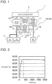
- FIG. 1 is a diagram illustrating a voltage conversion device 10 according to an embodiment of the present disclosure.
- the voltage conversion device 10 illustrated in FIG. 1 is applied to a multi-power supply system 1 of an electric vehicle including a high-voltage power supply (for example, about 400 V to 800 V), a 48V power supply, and a 12V power supply.
- the multi-power supply system 1 includes a high-voltage battery 2, a 12V battery 3, and the voltage conversion device 10, and supplies power to a 48V load 4, a 12V load 5, the 12V battery 3, and a high-voltage motor (not illustrated).
- the multi-power supply system 1 supplies power from the high-voltage battery 2 to the above-mentioned high-voltage motor to drive the high-voltage motor during normal traveling of the electric vehicle.
- the multi-power supply system 1 absorbs the regenerative power of the 48V load 4 by the 12V battery 3 or the high-voltage battery 2.
- the voltage conversion device 10 includes an HV-48V DC/DC converter 11, an HV-12V DC/DC converter 12, a 48V-12V DC/DC converter 13, a first wire harness 14, a second wire harness 15, a third wire harness 16, a fourth wire harness 17, a fifth wire harness 18, and a control device 20.
- the HV-48V DC/DC converter 11 is a bidirectional DC/DC converter.
- a high-voltage side terminal 11A of the HV-48V DC/DC converter 11 is connected to the high-voltage battery 2, and a 48V side terminal 11B of the HV-48V DC/DC converter 11 is connected to the 48V load 4 via the first wire harness 14.
- the HV-48V DC/DC converter 11 steps down a high voltage (HV, for example, 400 V to 800 V) output from the high-voltage battery 2 to 48 V and outputs the 48 V from the 48V-side terminal 11B. Accordingly, the power of 48V is supplied from the HV-48V DC/DC converter 11 to the 48V load 4 through the first wire harness 14. In addition, the regenerative power of the 48V load 4 is input to the HV-48V DC/DC converter 11 through the first wire harness 14. The HV-48V DC/DC converter 11 steps up the 48 V to a high voltage and outputs the high voltage from the high-voltage side terminal 11A to the high-voltage battery 2.
- HV high voltage
- the HV-12V DC/DC converter 12 is a unidirectional DC/DC converter.
- a high-voltage side terminal 12A of the HV-12V DC/DC converter 12 is connected to the high-voltage battery 2
- a 12V side terminal 12B of the HV-12V DC/DC converter 12 is connected to the 12V load 5 via the second wire harness 15.
- the third wire harness 16 branches off from the second wire harness 15, and the 12V side terminal 12B of the HV-12V DC/DC converter 12 and the 12V battery 3 are connected by the second and third wire harnesses 15 and 16.
- the HV-12V DC/DC converter 12 steps down the high voltage output from the high-voltage battery 2 to 12 V and outputs the 12 V from the 12V side terminal 12B. Accordingly, the power of 12 V is supplied from the HV-12V DC/DC converter 12 to the 12V load 5 through the second wire harness 15. In addition, the power of 12 V is supplied from the HV-12V DC/DC converter 12 to the 12V battery 3 through the second and third wire harnesses 15 and 16.
- the fourth wire harness 17 branches off from the first wire harness 14 and is connected to a 48V side terminal 13A of the 48V-12V DC/DC converter 13.
- the fifth wire harness 18 branches off from the second wire harness 15 and is connected to a 12V side terminal 13B of the 48V-12V DC/DC converter 13.
- the 48V-12V DC/DC converter 13 is a bidirectional DC/DC converter.
- the 48V-12V DC/DC converter 13 steps down the 48 V output from the HV-48V DC/DC converter 11 to 12 V and outputs the 12 V from the 12V side terminal 13B.
- the voltage of 12 V is supplied from the 48V-12V DC/DC converter 13 to the 12V load 5 through the fifth and second wire harnesses 18 and 15.
- the voltage of 12 V is supplied from the 48V-12V DC/DC converter 13 to the 12V battery 3 through the fifth, second, and third wire harnesses 18, 15, and 16.
- the regenerative power of the 48V load 4 is input to the 48V-12V DC/DC converter 13 through the first and fourth wire harnesses 14 and 17.
- the 48V-12V DC/DC converter 13 steps down the 48 V to 12 V and outputs the 12 V from the 12V side terminal 13B. Accordingly, the voltage of 12 V is supplied from the 48V-12V DC/DC converter 13 to the 12V load 5 through the fifth and second wire harnesses 18 and 15. In addition, the voltage of 12 V is supplied from the 48V-12V DC/DC converter 13 to the 12V battery 3 through the fifth, second, and third wire harnesses 18, 15, and 16.
- the 48V-12V DC/DC converter 13 steps up the 12 V output from the 12V battery 3 to 48 V and outputs the 48 V from the 48V side terminal 13A. Accordingly, the voltage of 48 V is supplied from the 48V-12V DC/DC converter 13 to the 48V load 4 through the fourth and first wire harnesses 17 and 14.
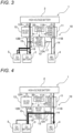
- FIG. 2 is a graph illustrating a relation between power [W] and efficiency [%] of the HV-48V DC/DC converter 11 illustrated in FIG. 1 .
- the HV-48V DC/DC converter 11 is designed such that efficiency of the HV-48V DC/DC converter 11 reaches a peak when an input power is 300 W.
- the power of 300 W is steady power of the 48V load 4.
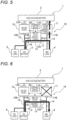
- FIGS. 3 to 7 are diagrams illustrating operations of the voltage conversion device 10 illustrated in FIG. 1 .
- a magnitude of supplied power is identified by a thickness of an arrow.
- FIG. 3 is a diagram illustrating an operation (steady operation) of the voltage conversion device 10 when the steady power of the 48V load 4 is used.
- the control device 20 drives the HV-48V DC/DC converter 11 to step down the high voltage output from the high-voltage battery 2 to 48 V
- the control device 20 drives the HV-12V DC/DC converter 12 to step down the high voltage output from the high-voltage battery 2 to 12 V
- the control device 20 stops the 48V-12V DC/DC converter 13.
- the high voltage output from the high-voltage battery 2 is stepped down to 48 V by the HV-48V DC/DC converter 11 and supplied to the 48V load 4.
- the efficiency of the HV-48V DC/DC converter 11 reaches a peak, and high-efficiency voltage conversion of the HV-48V DC/DC converter 11 is realized.
- the high voltage output from the high-voltage battery 2 is stepped down to 12 V by the HV-12V DC/DC converter 12 and supplied to the 12V load 5. Further, when the steady power of the 48V load 4 is used, the high voltage output from the high-voltage battery 2 is stepped down to 12 V by the HV-12V DC/DC converter 12 and supplied to the 12V battery 3.
- FIG. 4 is a diagram illustrating an operation of the voltage conversion device 10 when peak power of the 48V load 4 is used.
- the control device 20 drives the HV-48V DC/DC converter 11 to step down the high voltage output from the high-voltage battery 2 to 48 V
- the control device 20 drives the 48V-12V DC/DC converter 13 to step up the 12 V output from the 12V battery 3 to 48 V
- the control device 20 drives the HV-12V DC/DC converter 12 to step down the high voltage output from the high-voltage battery 2 to 12 V as necessary.
- the high voltage output from the high-voltage battery 2 is stepped down to 48 V by the HV-48V DC/DC converter 11 and supplied to the 48V load 4.
- the 12 V output from the 12V battery 3 is stepped up to 48 V by the 48V-12V DC/DC converter 13 and supplied to the 48V load 4.
- the high voltage output from the high-voltage battery 2 is stepped down to 12 V by the HV-12V DC/DC converter 12 and supplied to the 12V battery 3 as necessary.
- the HV-48V DC/DC converter 11 is designed such that the efficiency of the HV-48V DC/DC converter 11 reaches a peak when the input power is the steady power of the 48V load 4. Therefore, when the input power of the HV-48V DC/DC converter 11 is the peak power of the 48V load 4, the efficiency of the HV-48V DC/DC converter 11 becomes lower than the peak. Therefore, in the voltage conversion device 10 of the present embodiment, the 48V-12V DC/DC converter 13 is driven to step up the 12 V output from the 12V battery 3 to 48 V and supply the 48 V to the 48V load 4, thereby assisting the supply of the peak power to the 48V load 4.
- FIG. 5 is a diagram illustrating an operation of the voltage conversion device 10 when regenerative power of the 48V load 4 is generated.
- the control device 20 drives the 48V-12V DC/DC converter 13 to step down the 48 V output from the 48V load 4 to 12 V
- the control device 20 drives the HV-48V DC/DC converter 11 to step up the 48 V output from the 48V load 4 to a high voltage as necessary, for example, at the time of absorption of the peak power.
- the 48 V output from the 48V load 4 is stepped down by the 48V-12V DC/DC converter 13 and supplied to the 12V battery 3.
- the 48 V output from the 48V load 4 is stepped up by the HV-48V DC/DC converter 11 and supplied to the high-voltage battery 2.
- FIG. 6 is a diagram illustrating an operation of the voltage conversion device 10 when the HV-48V DC/DC converter 11 fails. As illustrated in FIG. 6 , when the HV-48V DC/DC converter 11 fails, the control device 20 drives the 48V-12V DC/DC converter 13 to step up the 12 V output from the 12V battery 3 to 48 V
- the HV-48V DC/DC converter 11 fails, the 12 V output from the 12V battery 3 is stepped up by the 48V-12V DC/DC converter 13 and supplied to the 48V load 4. That is, when the HV-48V DC/DC converter 11 fails, a voltage conversion function of the HV-48VDC/DC converter 11 is complemented by the 48V-12VDC/DC converter 13.
- FIG. 7 is a diagram illustrating an operation of the voltage conversion device 10 when the 48V-12V DC/DC converter 13 fails. As illustrated in FIG. 7 , when the 48V-12V DC/DC converter 13 fails, the control device 20 drives the HV-48V DC/DC converter 11 to step down the high voltage output from the high-voltage battery 2 to 48 V
- the 48V-12V DC/DC converter 13 fails, the high voltage output from the high-voltage battery 2 is stepped down by the HV-48V DC/DC converter 11 and supplied to the 48V load 4. That is, when the 48V-12V DC/DC converter 13 fails, a voltage conversion function of the 48V-12V DC/DC converter 13 is complemented by the HV-48V DC/DC converter 11.
- the 48V-12V DC/DC converter 13 that converts 48 V and 12 V into two directions is provided between the 48V system power supply and the 12V system power supply so as to connect the 48V system power supply and the 12V system power supply. Accordingly, the efficiency of the HV-48V DC/DC converter 11 can be improved, the redundancy between the 48V system power supply and the 12V system power supply can be ensured, and the regenerative power of the 48V load 4 can be efficiently absorbed.
- the efficiency of the HV-48V DC/DC converter 11 is set to reach a peak when the input power is the steady power of the 48V load 4 from the viewpoint of maximally preventing a loss in the voltage conversion of the HV-48V DC/DC converter 11. Accordingly, when the steady power of the 48V load 4 is used, the input power of the HV-48V DC/DC converter 11 is set to the steady power of the 48V load 4, and the HV-48V DC/DC converter 11 can be driven with high efficiency.
- the 48V-12V DC/DC converter 13 is driven to step up the 12 V output from the 12V battery 3 to 48 V and supply the 48 V to the 48V load 4, thereby assisting the supply of the peak power to the 48V load 4. Accordingly, even when the peak power of the 48V load 4 is used, the input power of the HV-48V DC/DC converter 11 is set to the steady power of the 48V load 4, and the HV-48V DC/DC converter 11 can be driven with high efficiency.
- the voltage conversion function of the HV-48V DC/DC converter 11 can be complemented by driving the 48V-12V DC/DC converter 13 to supply power from the 12V battery 3 to the 48V load 4.
- the voltage conversion function of the 48V-12V DC/DC converter 13 can be complemented by driving the HV-48V DC/DC converter 11 to supply power from the high-voltage battery 2 to the 48V load 4.
- the regenerative power of the 48V load 4 can be regenerated in the 12V battery 3 by driving the 48V-12V DC/DC converter 13. Accordingly, an opportunity for power conversion in a reverse direction of the HV-48V DC/DC converter 11 can be reduced, and a reduction in efficiency of the HV-48V DC/DC converter 11 can be prevented.
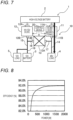
- FIG. 8 is a graph illustrating a relation between power [W] and efficiency [%] of the HV-48V DC/DC converter 11 in a voltage conversion device 10A (see FIG. 1 ) according to another embodiment of the present disclosure.
- the HV-48V DC/DC converter 11 is designed such that the efficiency of the HV-48V DC/DC converter 11 reaches a peak when the input power is 2,000 W.
- the power of 2,000 W is the peak power of the 48V load 4.
- the input power of the HV-48V DC/DC 11 is 1,200 W.
- the efficiency of the HV-48V DC/DC converter 11 is lower than that when the input power is 2,000 W, and is higher than that when the input power is 300 W.
- FIGS. 9 to 13 are diagrams illustrating operations of the voltage conversion device 10A of the present embodiment.
- a magnitude of supplied power is identified by a thickness of an arrow.
- FIG. 9 is a diagram illustrating an operation of the voltage conversion device 10A when the steady power of the 48V load 4 is used.
- the control device 20 drives the HV-48V DC/DC converter 11 to step down the high voltage output from the high-voltage battery 2 to 48 V
- the control device 20 drives the 48V-12V DC/DC converter 13 to step down the 48 V output from the HV-48V DC/DC converter 11 to 12 V
- the control device 20 drives the HV-12V DC/DC converter 12 to step down the high voltage output from the high-voltage battery 2 to 12 V
- the high voltage output from the high-voltage battery 2 is stepped down to 48 V by the HV-48V DC/DC converter 11 and supplied to the 48V load 4.
- the 48 V output from the HV-48V DC/DC converter 11 is stepped down to 12 V by the 48V-12V DC/DC converter 13 and supplied to the 12V battery 3.
- the high voltage output from the high-voltage battery 2 is stepped down to 12 V by the HV-12V DC/DC converter 12 and supplied to the 12V battery 3 and the 12V load 5.
- the efficiency of the HV-48V DC/DC converter 11 is lower than that when the input power is 2,000 W, but is higher than that when the input power is 300 W. Accordingly, the efficiency of the HV-48V DC/DC converter 11 does not reach the peak, but becomes high, and high-efficiency voltage conversion of the HV-48V DC/DC converter 11 is realized.
- FIG. 10 is a diagram illustrating an operation of the voltage conversion device 10A when the peak power of the 48V load 4 is used.
- the control device 20 drives the HV-48V DC/DC converter 11 to step down the high voltage output from the high-voltage battery 2 to 48 V
- the control device 20 drives the 48V-12V DC/DC converter 13 to step up the 12 V output from the 12V battery 3 to 48 V
- the high voltage output from the high-voltage battery 2 is stepped down to 48 V by the HV-48V DC/DC converter 11 and supplied to the 48V load 4.
- the input power of the HV-48V DC/DC converter 11 is the peak power of the 48V load 4, and high-efficiency voltage conversion of the HV-48V DC/DC converter 11 is realized.
- the 12 V output from the 12V battery 3 is stepped up to 48 V by the 48V-12V DC/DC converter 13 and supplied to the 48V load 4 (indicated by a broken line). Accordingly, the supply of the peak power to the 48V load 4 is assisted.
- FIG. 11 is a diagram illustrating an operation of the voltage conversion device 10A when the regenerative power of the 48V load 4 is generated.
- the control device 20 drives the 48V-12V DC/DC converter 13 to step down the 48 V output from the 48V load 4 to 12 V
- the control device 20 drives the HV-48V DC/DC converter 11 to step up the 48 V output from the 48V load 4 to a high voltage as necessary, for example, at the time of absorption of the peak power.
- the regenerative power of 48 V of the 48V load 4 is stepped down by the 48V-12V DC/DC converter 13 and supplied to the 12V battery 3.
- the regenerative power of 48 V of the 48V load 4 is stepped up to a high voltage by the HV-48V DC/DC converter 11 and supplied to the high-voltage battery 2 (indicated by a broken line).
- FIG. 12 is a diagram illustrating an operation of the voltage conversion device 10A when the HV-48V DC/DC converter 11 fails. As illustrated in FIG. 12 , when the HV-48V DC/DC converter 11 fails, the control device 20 drives the 48V-12V DC/DC converter 13 to step up the 12 V output from the 12V battery 3 to 48 V
- the HV-48V DC/DC converter 11 fails, the 12 V output from the 12V battery 3 is stepped up by the 48V-12V DC/DC converter 13 and supplied to the 48V load 4. That is, when the HV-48V DC/DC converter 11 fails, a voltage conversion function of the HV-48VDC/DC converter 11 is complemented by the 48V-12VDC/DC converter 13.
- FIG. 13 is a diagram illustrating an operation of the voltage conversion device 10A when the 48V-12V DC/DC converter 13 fails. As illustrated in FIG. 13 , when the 48V-12V DC/DC converter 13 fails, the control device 20 drives the HV-48V DC/DC converter 11 to step down the high voltage output from the high-voltage battery 2 to 48 V
- the 48V-12V DC/DC converter 13 fails, the high voltage output from the high-voltage battery 2 is stepped down by the HV-48V DC/DC converter 11 and supplied to the 48V load 4. That is, when the 48V-12V DC/DC converter 13 fails, a voltage conversion function of the 48V-12V DC/DC converter 13 is complemented by the HV-48V DC/DC converter 11.
- the efficiency of the HV-48V DC/DC converter 11 is set to reach a peak when the input power is the peak power of the 48V load 4 from the viewpoint of maximally increasing the efficiency of the HV-48V DC/DC converter 11 when the peak power of the 48V load 4 is used. Accordingly, when the peak power of the 48V load 4 is used, the input power of the HV-48V DC/DC converter 11 is set to the peak power, and the HV-48V DC/DC converter 11 can be driven with high efficiency. On the other hand, when the steady power of the 48V load 4 is used, the 48V-12V DC/DC converter 13 is driven to supply power to the 12V load 5 or the 12V battery 3.
- the input power of the HV-48V DC/DC converter 11 is set to intermediate power between the steady power and the peak power, and the HV-48V DC/DC converter 11 can be driven with high efficiency.
- conversion power of the HV-12V DC/DC converter 12 can be reduced, which contributes to achieving an increase in efficiency of the HV-12V DC/DC converter 12.
- FIG. 14 is a diagram illustrating a voltage conversion device 10B according to another embodiment of the present disclosure. As illustrated in FIG. 14 , the voltage conversion device 10B of the present embodiment is different from the voltage conversion devices 10 and 10A of the above-mentioned embodiments in that the 12V battery is not provided.
- FIG. 15 is a graph illustrating a relation between power [W] and efficiency [%] of the HV-48V DC/DC converter 11 in the voltage conversion device 10B illustrated in FIG. 14 .
- the HV-48V DC/DC converter 11 is designed such that the efficiency of the HV-48V DC/DC converter 11 reaches a peak when the input power is 1,200 W.
- the steady power of the 48V load 4 is 300 W, and the peak power of the 48V load 4 is 2,000 W.
- FIGS. 16 to 21 are diagrams illustrating operations of the voltage conversion device 10B of the present embodiment.
- a magnitude of supplied power is identified by a thickness of an arrow.
- FIG. 16 is a diagram illustrating an operation of the voltage conversion device 10B when the steady power of the 48V load 4 is used.
- the control device 20 drives the HV-48V DC/DC converter 11 to step down the high voltage output from the high-voltage battery 2 to 48 V
- the control device 20 drives the HV-12V DC/DC converter 12 to step down the high voltage output from the high-voltage battery 2 to 12 V
- the control device 20 drives the 48V-12V DC/DC converter 13 to step down the 48 V output from the HV-48V DC/DC converter 11 to 12 V
- the high voltage output from the high-voltage battery 2 is stepped down to 48 V by the HV-48V DC/DC converter 11 and supplied to the 48V load 4.
- the high voltage output from the high-voltage battery 2 is stepped down to 12 V by the HV-12V DC/DC converter 12 and supplied to the 12V load 5.
- the 48V load 4 is a low load
- the 48 V output from the HV-48V DC/DC converter 11 is stepped down to 12 V by the 48V-12V DC/DC converter 13 and supplied to the 12V load 5.
- the 48V load 4 is a low load
- FIG. 17 is a diagram illustrating an operation of the voltage conversion device 10B when the peak power of the 48V load 4 is used.
- the control device 20 drives the HV-48V DC/DC converter 11 to step down the high voltage output from the high-voltage battery 2 to 48 V
- the control device 20 drives the HV-12V DC/DC converter 12 to step down the high voltage output from the high-voltage battery 2 to 12 V
- the control device 20 drives the 48V-12V DC/DC converter 13 to step up the 12 V output from the HV-12V DC/DC converter 12 to 48 V
- the high voltage output from the high-voltage battery 2 is stepped down to 48 V by the HV-48V DC/DC converter 11 and supplied to the 48V load 4.
- the high voltage output from the high-voltage battery 2 is stepped down to 12 V by the HV-12V DC/DC converter 12 and supplied to the 12V load 5.
- the 12 V output from the HV-12V DC/DC converter 12 is stepped up to 48 V by the 48V-12V DC/DC converter 13 and supplied to the 48V load 4 (indicated by a broken line). Accordingly, the supply of the peak power to the 48V load 4 is assisted.
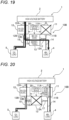
- FIG. 18 is a diagram illustrating an operation of the voltage conversion device 10B when the regenerative power of the 48V load 4 is generated.
- the control device 20 drives the 48V-12V DC/DC converter 13 to step down the 48 V output from the 48V load 4 to 12 V
- the control device 20 drives the HV-48V DC/DC converter 11 to step up the 48 V output from the 48V load 4 to a high voltage as necessary, for example, at the time of absorption of the peak power of the 48V load 4.
- the regenerative power of 48 V of the 48V load 4 is stepped down to 12 V by the 48V-12V DC/DC converter 13 and supplied to the 12V load 5.
- the 48 V output from the 48V load 4 is stepped up to a high voltage by the HV-48V DC/DC converter 11 and supplied to the high-voltage battery 2.
- FIG. 19 is a diagram illustrating an operation of the voltage conversion device 10B when the HV-48V DC/DC converter 11 fails. As illustrated in FIG. 19 , when the HV-48V DC/DC converter 11 fails, the control device 20 drives the HV-12V DC/DC converter 12 to step down the high voltage output from the high-voltage battery 2 to 12 V, and drives the 48V-12V DC/DC converter 13 to step up the 12 V output from the HV-12V DC/DC converter 12 to 48 V
- the HV-48V DC/DC converter 11 fails, the high voltage output from the high-voltage battery 2 is supplied to the 48V load 4 through a step-down to 12 V by the HV-12VDC/DC converter 12 and a step-up to 48 V by the 48V-12VDC/DC converter 13. That is, when the HV-48V DC/DC converter 11 fails, a voltage conversion function of the HV-48V DC/DC converter 11 is complemented by the 48V-12V DC/DC converter 13.
- FIG. 20 is a diagram illustrating an operation of the voltage conversion device 10B when the 48V-12V DC/DC converter 13 fails.
- the control device 20 drives the HV-48V DC/DC converter 11 to step down the high voltage output from the high-voltage battery 2 to 48 V
- the control device 20 drives the HV-12V DC/DC converter 12 to step down the high voltage output from the high-voltage battery 2 to 12 V
- the high voltage output from the high-voltage battery 2 is stepped down to 48 V by the HV-48V DC/DC converter 11 and supplied to the 48V load 4.
- the high voltage output from the high-voltage battery 2 is stepped down to 12 V by the HV-12V DC/DC converter 12 and supplied to the 12V load 5. That is, when the 48V-12V DC/DC converter 13 fails, the voltage conversion function of the 48V-12V DC/DC converter 13 is complemented by the HV-48V DC/DC converter 11 and the HV-12V DC/DC converter 12.
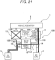
- FIG. 21 is a diagram illustrating an operation of the voltage conversion device 10B when the HV-12V DC/DC converter 12 fails.
- the control device 20 drives the HV-48V DC/DC converter 11 to step down the high voltage output from the high-voltage battery 2 to 48 V, and drives the 48V-12V DC/DC converter 13 to step down the 48 V output from the HV-48V DC/DC converter 11 to 12 V
- the HV-12V DC/DC converter 12 fails, the high voltage output from the high-voltage battery 2 is supplied to the 12V load 5 through a step-down to 48 V by the HV-48V DC/DC converter 11 and a step-down to 12 V by the 48V-12V DC/DC converter 13. That is, when the HV-12V DC/DC converter 12 fails, a voltage conversion function of the HV-12V DC/DC converter 12 is complemented by the HV-48V DC/DC converter 11 and the 48V-12V DC/DC converter 13.
- the efficiency of the HV-48V DC/DC converter 11 is set to reach a peak when the input power is the intermediate power between the steady power and the peak power.
- the 48V-12V DC/DC converter 13 is driven to supply power to the 12V load 5.
- the input power of the HV-48V DC/DC converter 11 is set to the intermediate power between the steady power and the peak power, and the HV-48V DC/DC converter 11 can be driven with high efficiency.
- conversion power of the HV-12V DC/DC converter 12 can be reduced, which contributes to achieving an increase in efficiency of the HV-12V DC/DC converter 12.
- the efficiency of the HV-48V DC/DC converter 11 it is not essential to set the efficiency of the HV-48V DC/DC converter 11 to the peak when the input power is the steady power of the 48V load 4.
- the efficiency of the HV-48V DC/DC converter 11 when the input power is the steady power of the 48V load 4 may be set higher than the efficiency of the HV-48V DC/DC converter 11 when the input power is the peak power of the 48V load 4.
- the efficiency of the HV-48V DC/DC converter 11 when the input power is the peak power of the 48V load 4 may be set higher than the efficiency of the HV-48V DC/DC converter 11 when the input power is the steady power of the 48V load 4.
Landscapes
- Engineering & Computer Science (AREA)
- Power Engineering (AREA)
- Life Sciences & Earth Sciences (AREA)
- Sustainable Development (AREA)
- Sustainable Energy (AREA)
- Transportation (AREA)
- Mechanical Engineering (AREA)
- Charge And Discharge Circuits For Batteries Or The Like (AREA)
- Dc-Dc Converters (AREA)
- Direct Current Feeding And Distribution (AREA)
Abstract
Description
- The present disclosure relates to a voltage conversion device and a control device for the voltage conversion device.
- As a power supply device that supplies power from a plurality of power supplies to a load, there is known a power supply device that includes a DC power supply and a large-capacity capacitor, and supplies power from the large-capacity capacitor to the load when an output voltage of the DC power supply falls below a terminal voltage of the large-capacity capacitor (for example, see Patent Literature 1). An object of the power supply device is, when a motor as a load is started up, that is, when large power is temporarily consumed, to stably supply power to the motor in a state where a voltage drop of a power supply output is prevented, and to prevent an increase in size of a power supply by reducing an average supplied power capacity of the power supply.
- Patent Literature 1:
JP2000-350380A - In a multi-power supply system including a high voltage (HV) system power supply, a 12V system power supply, and a 48V system power supply, it is conceivable to use an HV-48V converter and an HV-12V converter. In the multi-power supply system, when the HV-48V converter is designed such that efficiency of the HV-48V converter reaches a peak with respect to steady power of a 48V load, the efficiency of the HV-48V converter may be reduced with respect to peak power of the 48V load. On the other hand, when the HV-48V converter is designed such that the efficiency of the HV-48V converter reaches a peak with respect to the peak power of the 48V load, the efficiency of the HV-48V converter may be reduced with respect to the steady power of the 48V load.
- In addition, in the above-mentioned multi-power supply system, in a case where the HV-48V converter is made bidirectional in order to cause an HV system power supply to regenerate regenerative power of the 48V load, the efficiency of the HV-48V converter is reduced. Further, in the above-mentioned multi-power supply system, in a case where a failure occurs in one of the HV-48V converter and the HV-12V converter, redundancy between the 12V system power supply and the 48V system power supply cannot be ensured.
- In view of the above-mentioned circumstances, an object of the present disclosure is to provide, in a power supply system including a plurality of power supplies, a voltage conversion device capable of improving efficiency of a DC/DC converter, ensuring redundancy between the plurality of power supplies, and efficiently absorbing regenerative power, and a control device for the voltage conversion device.
- A voltage conversion device of the present disclosure includes: a first DC/DC converter connected to a storage battery that outputs a first voltage and configured to step down the first voltage input from the storage battery to a second voltage, a first power supply path configured to supply the second voltage from the first DC/DC converter to a first load, a second DC/DC converter connected to the storage battery and configured to step down the first voltage input from the storage battery to a third voltage lower than the second voltage, a second power supply path configured to supply the third voltage from the second DC/DC converter to a second load, a third DC/DC converter connected to the first power supply path and the second power supply path, configured to step down the second voltage input from the first power supply path to the third voltage, and step up the third voltage input from the second power supply path to the second voltage, and a control unit configured to control the first DC/DC converter, the second DC/DC converter, and the third DC/DC converter.
- A control device of a voltage conversion device of the present disclosure is a control device for controlling the voltage conversion device. The voltage conversion device includes: a first DC/DC converter connected to a storage battery that outputs a first voltage and configured to step down the first voltage input from the storage battery to a second voltage; a first power supply path configured to supply the second voltage from the first DC/DC converter to a first load; a second DC/DC converter connected to the storage battery and configured to step down the first voltage input from the storage battery to a third voltage lower than the second voltage; a second power supply path configured to supply the third voltage from the second DC/DC converter to a second load; and a third DC/DC converter connected to the first power supply path and the second power supply path, configured to step down the second voltage input from the first power supply path to the third voltage, and step up the third voltage input from the second power supply path to the second voltage. Efficiency of the first DC/DC converter with respect to steady power of the first load is set to be higher than efficiency of the first DC/DC converter with respect to peak power of the first load. The control device is configured to, when the peak power of the first load is used, drive the first DC/DC converter to step down the first voltage input to the first DC/DC converter to the second voltage, and drive the third DC/DC converter to step up the third voltage input to the third DC/DC converter to the second voltage.
- A control device of a voltage conversion device of the present disclosure is a control device for controlling the voltage conversion device. The voltage conversion device includes: a first DC/DC converter connected to a storage battery that outputs a first voltage and configured to step down the first voltage input from the storage battery to a second voltage; a first power supply path configured to supply the second voltage from the first DC/DC converter to a first load; a second DC/DC converter connected to the storage battery and configured to step down the first voltage input from the storage battery to a third voltage lower than the second voltage; a second power supply path configured to supply the third voltage from the second DC/DC converter to a second load; and a third DC/DC converter connected to the first power supply path and the second power supply path, configured to step down the second voltage input from the first power supply path to the third voltage, and step up the third voltage input from the second power supply path to the second voltage. Efficiency of the first DC/DC converter with respect to peak power of the first load is set to be higher than efficiency of the first DC/DC converter with respect to steady power of the first load. The control device is configured to, when the steady power of the first load is used, drive the first DC/DC converter to step down the first voltage input to the first DC/DC converter to the second voltage, and drive the third DC/DC converter to step down the second voltage input to the third DC/DC converter to the third voltage.
- According to the present disclosure, in the power supply system including a plurality of power supplies, the efficiency of the DC/DC converter can be improved, the redundancy between the plurality of power supplies can be ensured, and the regenerative power can be efficiently absorbed.
-
- [
FIG. 1] FIG. 1 is a diagram illustrating a voltage conversion device according to an embodiment of the present disclosure. - [
FIG. 2] FIG. 2 is a graph illustrating a relation between power [W] and efficiency [%] of an HV-48V DC/DC converter illustrated inFIG. 1 . - [
FIG. 3] FIG. 3 is a diagram illustrating an operation of the voltage conversion device when steady power of a 48V load is used. - [
FIG. 4] FIG. 4 is a diagram illustrating an operation of the voltage conversion device when peak power of the 48V load is used. - [
FIG. 5] FIG. 5 is a diagram illustrating an operation of the voltage conversion device when regenerative power of the 48V load is generated. - [
FIG. 6] FIG. 6 is a diagram illustrating an operation of the voltage conversion device when the HV-48V DC/DC converter fails. - [
FIG. 7] FIG. 7 is a diagram illustrating an operation of the voltage conversion device when a 48V-12V DC/DC converter fails. - [
FIG. 8] FIG. 8 is a graph illustrating a relation between power [W] and efficiency [%] of an HV-48V DC/DC converter in a voltage conversion device according to another embodiment of the present disclosure. - [
FIG. 9] FIG. 9 is a diagram illustrating an operation of the voltage conversion device when steady power of a 48V load is used. - [
FIG. 10] FIG. 10 is a diagram illustrating an operation of the voltage conversion device when peak power of the 48V load is used. - [
FIG. 11] FIG. 11 is a diagram illustrating an operation of the voltage conversion device when regenerative power of the 48V load is generated. - [
FIG. 12] FIG. 12 is a diagram illustrating an operation of the voltage conversion device when the HV-48V DC/DC converter fails. - [
FIG. 13] FIG. 13 is a diagram illustrating an operation of the voltage conversion device when a 48V-12V DC/DC converter fails. - [
FIG. 14] FIG. 14 is a diagram illustrating a voltage conversion device according to another embodiment of the present disclosure. - [
FIG. 15] FIG. 15 is a graph illustrating a relation between power [W] and efficiency [%] of an HV-48V DC/DC converter in the voltage conversion device illustrated inFIG. 14 . - [
FIG. 16] FIG. 16 is a diagram illustrating an operation of the voltage conversion device when steady power of a 48V load is used. - [
FIG. 17] FIG. 17 is a diagram illustrating an operation of the voltage conversion device when peak power of the 48V load is used. - [
FIG. 18] FIG. 18 is a diagram illustrating an operation of the voltage conversion device when regenerative power of the 48V load is generated. - [
FIG. 19] FIG. 19 is a diagram illustrating an operation of the voltage conversion device when the HV-48V DC/DC converter fails. - [
FIG. 20] FIG. 20 is a diagram illustrating an operation of the voltage conversion device when a 48V-12V DC/DC converter fails. - [
FIG. 21] FIG. 21 is a diagram illustrating an operation of the voltage conversion device when an HV-12V DC/DC converter fails. - Hereinafter, the present disclosure will be described with reference to a preferred embodiment. The present disclosure is not limited to the following embodiment, and can be appropriately modified without departing from the gist of the present disclosure. In the following embodiment, a part of configurations may be not described or shown in the drawings, and regarding details of the omitted techniques, publicly known or well-known techniques will be appropriately applied as long as there is no contradiction with the contents to be described below.
-
FIG. 1 is a diagram illustrating avoltage conversion device 10 according to an embodiment of the present disclosure. Thevoltage conversion device 10 illustrated inFIG. 1 is applied to amulti-power supply system 1 of an electric vehicle including a high-voltage power supply (for example, about 400 V to 800 V), a 48V power supply, and a 12V power supply. Themulti-power supply system 1 includes a high-voltage battery 2, a12V battery 3, and thevoltage conversion device 10, and supplies power to a48V load 4, a12V load 5, the12V battery 3, and a high-voltage motor (not illustrated). - The
multi-power supply system 1 supplies power from the high-voltage battery 2 to the above-mentioned high-voltage motor to drive the high-voltage motor during normal traveling of the electric vehicle. In addition, themulti-power supply system 1 absorbs the regenerative power of the48V load 4 by the12V battery 3 or the high-voltage battery 2. - The
voltage conversion device 10 includes an HV-48V DC/DC converter 11, an HV-12V DC/DC converter 12, a 48V-12V DC/DC converter 13, afirst wire harness 14, asecond wire harness 15, athird wire harness 16, afourth wire harness 17, afifth wire harness 18, and acontrol device 20. - The HV-48V DC/
DC converter 11 is a bidirectional DC/DC converter. A high-voltage side terminal 11A of the HV-48V DC/DC converter 11 is connected to the high-voltage battery 2, and a48V side terminal 11B of the HV-48V DC/DC converter 11 is connected to the48V load 4 via thefirst wire harness 14. - The HV-48V DC/
DC converter 11 steps down a high voltage (HV, for example, 400 V to 800 V) output from the high-voltage battery 2 to 48 V and outputs the 48 V from the 48V-side terminal 11B. Accordingly, the power of 48V is supplied from the HV-48V DC/DC converter 11 to the48V load 4 through thefirst wire harness 14. In addition, the regenerative power of the48V load 4 is input to the HV-48V DC/DC converter 11 through thefirst wire harness 14. The HV-48V DC/DC converter 11 steps up the 48 V to a high voltage and outputs the high voltage from the high-voltage side terminal 11A to the high-voltage battery 2. - The HV-12V DC/
DC converter 12 is a unidirectional DC/DC converter. A high-voltage side terminal 12A of the HV-12V DC/DC converter 12 is connected to the high-voltage battery 2, and a12V side terminal 12B of the HV-12V DC/DC converter 12 is connected to the12V load 5 via thesecond wire harness 15. In addition, thethird wire harness 16 branches off from thesecond wire harness 15, and the12V side terminal 12B of the HV-12V DC/DC converter 12 and the12V battery 3 are connected by the second and third wire harnesses 15 and 16. - The HV-12V DC/
DC converter 12 steps down the high voltage output from the high-voltage battery 2 to 12 V and outputs the 12 V from the12V side terminal 12B. Accordingly, the power of 12 V is supplied from the HV-12V DC/DC converter 12 to the12V load 5 through thesecond wire harness 15. In addition, the power of 12 V is supplied from the HV-12V DC/DC converter 12 to the12V battery 3 through the second and third wire harnesses 15 and 16. - The
fourth wire harness 17 branches off from thefirst wire harness 14 and is connected to a48V side terminal 13A of the 48V-12V DC/DC converter 13. In addition, thefifth wire harness 18 branches off from thesecond wire harness 15 and is connected to a12V side terminal 13B of the 48V-12V DC/DC converter 13. - The 48V-12V DC/
DC converter 13 is a bidirectional DC/DC converter. The 48V-12V DC/DC converter 13 steps down the 48 V output from the HV-48V DC/DC converter 11 to 12 V and outputs the 12 V from the12V side terminal 13B. The voltage of 12 V is supplied from the 48V-12V DC/DC converter 13 to the12V load 5 through the fifth and second wire harnesses 18 and 15. In addition, the voltage of 12 V is supplied from the 48V-12V DC/DC converter 13 to the12V battery 3 through the fifth, second, and third wire harnesses 18, 15, and 16. - In addition, the regenerative power of the
48V load 4 is input to the 48V-12V DC/DC converter 13 through the first and fourth wire harnesses 14 and 17. The 48V-12V DC/DC converter 13 steps down the 48 V to 12 V and outputs the 12 V from the12V side terminal 13B. Accordingly, the voltage of 12 V is supplied from the 48V-12V DC/DC converter 13 to the12V load 5 through the fifth and second wire harnesses 18 and 15. In addition, the voltage of 12 V is supplied from the 48V-12V DC/DC converter 13 to the12V battery 3 through the fifth, second, and third wire harnesses 18, 15, and 16. - The 48V-12V DC/
DC converter 13 steps up the 12 V output from the12V battery 3 to 48 V and outputs the 48 V from the48V side terminal 13A. Accordingly, the voltage of 48 V is supplied from the 48V-12V DC/DC converter 13 to the48V load 4 through the fourth and first wire harnesses 17 and 14. -
FIG. 2 is a graph illustrating a relation between power [W] and efficiency [%] of the HV-48V DC/DC converter 11 illustrated inFIG. 1 . As illustrated in the graph, in thevoltage conversion device 10 of the present embodiment, the HV-48V DC/DC converter 11 is designed such that efficiency of the HV-48V DC/DC converter 11 reaches a peak when an input power is 300 W. The power of 300 W is steady power of the48V load 4. For example, the efficiency and loss of the HV-48V DC/DC converter 11 when the input power is 300 W are 92% and 24W (= 300 W × 0.08). On the other hand, it is also conceivable to design the HV-48V DC/DC converter 11 such that the efficiency of the HV-48V DC/DC converter 11 reaches a peak when the input power is peak power (for example, 2,000 W). In this case, when the efficiency of the HV-48V DC/DC converter 11 is 92%, the loss is 160 W (= 2,000 W × 0.08). That is, by designing the HV-48V DC/DC converter 11 such that the efficiency of the HV-48V DC/DC converter 11 reaches a peak when the input power is the steady power of the48V load 4, the loss of the HV-48V DC/DC converter 11 when the steady power of the48V load 4 is used can be minimized. -
FIGS. 3 to 7 are diagrams illustrating operations of thevoltage conversion device 10 illustrated inFIG. 1 . InFIGS. 3 to 7 , a magnitude of supplied power is identified by a thickness of an arrow. -
FIG. 3 is a diagram illustrating an operation (steady operation) of thevoltage conversion device 10 when the steady power of the48V load 4 is used. As illustrated inFIG. 3 , when the steady power of the48V load 4 is used, thecontrol device 20 drives the HV-48V DC/DC converter 11 to step down the high voltage output from the high-voltage battery 2 to 48 V In addition, thecontrol device 20 drives the HV-12V DC/DC converter 12 to step down the high voltage output from the high-voltage battery 2 to 12 V In this case, thecontrol device 20 stops the 48V-12V DC/DC converter 13. - Accordingly, when the steady power of the
48V load 4 is used, the high voltage output from the high-voltage battery 2 is stepped down to 48 V by the HV-48V DC/DC converter 11 and supplied to the48V load 4. In this case, the efficiency of the HV-48V DC/DC converter 11 reaches a peak, and high-efficiency voltage conversion of the HV-48V DC/DC converter 11 is realized. - In addition, when the steady power of the
48V load 4 is used, the high voltage output from the high-voltage battery 2 is stepped down to 12 V by the HV-12V DC/DC converter 12 and supplied to the12V load 5. Further, when the steady power of the48V load 4 is used, the high voltage output from the high-voltage battery 2 is stepped down to 12 V by the HV-12V DC/DC converter 12 and supplied to the12V battery 3. -
FIG. 4 is a diagram illustrating an operation of thevoltage conversion device 10 when peak power of the48V load 4 is used. As illustrated inFIG. 4 , when the peak power of the48V load 4 is used, thecontrol device 20 drives the HV-48V DC/DC converter 11 to step down the high voltage output from the high-voltage battery 2 to 48 V At the same time, thecontrol device 20 drives the 48V-12V DC/DC converter 13 to step up the 12 V output from the12V battery 3 to 48 V Further, thecontrol device 20 drives the HV-12V DC/DC converter 12 to step down the high voltage output from the high-voltage battery 2 to 12 V as necessary. - Accordingly, when the peak power of the
48V load 4 is used, the high voltage output from the high-voltage battery 2 is stepped down to 48 V by the HV-48V DC/DC converter 11 and supplied to the48V load 4. At the same time, the 12 V output from the12V battery 3 is stepped up to 48 V by the 48V-12V DC/DC converter 13 and supplied to the48V load 4. In addition, the high voltage output from the high-voltage battery 2 is stepped down to 12 V by the HV-12V DC/DC converter 12 and supplied to the12V battery 3 as necessary. - Here, in the
voltage conversion device 10 of the present embodiment, the HV-48V DC/DC converter 11 is designed such that the efficiency of the HV-48V DC/DC converter 11 reaches a peak when the input power is the steady power of the48V load 4. Therefore, when the input power of the HV-48V DC/DC converter 11 is the peak power of the48V load 4, the efficiency of the HV-48V DC/DC converter 11 becomes lower than the peak. Therefore, in thevoltage conversion device 10 of the present embodiment, the 48V-12V DC/DC converter 13 is driven to step up the 12 V output from the12V battery 3 to 48 V and supply the 48 V to the48V load 4, thereby assisting the supply of the peak power to the48V load 4. -
FIG. 5 is a diagram illustrating an operation of thevoltage conversion device 10 when regenerative power of the48V load 4 is generated. As illustrated inFIG. 5 , when the regenerative power of the48V load 4 is generated, thecontrol device 20 drives the 48V-12V DC/DC converter 13 to step down the 48 V output from the48V load 4 to 12 V In addition, thecontrol device 20 drives the HV-48V DC/DC converter 11 to step up the 48 V output from the48V load 4 to a high voltage as necessary, for example, at the time of absorption of the peak power. - Accordingly, when the regenerative power of the
48V load 4 is generated, the 48 V output from the48V load 4 is stepped down by the 48V-12V DC/DC converter 13 and supplied to the12V battery 3. In addition, when the absorption of the peak power or the like is necessary, the 48 V output from the48V load 4 is stepped up by the HV-48V DC/DC converter 11 and supplied to the high-voltage battery 2. -
FIG. 6 is a diagram illustrating an operation of thevoltage conversion device 10 when the HV-48V DC/DC converter 11 fails. As illustrated inFIG. 6 , when the HV-48V DC/DC converter 11 fails, thecontrol device 20 drives the 48V-12V DC/DC converter 13 to step up the 12 V output from the12V battery 3 to 48 V - Accordingly, when the HV-48V DC/
DC converter 11 fails, the 12 V output from the12V battery 3 is stepped up by the 48V-12V DC/DC converter 13 and supplied to the48V load 4. That is, when the HV-48V DC/DC converter 11 fails, a voltage conversion function of the HV-48VDC/DC converter 11 is complemented by the 48V-12VDC/DC converter 13. -
FIG. 7 is a diagram illustrating an operation of thevoltage conversion device 10 when the 48V-12V DC/DC converter 13 fails. As illustrated inFIG. 7 , when the 48V-12V DC/DC converter 13 fails, thecontrol device 20 drives the HV-48V DC/DC converter 11 to step down the high voltage output from the high-voltage battery 2 to 48 V - Accordingly, when the 48V-12V DC/
DC converter 13 fails, the high voltage output from the high-voltage battery 2 is stepped down by the HV-48V DC/DC converter 11 and supplied to the48V load 4. That is, when the 48V-12V DC/DC converter 13 fails, a voltage conversion function of the 48V-12V DC/DC converter 13 is complemented by the HV-48V DC/DC converter 11. - As described above, in the
voltage conversion device 10 of the present embodiment, the 48V-12V DC/DC converter 13 that converts 48 V and 12 V into two directions is provided between the 48V system power supply and the 12V system power supply so as to connect the 48V system power supply and the 12V system power supply. Accordingly, the efficiency of the HV-48V DC/DC converter 11 can be improved, the redundancy between the 48V system power supply and the 12V system power supply can be ensured, and the regenerative power of the48V load 4 can be efficiently absorbed. - Specifically, in the
voltage conversion device 10 of the present embodiment, the efficiency of the HV-48V DC/DC converter 11 is set to reach a peak when the input power is the steady power of the48V load 4 from the viewpoint of maximally preventing a loss in the voltage conversion of the HV-48V DC/DC converter 11. Accordingly, when the steady power of the48V load 4 is used, the input power of the HV-48V DC/DC converter 11 is set to the steady power of the48V load 4, and the HV-48V DC/DC converter 11 can be driven with high efficiency. On the other hand, when the peak power of the48V load 4 is used, the 48V-12V DC/DC converter 13 is driven to step up the 12 V output from the12V battery 3 to 48 V and supply the 48 V to the48V load 4, thereby assisting the supply of the peak power to the48V load 4. Accordingly, even when the peak power of the48V load 4 is used, the input power of the HV-48V DC/DC converter 11 is set to the steady power of the48V load 4, and the HV-48V DC/DC converter 11 can be driven with high efficiency. - When the HV-48V DC/
DC converter 11 fails, the voltage conversion function of the HV-48V DC/DC converter 11 can be complemented by driving the 48V-12V DC/DC converter 13 to supply power from the12V battery 3 to the48V load 4. On the other hand, when the 48V-12V DC/DC converter 13 fails, the voltage conversion function of the 48V-12V DC/DC converter 13 can be complemented by driving the HV-48V DC/DC converter 11 to supply power from the high-voltage battery 2 to the48V load 4. - Further, the regenerative power of the
48V load 4 can be regenerated in the12V battery 3 by driving the 48V-12V DC/DC converter 13. Accordingly, an opportunity for power conversion in a reverse direction of the HV-48V DC/DC converter 11 can be reduced, and a reduction in efficiency of the HV-48V DC/DC converter 11 can be prevented. -
FIG. 8 is a graph illustrating a relation between power [W] and efficiency [%] of the HV-48V DC/DC converter 11 in avoltage conversion device 10A (seeFIG. 1 ) according to another embodiment of the present disclosure. As illustrated in the graph, in thevoltage conversion device 10A of the present embodiment, the HV-48V DC/DC converter 11 is designed such that the efficiency of the HV-48V DC/DC converter 11 reaches a peak when the input power is 2,000 W. The power of 2,000 W is the peak power of the48V load 4. - Here, in the
voltage conversion device 10A of the present embodiment, as will be described later, when the steady power of the48V load 4 is used, the input power of the HV-48V DC/DC 11 is 1,200 W. In a case where the input power of the HV-48V DC/DC converter 11 is 1,200 W, the efficiency of the HV-48V DC/DC converter 11 is lower than that when the input power is 2,000 W, and is higher than that when the input power is 300 W. -
FIGS. 9 to 13 are diagrams illustrating operations of thevoltage conversion device 10A of the present embodiment. InFIGS. 9 to 13 , a magnitude of supplied power is identified by a thickness of an arrow. -
FIG. 9 is a diagram illustrating an operation of thevoltage conversion device 10A when the steady power of the48V load 4 is used. As illustrated inFIG. 9 , when the steady power of the48V load 4 is used, thecontrol device 20 drives the HV-48V DC/DC converter 11 to step down the high voltage output from the high-voltage battery 2 to 48 V At the same time, thecontrol device 20 drives the 48V-12V DC/DC converter 13 to step down the 48 V output from the HV-48V DC/DC converter 11 to 12 V In addition, thecontrol device 20 drives the HV-12V DC/DC converter 12 to step down the high voltage output from the high-voltage battery 2 to 12 V - Accordingly, when the steady power of the
48V load 4 is used, the high voltage output from the high-voltage battery 2 is stepped down to 48 V by the HV-48V DC/DC converter 11 and supplied to the48V load 4. At the same time, the 48 V output from the HV-48V DC/DC converter 11 is stepped down to 12 V by the 48V-12V DC/DC converter 13 and supplied to the12V battery 3. In addition, the high voltage output from the high-voltage battery 2 is stepped down to 12 V by the HV-12V DC/DC converter 12 and supplied to the12V battery 3 and the12V load 5. - Here, the input power of the HV-48V DC/
DC converter 11 is 1,200 W (= 300 W + 900 W), and the 48V-12V DC/DC converter 13 converts power of a 1200W-48V system into power of a 900W-12V system. As illustrated in the graph ofFIG. 8 , in a case where the input power of the HV-48V DC/DC converter 11 is 1,200 W, the efficiency of the HV-48V DC/DC converter 11 is lower than that when the input power is 2,000 W, but is higher than that when the input power is 300 W. Accordingly, the efficiency of the HV-48V DC/DC converter 11 does not reach the peak, but becomes high, and high-efficiency voltage conversion of the HV-48V DC/DC converter 11 is realized. -
FIG. 10 is a diagram illustrating an operation of thevoltage conversion device 10A when the peak power of the48V load 4 is used. As illustrated inFIG. 10 , when the peak power of the48V load 4 is used, thecontrol device 20 drives the HV-48V DC/DC converter 11 to step down the high voltage output from the high-voltage battery 2 to 48 V In addition, in a case where responsiveness to the peak power of the48V load 4 or the supplied power is insufficient, thecontrol device 20 drives the 48V-12V DC/DC converter 13 to step up the 12 V output from the12V battery 3 to 48 V - Accordingly, when the peak power of the
48V load 4 is used, the high voltage output from the high-voltage battery 2 is stepped down to 48 V by the HV-48V DC/DC converter 11 and supplied to the48V load 4. In this case, the input power of the HV-48V DC/DC converter 11 is the peak power of the48V load 4, and high-efficiency voltage conversion of the HV-48V DC/DC converter 11 is realized. - In addition, in a case where the responsiveness to the peak power of the
48V load 4 or the supplied power is insufficient, the 12 V output from the12V battery 3 is stepped up to 48 V by the 48V-12V DC/DC converter 13 and supplied to the 48V load 4 (indicated by a broken line). Accordingly, the supply of the peak power to the48V load 4 is assisted. -
FIG. 11 is a diagram illustrating an operation of thevoltage conversion device 10A when the regenerative power of the48V load 4 is generated. As illustrated inFIG. 11 , when the regenerative power of the48V load 4 is generated, thecontrol device 20 drives the 48V-12V DC/DC converter 13 to step down the 48 V output from the48V load 4 to 12 V In addition, thecontrol device 20 drives the HV-48V DC/DC converter 11 to step up the 48 V output from the48V load 4 to a high voltage as necessary, for example, at the time of absorption of the peak power. - Accordingly, the regenerative power of 48 V of the
48V load 4 is stepped down by the 48V-12V DC/DC converter 13 and supplied to the12V battery 3. In addition, when the absorption of the peak power or the like is necessary, the regenerative power of 48 V of the48V load 4 is stepped up to a high voltage by the HV-48V DC/DC converter 11 and supplied to the high-voltage battery 2 (indicated by a broken line). -
FIG. 12 is a diagram illustrating an operation of thevoltage conversion device 10A when the HV-48V DC/DC converter 11 fails. As illustrated inFIG. 12 , when the HV-48V DC/DC converter 11 fails, thecontrol device 20 drives the 48V-12V DC/DC converter 13 to step up the 12 V output from the12V battery 3 to 48 V - Accordingly, when the HV-48V DC/
DC converter 11 fails, the 12 V output from the12V battery 3 is stepped up by the 48V-12V DC/DC converter 13 and supplied to the48V load 4. That is, when the HV-48V DC/DC converter 11 fails, a voltage conversion function of the HV-48VDC/DC converter 11 is complemented by the 48V-12VDC/DC converter 13. -
FIG. 13 is a diagram illustrating an operation of thevoltage conversion device 10A when the 48V-12V DC/DC converter 13 fails. As illustrated inFIG. 13 , when the 48V-12V DC/DC converter 13 fails, thecontrol device 20 drives the HV-48V DC/DC converter 11 to step down the high voltage output from the high-voltage battery 2 to 48 V - Accordingly, when the 48V-12V DC/
DC converter 13 fails, the high voltage output from the high-voltage battery 2 is stepped down by the HV-48V DC/DC converter 11 and supplied to the48V load 4. That is, when the 48V-12V DC/DC converter 13 fails, a voltage conversion function of the 48V-12V DC/DC converter 13 is complemented by the HV-48V DC/DC converter 11. - As described above, in the
voltage conversion device 10A of the present embodiment, the efficiency of the HV-48V DC/DC converter 11 is set to reach a peak when the input power is the peak power of the48V load 4 from the viewpoint of maximally increasing the efficiency of the HV-48V DC/DC converter 11 when the peak power of the48V load 4 is used. Accordingly, when the peak power of the48V load 4 is used, the input power of the HV-48V DC/DC converter 11 is set to the peak power, and the HV-48V DC/DC converter 11 can be driven with high efficiency. On the other hand, when the steady power of the48V load 4 is used, the 48V-12V DC/DC converter 13 is driven to supply power to the12V load 5 or the12V battery 3. Accordingly, when the steady power of the48V load 4 is used, the input power of the HV-48V DC/DC converter 11 is set to intermediate power between the steady power and the peak power, and the HV-48V DC/DC converter 11 can be driven with high efficiency. In addition, by assisting power supply to the12V load 5, conversion power of the HV-12V DC/DC converter 12 can be reduced, which contributes to achieving an increase in efficiency of the HV-12V DC/DC converter 12. -
FIG. 14 is a diagram illustrating avoltage conversion device 10B according to another embodiment of the present disclosure. As illustrated inFIG. 14 , thevoltage conversion device 10B of the present embodiment is different from thevoltage conversion devices -
FIG. 15 is a graph illustrating a relation between power [W] and efficiency [%] of the HV-48V DC/DC converter 11 in thevoltage conversion device 10B illustrated inFIG. 14 . As illustrated in the graph, in thevoltage conversion device 10B of the present embodiment, the HV-48V DC/DC converter 11 is designed such that the efficiency of the HV-48V DC/DC converter 11 reaches a peak when the input power is 1,200 W. The steady power of the48V load 4 is 300 W, and the peak power of the48V load 4 is 2,000 W. -
FIGS. 16 to 21 are diagrams illustrating operations of thevoltage conversion device 10B of the present embodiment. InFIGS. 16 to 21 , a magnitude of supplied power is identified by a thickness of an arrow. -
FIG. 16 is a diagram illustrating an operation of thevoltage conversion device 10B when the steady power of the48V load 4 is used. As illustrated inFIG. 16 , when the steady power of the48V load 4 is used, thecontrol device 20 drives the HV-48V DC/DC converter 11 to step down the high voltage output from the high-voltage battery 2 to 48 V In addition, thecontrol device 20 drives the HV-12V DC/DC converter 12 to step down the high voltage output from the high-voltage battery 2 to 12 V Further, when power used by the48V load 4 is a low load lower than 1,200 W, thecontrol device 20 drives the 48V-12V DC/DC converter 13 to step down the 48 V output from the HV-48V DC/DC converter 11 to 12 V - Accordingly, when the steady power of the
48V load 4 is used, the high voltage output from the high-voltage battery 2 is stepped down to 48 V by the HV-48V DC/DC converter 11 and supplied to the48V load 4. In addition, the high voltage output from the high-voltage battery 2 is stepped down to 12 V by the HV-12V DC/DC converter 12 and supplied to the12V load 5. Further, when the48V load 4 is a low load, the 48 V output from the HV-48V DC/DC converter 11 is stepped down to 12 V by the 48V-12V DC/DC converter 13 and supplied to the12V load 5. - Here, since the
48V load 4 is a low load, in a case where an operation mode of the HV-48V DC/DC converter 11 shifts to a discontinuous mode, the efficiency of the HV-48V DC/DC converter 11 is reduced. Therefore, in a case where the48V load 4 is a low load, the input power of the HV-48V DC/DC converter 11 is set to 1,200 W (= 300 W + 900 W), and the 48V-12V DC/DC converter 13 converts the power of the 1200W-48V system to the power of the 900W-12V system. Accordingly, the operation mode of the HV-48V DC/DC converter 11 can be maintained in a continuous mode, and the efficiency of the HV-48V DC/DC converter 11 can be maintained at high efficiency. -
FIG. 17 is a diagram illustrating an operation of thevoltage conversion device 10B when the peak power of the48V load 4 is used. As illustrated inFIG. 17 , when the peak power of the48V load 4 is used, thecontrol device 20 drives the HV-48V DC/DC converter 11 to step down the high voltage output from the high-voltage battery 2 to 48 V In addition, thecontrol device 20 drives the HV-12V DC/DC converter 12 to step down the high voltage output from the high-voltage battery 2 to 12 V Further, in a case where the responsiveness to the peak power of the48V load 4 or the supplied power is insufficient, thecontrol device 20 drives the 48V-12V DC/DC converter 13 to step up the 12 V output from the HV-12V DC/DC converter 12 to 48 V - Accordingly, when the peak power of the
48V load 4 is used, the high voltage output from the high-voltage battery 2 is stepped down to 48 V by the HV-48V DC/DC converter 11 and supplied to the48V load 4. In addition, the high voltage output from the high-voltage battery 2 is stepped down to 12 V by the HV-12V DC/DC converter 12 and supplied to the12V load 5. Further, in a case where the responsiveness to the peak power of the48V load 4 or the supplied power is insufficient, the 12 V output from the HV-12V DC/DC converter 12 is stepped up to 48 V by the 48V-12V DC/DC converter 13 and supplied to the 48V load 4 (indicated by a broken line). Accordingly, the supply of the peak power to the48V load 4 is assisted. -
FIG. 18 is a diagram illustrating an operation of thevoltage conversion device 10B when the regenerative power of the48V load 4 is generated. As illustrated inFIG. 18 , when the regenerative power of the48V load 4 is generated, thecontrol device 20 drives the 48V-12V DC/DC converter 13 to step down the 48 V output from the48V load 4 to 12 V In addition, thecontrol device 20 drives the HV-48V DC/DC converter 11 to step up the 48 V output from the48V load 4 to a high voltage as necessary, for example, at the time of absorption of the peak power of the48V load 4. - Accordingly, the regenerative power of 48 V of the
48V load 4 is stepped down to 12 V by the 48V-12V DC/DC converter 13 and supplied to the12V load 5. In addition, when the absorption of the peak power of the48V load 4 or the like is necessary, the 48 V output from the48V load 4 is stepped up to a high voltage by the HV-48V DC/DC converter 11 and supplied to the high-voltage battery 2. -
FIG. 19 is a diagram illustrating an operation of thevoltage conversion device 10B when the HV-48V DC/DC converter 11 fails. As illustrated inFIG. 19 , when the HV-48V DC/DC converter 11 fails, thecontrol device 20 drives the HV-12V DC/DC converter 12 to step down the high voltage output from the high-voltage battery 2 to 12 V, and drives the 48V-12V DC/DC converter 13 to step up the 12 V output from the HV-12V DC/DC converter 12 to 48 V - Accordingly, when the HV-48V DC/
DC converter 11 fails, the high voltage output from the high-voltage battery 2 is supplied to the48V load 4 through a step-down to 12 V by the HV-12VDC/DC converter 12 and a step-up to 48 V by the 48V-12VDC/DC converter 13. That is, when the HV-48V DC/DC converter 11 fails, a voltage conversion function of the HV-48V DC/DC converter 11 is complemented by the 48V-12V DC/DC converter 13. -
FIG. 20 is a diagram illustrating an operation of thevoltage conversion device 10B when the 48V-12V DC/DC converter 13 fails. As illustrated inFIG. 20 , when the 48V-12V DC/DC converter 13 fails, thecontrol device 20 drives the HV-48V DC/DC converter 11 to step down the high voltage output from the high-voltage battery 2 to 48 V In addition, thecontrol device 20 drives the HV-12V DC/DC converter 12 to step down the high voltage output from the high-voltage battery 2 to 12 V - Accordingly, when the 48V-12V DC/
DC converter 13 fails, the high voltage output from the high-voltage battery 2 is stepped down to 48 V by the HV-48V DC/DC converter 11 and supplied to the48V load 4. In addition, the high voltage output from the high-voltage battery 2 is stepped down to 12 V by the HV-12V DC/DC converter 12 and supplied to the12V load 5. That is, when the 48V-12V DC/DC converter 13 fails, the voltage conversion function of the 48V-12V DC/DC converter 13 is complemented by the HV-48V DC/DC converter 11 and the HV-12V DC/DC converter 12. -
FIG. 21 is a diagram illustrating an operation of thevoltage conversion device 10B when the HV-12V DC/DC converter 12 fails. As illustrated inFIG. 21 , when the HV-12V DC/DC converter 12 fails, thecontrol device 20 drives the HV-48V DC/DC converter 11 to step down the high voltage output from the high-voltage battery 2 to 48 V, and drives the 48V-12V DC/DC converter 13 to step down the 48 V output from the HV-48V DC/DC converter 11 to 12 V - Accordingly, when the HV-12V DC/
DC converter 12 fails, the high voltage output from the high-voltage battery 2 is supplied to the12V load 5 through a step-down to 48 V by the HV-48V DC/DC converter 11 and a step-down to 12 V by the 48V-12V DC/DC converter 13. That is, when the HV-12V DC/DC converter 12 fails, a voltage conversion function of the HV-12V DC/DC converter 12 is complemented by the HV-48V DC/DC converter 11 and the 48V-12V DC/DC converter 13. - As described above, in the
voltage conversion device 10B of the present embodiment, the efficiency of the HV-48V DC/DC converter 11 is set to reach a peak when the input power is the intermediate power between the steady power and the peak power. When the power used by the48V load 4 is lower than the above-mentioned intermediate power, the 48V-12V DC/DC converter 13 is driven to supply power to the12V load 5. Accordingly, when the power used by the48V load 4 is lower than the intermediate power, the input power of the HV-48V DC/DC converter 11 is set to the intermediate power between the steady power and the peak power, and the HV-48V DC/DC converter 11 can be driven with high efficiency. In addition, by assisting power supply to the12V load 5, conversion power of the HV-12V DC/DC converter 12 can be reduced, which contributes to achieving an increase in efficiency of the HV-12V DC/DC converter 12. - Although the present disclosure has been described above based on the embodiment, the present disclosure is not limited to the embodiment described above, and modifications may be made without departing from the gist of the present disclosure, or publicly known or well-known techniques may be appropriately combined.
- For example, in the
voltage conversion device 10 of the above-mentioned embodiment, it is not essential to set the efficiency of the HV-48V DC/DC converter 11 to the peak when the input power is the steady power of the48V load 4. In thevoltage conversion device 10 of the above-mentioned embodiment, the efficiency of the HV-48V DC/DC converter 11 when the input power is the steady power of the48V load 4 may be set higher than the efficiency of the HV-48V DC/DC converter 11 when the input power is the peak power of the48V load 4. - Similarly, in the
voltage conversion device 10A of the above-mentioned embodiment, it is not essential to set the efficiency of the HV-48V DC/DC converter 11 to the peak when the input power is the peak power of the48V load 4. In thevoltage conversion device 10A of the above-mentioned embodiment, the efficiency of the HV-48V DC/DC converter 11 when the input power is the peak power of the48V load 4 may be set higher than the efficiency of the HV-48V DC/DC converter 11 when the input power is the steady power of the48V load 4. - The present application is based on Japanese Patent Application (
Japanese Patent Application No. 2022-014009) filed on February 1, 2022 -
- 2: high-voltage battery (storage battery)
- 3: 12V battery (auxiliary storage battery)
- 4: 48V load (first load)
- 5: 12V load (second load)
- 10: voltage conversion device
- 10A: voltage conversion device
- 10B: voltage conversion device
- 11: HV-48V DC/DC converter (first DC/DC converter)
- 12: HV-12V DC/DC converter (second DC/DC converter)
- 13: 48V-12V DC/DC converter (third DC/DC converter)
- 14: first wire harness (first power supply path)
- 15: second wire harness (second power supply path)
- 20: control device (control unit)
Claims (11)
- A voltage conversion device, comprising:a first DC/DC converter connected to a storage battery that outputs a first voltage and configured to step down the first voltage input from the storage battery to a second voltage,a first power supply path configured to supply the second voltage from the first DC/DC converter to a first load,a second DC/DC converter connected to the storage battery and configured to step down the first voltage input from the storage battery to a third voltage lower than the second voltage,a second power supply path configured to supply the third voltage from the second DC/DC converter to a second load,a third DC/DC converter connected to the first power supply path and the second power supply path, configured to step down the second voltage input from the first power supply path to the third voltage, and step up the third voltage input from the second power supply path to the second voltage, anda control unit configured to control the first DC/DC converter, the second DC/DC converter, and the third DC/DC converter.
- The voltage conversion device according to claim 1, whereinefficiency of the first DC/DC converter with respect to steady power of the first load is set to be higher than efficiency of the first DC/DC converter with respect to peak power of the first load, andthe control unit is configured to, when the peak power of the first load is used, drive the first DC/DC converter to step down the first voltage input to the first DC/DC converter to the second voltage, and drive the third DC/DC converter to step up the third voltage input to the third DC/DC converter to the second voltage.
- The voltage conversion device according to claim 1, whereinefficiency of the first DC/DC converter with respect to peak power of the first load is set to be higher than efficiency of the first DC/DC converter with respect to steady power of the first load, andthe control unit is configured to, when the steady power of the first load is used, drive the first DC/DC converter to step down the first voltage input to the first DC/DC converter to the second voltage, and drive the third DC/DC converter to step down the second voltage input to the third DC/DC converter to the third voltage.
- The voltage conversion device according to claim 2 or 3, further comprising:
an auxiliary storage battery connected to the second power supply path, configured to output the third voltage to the second power supply path during a step-up operation of the third DC/DC converter, and to which the third voltage is input from the second power supply path during a step-down operation of the third DC/DC converter. - The voltage conversion device according to any one of claims 2 to 4, wherein
the control unit is configured to drive the third DC/DC converter to step down the second voltage input to the third DC/DC converter to the third voltage when regenerative power of the first load is generated. - The voltage conversion device according to claim 5, wherein
the control unit is configured to drive the first DC/DC converter to step up the second voltage input to the first DC/DC converter to the first voltage when the regenerative power of the first load is generated. - The voltage conversion device according to claim 6, wherein
the control unit is configured to drive the third DC/DC converter to step up the third voltage input to the third DC/DC converter to the second voltage when the first DC/DC converter fails. - The voltage conversion device according to any one of claims 1 to 6, wherein
the control unit is configured to, when the first DC/DC converter fails, drive the second DC/DC converter to step down the first voltage input to the second DC/DC converter to the third voltage, and drive the third DC/DC converter to step up the third voltage input to the third DC/DC converter to the second voltage. - The voltage conversion device according to any one of claims 1 to 7, wherein
the control unit is configured to, when the second DC/DC converter fails, drive the first DC/DC converter to step down the first voltage input to the first DC/DC converter to the second voltage, and drive the third DC/DC converter to step down the second voltage input to the third DC/DC converter to the third voltage. - A control device for controlling a voltage conversion device, wherein
the voltage conversion device includes:a first DC/DC converter connected to a storage battery that outputs a first voltage and configured to step down the first voltage input from the storage battery to a second voltage;a first power supply path configured to supply the second voltage from the first DC/DC converter to a first load;a second DC/DC converter connected to the storage battery and configured to step down the first voltage input from the storage battery to a third voltage lower than the second voltage;a second power supply path configured to supply the third voltage from the second DC/DC converter to a second load; anda third DC/DC converter connected to the first power supply path and the second power supply path, configured to step down the second voltage input from the first power supply path to the third voltage, and step up the third voltage input from the second power supply path to the second voltage,efficiency of the first DC/DC converter with respect to steady power of the first load is set to be higher than efficiency of the first DC/DC converter with respect to peak power of the first load, andthe control device is configured to, when the peak power of the first load is used, drive the first DC/DC converter to step down the first voltage input to the first DC/DC converter to the second voltage, and drive the third DC/DC converter to step up the third voltage input to the third DC/DC converter to the second voltage. - A control device for controlling a voltage conversion device, wherein
the voltage conversion device includes:a first DC/DC converter connected to a storage battery that outputs a first voltage and configured to step down the first voltage input from the storage battery to a second voltage;a first power supply path configured to supply the second voltage from the first DC/DC converter to a first load;a second DC/DC converter connected to the storage battery and configured to step down the first voltage input from the storage battery to a third voltage lower than the second voltage;a second power supply path configured to supply the third voltage from the second DC/DC converter to a second load; anda third DC/DC converter connected to the first power supply path and the second power supply path, configured to step down the second voltage input from the first power supply path to the third voltage, and step up the third voltage input from the second power supply path to the second voltage,efficiency of the first DC/DC converter with respect to peak power of the first load is set to be higher than efficiency of the first DC/DC converter with respect to steady power of the first load, andthe control device is configured to, when the steady power of the first load is used, drive the first DC/DC converter to step down the first voltage input to the first DC/DC converter to the second voltage, and drive the third DC/DC converter to step down the second voltage input to the third DC/DC converter to the third voltage.
Applications Claiming Priority (2)
| Application Number | Priority Date | Filing Date | Title |
|---|---|---|---|
| JP2022014009A JP7510448B2 (en) | 2022-02-01 | 2022-02-01 | Voltage conversion device and control device for voltage conversion device |
| PCT/JP2023/001705 WO2023149237A1 (en) | 2022-02-01 | 2023-01-20 | Voltage conversion device, and control device for voltage conversion device |
Publications (2)
| Publication Number | Publication Date |
|---|---|
| EP4475368A1 true EP4475368A1 (en) | 2024-12-11 |
| EP4475368A4 EP4475368A4 (en) | 2025-05-21 |
Family
ID=87552096
Family Applications (1)
| Application Number | Title | Priority Date | Filing Date |
|---|---|---|---|
| EP23749553.6A Pending EP4475368A4 (en) | 2022-02-01 | 2023-01-20 | Voltage conversion device, and control device for voltage conversion device |
Country Status (5)
| Country | Link |
|---|---|
| US (1) | US12323058B2 (en) |
| EP (1) | EP4475368A4 (en) |
| JP (1) | JP7510448B2 (en) |
| CN (1) | CN117897873A (en) |
| WO (1) | WO2023149237A1 (en) |
Family Cites Families (11)
| Publication number | Priority date | Publication date | Assignee | Title |
|---|---|---|---|---|
| JP3991511B2 (en) | 1999-06-04 | 2007-10-17 | ソニー株式会社 | DC motor power supply |
| JP2005204437A (en) * | 2004-01-16 | 2005-07-28 | Sony Corp | Control circuit device |
| JP2007137299A (en) * | 2005-11-21 | 2007-06-07 | Toyota Motor Corp | Power supply control device |
| JP4450095B2 (en) * | 2008-07-11 | 2010-04-14 | トヨタ自動車株式会社 | Control system and control method for hybrid vehicle |
| JP5413017B2 (en) * | 2009-07-24 | 2014-02-12 | 株式会社豊田自動織機 | Vehicle power supply |
| JP5640387B2 (en) * | 2010-01-21 | 2014-12-17 | 日本電気株式会社 | Power supply |
| JP2012115031A (en) * | 2010-11-24 | 2012-06-14 | Toyota Motor Corp | Vehicle power supply system |
| US9742209B2 (en) * | 2014-10-24 | 2017-08-22 | Silicon Laboratories Inc. | System and apparatus for improving the utility of regulators and associated methods |
| EP3401150B1 (en) * | 2017-05-04 | 2022-04-06 | Volvo Car Corporation | Dual voltage unit for a vehicle |
| JP7091830B2 (en) * | 2018-05-23 | 2022-06-28 | トヨタ自動車株式会社 | Power supply |
| JP2022014009A (en) | 2020-07-06 | 2022-01-19 | 昭治 井ノ口 | Feeding tool for aquarium fish |
-
2022
- 2022-02-01 JP JP2022014009A patent/JP7510448B2/en active Active
-
2023
- 2023-01-20 EP EP23749553.6A patent/EP4475368A4/en active Pending
- 2023-01-20 WO PCT/JP2023/001705 patent/WO2023149237A1/en not_active Ceased
- 2023-01-20 CN CN202380013383.3A patent/CN117897873A/en active Pending
-
2024
- 2024-02-10 US US18/438,405 patent/US12323058B2/en active Active
Also Published As
| Publication number | Publication date |
|---|---|
| WO2023149237A1 (en) | 2023-08-10 |
| JP7510448B2 (en) | 2024-07-03 |
| CN117897873A (en) | 2024-04-16 |
| JP2023112306A (en) | 2023-08-14 |
| US12323058B2 (en) | 2025-06-03 |
| EP4475368A4 (en) | 2025-05-21 |
| US20240186899A1 (en) | 2024-06-06 |
Similar Documents
| Publication | Publication Date | Title |
|---|---|---|
| KR102478086B1 (en) | Fuel cell vehicle system and control method of the same | |
| JP5234386B2 (en) | Power-down control method for fuel cell hybrid electric vehicle | |
| JP5085202B2 (en) | Hybrid power supply | |
| JP4440936B2 (en) | Electric vehicle control device | |
| US5998885A (en) | Propulsion system for a motor vehicle using a bidirectional energy converter | |
| EP2518858B1 (en) | Power-converting apparatus for hybrid vehicles | |
| CN110875617A (en) | Vehicle power system | |
| CN110382282B (en) | Vehicle Power Unit | |
| JP4417948B2 (en) | Railway vehicle drive control device | |
| JP2003235105A (en) | Load drive device, charge control method for power storage device in load drive device, and computer-readable recording medium storing program for causing computer to execute charge control | |
| JP6546612B2 (en) | Battery system control device and battery system | |
| JP2009089536A (en) | Power system | |
| US11456669B2 (en) | Voltage supply to a load and battery | |
| JP5413017B2 (en) | Vehicle power supply | |
| JP2010124549A (en) | Movable body | |
| EP2468563A1 (en) | Electric vehicle and power conversion device | |
| US12323058B2 (en) | Voltage conversion device, and control device for voltage conversion device | |
| JP2006340464A (en) | Electric car | |
| KR20090054915A (en) | Power supply | |
| EP4116129A1 (en) | A method and a master control unit for controlling an electrical system of an electric vehicle | |
| JP2009095079A (en) | Electric vehicle control device | |
| JP2005104608A (en) | Elevator door motor power failure operation device | |
| JP2009278703A (en) | Electric vehicle control device | |
| KR100872647B1 (en) | Power down control method of fuel cell hybrid electric vehicle | |
| US20250229640A1 (en) | Power control device |
Legal Events
| Date | Code | Title | Description |
|---|---|---|---|
| STAA | Information on the status of an ep patent application or granted ep patent |
Free format text: STATUS: THE INTERNATIONAL PUBLICATION HAS BEEN MADE |
|
| PUAI | Public reference made under article 153(3) epc to a published international application that has entered the european phase |
Free format text: ORIGINAL CODE: 0009012 |
|
| STAA | Information on the status of an ep patent application or granted ep patent |
Free format text: STATUS: REQUEST FOR EXAMINATION WAS MADE |
|
| 17P | Request for examination filed |
Effective date: 20240222 |
|
| AK | Designated contracting states |
Kind code of ref document: A1 Designated state(s): AL AT BE BG CH CY CZ DE DK EE ES FI FR GB GR HR HU IE IS IT LI LT LU LV MC ME MK MT NL NO PL PT RO RS SE SI SK SM TR |
|
| REG | Reference to a national code |
Ref country code: DE Ref legal event code: R079 Free format text: PREVIOUS MAIN CLASS: H02J0001000000 Ipc: H02J0001080000 |
|
| DAV | Request for validation of the european patent (deleted) | ||
| DAX | Request for extension of the european patent (deleted) | ||
| A4 | Supplementary search report drawn up and despatched |
Effective date: 20250423 |
|
| RIC1 | Information provided on ipc code assigned before grant |
Ipc: H02M 3/158 20060101ALI20250415BHEP Ipc: B60L 58/20 20190101ALI20250415BHEP Ipc: H02J 7/34 20060101ALI20250415BHEP Ipc: H02J 1/08 20060101AFI20250415BHEP |