EP4475352A1 - Abgedichtete verbinderanordnung mit kombinationsverbinderdichtung - Google Patents
Abgedichtete verbinderanordnung mit kombinationsverbinderdichtung Download PDFInfo
- Publication number
- EP4475352A1 EP4475352A1 EP24180630.6A EP24180630A EP4475352A1 EP 4475352 A1 EP4475352 A1 EP 4475352A1 EP 24180630 A EP24180630 A EP 24180630A EP 4475352 A1 EP4475352 A1 EP 4475352A1
- Authority
- EP
- European Patent Office
- Prior art keywords
- seal
- wall
- perimeter
- connector housing
- connector
- Prior art date
- Legal status (The legal status is an assumption and is not a legal conclusion. Google has not performed a legal analysis and makes no representation as to the accuracy of the status listed.)
- Pending
Links
Images



Classifications
-
- H—ELECTRICITY
- H01—ELECTRIC ELEMENTS
- H01R—ELECTRICALLY-CONDUCTIVE CONNECTIONS; STRUCTURAL ASSOCIATIONS OF A PLURALITY OF MUTUALLY-INSULATED ELECTRICAL CONNECTING ELEMENTS; COUPLING DEVICES; CURRENT COLLECTORS
- H01R13/00—Details of coupling devices of the kinds covered by groups H01R12/70 or H01R24/00 - H01R33/00
- H01R13/46—Bases; Cases
- H01R13/52—Dustproof, splashproof, drip-proof, waterproof, or flameproof cases
- H01R13/5202—Sealing means between parts of housing or between housing part and a wall, e.g. sealing rings
-
- H—ELECTRICITY
- H01—ELECTRIC ELEMENTS
- H01R—ELECTRICALLY-CONDUCTIVE CONNECTIONS; STRUCTURAL ASSOCIATIONS OF A PLURALITY OF MUTUALLY-INSULATED ELECTRICAL CONNECTING ELEMENTS; COUPLING DEVICES; CURRENT COLLECTORS
- H01R13/00—Details of coupling devices of the kinds covered by groups H01R12/70 or H01R24/00 - H01R33/00
- H01R13/46—Bases; Cases
- H01R13/502—Bases; Cases composed of different pieces
- H01R13/512—Bases; Cases composed of different pieces assembled by screw or screws
Definitions
- This disclosure is directed to a sealed connector assembly, particularly to a sealed connector assembly with a combination connector seal suited for use with automotive electrical connectors.
- connector housings have been designed with integrated sealing features to improve the overall sealing performance of the assembly.
- These integrated seals have been implemented to create a more robust barrier against environmental factors and to enhance the reliability of the connector interface.
- these integrated seals have typically been limited in their design and functionality, often lacking the flexibility and adaptability needed to accommodate variations in connector configurations and environmental conditions.
- a sealed connector assembly including: a compliant perimeter seal having a seal side wall, a seal end wall extending from a first end of the seal side wall in a first direction, and a seal lip extending from a second end of the seal side wall in a second direction opposite the first direction; and a connector housing, further including: an outer portion having a perimeter wall which defines a side segment and an end segment, the seal side wall abutting the side segment and the seal end wall abutting the end segment and the seal lip overlaying at least a portion of an end of the side segment of the perimeter wall, and an inner portion disposed inside the perimeter wall, the inner portion having a connector lip that overlies at least a portion of the seal lip and at least a portion of an end of the side segment of the perimeter wall.
- the techniques described herein relate to a method of manufacturing a sealed connector assembly, including: inserting a compliant perimeter seal within an outer portion of a first connector housing, the perimeter seal having a seal side wall, a seal end wall extending from a first end of the seal side wall in a first direction, and a curved seal lip extending from a second end of the seal side wall in a second direction opposite the first direction, the outer portion having a perimeter wall defining a side segment and an end segment; abutting the seal side wall against the side segment; abutting the seal end wall against the end segment; overlaying the seal lip over an end of the side segment of the perimeter wall; and inserting an inner portion of the first connector housing within a perimeter wall of the outer portion, the inner portion having a connector lip that overlies the seal lip and an end of the side segment of the perimeter wall; capturing the seal lip between the connector lip and the end of the side segment of the perimeter wall to retain the perimeter seal to the first connector housing.
- FIG. 1 shows a non-limiting example of a sealed connector assembly 100. While the example presented herein is directed to a sealed electrical connector assembly, alternative embodiments of the connector may be envisioned that are configured to interconnect fiber optic cables, pneumatic tubes, hydraulic tubes, or a hybrid sealed connector having a combination of any of these types of conductors.
- the sealed connector assembly 100 includes a first connector housing 102 which is configured to be mated with a second connector housing 104.
- the first connector housing is made of a polymeric material, such as polyamide (NYLON) or polybutylene terephthalate (PBT), the polymeric material may or may not be glass-filled.
- the second connector housing 104 is made of a metallic material, such as aluminum and may integrally formed with another component, such as a battery pack of an electric vehicle.
- a metallic material such as aluminum
- another component such as a battery pack of an electric vehicle.
- Other embodiments of the sealed connector assembly 100 may be envisioned in which the first and second connector housings 102, 104 are formed of other suitable materials.
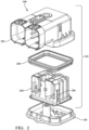
- FIG. 2 shows an exploded view of the sealed connector assembly 100.
- the first connector housing 102 includes an outer portion 202 and an inner portion 204 that may be disposed within the outer portion 202.
- the inner portion 204 defines one or more flexible arms 206 that releasably secure the inner portion 204 within the outer portion 202.
- the first connector housing 102 also includes a connector housing seal in the form of a compliant perimeter seal 208 that is disposed between the outer portion 202 and the inner portion 204 of the first connector housing 102.
- the perimeter seal 208 is formed of a compliant elastomeric material, such as an oil-bleeding silicone rubber, e.g., Dow SILASTIC ® 9201-50-LSR.
- the perimeter seal 208 has a seal side wall 302, a seal end wall 304 extending from a first end of the seal side wall 302 in a first direction, and a seal lip 306 extending from a second end of the seal side wall 302 in a second direction opposite the first direction.
- the seal side wall 302 also defines a sealing rib 308 around the circumference of the perimeter seal 208.
- the perimeter seal 208 in the illustrated example includes a pair of the sealing rib 308.
- the seal end wall 304 defines a groove 310.
- an end segment 506 of a perimeter wall 502 of the outer portion 202 defines a support rib 510 that is received within the groove 310.
- FIG. 4 shows an end cross section view of the sealed connector assembly 100 with the second connector housing 104 in a fully mated condition with the first connector housing 102.
- the seal lip 306 of the perimeter seal 208 is secured between the inner portion 204 and the outer portion 202 of the first connector housing 102.
- the second connector housing 104 is inserted into the first connector housing 102 such that a header wall 402 of the second connector housing 104 is disposed between the perimeter seal 208 and an outer wall 404 of the outer portion 202 of the first connector housing 102.
- the flexible arms 206 of the inner portion 204 of the first connector housing 102 engage a ridge 406 of the outer portion 202 to releasably secure the inner portion 204 within the outer portion 202.
- FIG. 5 shows a close-up view of the cross section view of FIG. 4 highlighting the interface between the perimeter seal 208 and the first and second connector housings 102, 104.
- the outer portion 202 has an L-shaped perimeter wall 502 which defines a side segment 504 and an end segment 506.
- the seal side wall 302 abuts the side segment 504 and the seal end wall 304 abuts the end segment 506.
- the seal lip 306 overlays an end of the side segment 504 of the perimeter wall 502.
- the inner portion 204 is disposed inside the perimeter wall 502 and has a connector lip 508 that overlies the seal lip 306 and the end of the side segment 504,
- the connector lip 508 compresses the seal lip 306 between the connector lip 508 and the end of the side segment 504, thereby retaining the perimeter seal 208 to the outer portion 202 of the first connector housing 102 and inhibiting movement and bunching of the perimeter seal 208 as the second connector housing 104 is mated with the first connector housing 102.
- the sealing ribs 308 are also resiliently compressed by the contact with the header wall 402. This compression of the sealing ribs 308 is configured to inhibit environmental contaminants, such as water, dust, or other foreign materials, from entering the interior of the first and second connector housings 102, 104.
- the seal lip 306 is curved and an apex of the seal lip 306 is thicker than the ends of the seal lip 306.
- the support rib 510 of the perimeter wall 502 is received within the groove 310 of the perimeter seal 208.
- the groove 310 and the support rib 510 may extend around the perimeter of the seal end wall 304 and the end segment 506 of the perimeter wall 502.
- the groove 310 and the support rib 510 cooperate to further inhibit movement and bunching of the perimeter seal 208 as the second connector housing 104 is mated with the first connector housing 102.
- FIG. 5 also shows that, when fully mated, a header wall 402 of the second connector housing 104 is in compressive contact with the sealing rib 308.
- the compressive contact of the header wall 402 with the sealing rib 308 and the seal end wall 304 is configured to further inhibit environmental contaminants from entering the interior of the first and second connector housings 102, 104.
- the header wall 402 may also be in compressive contact with the seal end wall 304 of the perimeter seal 208 to provide enhanced protection from intrusion of environmental contaminants into the interior of the first and second connector housings 102, 104.
- Other embodiments may be envisioned in which the header wall 402 of the second connector housing 104 is in compressive contact with the sealing rib 308 but not the seal end wall 304.
- the perimeter seal 208 is configured so that it does not "bunch up" as the second connector housing 104 is inserted within the first connector housing 102 when the perimeter seal 208 and the first and second connector housings 102, 104 are in nominal dimensional conditions.
- the sealed connector assembly 100 presented herein has been found to resist bunching of the perimeter seal 208 between the first and second connector housings 102, 104 even in maximum material conditions. This provides lower engagement forces when mating the first and second connector housings 102, 104 that enhances ergonomic performance of the sealed connector assembly 100.
- the sealed connector assembly 100 has also been found to be less susceptible to bunching of the perimeter seal 208 due to variation in the material forming the perimeter seal 208, e.g., variations in oil bleed sealing materials.
- FIG. 6 shows a flow chart of a method of manufacturing a sealed connector assembly including the following steps:
- a compliant perimeter seal is inserted within an outer portion of a connector housing.
- this step includes inserting a compliant perimeter seal 208 within an outer portion 202 of a connector housing 102.
- the perimeter seal 208 has a seal side wall 302, a seal end wall 304 extending from a first end of the seal side wall 302 in a first direction, and a curved seal lip 306 extending from a second end of the seal side wall 302 in a second direction opposite the first direction.
- the outer portion 202 has a perimeter wall 502 defining a side segment 504 and an end segment 506.
- the seal side wall is abutted against the side segment. In some embodiments, this step includes abutting the seal side wall 302 against the side segment 504.
- the seal end wall is abutted against the end segment. In some embodiments, this step includes abutting the seal end wall 304 against the end segment 506.
- the seal lip is laid over an end of the side segment of the perimeter wall.
- this step includes overlaying the seal lip 306 over an end of the side segment 504 of the perimeter wall 502.
- an inner portion of the first connector housing is inserted within a perimeter wall of the outer portion.
- this step includes inserting an inner portion 204 of the connector housing 102 within a perimeter wall 502 of the outer portion 202.
- the inner portion 204 has a connector lip 508 that overlies the seal lip 306 and an end of the side segment 504 of the perimeter wall 502.
- the seal lip is captured between the connector lip and the end of the side segment of the perimeter wall.
- this step includes capturing the seal lip 306 between the connector lip 508 and the end of the side segment 504 of the perimeter wall 502 to retain the perimeter seal 208 to the connector housing 102.
- the inner portion is attached to the outer portion.
- this step includes removably attaching the inner portion 204 of the connector housing 102 to the outer portion 202 of the connector housing 102 using an attachment feature.
- the attachment feature is a flexible arm 206 defined by the inner portion 204 of the connector housing 102 that engages a ridge 406 on the outer portion 202.
- a support rib is inserted within a groove.
- the seal end wall 304 defines a groove 310, and the end segment 506 of the perimeter wall 502 defines a support rib 510.
- this step includes inserting the support rib 510 within the groove 310.
- a second connector housing 104 is inserted within the connector housing 102.
- the connector housing 102 is a first connector housing 102
- the seal side wall 302 defines a sealing rib 308.
- this step includes inserting a second connector housing 104 within the first connector housing 102.
- a portion of the second connector housing is placed in compressive contact with the sealing rib of the perimeter seal.
- the seal side wall 302 defines a sealing rib 308.
- this step includes placing a portion of the second connector housing 104 in compressive contact with the sealing rib 308 of the perimeter seal 208.
- the header wall 402 is in compressive contact with the sealing rib 308.
- the second connector housing is further inserted within the first connector housing.
- this step includes inserting the second connector housing 104 further within the first connector housing 102.
- a portion of the second connector housing is placed in compressive contact with the seal end wall.
- this step includes placing a portion of the second connector housing 104 in compressive contact with the seal end wall 304 of the perimeter seal 208.
- the header wall 402 is in compressive contact with the seal end wall 304.
- a sealed connector assembly including: a compliant perimeter seal having a seal side wall, a seal end wall extending from a first end of the seal side wall in a first direction, and a seal lip extending from a second end of the seal side wall in a second direction opposite the first direction; and a connector housing, further including: an outer portion having a perimeter wall which defines a side segment and an end segment, the seal side wall abutting the side segment and the seal end wall abutting the end segment and the seal lip overlaying at least a portion of an end of the side segment of the perimeter wall, and an inner portion disposed inside the perimeter wall, the inner portion having a connector lip that overlies at least a portion of the seal lip and at least a portion of an end of the side segment of the perimeter wall.
- the sealed connector system of the preceding paragraph can optionally include, additionally and/or alternatively any, one or more of the following features, configurations and/or additional components.
- the techniques described herein relate to a sealed connector assembly, wherein the seal end wall defines a groove, and the end segment of the perimeter wall defines a support rib received within the groove.
- the techniques described herein relate to a sealed connector assembly, wherein the connector lip and the end of the side segment of the perimeter wall are in compressive contact with the seal lip.
- the techniques described herein relate to a sealed connector assembly, wherein the perimeter wall is L-shaped.
- the techniques described herein relate to a sealed connector assembly, wherein the inner portion of the connector housing is removably attached to the outer portion by an attachment feature.
- the techniques described herein relate to a sealed connector assembly, wherein the attachment feature is a flexible arm defined by the inner portion of the connector housing that engages a ridge on the outer portion.
- the techniques described herein relate to a sealed connector assembly, wherein the seal side wall defines a sealing rib.
- the techniques described herein relate to a sealed connector assembly, wherein the connector housing is a first connector housing, wherein the sealed connector assembly further includes a second connector housing configured to be received in the first connector housing, and wherein the second connector housing is in compressive contact with the sealing rib of the perimeter seal.
- the techniques described herein relate to a sealed connector assembly, wherein the second connector housing is in compressive contact with the seal end wall.
- the techniques described herein relate to a sealed connector assembly, wherein the perimeter seal is formed of a silicone-based rubber material, the first connector housing is formed of a polymeric material, and the second connector housing is formed of a metallic material.
- the techniques described herein relate to a sealed connector assembly, wherein the first connector housing is configured to contain a plurality of electrical terminals, and the second connector housing is configured to contain a plurality of mating electrical terminals.
- the techniques described herein relate to a sealed connector assembly, wherein the seal end wall is generally flat on one side and extends substantially perpendicularly from the seal side wall.
- the techniques described herein relate to a sealed connector assembly, wherein the seal lip curved.
- the techniques described herein relate to a sealed connector assembly, wherein an apex of the seal lip is thicker than ends of the seal lip and wherein the seal end wall is thicker than the seal lip.
- the techniques described herein relate to a method of manufacturing a sealed connector assembly, including: inserting a compliant perimeter seal within an outer portion of a first connector housing, the perimeter seal having a seal side wall, a seal end wall extending from a first end of the seal side wall in a first direction, and a curved seal lip extending from a second end of the seal side wall in a second direction opposite the first direction, the outer portion having a perimeter wall defining a side segment and an end segment; abutting the seal side wall against the side segment; abutting the seal end wall against the end segment; overlaying the seal lip over an end of the side segment of the perimeter wall; and inserting an inner portion of the first connector housing within a perimeter wall of the outer portion, the inner portion having a connector lip that overlies the seal lip and an end of the side segment of the perimeter wall; capturing the seal lip between the connector lip and the end of the side segment of the perimeter wall to retain the perimeter seal to the first connector housing.
- the method of the preceding paragraph can optionally include, additionally and/or alternatively any, one or more of the following features, configurations and/or additional components.
- the techniques described herein relate to a method, further including: removably attaching the inner portion of the connector housing to the outer portion using an attachment feature.
- the techniques described herein relate to a method, wherein the attachment feature is a flexible arm defined by the inner portion of the connector housing that engages a ridge on the outer portion.
- the techniques described herein relate to a method, wherein the seal end wall defines a groove, and the end segment of the perimeter wall defines a support rib, wherein the method additionally includes inserting the support rib within the groove.
- the techniques described herein relate to a method, wherein the connector housing is a first connector housing, wherein the seal side wall defines a sealing rib, and wherein the method additionally includes: inserting a second connector housing within the first connector housing and placing a portion of the second connector housing in compressive contact with the sealing rib of the perimeter seal.
- the techniques described herein relate to a method, wherein the method additionally includes further inserting the second connector housing within the first connector housing and placing a portion of the second connector housing in compressive contact with the seal end wall.
- 'one or more' includes a function being performed by one element, a function being performed by more than one element, e.g., in a distributed fashion, several functions being performed by one element, several functions being performed by several elements, or any combination of the above.
- first, second, etc. are, in some instances, used herein to describe various elements, these elements should not be limited by these terms. These terms are only used to distinguish one element from another.
- a first contact could be termed a second contact, and, similarly, a second contact could be termed a first contact, without departing from the scope of the various described embodiments.
- the first contact and the second contact are both contacts, but they are not the same contact.
- the term “if' is, optionally, construed to mean “when” or “upon” or “in response to determining” or “in response to detecting,” depending on the context.
- the phrase “if it is determined” or “if [a stated condition or event] is detected” is, optionally, construed to mean “upon determining” or “in response to determining” or “upon detecting [the stated condition or event]” or “in response to detecting [the stated condition or event],” depending on the context.
Landscapes
- Connector Housings Or Holding Contact Members (AREA)
Applications Claiming Priority (2)
| Application Number | Priority Date | Filing Date | Title |
|---|---|---|---|
| US202363471835P | 2023-06-08 | 2023-06-08 | |
| US18/734,265 US20240413568A1 (en) | 2023-06-08 | 2024-06-05 | Sealed connector assembly with combination connector seal |
Publications (1)
| Publication Number | Publication Date |
|---|---|
| EP4475352A1 true EP4475352A1 (de) | 2024-12-11 |
Family
ID=91435084
Family Applications (1)
| Application Number | Title | Priority Date | Filing Date |
|---|---|---|---|
| EP24180630.6A Pending EP4475352A1 (de) | 2023-06-08 | 2024-06-06 | Abgedichtete verbinderanordnung mit kombinationsverbinderdichtung |
Country Status (2)
| Country | Link |
|---|---|
| US (1) | US20240413568A1 (de) |
| EP (1) | EP4475352A1 (de) |
Citations (3)
| Publication number | Priority date | Publication date | Assignee | Title |
|---|---|---|---|---|
| JP2008192459A (ja) * | 2007-02-05 | 2008-08-21 | Fci Connectors Singapore Pte Ltd | 電気コネクタ |
| US20150372413A1 (en) * | 2014-06-24 | 2015-12-24 | Japan Aviation Electronics Industry, Limited | Waterproof connector |
| CN110998980A (zh) * | 2017-08-01 | 2020-04-10 | 德尔福技术有限公司 | 连接器组件和密封件 |
-
2024
- 2024-06-05 US US18/734,265 patent/US20240413568A1/en active Pending
- 2024-06-06 EP EP24180630.6A patent/EP4475352A1/de active Pending
Patent Citations (3)
| Publication number | Priority date | Publication date | Assignee | Title |
|---|---|---|---|---|
| JP2008192459A (ja) * | 2007-02-05 | 2008-08-21 | Fci Connectors Singapore Pte Ltd | 電気コネクタ |
| US20150372413A1 (en) * | 2014-06-24 | 2015-12-24 | Japan Aviation Electronics Industry, Limited | Waterproof connector |
| CN110998980A (zh) * | 2017-08-01 | 2020-04-10 | 德尔福技术有限公司 | 连接器组件和密封件 |
Also Published As
| Publication number | Publication date |
|---|---|
| US20240413568A1 (en) | 2024-12-12 |
Similar Documents
| Publication | Publication Date | Title |
|---|---|---|
| US9847597B2 (en) | Electrical connector with sealing structure | |
| US11848514B2 (en) | Elastomer seal spring | |
| US7229303B2 (en) | Environmentally sealed connector with blind mating capability | |
| CN102237597B (zh) | 连接器和防水连接器 | |
| EP2930795A1 (de) | Abgedichteter verbinder mit verlängerter dichtungshülle und abdichtung gegen wasserlachen | |
| EP0646991B1 (de) | Kabelklemmvorrichtung für wasserdichten Verbinder | |
| EP3413404A1 (de) | Abgedichtete elektrische verbinderanordnung und drahtdichtung | |
| US10777934B2 (en) | Electrical connector which accepts different seal configurations | |
| EP3326245A1 (de) | Anschlussstück | |
| US20030032321A1 (en) | Sealed connector | |
| CN102099973A (zh) | 防水连接器 | |
| EP4475352A1 (de) | Abgedichtete verbinderanordnung mit kombinationsverbinderdichtung | |
| CN111384634B (zh) | 连接器 | |
| US6783396B1 (en) | Airtight plug connector and terminal insert | |
| US11469539B2 (en) | Seals for a flat flexible conductor in an electrical connector assembly | |
| US9954347B1 (en) | Wire harness assembly and seal retainer therefore | |
| US12244091B2 (en) | Electrical connector having a seal with a secondary terminal locking mechanism | |
| CN103765693A (zh) | 连接器及其覆盖部件 | |
| US12500370B2 (en) | Connection device using connector | |
| US11450985B2 (en) | Connector with integrated seal retainer and secondary terminal lock | |
| CN108963560B (zh) | 连接器 | |
| EP4398426A1 (de) | Verbinderanordnung mit flexibler verriegelung und ereignisgesteuertem keil | |
| EP4343980A1 (de) | Elektrischer verbinder mit einer kabeldichtung mit einem sekundärklemmenverriegelungsmechanismus | |
| US12542396B2 (en) | Electrical connector wire seal assembly that is substantially rigid along a first axis | |
| US20220166160A1 (en) | Electrical connector and connector assembly |
Legal Events
| Date | Code | Title | Description |
|---|---|---|---|
| PUAI | Public reference made under article 153(3) epc to a published international application that has entered the european phase |
Free format text: ORIGINAL CODE: 0009012 |
|
| STAA | Information on the status of an ep patent application or granted ep patent |
Free format text: STATUS: THE APPLICATION HAS BEEN PUBLISHED |
|
| AK | Designated contracting states |
Kind code of ref document: A1 Designated state(s): AL AT BE BG CH CY CZ DE DK EE ES FI FR GB GR HR HU IE IS IT LI LT LU LV MC ME MK MT NL NO PL PT RO RS SE SI SK SM TR |
|
| STAA | Information on the status of an ep patent application or granted ep patent |
Free format text: STATUS: REQUEST FOR EXAMINATION WAS MADE |
|
| 17P | Request for examination filed |
Effective date: 20250117 |