EP4475277A1 - Mobile body - Google Patents
Mobile body Download PDFInfo
- Publication number
- EP4475277A1 EP4475277A1 EP24178354.7A EP24178354A EP4475277A1 EP 4475277 A1 EP4475277 A1 EP 4475277A1 EP 24178354 A EP24178354 A EP 24178354A EP 4475277 A1 EP4475277 A1 EP 4475277A1
- Authority
- EP
- European Patent Office
- Prior art keywords
- battery
- cooling water
- battery case
- vent holes
- mobile body
- Prior art date
- Legal status (The legal status is an assumption and is not a legal conclusion. Google has not performed a legal analysis and makes no representation as to the accuracy of the status listed.)
- Pending
Links
Images


Classifications
-
- A—HUMAN NECESSITIES
- A62—LIFE-SAVING; FIRE-FIGHTING
- A62C—FIRE-FIGHTING
- A62C3/00—Fire prevention, containment or extinguishing specially adapted for particular objects or places
- A62C3/07—Fire prevention, containment or extinguishing specially adapted for particular objects or places in vehicles, e.g. in road vehicles
- A62C3/08—Fire prevention, containment or extinguishing specially adapted for particular objects or places in vehicles, e.g. in road vehicles in aircraft
-
- H—ELECTRICITY
- H01—ELECTRIC ELEMENTS
- H01M—PROCESSES OR MEANS, e.g. BATTERIES, FOR THE DIRECT CONVERSION OF CHEMICAL ENERGY INTO ELECTRICAL ENERGY
- H01M50/00—Constructional details or processes of manufacture of the non-active parts of electrochemical cells other than fuel cells, e.g. hybrid cells
- H01M50/20—Mountings; Secondary casings or frames; Racks, modules or packs; Suspension devices; Shock absorbers; Transport or carrying devices; Holders
- H01M50/249—Mountings; Secondary casings or frames; Racks, modules or packs; Suspension devices; Shock absorbers; Transport or carrying devices; Holders specially adapted for aircraft or vehicles, e.g. cars or trains
-
- A—HUMAN NECESSITIES
- A62—LIFE-SAVING; FIRE-FIGHTING
- A62C—FIRE-FIGHTING
- A62C3/00—Fire prevention, containment or extinguishing specially adapted for particular objects or places
- A62C3/16—Fire prevention, containment or extinguishing specially adapted for particular objects or places in electrical installations, e.g. cableways
-
- B—PERFORMING OPERATIONS; TRANSPORTING
- B64—AIRCRAFT; AVIATION; COSMONAUTICS
- B64U—UNMANNED AERIAL VEHICLES [UAV]; EQUIPMENT THEREFOR
- B64U10/00—Type of UAV
- B64U10/10—Rotorcrafts
- B64U10/13—Flying platforms
- B64U10/14—Flying platforms with four distinct rotor axes, e.g. quadcopters
-
- B—PERFORMING OPERATIONS; TRANSPORTING
- B64—AIRCRAFT; AVIATION; COSMONAUTICS
- B64U—UNMANNED AERIAL VEHICLES [UAV]; EQUIPMENT THEREFOR
- B64U20/00—Constructional aspects of UAVs
- B64U20/90—Cooling
- B64U20/96—Cooling using air
-
- H—ELECTRICITY
- H01—ELECTRIC ELEMENTS
- H01M—PROCESSES OR MEANS, e.g. BATTERIES, FOR THE DIRECT CONVERSION OF CHEMICAL ENERGY INTO ELECTRICAL ENERGY
- H01M10/00—Secondary cells; Manufacture thereof
- H01M10/60—Heating or cooling; Temperature control
- H01M10/61—Types of temperature control
- H01M10/613—Cooling or keeping cold
-
- H—ELECTRICITY
- H01—ELECTRIC ELEMENTS
- H01M—PROCESSES OR MEANS, e.g. BATTERIES, FOR THE DIRECT CONVERSION OF CHEMICAL ENERGY INTO ELECTRICAL ENERGY
- H01M10/00—Secondary cells; Manufacture thereof
- H01M10/60—Heating or cooling; Temperature control
- H01M10/65—Means for temperature control structurally associated with the cells
- H01M10/656—Means for temperature control structurally associated with the cells characterised by the type of heat-exchange fluid
- H01M10/6567—Liquids
- H01M10/6568—Liquids characterised by flow circuits, e.g. loops, located externally to the cells or cell casings
-
- H—ELECTRICITY
- H01—ELECTRIC ELEMENTS
- H01M—PROCESSES OR MEANS, e.g. BATTERIES, FOR THE DIRECT CONVERSION OF CHEMICAL ENERGY INTO ELECTRICAL ENERGY
- H01M50/00—Constructional details or processes of manufacture of the non-active parts of electrochemical cells other than fuel cells, e.g. hybrid cells
- H01M50/30—Arrangements for facilitating escape of gases
- H01M50/317—Re-sealable arrangements
-
- H—ELECTRICITY
- H01—ELECTRIC ELEMENTS
- H01M—PROCESSES OR MEANS, e.g. BATTERIES, FOR THE DIRECT CONVERSION OF CHEMICAL ENERGY INTO ELECTRICAL ENERGY
- H01M50/00—Constructional details or processes of manufacture of the non-active parts of electrochemical cells other than fuel cells, e.g. hybrid cells
- H01M50/30—Arrangements for facilitating escape of gases
- H01M50/375—Vent means sensitive to or responsive to temperature
-
- H—ELECTRICITY
- H01—ELECTRIC ELEMENTS
- H01M—PROCESSES OR MEANS, e.g. BATTERIES, FOR THE DIRECT CONVERSION OF CHEMICAL ENERGY INTO ELECTRICAL ENERGY
- H01M50/00—Constructional details or processes of manufacture of the non-active parts of electrochemical cells other than fuel cells, e.g. hybrid cells
- H01M50/30—Arrangements for facilitating escape of gases
- H01M50/383—Flame arresting or ignition-preventing means
-
- H—ELECTRICITY
- H01—ELECTRIC ELEMENTS
- H01M—PROCESSES OR MEANS, e.g. BATTERIES, FOR THE DIRECT CONVERSION OF CHEMICAL ENERGY INTO ELECTRICAL ENERGY
- H01M50/00—Constructional details or processes of manufacture of the non-active parts of electrochemical cells other than fuel cells, e.g. hybrid cells
- H01M50/60—Arrangements or processes for filling or topping-up with liquids; Arrangements or processes for draining liquids from casings
- H01M50/673—Containers for storing liquids; Delivery conduits therefor
- H01M50/682—Containers for storing liquids; Delivery conduits therefor accommodated in battery or cell casings
-
- H—ELECTRICITY
- H01—ELECTRIC ELEMENTS
- H01M—PROCESSES OR MEANS, e.g. BATTERIES, FOR THE DIRECT CONVERSION OF CHEMICAL ENERGY INTO ELECTRICAL ENERGY
- H01M2200/00—Safety devices for primary or secondary batteries
- H01M2200/10—Temperature sensitive devices
-
- H—ELECTRICITY
- H01—ELECTRIC ELEMENTS
- H01M—PROCESSES OR MEANS, e.g. BATTERIES, FOR THE DIRECT CONVERSION OF CHEMICAL ENERGY INTO ELECTRICAL ENERGY
- H01M2220/00—Batteries for particular applications
- H01M2220/20—Batteries in motive systems, e.g. vehicle, ship, plane
-
- Y—GENERAL TAGGING OF NEW TECHNOLOGICAL DEVELOPMENTS; GENERAL TAGGING OF CROSS-SECTIONAL TECHNOLOGIES SPANNING OVER SEVERAL SECTIONS OF THE IPC; TECHNICAL SUBJECTS COVERED BY FORMER USPC CROSS-REFERENCE ART COLLECTIONS [XRACs] AND DIGESTS
- Y02—TECHNOLOGIES OR APPLICATIONS FOR MITIGATION OR ADAPTATION AGAINST CLIMATE CHANGE
- Y02E—REDUCTION OF GREENHOUSE GAS [GHG] EMISSIONS, RELATED TO ENERGY GENERATION, TRANSMISSION OR DISTRIBUTION
- Y02E60/00—Enabling technologies; Technologies with a potential or indirect contribution to GHG emissions mitigation
- Y02E60/10—Energy storage using batteries
Definitions
- the battery may be kept at a low temperature or may be subjected to a discharge treatment, in which, for example, the battery is submerged in water.
- a battery battery module
- a predetermined temperature for example, 100 °C
- a liquid such as water
- a housing accommodating the battery to submerge the battery in the water (liquid).
- the battery is surrounded by the housing.
- batteries mounted on aircrafts such as multicopters may require good ventilation to facilitate heat dissipation.
- FIG. 1 is a perspective view of an unmanned aerial vehicle 1 according to this embodiment.
- the unmanned aerial vehicle (hereinbelow, simply referred to as an "unmanned vehicle”) 1 is an example of a mobile body according to the present invention, and is a multicopter that obtains lift (thrust) by multiple rotary wings (propellers) 21.
- the unmanned vehicle 1 includes a main body 20 and multiple rotary wings 21.
- the multiple rotary wings 21 are provided at the distal ends of multiple arms 22 extending in four directions from the main body 20.
- the main body 20 has a rectangular box shape and includes a battery unit 5 (see FIG. 2 ) that supplies power to the respective parts of the unmanned vehicle 1.
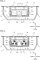
- FIG. 2 is a sectional view of the battery unit 5.
- the battery unit 5 includes a battery case 52 that accommodates one or more (in this embodiment, two) battery cells 51.
- the battery case 52 has a rectangular box shape, for example.
- First vent holes 52a communicating between the inside and the outside of the battery case 52 are formed in the side plates and the bottom plate (lower plate) of the battery case 52.
- the position, shape, number and the like of the first vent holes 52a are not particularly limited, as long as there is one first vent hole 52a provided in any of the side plates and the bottom plate of the battery case 52.
- the top plate of the battery case 52 has multiple slit holes 52b, which are holes with slits.
- the slit holes 52b are through-holes through which a fire extinguishing agent 65 and a discharge-treatment liquid, such as water, are poured into the case when the battery cells 51 ignites.
- the slit holes 52b are formed directly above the battery cells 51.
- Cooling fans 54 and a first cooling water pipe 55 for cooling the battery cells 51 are disposed in the battery case 52.
- the cooling fans 54 are disposed, for example, beside the battery cells 51 and ventilate the inside of the battery case 52 when driven.
- the first cooling water pipe 55 is routed inside the battery case 52 so as to extend along the battery cells 51, for example, and are coupled at both ends thereof to an external cooling water pump (not illustrated). When the cooling water pump is driven, the cooling water circulates through the first cooling water pipe 55 to cool the inside of the battery case 52.
- the battery case 52 is removably accommodated in a battery mount shelf 61.
- the battery case 52 can be attached to and removed from the battery mount shelf 61 by being inserted and removed in the direction perpendicular to the plane of the drawing of FIG. 2 .
- the battery mount shelf 61 is formed in a shape that is open at the top and is attached to the lower surface of a vehicle body 23 such that the opening is closed by the vehicle body 23.
- the vehicle body 23 is a part of the main body 20 of the unmanned vehicle 1.
- the battery mount shelf 61 is formed in a shape substantially corresponding to the battery case 52 at least in plan view, and accommodates the battery case 52 with almost no clearance with respect to the side plates and the bottom plate of the battery case 52.
- Second vent holes 61a corresponding to the first vent holes 52a provided in the battery case 52 are formed in the side plates and the bottom plate of the battery mount shelf 61.
- the position, shape, number and the like of the second vent holes 61a are not particularly limited, as long as there is one second vent hole 61a provided in any of the side plates and the bottom plate of the battery mount shelf 61 so as to correspond to the first vent hole 52a.
- the second vent holes 61a are provided with closing members 62 capable of closing the second vent holes 61a.
- the closing members 62 automatically close the second vent holes 61a without being electrically controlled by an external device when the temperature of the closing members 62 exceeds a predetermined temperature.
- the closing members 62 may be made of a thermally expandable refractory material.
- the thermally expandable refractory material is a refractory material that expands several to several tens of times its original size at a predetermined temperature and is used to protect buildings from fire and to prevent fire from spreading, for example.
- the closing members 62, made of the thermally expandable refractory material may be disposed on the peripheries of the second vent holes 61a so as to close the second vent holes 61a as the closing members 62 expand.
- the closing members 62 may be fireproof shutters for closing the second vent holes 61a, the shutters being positioned on one side by metallic wires that burn out at a predetermined temperature. Although it is desirable that the closing members 62 completely seal the second vent holes 61a so as not to allow air to escape when the second vent holes 61a are closed, a sealed state that does not allow leakage of a large amount of water (liquid) may be sufficient.
- An internal space S1 of the battery mount shelf 61 (more precisely, a space defined by the battery mount shelf 61 and the vehicle body 23) has a space (surplus space) above the battery case 52.
- a second cooling water pipe 64 and the fire extinguishing agent 65 are provided in this space in the internal space S1.
- the second cooling water pipe 64 may belong to the same cooling system as the first cooling water pipe 55, or may belong to a different cooling system.
- the fire extinguishing agent 65 is disposed above the battery case 52 and is fixed to the lower surface of the vehicle body 23.
- the fire extinguishing agent 65 is sealed so as to be dropped onto the battery case 52 below when the ambient temperature of the internal space S1 exceeds a predetermined temperature.
- the "predetermined temperature” is a temperature inside the internal space S1 at which the battery cells 51 are considered to have ignited.
- the fire extinguishing agent 65 be disposed at least above the slit holes 52b. However, it is sufficient that the fire extinguishing agent 65 is provided so as to automatically fall on the battery cells 51 without being controlled by an external device when the temperature exceeds the predetermined temperature.
- a pressure regulating valve 66 and a liquid supply port 67 are provided in the internal space S1 of the battery mount shelf 61.
- the pressure regulating valve 66 is disposed in the vehicle body 23 so as to communicate between the internal space S1 and the outside, and is closed in the normal state (normal time).
- the pressure regulating valve 66 communicates between the internal space S1 and the outside when the temperature reaches the predetermined temperature (or when the pressure regulating valve 66 is manually operated).
- the liquid supply port 67 is disposed in the vehicle body 23 so as to communicate between the internal space S1 and the outside, and is closed in the normal state.
- the end of the liquid supply port 67 on the outside i.e., the upper side in FIG. 2 ) is a socket to which a liquid supply hose or the like can be attached, for example.
- the battery mount shelf 61 is surrounded by a battery cover 71 from the outside.
- the battery cover 71 is exposed on the outside of the unmanned vehicle 1.
- the battery cover 71 is formed in a shape that is open at the top and is attached to the lower surface of the vehicle body 23 such that the opening is closed by the vehicle body 23.
- the battery cover 71 is disposed so as to surround the overall battery mount shelf 61 except for the top of the battery mount shelf 61 with a predetermined ventilation space S2 left between the battery cover 71 and the battery mount shelf 61.
- Vent holes 71a having a mesh structure communicating between the outside of the unmanned vehicle 1 and the ventilation space S2 are provided in the side plates of the battery cover 71. Note that the position, shape, number and the like of the vent holes 71a are not particularly limited, as long as the vent hole 71a is provided so as to communicate between the outside and the ventilation space S2.
- FIGS. 3, 4 , and 5 are sectional views illustrating the states of the battery unit 5 at the normal time, at the time of ignition, and after extinction, respectively.
- the "normal time” means the time other than an emergency including the time of ignition and after extinction.
- the battery unit 5 supplies necessary electric power, generated by the battery cells 51, to the respective parts of the unmanned vehicle 1.
- the battery cells 51 are air-cooled by the cooling fans 54 that ventilate the inside of the battery case 52.
- the air outside the unmanned vehicle 1 flows into the ventilation space S2 inside the battery cover 71 through the vent hole 71a on the front side of the unmanned vehicle 1.
- the air in the ventilation space S2 flows into the battery case 52 through the first vent hole 52a and the second vent hole 61a on the lower side, for example, to cool the battery cells 51. Then, the air flows out to the ventilation space S2 from the first vent holes 52a and the second vent holes 61a on the sides. The air flowing out of the battery case 52 into the ventilation space S2 flows out of the unmanned vehicle 1 through the vent hole 71a on the rear side of the unmanned vehicle 1, for example.
- the battery unit 5 has good ventilation.
- the heat of the battery cells 51 is appropriately removed at the normal time.
- the battery unit 5 When the battery cells 51 ignite due to some factor, the battery unit 5 performs a fire extinguishing operation.
- the closing members 62 close the second vent holes 61a in the battery mount shelf 61 to shut off the source of fire from the outside air.
- the closing members 62 according to this embodiment are made of a thermally expandable refractory material, so, when the battery cells 51 ignite, the closing members 62 are heated beyond a predetermined temperature, expand, and close the second vent holes 61a. This suppresses the spread of fire.
- a valve may be provided in the second cooling water pipe 64, so that the cooling water in the second cooling water pipe 64 is discharged when the valve is opened manually or automatically (according to the temperature).
- the valve may be replaced with another structure that enables the cooling water in the second cooling water pipe 64 to be manually or automatically discharged to the outside.
- a portion vulnerable to heat may be provided in a part of the second cooling water pipe 64, so that the cooling water inside the second cooling water pipe 64 automatically leaks out when a predetermined temperature is reached.
- first cooling water pipe 55 may also be provided with a similar structure that enables the cooling water in the first cooling water pipe 55 to be manually or automatically discharged to the outside.
- This structure enables the cooling water to be discharged to the internal space S1 of the battery mount shelf 61 to extinguish the fire on the battery cells 51.
- the fire on the battery cells 51 is extinguished by dropping the fire extinguishing agent 65 and/or discharging the cooling water.
- the internal space S1 of the battery mount shelf 61 When the cooling water is discharged to the internal space S1 of the battery mount shelf 61 at the time of extinction, the internal space S1 is filled with the cooling water, as illustrated in FIG. 5 , because the second vent holes 61a in the battery mount shelf 61 are closed by the closing members 62.
- the battery cells 51 can be submerged in water or liquid together with the battery case 52.
- the battery cells 51 can be cooled and discharged with a sufficient amount of water (liquid).
- the pressure regulating valve 66 may be opened to release the air (including the generated gas) in the internal space S1 to the outside.
- the pressure regulating valve 66 may be opened manually or automatically at the time of ignition.
- the second vent holes 61a in the battery mount shelf 61 accommodating the battery case 52 (battery cells 51) are closed by the closing members 62 when the temperature of the closing members 62 exceeds the predetermined temperature.
- the ventilation in the battery case 52 (battery cells 51) through the second vent holes 61a is ensured. Furthermore, at the time of ignition and after extinction, the internal space S1 of the battery mount shelf 61 in which the second vent holes 61a are closed is filled with the discharge-treatment liquid, so that the battery case 52 is submerged in the liquid. Thus, the discharge treatment of the battery cells 51 is properly performed to suppress the possibility of re-ignition or electric shock, and enable the battery case 52 to be safely collected.
- the battery that has good ventilation in the normal time and that is safe after extinction is achieved.
- a liquid supply member one or more of the first cooling water pipe 55, the second cooling water pipe 64, and the liquid supply port 67
- the discharge-treatment liquid can be supplied to the internal space S1 of the battery mount shelf 61.
- the closing members 62 are made of a thermally expandable refractory material that expands at a predetermined temperature, and are disposed on the peripheries of the second vent holes 61a so as to close the second vent holes 61a when the closing members 62 expand.
- the second vent holes 61a can be automatically and appropriately closed at a predetermined temperature with a simple structure without being electrically controlled.
- the fire extinguishing agent 65 that drops at a predetermined temperature is disposed in the internal space S1 of the battery mount shelf 61, above the battery case 52.
- the ignited battery case 52 (battery cells 51) can be automatically and appropriately extinguished with a simple structure without being electrically controlled.
- the battery mount shelf 61 removably accommodates the battery case 52 accommodating the battery cells 51.
- multiple battery cells 51 and other components can be formed as a module (unit), making handling of the module, including collection after extinction, easy.
- the fire on the battery cells 51 is extinguished with the fire extinguishing agent 65 and cooling water.
- the fire may be extinguished with the fire extinguishing agent 65 alone, without using cooling water.
- the first cooling water pipe 55 and the second cooling water pipe 64 are unnecessary.
- the liquid used in the cooling system of the battery cells 51 is water (cooling water) or a liquid containing additives, such as anti-freezing agent and the like.
- the second vent holes 61a in the battery mount shelf 61 are closed by the closing members 62, and the discharge-treatment liquid is supplied to the internal space S1 of the battery mount shelf 61.
- closing members may be disposed in the first vent holes 52a in the battery case 52.
- the first vent holes 52a may be closed by the closing members, and the liquid may be supplied into the battery case 52.
- the battery cells 51 can be submerged in water.
- an unmanned aerial vehicle has been described as an example of the mobile body according to the present invention.
- the present invention may be widely applied to mobile bodies, such as cars, ships, and toys of these, equipped with batteries.
- the mobile body according to the present invention can be more suitably applied to aircrafts, which face a strong demand for ventilation of the batteries at the normal time and reduction in weight of the batteries, than automobiles (electric automobiles), in which batteries are sealed in rigid housings.
- the housing in which the vent holes are closed is filled with the discharge-treatment liquid, so that the batteries are submerged in water.
- the battery that has good ventilation in the normal time and that is safe after extinction is achieved.
Landscapes
- Chemical & Material Sciences (AREA)
- General Chemical & Material Sciences (AREA)
- Electrochemistry (AREA)
- Chemical Kinetics & Catalysis (AREA)
- Engineering & Computer Science (AREA)
- Aviation & Aerospace Engineering (AREA)
- Mechanical Engineering (AREA)
- Manufacturing & Machinery (AREA)
- Emergency Management (AREA)
- Business, Economics & Management (AREA)
- Public Health (AREA)
- Health & Medical Sciences (AREA)
- Remote Sensing (AREA)
- Battery Mounting, Suspending (AREA)
- Secondary Cells (AREA)
- Connection Of Batteries Or Terminals (AREA)
Abstract
Description
- The present invention relates to a mobile body.
- Once a battery mounted on a mobile body ignites, it remains hot even after the fire is extinguished and can re-ignite. Without preventing re-ignition, it is difficult to safely collect the battery after extinction. In order to prevent re-ignition, the battery may be kept at a low temperature or may be subjected to a discharge treatment, in which, for example, the battery is submerged in water.
- For example, in the technique disclosed in Japanese Unexamined Patent Application Publication
JP 2021- 122 031 A - An aspect of the invention provides a mobile body. The mobile body includes a battery, a housing, and a closing member. The housing has a vent hole and accommodates the battery. The closing member is configured to close the vent hole when a temperature of the closing member exceeds a predetermined temperature.
- The accompanying drawings are included to provide a further understanding of the invention and are incorporated in and constitute a part of this specification. The drawings illustrate an embodiment and, together with the specification, serve to describe the principles of the invention.
-
FIG. 1 is a perspective view of an unmanned aerial vehicle according to an embodiment; -
FIG. 2 is a sectional view of a battery unit according to the embodiment; -
FIG. 3 is a sectional view illustrating the state of the battery unit at the normal time; -
FIG. 4 is a sectional view illustrating the state of the battery unit at the time of ignition; and -
FIG. 5 is a sectional view illustrating the state of the battery unit after extinction. - In the technique disclosed in
JP 2021- 122 031 A - It is desirable to provide a battery that has good ventilation in the normal time and that is safe after extinction.
- In the following, an embodiment of the invention is described in detail with reference to the accompanying drawings. Note that the following description is directed to an illustrative example of the invention and not to be construed as limiting to the invention. Factors including, without limitation, numerical values, shapes, materials, components, positions of the components, and how the components are coupled to each other are illustrative only and not to be construed as limiting to the invention.
- Further, elements in the following example embodiment which are not recited in a most-generic independent claim of the invention are optional and may be provided on an as-needed basis. The drawings are schematic and are not intended to be drawn to scale. Throughout the present specification and the drawings, elements having substantially the same function and configuration are denoted with the same numerals to avoid any redundant description.
-
FIG. 1 is a perspective view of an unmannedaerial vehicle 1 according to this embodiment. - As illustrated in
FIG. 1 , the unmanned aerial vehicle (hereinbelow, simply referred to as an "unmanned vehicle") 1 according to this embodiment is an example of a mobile body according to the present invention, and is a multicopter that obtains lift (thrust) by multiple rotary wings (propellers) 21. - For example, the
unmanned vehicle 1 includes amain body 20 and multiplerotary wings 21. - The multiple
rotary wings 21 are provided at the distal ends ofmultiple arms 22 extending in four directions from themain body 20. - The
main body 20 has a rectangular box shape and includes a battery unit 5 (seeFIG. 2 ) that supplies power to the respective parts of theunmanned vehicle 1. -
FIG. 2 is a sectional view of thebattery unit 5. - As illustrated in
FIG. 2 , thebattery unit 5 includes abattery case 52 that accommodates one or more (in this embodiment, two)battery cells 51. - The
battery case 52 has a rectangular box shape, for example. -
First vent holes 52a communicating between the inside and the outside of thebattery case 52 are formed in the side plates and the bottom plate (lower plate) of thebattery case 52. However, the position, shape, number and the like of thefirst vent holes 52a are not particularly limited, as long as there is onefirst vent hole 52a provided in any of the side plates and the bottom plate of thebattery case 52. - The top plate of the
battery case 52 hasmultiple slit holes 52b, which are holes with slits. Theslit holes 52b are through-holes through which afire extinguishing agent 65 and a discharge-treatment liquid, such as water, are poured into the case when thebattery cells 51 ignites. In this embodiment, theslit holes 52b are formed directly above thebattery cells 51. -
Cooling fans 54 and a firstcooling water pipe 55 for cooling thebattery cells 51 are disposed in thebattery case 52. - The
cooling fans 54 are disposed, for example, beside thebattery cells 51 and ventilate the inside of thebattery case 52 when driven. - The first
cooling water pipe 55 is routed inside thebattery case 52 so as to extend along thebattery cells 51, for example, and are coupled at both ends thereof to an external cooling water pump (not illustrated). When the cooling water pump is driven, the cooling water circulates through the firstcooling water pipe 55 to cool the inside of thebattery case 52. - The
battery case 52 is removably accommodated in abattery mount shelf 61. For example, thebattery case 52 can be attached to and removed from thebattery mount shelf 61 by being inserted and removed in the direction perpendicular to the plane of the drawing ofFIG. 2 . - The
battery mount shelf 61 is formed in a shape that is open at the top and is attached to the lower surface of avehicle body 23 such that the opening is closed by thevehicle body 23. Thevehicle body 23 is a part of themain body 20 of theunmanned vehicle 1. Thebattery mount shelf 61 is formed in a shape substantially corresponding to thebattery case 52 at least in plan view, and accommodates thebattery case 52 with almost no clearance with respect to the side plates and the bottom plate of thebattery case 52. -
Second vent holes 61a corresponding to thefirst vent holes 52a provided in thebattery case 52 are formed in the side plates and the bottom plate of thebattery mount shelf 61. Thesecond vent holes 61a, together with thefirst vent holes 52a provided at the corresponding positions, communicate between the inside of thebattery case 52 and the outside of thebattery mount shelf 61. - Note that the position, shape, number and the like of the
second vent holes 61a are not particularly limited, as long as there is onesecond vent hole 61a provided in any of the side plates and the bottom plate of thebattery mount shelf 61 so as to correspond to thefirst vent hole 52a. - The
second vent holes 61a are provided withclosing members 62 capable of closing thesecond vent holes 61a. Theclosing members 62 automatically close thesecond vent holes 61a without being electrically controlled by an external device when the temperature of theclosing members 62 exceeds a predetermined temperature. - For example, the
closing members 62 may be made of a thermally expandable refractory material. The thermally expandable refractory material is a refractory material that expands several to several tens of times its original size at a predetermined temperature and is used to protect buildings from fire and to prevent fire from spreading, for example. Theclosing members 62, made of the thermally expandable refractory material, may be disposed on the peripheries of thesecond vent holes 61a so as to close thesecond vent holes 61a as theclosing members 62 expand. - The structure of the
closing members 62 is not particularly limited as long as theclosing members 62 close thesecond vent holes 61a when the temperature of theclosing members 62 exceeds a predetermined temperature. - For example, the
closing members 62 may be fireproof shutters for closing thesecond vent holes 61a, the shutters being positioned on one side by metallic wires that burn out at a predetermined temperature. Although it is desirable that the closingmembers 62 completely seal thesecond vent holes 61a so as not to allow air to escape when thesecond vent holes 61a are closed, a sealed state that does not allow leakage of a large amount of water (liquid) may be sufficient. - An internal space S1 of the battery mount shelf 61 (more precisely, a space defined by the
battery mount shelf 61 and the vehicle body 23) has a space (surplus space) above thebattery case 52. A secondcooling water pipe 64 and thefire extinguishing agent 65 are provided in this space in the internal space S1. - The second
cooling water pipe 64 is attached to the side plates of thebattery mount shelf 61, near thebattery case 52, for example. Both ends of the secondcooling water pipe 64 are coupled to an external cooling water pump (not illustrated). - When the cooling water pump is driven, the cooling water circulates through the second
cooling water pipe 64 to cool thebattery case 52. The secondcooling water pipe 64 may belong to the same cooling system as the firstcooling water pipe 55, or may belong to a different cooling system. - The
fire extinguishing agent 65 is disposed above thebattery case 52 and is fixed to the lower surface of thevehicle body 23. Thefire extinguishing agent 65 is sealed so as to be dropped onto thebattery case 52 below when the ambient temperature of the internal space S1 exceeds a predetermined temperature. The "predetermined temperature" is a temperature inside the internal space S1 at which thebattery cells 51 are considered to have ignited. - It is preferable that the
fire extinguishing agent 65 be disposed at least above the slit holes 52b. However, it is sufficient that thefire extinguishing agent 65 is provided so as to automatically fall on thebattery cells 51 without being controlled by an external device when the temperature exceeds the predetermined temperature. - Furthermore, a
pressure regulating valve 66 and aliquid supply port 67 are provided in the internal space S1 of thebattery mount shelf 61. - The
pressure regulating valve 66 is disposed in thevehicle body 23 so as to communicate between the internal space S1 and the outside, and is closed in the normal state (normal time). Thepressure regulating valve 66 communicates between the internal space S1 and the outside when the temperature reaches the predetermined temperature (or when thepressure regulating valve 66 is manually operated). - The
liquid supply port 67 is disposed in thevehicle body 23 so as to communicate between the internal space S1 and the outside, and is closed in the normal state. The end of theliquid supply port 67 on the outside (i.e., the upper side inFIG. 2 ) is a socket to which a liquid supply hose or the like can be attached, for example. - By attaching the liquid supply hose or the like to the outside end of the
liquid supply port 67, a discharge-treatment liquid can be supplied from the outside to the internal space S1. - The
battery mount shelf 61 is surrounded by abattery cover 71 from the outside. - The
battery cover 71 is exposed on the outside of theunmanned vehicle 1. For example, thebattery cover 71 is formed in a shape that is open at the top and is attached to the lower surface of thevehicle body 23 such that the opening is closed by thevehicle body 23. - The
battery cover 71 is disposed so as to surround the overallbattery mount shelf 61 except for the top of thebattery mount shelf 61 with a predetermined ventilation space S2 left between thebattery cover 71 and thebattery mount shelf 61. -
Vent holes 71a having a mesh structure communicating between the outside of theunmanned vehicle 1 and the ventilation space S2 are provided in the side plates of thebattery cover 71. Note that the position, shape, number and the like of thevent holes 71a are not particularly limited, as long as thevent hole 71a is provided so as to communicate between the outside and the ventilation space S2. - Next, the function and the operation of the
battery unit 5 will be described. -
FIGS. 3, 4 , and5 are sectional views illustrating the states of thebattery unit 5 at the normal time, at the time of ignition, and after extinction, respectively. - The "normal time" means the time other than an emergency including the time of ignition and after extinction.
- At the normal time (for example, when the
unmanned vehicle 1 is flying), thebattery unit 5 supplies necessary electric power, generated by thebattery cells 51, to the respective parts of theunmanned vehicle 1. - At this time, as illustrated in
FIG. 3 , thebattery cells 51 are air-cooled by the coolingfans 54 that ventilate the inside of thebattery case 52. For example, first, the air outside theunmanned vehicle 1 flows into the ventilation space S2 inside thebattery cover 71 through thevent hole 71a on the front side of theunmanned vehicle 1. - The air in the ventilation space S2 flows into the
battery case 52 through thefirst vent hole 52a and thesecond vent hole 61a on the lower side, for example, to cool thebattery cells 51. Then, the air flows out to the ventilation space S2 from thefirst vent holes 52a and thesecond vent holes 61a on the sides. The air flowing out of thebattery case 52 into the ventilation space S2 flows out of theunmanned vehicle 1 through thevent hole 71a on the rear side of theunmanned vehicle 1, for example. - In this way, the
battery unit 5 has good ventilation. Thus, the heat of thebattery cells 51 is appropriately removed at the normal time. - Also at this time, the
battery case 52 is water-cooled (liquid-cooled) by the cooling water flowing through the firstcooling water pipe 55 and the secondcooling water pipe 64. For example, the cooling water is circulated through the firstcooling water pipe 55 inside thebattery case 52 and the secondcooling water pipe 64 outside thebattery case 52 by the cooling water pump (not illustrated). The firstcooling water pipe 55 directly cools thebattery cells 51, and the secondcooling water pipe 64 indirectly cools thebattery cells 51 from the outside of thebattery case 52. - When the
battery cells 51 ignite due to some factor, thebattery unit 5 performs a fire extinguishing operation. - As illustrated in
FIG. 4 , the closingmembers 62 close thesecond vent holes 61a in thebattery mount shelf 61 to shut off the source of fire from the outside air. The closingmembers 62 according to this embodiment are made of a thermally expandable refractory material, so, when thebattery cells 51 ignite, the closingmembers 62 are heated beyond a predetermined temperature, expand, and close thesecond vent holes 61a. This suppresses the spread of fire. - As the ambient temperature rises due to the ignition of the
battery cells 51, thefire extinguishing agent 65 disposed above thebattery case 52 melts and drops. Thefire extinguishing agent 65 drops onto thebattery case 52 below, passes through the slit holes 52b, and falls on thebattery cells 51 in thebattery case 52 to extinguish the fire. - Alternatively, a valve may be provided in the second
cooling water pipe 64, so that the cooling water in the secondcooling water pipe 64 is discharged when the valve is opened manually or automatically (according to the temperature). The valve may be replaced with another structure that enables the cooling water in the secondcooling water pipe 64 to be manually or automatically discharged to the outside. - For example, a portion vulnerable to heat may be provided in a part of the second
cooling water pipe 64, so that the cooling water inside the secondcooling water pipe 64 automatically leaks out when a predetermined temperature is reached. - Furthermore, the first
cooling water pipe 55 may also be provided with a similar structure that enables the cooling water in the firstcooling water pipe 55 to be manually or automatically discharged to the outside. - This structure enables the cooling water to be discharged to the internal space S1 of the
battery mount shelf 61 to extinguish the fire on thebattery cells 51. - As described above, the fire on the
battery cells 51 is extinguished by dropping thefire extinguishing agent 65 and/or discharging the cooling water. - When the cooling water is discharged to the internal space S1 of the
battery mount shelf 61 at the time of extinction, the internal space S1 is filled with the cooling water, as illustrated inFIG. 5 , because thesecond vent holes 61a in thebattery mount shelf 61 are closed by the closingmembers 62. - When the amount of water in the internal space S1 is insufficient (for example, when the
battery case 52 is not completely submerged in the water), or when the cooling water has not been discharged to extinguish the fire, the cooling water may be further discharged, or a discharge-treatment liquid may be supplied to the internal space S1 from the outside through theliquid supply port 67. - By doing so, the
battery cells 51 can be submerged in water or liquid together with thebattery case 52. Thus, thebattery cells 51 can be cooled and discharged with a sufficient amount of water (liquid). - The discharge-treatment liquid to be supplied to the internal space S1 is not particularly limited as long as it promotes discharge of the
battery cells 51. Examples of the liquid include sodium chloride solution having a predetermined concentration, water, an anionic surface active agent disclosed inJapanese Patent No. 6847716 JP 2005 347 162 A - When the liquid is supplied, the
pressure regulating valve 66 may be opened to release the air (including the generated gas) in the internal space S1 to the outside. Thepressure regulating valve 66 may be opened manually or automatically at the time of ignition. - As described above, according to this embodiment, the
second vent holes 61a in thebattery mount shelf 61 accommodating the battery case 52 (battery cells 51) are closed by the closingmembers 62 when the temperature of the closingmembers 62 exceeds the predetermined temperature. - Thus, in the normal time, the ventilation in the battery case 52 (battery cells 51) through the
second vent holes 61a is ensured. Furthermore, at the time of ignition and after extinction, the internal space S1 of thebattery mount shelf 61 in which thesecond vent holes 61a are closed is filled with the discharge-treatment liquid, so that thebattery case 52 is submerged in the liquid. Thus, the discharge treatment of thebattery cells 51 is properly performed to suppress the possibility of re-ignition or electric shock, and enable thebattery case 52 to be safely collected. - Hence, the battery that has good ventilation in the normal time and that is safe after extinction is achieved.
- Furthermore, according to this embodiment, there is provided a liquid supply member (one or more of the first
cooling water pipe 55, the secondcooling water pipe 64, and the liquid supply port 67) through which the discharge-treatment liquid can be supplied to the internal space S1 of thebattery mount shelf 61. - This enables the discharge-treatment liquid to be quickly supplied to the internal space S1 at the time of ignition or after extinction. Thus, the
battery cells 51 can be appropriately extinguished or submerged in water. - Furthermore, according to this embodiment, the closing
members 62 are made of a thermally expandable refractory material that expands at a predetermined temperature, and are disposed on the peripheries of thesecond vent holes 61a so as to close thesecond vent holes 61a when the closingmembers 62 expand. - Thus, the
second vent holes 61a can be automatically and appropriately closed at a predetermined temperature with a simple structure without being electrically controlled. - According to this embodiment, the
fire extinguishing agent 65 that drops at a predetermined temperature is disposed in the internal space S1 of thebattery mount shelf 61, above thebattery case 52. - Thus, the ignited battery case 52 (battery cells 51) can be automatically and appropriately extinguished with a simple structure without being electrically controlled.
- According to this embodiment, the
battery mount shelf 61 removably accommodates thebattery case 52 accommodating thebattery cells 51. - With this structure,
multiple battery cells 51 and other components can be formed as a module (unit), making handling of the module, including collection after extinction, easy. - Although the embodiment of the present invention has been described above, the present invention is not limited to the above-described embodiment.
- For example, in the above embodiment, the fire on the
battery cells 51 is extinguished with thefire extinguishing agent 65 and cooling water. However, the fire may be extinguished with thefire extinguishing agent 65 alone, without using cooling water. In this case, the firstcooling water pipe 55 and the secondcooling water pipe 64 are unnecessary. - The liquid used in the cooling system of the
battery cells 51 is water (cooling water) or a liquid containing additives, such as anti-freezing agent and the like. - In the above embodiment, the
second vent holes 61a in thebattery mount shelf 61 are closed by the closingmembers 62, and the discharge-treatment liquid is supplied to the internal space S1 of thebattery mount shelf 61. However, closing members may be disposed in thefirst vent holes 52a in thebattery case 52. At the time of ignition, thefirst vent holes 52a may be closed by the closing members, and the liquid may be supplied into thebattery case 52. Also with this structure, thebattery cells 51 can be submerged in water. - In the above-described embodiment, an unmanned aerial vehicle has been described as an example of the mobile body according to the present invention. However, the present invention may be widely applied to mobile bodies, such as cars, ships, and toys of these, equipped with batteries.
- However, the mobile body according to the present invention can be more suitably applied to aircrafts, which face a strong demand for ventilation of the batteries at the normal time and reduction in weight of the batteries, than automobiles (electric automobiles), in which batteries are sealed in rigid housings.
- The details described in the above embodiment can be appropriately modified without departing from the scope of the present invention.
- According to the present invention, the vent holes in the housing accommodating the batteries are closed by the closing members when the temperature of the closing members exceeds the predetermined temperature. Thus, in the normal time, ventilation of the battery through the vent hole is ensured.
- Furthermore, at the time of ignition or after extinction, the housing in which the vent holes are closed is filled with the discharge-treatment liquid, so that the batteries are submerged in water. Hence, the battery that has good ventilation in the normal time and that is safe after extinction is achieved.
Claims (5)
- A mobile body comprising:- a battery (51);- a housing (61) having a vent hole (52a, 61a) and accommodating the battery (51); and- a closing member (62) configured to close the vent hole (52a, 61a) when a temperature of the closing member (62) exceeds a predetermined temperature.
- The mobile body according to claim 1,
further comprising a liquid supply member (67) configured to supply a discharge-treatment liquid into the housing (61). - The mobile body according to claim 1 or 2,
wherein the closing member (62) is made of a thermally expandable refractory material configured to expand at a predetermined temperature, and is disposed on a periphery of the vent hole (52a, 61a) so as to close the vent hole (52a, 61a) when the closing member (62) expands. - The mobile body according to any one of claims 1 to 3, wherein a fire extinguishing agent (65) configured drop at a predetermined temperature is disposed above the battery (51) in the housing (61).
- The mobile body according to any one of claims 1 to 4, wherein the battery (51) is a battery cell (51)accommodated in a case (52), and the housing (61) removably accommodates the case (52).
Applications Claiming Priority (1)
| Application Number | Priority Date | Filing Date | Title |
|---|---|---|---|
| JP2023092268A JP2024174443A (en) | 2023-06-05 | 2023-06-05 | Mobile |
Publications (1)
| Publication Number | Publication Date |
|---|---|
| EP4475277A1 true EP4475277A1 (en) | 2024-12-11 |
Family
ID=91302356
Family Applications (1)
| Application Number | Title | Priority Date | Filing Date |
|---|---|---|---|
| EP24178354.7A Pending EP4475277A1 (en) | 2023-06-05 | 2024-05-28 | Mobile body |
Country Status (4)
| Country | Link |
|---|---|
| US (1) | US20240405357A1 (en) |
| EP (1) | EP4475277A1 (en) |
| JP (1) | JP2024174443A (en) |
| CN (1) | CN119079171A (en) |
Citations (6)
| Publication number | Priority date | Publication date | Assignee | Title |
|---|---|---|---|---|
| JP2010503038A (en) | 2006-09-06 | 2010-01-28 | ライカ マイクロシステムズ ツェーエムエス ゲーエムベーハー | Method for scanning a sample and microscopy system |
| JP2011254906A (en) * | 2010-06-07 | 2011-12-22 | Nohmi Bosai Ltd | Fire extinguishing apparatus |
| US20200176741A1 (en) * | 2017-12-15 | 2020-06-04 | Lg Chem, Ltd. | Battery pack having improved stability |
| FR3089425A1 (en) * | 2018-12-11 | 2020-06-12 | Arianegroup Sas | System suitable for extinguishing a battery fire |
| JP6847716B2 (en) | 2017-03-09 | 2021-03-24 | 太平洋セメント株式会社 | Discharging method and processing method of waste lithium-ion batteries |
| EP3890053A1 (en) * | 2018-12-28 | 2021-10-06 | Contemporary Amperex Technology Co., Limited | Battery pack |
-
2023
- 2023-06-05 JP JP2023092268A patent/JP2024174443A/en active Pending
-
2024
- 2024-04-23 CN CN202410489361.0A patent/CN119079171A/en active Pending
- 2024-05-28 EP EP24178354.7A patent/EP4475277A1/en active Pending
- 2024-05-29 US US18/676,803 patent/US20240405357A1/en active Pending
Patent Citations (6)
| Publication number | Priority date | Publication date | Assignee | Title |
|---|---|---|---|---|
| JP2010503038A (en) | 2006-09-06 | 2010-01-28 | ライカ マイクロシステムズ ツェーエムエス ゲーエムベーハー | Method for scanning a sample and microscopy system |
| JP2011254906A (en) * | 2010-06-07 | 2011-12-22 | Nohmi Bosai Ltd | Fire extinguishing apparatus |
| JP6847716B2 (en) | 2017-03-09 | 2021-03-24 | 太平洋セメント株式会社 | Discharging method and processing method of waste lithium-ion batteries |
| US20200176741A1 (en) * | 2017-12-15 | 2020-06-04 | Lg Chem, Ltd. | Battery pack having improved stability |
| FR3089425A1 (en) * | 2018-12-11 | 2020-06-12 | Arianegroup Sas | System suitable for extinguishing a battery fire |
| EP3890053A1 (en) * | 2018-12-28 | 2021-10-06 | Contemporary Amperex Technology Co., Limited | Battery pack |
Also Published As
| Publication number | Publication date |
|---|---|
| CN119079171A (en) | 2024-12-06 |
| JP2024174443A (en) | 2024-12-17 |
| US20240405357A1 (en) | 2024-12-05 |
Similar Documents
| Publication | Publication Date | Title |
|---|---|---|
| CN114512904B (en) | Energy storage cabinet | |
| ES2963900T3 (en) | Fire extinguishing device | |
| KR102390607B1 (en) | Method and apparatus for managing thermal runaway gases in battery systems | |
| US20150056482A1 (en) | Battery pack with a fire preventing agent | |
| CN113611936B (en) | Energy storage lithium battery thermal runaway management device and installation control method thereof | |
| JP2011254906A (en) | Fire extinguishing apparatus | |
| AU2022354509B2 (en) | Battery storage system comprising at least two battery modules | |
| WO2016032101A1 (en) | Energy storage system | |
| US20240405357A1 (en) | Mobile body | |
| CN118236653A (en) | Fireproof partition fire extinguishing device, fire extinguishing method and lithium battery energy storage system | |
| CN218351530U (en) | Lithium battery explosion-proof structure | |
| JP2026004395A (en) | Improved safety of the battery pack | |
| CN113764755A (en) | Forced circulation cooling heat dissipation device of energy storage lithium battery pack and installation control method thereof | |
| CN209859997U (en) | Battery box and energy storage battery cabinet with fire protection structure | |
| CN218586204U (en) | Energy storage lithium cell conflagration automatic control device | |
| CN223309125U (en) | Mobile emergency energy storage device and energy storage equipment | |
| CN217690868U (en) | Pneumatic load switch device | |
| CN219717128U (en) | Water system energy storage cabinet with fire control function | |
| CN116387676A (en) | Battery pack | |
| CN222735061U (en) | Battery packs and electrical equipment | |
| CN223066263U (en) | Energy storage container | |
| CN219106424U (en) | An integrated device for heat dissipation and thermal runaway protection of a battery pack | |
| CN223680316U (en) | Battery pack and electric equipment | |
| CN222380724U (en) | Box structure of mobile energy storage container, mobile energy storage container and mobile energy storage vehicle | |
| CN223785243U (en) | An energy storage system |
Legal Events
| Date | Code | Title | Description |
|---|---|---|---|
| PUAI | Public reference made under article 153(3) epc to a published international application that has entered the european phase |
Free format text: ORIGINAL CODE: 0009012 |
|
| STAA | Information on the status of an ep patent application or granted ep patent |
Free format text: STATUS: THE APPLICATION HAS BEEN PUBLISHED |
|
| AK | Designated contracting states |
Kind code of ref document: A1 Designated state(s): AL AT BE BG CH CY CZ DE DK EE ES FI FR GB GR HR HU IE IS IT LI LT LU LV MC ME MK MT NL NO PL PT RO RS SE SI SK SM TR |
|
| STAA | Information on the status of an ep patent application or granted ep patent |
Free format text: STATUS: REQUEST FOR EXAMINATION WAS MADE |
|
| 17P | Request for examination filed |
Effective date: 20250611 |
|
| GRAP | Despatch of communication of intention to grant a patent |
Free format text: ORIGINAL CODE: EPIDOSNIGR1 |
|
| STAA | Information on the status of an ep patent application or granted ep patent |
Free format text: STATUS: GRANT OF PATENT IS INTENDED |
|
| INTG | Intention to grant announced |
Effective date: 20260210 |
|
| RIC1 | Information provided on ipc code assigned before grant |
Ipc: H01M 10/613 20140101AFI20260202BHEP Ipc: H01M 10/635 20140101ALI20260202BHEP Ipc: H01M 50/204 20210101ALI20260202BHEP Ipc: H01M 50/317 20210101ALI20260202BHEP Ipc: H01M 50/375 20210101ALI20260202BHEP Ipc: H01M 50/249 20210101ALI20260202BHEP Ipc: H01M 50/383 20210101ALI20260202BHEP Ipc: H01M 50/682 20210101ALI20260202BHEP |