EP4475124A2 - Verfahren zur herunterabtastung eines audiosignals - Google Patents
Verfahren zur herunterabtastung eines audiosignals Download PDFInfo
- Publication number
- EP4475124A2 EP4475124A2 EP24209945.5A EP24209945A EP4475124A2 EP 4475124 A2 EP4475124 A2 EP 4475124A2 EP 24209945 A EP24209945 A EP 24209945A EP 4475124 A2 EP4475124 A2 EP 4475124A2
- Authority
- EP
- European Patent Office
- Prior art keywords
- signal
- subband
- filter bank
- filterbank
- transposition
- Prior art date
- Legal status (The legal status is an assumption and is not a legal conclusion. Google has not performed a legal analysis and makes no representation as to the accuracy of the status listed.)
- Granted
Links
Images


Classifications
-
- G—PHYSICS
- G10—MUSICAL INSTRUMENTS; ACOUSTICS
- G10L—SPEECH ANALYSIS TECHNIQUES OR SPEECH SYNTHESIS; SPEECH RECOGNITION; SPEECH OR VOICE PROCESSING TECHNIQUES; SPEECH OR AUDIO CODING OR DECODING
- G10L21/00—Speech or voice signal processing techniques to produce another audible or non-audible signal, e.g. visual or tactile, in order to modify its quality or its intelligibility
- G10L21/02—Speech enhancement, e.g. noise reduction or echo cancellation
- G10L21/0208—Noise filtering
- G10L21/0216—Noise filtering characterised by the method used for estimating noise
- G10L21/0232—Processing in the frequency domain
-
- G—PHYSICS
- G10—MUSICAL INSTRUMENTS; ACOUSTICS
- G10L—SPEECH ANALYSIS TECHNIQUES OR SPEECH SYNTHESIS; SPEECH RECOGNITION; SPEECH OR VOICE PROCESSING TECHNIQUES; SPEECH OR AUDIO CODING OR DECODING
- G10L19/00—Speech or audio signals analysis-synthesis techniques for redundancy reduction, e.g. in vocoders; Coding or decoding of speech or audio signals, using source filter models or psychoacoustic analysis
- G10L19/008—Multichannel audio signal coding or decoding using interchannel correlation to reduce redundancy, e.g. joint-stereo, intensity-coding or matrixing
-
- G—PHYSICS
- G10—MUSICAL INSTRUMENTS; ACOUSTICS
- G10L—SPEECH ANALYSIS TECHNIQUES OR SPEECH SYNTHESIS; SPEECH RECOGNITION; SPEECH OR VOICE PROCESSING TECHNIQUES; SPEECH OR AUDIO CODING OR DECODING
- G10L19/00—Speech or audio signals analysis-synthesis techniques for redundancy reduction, e.g. in vocoders; Coding or decoding of speech or audio signals, using source filter models or psychoacoustic analysis
- G10L19/02—Speech or audio signals analysis-synthesis techniques for redundancy reduction, e.g. in vocoders; Coding or decoding of speech or audio signals, using source filter models or psychoacoustic analysis using spectral analysis, e.g. transform vocoders or subband vocoders
- G10L19/0204—Speech or audio signals analysis-synthesis techniques for redundancy reduction, e.g. in vocoders; Coding or decoding of speech or audio signals, using source filter models or psychoacoustic analysis using spectral analysis, e.g. transform vocoders or subband vocoders using subband decomposition
-
- G—PHYSICS
- G10—MUSICAL INSTRUMENTS; ACOUSTICS
- G10L—SPEECH ANALYSIS TECHNIQUES OR SPEECH SYNTHESIS; SPEECH RECOGNITION; SPEECH OR VOICE PROCESSING TECHNIQUES; SPEECH OR AUDIO CODING OR DECODING
- G10L21/00—Speech or voice signal processing techniques to produce another audible or non-audible signal, e.g. visual or tactile, in order to modify its quality or its intelligibility
- G10L21/02—Speech enhancement, e.g. noise reduction or echo cancellation
- G10L21/038—Speech enhancement, e.g. noise reduction or echo cancellation using band spreading techniques
-
- G—PHYSICS
- G10—MUSICAL INSTRUMENTS; ACOUSTICS
- G10L—SPEECH ANALYSIS TECHNIQUES OR SPEECH SYNTHESIS; SPEECH RECOGNITION; SPEECH OR VOICE PROCESSING TECHNIQUES; SPEECH OR AUDIO CODING OR DECODING
- G10L21/00—Speech or voice signal processing techniques to produce another audible or non-audible signal, e.g. visual or tactile, in order to modify its quality or its intelligibility
- G10L21/04—Time compression or expansion
Definitions
- the present invention relates to the downsampling of an audio signal or to an audio source coding systems which make use of a harmonic transposition method for high frequency reconstruction (HFR), and to digital effect processors, e.g. so-called exciters, where generation of harmonic distortion adds brightness to the processed signal, and to time stretchers, where the duration of a signal is extended while maintaining the spectral content of the original.
- HFR high frequency reconstruction
- PCT WO 98/57436 the concept of transposition was established as a method to recreate a high frequency band from a lower frequency band of an audio signal.
- a substantial saving in bitrate can be obtained by using this concept in audio coding.
- a low bandwidth signal is processed by a core waveform coder and the higher frequencies are regenerated using transposition and additional side information of very low bitrate describing the target spectral shape at the decoder side.
- the bandwidth of the core coded signal is narrow, it becomes increasingly important to recreate a high band with perceptually pleasant characteristics.
- the harmonic transposition defined in PCT WO 98/57436 performs very well for complex musical material in a situation with low crossover frequency.
- a harmonic transposition is that a sinusoid with frequency ⁇ is mapped to a sinusoid with frequency T ⁇ where T > 1 is an integer defining the order of transposition.
- a single sideband modulation (SSB) based HFR method maps a sinusoid with frequency ⁇ to a sinusoid with frequency ⁇ + ⁇ ⁇ where ⁇ ⁇ is a fixed frequency shift. Given a core signal with low bandwidth, a dissonant ringing artifact can result from SSB transposition.
- SSB single sideband modulation
- Subband block based harmonic transposition is another HFR method used to suppress intermodulation products, in which case a filter bank with coarser frequency resolution and a lower degree of oversampling is employed, e.g. a multichannel QMF bank.
- a time block of complex subband samples is processed by a common phase modifier while the superposition of several modified samples forms an output subband sample. This has the net effect of suppressing intermodulation products which would otherwise occur when the input subband signal consists of several sinusoids.
- Transposition based on block based subband processing has much lower computational complexity than the high quality transposers and reaches almost the same quality for many signals.
- SSB copy-up patching introduces unwanted roughness into the audio signal, but is computationally simple and preserves the time envelope of transients. Moreover, the computational complexity is significantly increased over the computational very simple SSB copy-up method.
- EP 1940023 A2 discloses a bank of digital filters that can be cascade connected. It also relates to a reception circuit comprising such a bank of cascaded filters.
- the bank of cascadable digital filters has: at the input, a frequency transposition circuit for the digital signal.
- a polyphase filter receives as input the frequency-transposed digital signal clocked at the sampling frequency Fs.
- the polyphase filter has an FFT filter having a number N of points.
- the output of the filtering device retains a given number of outputs of the FFT filter so that the information bit rate at the output of the device is equal to the information bit rate at the input.
- the bank of digital filters is particularly applicable to heterodyne-type radar signal receivers.
- sampling rates are of particular importance. This is due to the fact that a high sampling rate means a high complexity and a low sampling rate generally means low complexity due to the reduced number of required operations.
- the situation in bandwidth extension applications is particularly so that the sampling rate of the core coder output signal will typically be so low that this sampling rate is too low for a full bandwidth signal.
- a bandwidth extension by for example a factor of 2 means that an upsampling operation is required so that the sampling rate of the bandwidth extended signal is so high that the sampling can "cover" the additionally generated high frequency components.
- filterbanks such as analysis filterbanks and synthesis filterbanks are responsible for a considerable amount of processing operations.
- the size of the filterbanks i.e. whether the filterbank is a 32 channel filterbank, a 64 channel filterbank or even a filterbank with a higher number of channels will significantly influence the complexity of the audio processing algorithm.
- a high number of filterbank channels requires more processing operations and, therefore, higher complexity than a small number of filterbank channels.
- This object is achieved by a method for downsampling an audio signal in accordance with claim 1, or a computer program in accordance with claim 2.
- an apparatus for processing an input audio signal comprises a synthesis filterbank for synthesizing an audio intermediate signal from the input audio signal, where the input audio signal is represented by a plurality of first subband signals generated by an analysis filterbank placed in processing direction before the synthesis filterbank, wherein a number of filterbank channels of the synthesis filterbank is smaller than a number of channels of the analysis filterbank.
- the intermediate signal is furthermore processed by a further analysis filterbank for generating a plurality of second subband signals from the audio intermediate signal, wherein the further analysis filterbank has a number of channels being different from the number of channels of the synthesis filterbank so that a sampling rate of a subband signal of the plurality of subband signals is different from a sampling rate of a first subband signal of the plurality of first subband signals generated by the analysis filterbank.
- the cascade of a synthesis filterbank and a subsequently connected further analysis filterbank provides a sampling rate conversion and additionally a modulation of the bandwidth portion of the original audio input signal which has been input into the synthesis filterbank to a base band.
- This time intermediate signal that has now been extracted from the original input audio signal which can, for example, be the output signal of a core decoder of a bandwidth extension scheme, is now represented preferably as a critically sampled signal modulated to the base band, and it has been found that this representation, i.e.
- the resampled output signal when being processed by a further analysis filterbank to obtain a subband representation allows a low complexity processing of further processing operations which may or may not occur and which can, for example, be bandwidth extension related processing operations such as non-linear subband operations followed by high frequency reconstruction processing and by a merging of the subbands in the final synthesis filterbank.
- the present application provides different aspects of apparatuses, methods or computer programs for processing audio signals in the context of bandwidth extension and in the context of other audio applications, which are not related to bandwidth extension.
- the features of the subsequently described and claimed individual aspects can be partly or fully combined, but can also be used separately from each other, since the individual aspects already provide advantages with respect to perceptual quality, computational complexity and processor/memory resources when implemented in a computer system or micro processor.
- Embodiments provide a method to reduce the computational complexity of a subband block based harmonic HFR method by means of efficient filtering and sampling rate conversion of the input signals to the HFR filter bank analysis stages. Further, the bandpass filters applied to the input signals can be shown to be obsolete in a subband block based transposer.
- the present embodiments help to reduce the computational complexity of subband block based harmonic transposition by efficiently implementing several orders of subband block based transposition in the framework of a single analysis and synthesis filter bank pair.
- a suitable sub-set of orders or all orders of transposition can be performed jointly within a filterbank pair.
- a combined transposition scheme where only certain transposition orders are calculated directly whereas the remaining bandwidth is filled by replication of available, i.e. previously calculated, transposition orders (e.g. 2 nd order) and/or the core coded bandwidth.
- patching can be carried out using every conceivable combination of available source ranges for replication
- embodiments provide a method to improve both high quality harmonic HFR methods as well as subband block based harmonic HFR methods by means of spectral alignment of HFR tools.
- increased performance is achieved by aligning the spectral borders of the HFR generated signals to the spectral borders of the envelope adjustment frequency table.
- the spectral borders of the limiter tool are by the same principle aligned to the spectral borders of the HFR generated signals.
- Further embodiments are configured for improving the perceptual quality of transients and at the same time reducing computational complexity by, for example, application of a patching scheme that applies a mixed patching consisting of harmonic patching and copy-up patching.
- the individual filterbanks of the cascaded filterbank structure are quadrature mirror filterbanks (QMF), which all rely on a lowpass prototype filter or window modulated using a set of modulation frequencies defining the center frequencies of the filterbank channels.
- QMF quadrature mirror filterbanks
- all window functions or prototype filters depend on each other in such a way that the filters of the filterbanks with different sizes (filterbank channels) depend on each other as well.
- the largest filterbank in a cascaded structure of filterbanks comprising, in embodiments, a first analysis filterbank, a subsequently connected filterbank, a further analysis filterbank, and at some later state of processing a final synthesis filter bank, has a window function or prototype filter response having a certain number of window function or prototype filter coefficients.
- the smaller sized filterbanks are all sub-sampled version of this window function, which means that the window functions for the other filterbanks are sub-sampled versions of the "large" window function. For example, if a filterbank has half the size of the large filterbank, then the window function has half the number of coefficients, and the coefficients of the smaller sized filterbanks are derived by sub-sampling. In this situation, the sub-sampling means that e.g. every second filter coefficient is taken for the smaller filterbank having half the size.
- Embodiments of the present invention are particularly useful in situations where only a portion of the input audio signal is required for further processing, and this situation particularly occurs in the context of harmonic bandwidth extension.
- vocoder-like processing operations are particularly preferred.
- the embodiments provide a lower complexity for a QMF transposer by efficient time and frequency domain operations and an improved audio quality for QMF and DFT based harmonic spectral band replication using spectral alignment.
- Embodiments relate to audio source coding systems employing an e.g. subband block based harmonic transposition method for high frequency reconstruction (HFR), and to digital effect processors, e.g. so-called exciters, where generation of harmonic distortion adds brightness to the processed signal, and to time stretchers, where the duration of a signal is extended while maintaining the spectral content of the original.
- Embodiments provide a method to reduce the computational complexity of a subband block based harmonic HFR method by means of efficient filtering and sampling rate conversion of the input signals prior to the HFR filter bank analysis stages. Further, embodiments show that the conventional bandpass filters applied to the input signals are obsolete in a subband block based HFR system.
- embodiments provide a method to improve both high quality harmonic HFR methods as well as subband block based harmonic HFR methods by means of spectral alignment of HFR tools.
- embodiments teach how increased performance is achieved by aligning the spectral borders of the HFR generated signals to the spectral borders of the envelope adjustment frequency table. Further, the spectral borders of the limiter tool are by the same principle aligned to the spectral borders of the HFR generated signals.
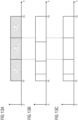
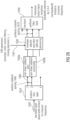
- Fig. 23 illustrates a preferred implementation of the apparatus for processing an input audio signal, where the input audio signal can be a time domain input signal on line 2300 output by, for example, a core audio decoder 2301.
- the input audio signal is input into a first analysis filterbank 2302 which is, for example, an analysis filterbank having M channels.
- the analysis filterbank is a critically sampled analysis filterbank.
- the analysis filterbank 2302 provides, for each block of M input samples on line 2300 a single sample for each subband channel.
- the analysis filterbank 2302 is a complex modulated filterbank which means that each subband sample has a magnitude and a phase or equivalently a real part and an imaginary part.
- the input audio signal on line 2300 is represented by a plurality of first subband signals 2303 which are generated by the analysis filterbank 2302.
- a subset of all first subband signals is input into a synthesis filterbank 2304.
- the synthesis filterbank 2304 has Ms channels, where Ms is smaller than M. Hence, not all the subband signals generated by filterbank 2302 are input into synthesis filterbank 2304, but only a subset, i.e. a certain smaller amount of channels as indicated by 2305.
- the subset 2305 covers a certain intermediate bandwidth, but alternatively, the subset can also cover a bandwidth starting with filterbank channel 1 of the filterbank 2302 until a channel having a channel number smaller than M, or alternatively the subset 2305 can also cover a group of subband signals aligned with the highest channel M and extended to a lower channel having a channel number higher than channel number 1.
- the channel indexing can be started with zero depending on the actually used notation.
- a certain intermediate bandwidth represented by the group of subband signals indicated at 2305 is input into the synthesis filterbank 2304.
- the other channels not belonging to the group 2305 are not input into the synthesis filterbank 2304.
- the synthesis filterbank 2304 generates an intermediate audio signal 2306, which has a sampling rate equal to fs ⁇ Ms/M. Since Ms is smaller than M, the sampling rate of the intermediate signal 2306 will be smaller than the sampling rate of the input audio signal on line 2300.
- the intermediate signal 2306 represents a downsampled and demodulated signal corresponding to the bandwidth signal represented by subbands 2305, where the signal is demodulated to the base band, since the lowest channel of group 2305 is input into channel 1 of the Ms synthesis filterbank and the highest channel of block 2305 is input into the highest input of block 2304, apart from some zero padding operations for the lowest or the highest channel in order to avoid aliasing problems at the borders of the subset 2305.
- the apparatus for processing an input audio signal furthermore comprises a further analysis filterbank 2307 for analyzing the intermediate signal 2306, and the further analysis filterbank has M A channels, where M A is different from Ms and preferably is greater than Ms.
- the sampling rate of the subband signals output by the further analysis filterbank 2307 and indicated at 2308 will be lower than the sampling rate of a subband signal 2303.
- M A is lower than Ms
- the sampling rate of a subband signal 2308 will be higher than a sampling rate of a subband signal of the plurality of first subband signals 2303.
- the cascade of filterbanks 2304 and 2307 provides very efficient and high quality upsampling or downsampling operations or generally a very efficient resampling processing tool.
- the plurality of second subband signals 2308 are preferably further processed in a processor 2309 which performs the processing with the data resampled by the cascade of filterbanks 2304, 2307 (and preferably 2302). Additionally, it is preferred that block 2309 also performs an upsampling operation for bandwidth extension processing operations so that in the end the subbands output by block 2309 are at the same sampling rate as the subbands output by block 2302.
- these subbands are input together with additional subbands indicated at 2310, which are preferably the low band subbands as, for example, generated by the analysis filterbank 2302 into a synthesis filterbank 2311, which finally provides a processed time domain signal, for example a bandwidth extended signal having a sampling rate 2fs.
- This sampling rate output by the block 2311 is in this embodiment 2 times the sampling rate of the signal on line 2300, and this sampling rate output by block 2311 is large enough so that the additional bandwidth generated by the processing in block 2309 can be represented in the processed time domain signal with high audio quality.
- the filterbank 2302 can be in a separate device and an apparatus for processing an input audio signal may only comprise the synthesis filterbank 2304 and the further analysis filterbank 2307.
- the analysis filterbank 2302 can be distributed separately from a "post"-processor comprising blocks 2304, 2307 and, depending on the implementation, blocks 2309 and 2311, too.
- the application of the present invention implementing cascaded filterbanks can be different in that a certain device comprises the analysis filterbank 2302 and the smaller synthesis filterbank 2304, and the intermediate signal is provided to a different processor distributed by a different distributor or via a different distribution channel. Then, the combination of the analysis filterbank 2302 and the smaller synthesis filterbank 2304 represents a very efficient way of downsampling and at the same time demodulating the bandwidth signal represented by the subset 2305 to the base band. This downsampling and demodulation to the base band has been performed without any loss in audio quality, and particularly without any loss in audio information and therefore is a high quality processing.
- the table in Fig. 23 illustrates certain exemplary numbers for the different devices.
- the analysis filterbank 2302 has 32 channels
- the synthesis filterbank has 12 channels
- the further analysis filterbank has 2 times the channels of the synthesis filterbank, such as 24 channels
- the final synthesis filterbank 2311 has 64 channels.
- the number of channels in the analysis filterbank 2302 is big
- the number of channels in the synthesis filterbank 2304 is small
- the number of channels in the further analysis filterbank 2307 is medium
- the number of channels in the synthesis filterbank 2311 is very large.
- the sampling rates of the subband signals output by the analysis filterbank 2302 is fs/M.
- the intermediate signal has a sampling rate fs ⁇ Ms/M.
- the subband channels of the further analysis filterbank indicated at 2308 have a sampling rate of fs ⁇ Ms/(M ⁇ M A ), and the synthesis filterbank 2311 provides an output signal having a sampling rate of 2fs, when the processing in block 2309 doubles the sampling rate.
- the processing in block 2309 does not double the sampling rate, then the sampling rate output by the synthesis filterbank will be correspondingly lower.
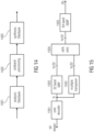
- Fig. 14 illustrates the principle of subband block based transposition.
- the input time domain signal is fed to an analysis filterbank 1401 which provides a multitude of complex valued subband signals. These are fed to the subband processing unit 1402.
- the multitude of complex valued output subbands is fed to the synthesis filterbank 1403, which in turn outputs the modified time domain signal.
- the subband processing unit 1402 performs nonlinear block based subband processing operations such that the modified time domain signal is a transposed version of the input signal corresponding to a transposition order T > 1.
- the notion of a block based subband processing is defined by comprising nonlinear operations on blocks of more than one subband sample at a time, where subsequent blocks are windowed and overlap added to generate the output subband signals.
- the filterbanks 1401 and 1403 can be of any complex exponential modulated type such as QMF or a windowed DFT. They can be evenly or oddly stacked in the modulation and can be defined from a wide range of prototype filters or windows. It is important to know the quotient ⁇ f S / ⁇ f A of the following two filter bank parameters, measured in physical units.
- Fig. 15 illustrates an example scenario for the application of subband block based transposition using several orders of transposition in a HFR enhanced audio codec.
- a transmitted bit-stream is received at the core decoder 1501, which provides a low bandwidth decoded core signal at a sampling frequency fs.
- the low frequency is resampled to the output sampling frequency 2 fs by means of a complex modulated 32 band QMF analysis bank 1502 followed by a 64 band QMF synthesis bank (Inverse QMF) 1505.
- the high frequency content of the output signal is obtained by feeding the higher subbands of the 64 band QMF synthesis bank 1505 with the output bands from the multiple transposer unit 1503, subject to spectral shaping and modification performed by the HFR processing unit 1504.
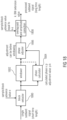
- Fig. 16 illustrates a prior art example scenario for the operation of a multiple order subband block based transposition 1603 applying a separate analysis filter bank per transposition order.
- the merge unit 1604 simply selects and combines the relevant subbands from each transposition factor branch into a single multitude of QMF subbands to be fed into the HFR processing unit.
- the exemplary system includes a sampling rate converter 1601-3 which converts the input sampling rate down by a factor 3/2 from fs to 2 fs / 3.
- the exemplary system includes a sampling rate converter 1601-4 which converts the input sampling rate down by a factor two from fs to fs / 2.
- Fig. 17 illustrates an example scenario for the efficient operation of a multiple order subband block based transposition applying a single 64 band QMF analysis filter bank.
- the current embodiment teaches to replace the two branches 1601-3 ⁇ 1602-3 ⁇ 1603-3 and 1601-4 ⁇ 1602-4 --7 1603-4 by the subband processing 1703-3 and 1703-4, respectively, whereas the branch 1602-2 ⁇ 1603-2 is kept unchanged compared to Fig 16 . All three orders of transposition will now have to be performed in a filterbank domain with reference to Fig.
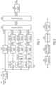
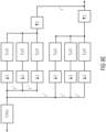
- Fig. 1 illustrates the operation of a subband block based transposer using transposition orders of 2, 3, and 4 in a HFR enhanced decoder framework, such as SBR [ISO/IEC 14496-3:2009, "Information technology - Coding of audio-visual objects - Part 3: Audio].
- the bitstream is decoded to the time domain by the core decoder 101 and passed to the HFR module 103, which generates a high frequency signal from the base band core signal.
- the HFR generated signal is dynamically adjusted to match the original signal as close as possible by means of transmitted side information. This adjustment is performed by the HFR processor 105 on subband signals, obtained from one or several analysis QMF banks.
- a typical scenario is where the core decoder operates on a time domain signal sampled at half the frequency of the input and output signals, i.e. the HFR decoder module will effectively resample the core signal to twice the sampling frequency.
- This sample rate conversion is usually obtained by the first step of filtering the core coder signal by means of a 32-band analysis QMF bank 102.
- the subbands below the so-called crossover frequency i.e. the lower subset of the 32 subbands that contains the entire core coder signal energy, are combined with the set of subbands that carry the HFR generated signal.
- the number of so combined subbands is 64, which, after filtering through the synthesis QMF bank 106, results in a sample rate converted core coder signal combined with the output from the HFR module.
- the input time domain signal is bandpass filtered in the blocks 103-12, 103-13 and 103-14. This is done in order to make the output signals, processed by the different transposition orders, to have non-overlapping spectral contents.
- the signals are further downsampled ( 103-23, 103-24 ) to adapt the sampling rate of the input signals to fit analysis filter banks of a constant size (in this case 64).
- the increase of the sampling rate, from fs to 2fs, can be explained by the fact that the sampling rate converters use downsampling factors of T /2 instead of T, in which the latter would result in transposed subband signals having equal sampling rate as the input signal.
- the downsampled signals are fed to separate HFR analysis filter banks ( 103-32, 103-33 and 103-34 ), one for each transposition order, which provide a multitude of complex valued subband signals. These are fed to the non-linear subband stretching units ( 103-42, 103-43 and 103-44 ).
- the multitude of complex valued output subbands are fed to the Merge/Combine module 104 together with the output from the subsampled analysis bank 102.
- the Merge/Combine unit simply merges the subbands from the core analysis filter bank 102 and each stretching factor branch into a single multitude of QMF subbands to be fed into the HFR processing unit 105.
- the transposed signals need to be of bandpass character.
- the traditional bandpass filters 103-12-103-14 in Fig. 1 the separate bandpass filters are redundant and can be avoided.
- the inherent bandpass characteristic provided by the QMF bank is exploited by feeding the different contributions from the transposer branches independently to different subband channels in 104. It also suffices to apply the time stretching only to bands which are combined in 104.
- Fig. 2 illustrates the operation of a nonlinear subband stretching unit.
- the block extractor 201 samples a finite frame of samples from the complex valued input signal.
- the frame is defined by an input pointer position.
- This frame undergoes nonlinear processing in 202 and is subsequently windowed by a finite length window in 203.
- the resulting samples are added to previously output samples in the overlap and add unit 204 where the output frame position is defined by an output pointer position.
- the input pointer is incremented by a fixed amount and the output pointer is incremented by the subband stretch factor times the same amount. An iteration of this chain of operations will produce an output signal with duration being the subband stretch factor times the input subband signal duration, up to the length of the synthesis window.
- a harmonic transposer While the SSB transposer employed by SBR [ISO/IEC 14496-3:2009, "Information technology - Coding of audio-visual objects - Part 3: Audio] typically exploits the entire base band, excluding the first subband, to generate the high band signal, a harmonic transposer generally uses a smaller part of the core coder spectrum. The amount used, the so-called source range, depends on the transposition order, the bandwidth extension factor, and the rules applied for the combined result, e.g. if the signals generated from different transposition orders are allowed to overlap spectrally or not. As a consequence, just a limited part of the harmonic transposer output spectrum for a given transposition order will actually be used by the HFR processing module 105.
- Fig. 18 illustrates another embodiment of an exemplary processing implementation for processing a single subband signal.
- the single subband signal has been subjected to any kind of decimation either before or after being filtered by an analysis filter bank not shown in Fig. 18 . Therefore, the time length of the single subband signal is shorter than the time length before forming the decimation.
- the single subband signal is input into a block extractor 1800, which can be identical to the block extractor 201, but which can also be implemented in a different way.
- the block extractor 1800 in Fig. 18 operates using a sample/block advance value exemplarily called e.
- the sample/block advance value can be variable or can be fixedly set and is illustrated in Fig. 18 as an arrow into block extractor box 1800.
- the block extractor 1800 At the output of the block extractor 1800, there exists a plurality of extracted blocks. These blocks are highly overlapping, since the sample/block advance value e is significantly smaller than the block length of the block extractor.
- the block extractor extracts blocks of 12 samples. The first block comprises samples 0 to 11, the second block comprises samples 1 to 12, the third block comprises samples 2 to 13, and so on.
- the sample/block advance value e is equal to 1, and there is a 11-fold overlapping.
- the individual blocks are input into a windower 1802 for windowing the blocks using a window function for each block.
- a phase calculator 1804 is provided, which calculates a phase for each block.
- the phase calculator 1804 can either use the individual block before windowing or subsequent to windowing.
- a phase adjustment value p x k is calculated and input into a phase adjuster 1806.
- the phase adjuster applies the adjustment value to each sample in the block.
- the factor k is equal to the bandwidth extension factor.
- the corrected phase for synthesis is k * p, p + (k-1)*p. So in this example the correction factor is either 2, if multiplied or 1*p if added.
- Other values/rules can be applied for calculating the phase correction value.
- the single subband signal is a complex subband signal
- the phase of a block can be calculated by a plurality of different ways.
- One way is to take the sample in the middle or around the middle of the block and to calculate the phase of this complex sample. It is also possible to calculate the phase for every sample.
- a phase adjustor operates subsequent to the windower
- these two blocks can also be interchanged, so that the phase adjustment is performed to the blocks extracted by the block extractor and a subsequent windowing operation is performed. Since both operations, i.e., windowing and phase adjustment are real-valued or complex-valued multiplications, these two operations can be summarized into a single operation using a complex multiplication factor, which, itself, is the product of a phase adjustment multiplication factor and a windowing factor.
- the phase-adjusted blocks are input into an overlap/add and amplitude correction block 1808, where the windowed and phase-adjusted blocks are overlap-added.
- the sample/block advance value in block 1808 is different from the value used in the block extractor 1800.
- the sample/block advance value in block 1808 is greater than the value e used in block 1800, so that a time stretching of the signal output by block 1808 is obtained.
- the processed subband signal output by block 1808 has a length which is longer than the subband signal input into block 1800.
- the sample/block advance value is used, which is two times the corresponding value in block 1800. This results in a time stretching by a factor of two.
- other sample/block advance values can be used so that the output of block 1808 has a required time length.
- an amplitude correction is preferably performed in order to address the issue of different overlaps in block 1800 and 1808.
- This amplitude correction could, however, be also introduced into the windower/phase adjustor multiplication factor, but the amplitude correction can also be performed subsequent to the overlap/processing.
- the sample/block advance value for the overlap/add block 1808 would be equal to two, when a bandwidth extension by a factor of two is performed. This would still result in an overlap of five blocks.
- the sample/block advance value used by block 1808 would be equal to three, and the overlap would drop to an overlap of three.
- the overlap/add block 1808 would have to use a sample/block advance value of four, which would still result in an overlap of more than two blocks.
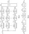
- Fig. 3 The basic block scheme of such a system for a subband block based HFR generator is illustrated in Fig. 3 .
- the input core coder signal is processed by dedicated downsamplers preceding the HFR analysis filter banks.
- each downsampler filter out the source range signal and to deliver that to the analysis filter bank at the lowest possible sampling rate.
- lowest possible refers to the lowest sampling rate that is still suitable for the downstream processing, not necessarily the lowest sampling rate that avoids aliasing after decimation.
- the sampling rate conversion may be obtained in various manners. Without limiting the scope of the invention, two examples will be given: the first shows the resampling performed by multi-rate time domain processing, and the second illustrates the resampling achieved by means of QMF subband processing.
- Fig. 4 shows an example of the blocks in a multi-rate time domain downsampler for a transposition order of 2.
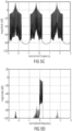
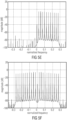
- Figs. 5(a) and (b) Examples of an input signal and the spectrum after modulation is depicted in Figs. 5(a) and (b) .
- the modulated signal is interpolated ( 402 ) and filtered by a complex-valued lowpass filter with passband limits 0 and B /2 Hz ( 403 ).
- the spectra after the respective steps are shown in Figs. 5(c) and (d) .
- the filtered signal is subsequently decimated ( 404 ) and the real part of the signal is computed ( 405 ).
- the results after these steps are shown in Figs. 5(e) and (f) .
- T 2
- P 2 is chosen as 24, in order to safely cover the source range.
- the interpolation factor is 3 (as seen from Fig. 5(c) ) and the decimation factor is 8.
- the decimator can be moved all the way to the left, and the interpolator all the way to the right in Fig. 4 . In this way, the modulation and filtering are done on the lowest possible sampling rate and computational complexity is further decreased.
- Another approach is to use the subband outputs from the subsampled 32-band analysis QMF bank 102 already present in the SBR HFR method.
- the subbands covering the source ranges for the different transposer branches are synthesized to the time domain by small subsampled QMF banks preceding the HFR analysis filter banks.
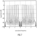
- This type of HFR system is illustrated in Fig. 6 .
- the small QMF banks are obtained by subsampling the original 64-band QMF bank, where the prototype filter coefficients are found by linear interpolation of the original prototype filter.
- the first (index 8) and last (index 19) bands are set to zero.
- the resulting spectral output is shown in Fig. 7 .
- element 601 of Fig. 6 corresponds to the analysis filterbank 2302 of Fig. 23 .
- the synthesis filterbank 2304 of Fig. 23 corresponds to element 602-2
- the further analysis filterbank 2307 of Fig. 23 corresponds to element 603-2.
- Block 604-2 corresponds to block 2309 and the combiner 605 may correspond to the synthesis filterbank 2311, but in other embodiments, the combiner can be configured to output subband signals and, then, a further synthesis filterbank connected to the combiner can be used.
- a certain high frequency reconstruction as discussed in the context of Fig. 26 later on can be performed before synthesis filtering by synthesis filterbank 2311 or combiner 205, or can be performed subsequent to synthesis filtering in synthesis filterbank 2311 of Fig. 23 or subsequent to the combiner in block 605 of Fig. 6 .
- the other branches extending from 602-3 to 604-3 or extending from 602-T to 604-T are not illustrated in Fig. 23 , but can be implemented in a similar manner, but with different sizes of filterbanks where T in Fig. 6 corresponds to a transposition factor.
- the transposition by a transposition factor of 3 and the transposition by a transposition factor of 4 can be introduced into the processing branch consisting of element 602-2 to 604-2 so that block 604-2 does not only provide a transposition by a factor of 2 but also a transposition by a factor of 3 and a factor of 4, together with a certain synthesis filterbank is used as discussed in the context of Figs. 26 and 27 .
- Q 2 corresponds to Ms and Ms is equal to, for example, 12.
- Ms is equal to, for example, 12.
- the size of the further analysis filterbank 603-2 corresponding to element 2307 is equal to 2Ms such as 24 in the embodiment.
- the lowest subband channel and the highest subband channel of the synthesis filterbank 2304 can be fed with zeroes in order to avoid aliasing problems.
- Fig. 1 The system outlined in Fig. 1 can be viewed as a simplified special case of the resampling outlined in Figs. 3 and 4 .
- the modulators are omitted.
- all HFR analysis filtering are obtained using 64-band analysis filter banks.
- the downsampling factors are 1, 1.5 and 2 for the 2 nd , 3 rd and 4 th order transposer branches respectively.
- the subband signals from the 32-band analysis QMF bank corresponding to block 2302 of Fig. 23 or 601 of Fig. 6 as defined in MPEG4 can be used.
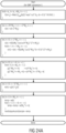
- the definition of this analysis filterbank in the MPEG-4 Standard is illustrated in the upper portion of Fig. 25a and is illustrated as a flowchart in Fig. 25b , which is also taken from the MPEG-4 Standard.
- the SBR (spectral bandwidth replication) portion of this standard is incorporated herein by reference.
- the analysis filterbank 2302 of Fig. 23 or the 32-band QMF 601 of Fig. 6 can be implemented as illustrated in Fig. 25a , upper portion and the flowchart in Fig. 25b .
- synthesis filterbank illustrated in block 2311 of Fig. 23 can also be implemented as indicated in the lower portion of Fig. 25a and as illustrated in the flowchart of Fig. 25c .
- any other filterbank definitions can be applied, but at least for the analysis filterbank 2302, the implementation illustrated in Figs. 25a and 25b is preferred due to the robustness, stability and high quality provided by this MPEG-4 analysis filterbank having 32 channels at least in the context of bandwidth extension applications such as spectral bandwidth replication, or stated generally, high frequency reconstruction processing applications.
- the synthesis filterbank 2304 is configured for synthesizing a subset of the subbands covering the source range for a transposer. This synthesis is done for synthesizing the intermediate signal 2306 in the time domain.
- the synthesis filterbank 2304 is a small sub-sampled real-valued QMF bank.
- the time domain output 2306 of this filterbank is then fed to a complex-valued analysis QMF bank of twice the filterbank size.
- This QMF bank is illustrated by block 2307 of Fig. 23 .
- This procedure enables a substantial saving in computational complexity as only the relevant source range is transformed to the QMF subband domain having doubled frequency resolution.
- the small QMF banks are obtained by sub-sampling of the original 64-band QMF bank, where the prototype filter coefficients are obtained by linear interpolation of the original prototype filter.
- the prototype filter associated with the MPEG-4 synthesis filterbank having 640 samples is used, where the MPEG-4 analysis filterbank has a window of 320 window samples.
- Ms is the size of the sub-sampled synthesis filter bank
- k L represents the subband index of the first channel from the 32-band QMF bank to enter the sub-sampled synthesis filter bank.
- the array startSubband2kL is listed in Table 1.
- the function floor ⁇ x ⁇ rounds the argument x to the nearest integer towards minus infinity.
- the value Ms defines the size of the synthesis filterbank 2304 of Fig. 23 and K L is the first channel of the subset 2305 indicated at Fig. 23 .
- the value in the equation f tableLow is defined in ISO/IEC 14496-3, section 4.6.18.3.2 which is also incorporated herein by reference. It is to be noted that the value Ms goes in increments of 4, which means that the size of the synthesis filterbank 2304 can be 4, 8, 12, 16, 20, 24, 28, or 32.
- the synthesis filterbank 2304 is a real-valued synthesis filter bank.
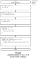
- a set of Ms real-valued subband samples is calculated from the Ms new complex-valued subband samples according to the first step of Fig. 24a .
- exp() denotes the complex exponential function
- i is the imaginary unit
- k L has been defined before.
- the output from this operation is stored in the positions 0 to 2 M S -1 of array v.
- the synthesis filterbank has a prototype window function calculator for calculating a prototype window function by subsampling or interpolating using a stored window function for a filterbank having a different size.
- the further analysis filterbank 2307 has a prototype window function calculator for calculating a prototype window function by subsampling or interpolating using a stored window function for a filterbank having a different size.
- exp() denotes the complex exponential function
- i is the imaginary unit.
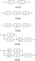
- FIG. 8(a) A block diagram of a factor 2 downsampler is shown in Fig. 8(a) .
- B ( z ) is the non-recursive part (FIR)
- a ( z ) is the recursive part (IIR).
- the filter can be factored as shown in Fig. 8(b) .
- the recursive part may be moved past the decimator as in Fig. 8(c) .
- the downsampler may be structured as in Fig. 8(d) .
- the FIR part is computed at the lowest possible sampling rate as shown in Fig. 8(e) .
- the FIR operation delay, decimators and polyphase components
- the FIR operation can be viewed as a window-add operation using an input stride of two samples. For two input samples, one new output sample will be produced, effectively resulting in a downsampling of a factor 2.
- B ( z ) is the non-recursive part (FIR)
- a ( z ) is the recursive part (IIR).
- the recursive part may be moved in front of the interpolator as in Fig. 9(c) .
- the downsampler may be structured as in Fig. 9(d) .
- the FIR part is computed at the lowest possible sampling rate as shown in Fig. 9(e) .
- the even-indexed output samples are computed using the lower group of three polyphase filters ( E 0 ( z ), E 2 ( z ), E 4 ( z )) while the odd-indexed samples are computed from the higher group ( E 1 ( z ), E 3 ( z ), E 5 ( z )).
- the operation of each group (delay chain, decimators and polyphase components) can be viewed as a window-add operation using an input stride of three samples.
- the window coefficients used in the upper group are the odd indexed coefficients, while the lower group uses the even index coefficients from the original filter B ( z ). Hence, for a group of three input samples, two new output samples will be produced, effectively resulting in a downsampling of a factor 1.5.
- the time domain signal from the core decoder may also be subsampled by using a smaller subsampled synthesis transform in the core decoder.
- the use of a smaller synthesis transform offers even further decreased computational complexity.
- the ratio of the synthesis transform size and the nominal size Q ( Q ⁇ 1) results in a core coder output signal having a sampling rate Qfs.
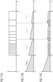
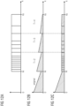
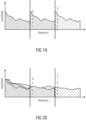
- Fig. 10 illustrates the alignment of the spectral borders of the HFR transposer signals to the spectral borders of the envelope adjustment frequency table in a HFR enhanced coder, such as SBR [ISO/IEC 14496-3:2009, "Information technology - Coding of audio-visual objects - Part 3: Audio].
- Fig. 10(a) shows a stylistic graph of the frequency bands comprising the envelope adjustment table, the so-called scale-factor bands, covering the frequency range from the cross-over frequency k x to the stop frequency k s .
- the scale-factor bands constitute the frequency grid used in a HFR enhanced coder when adjusting the energy level of the regenerated high-band frequency, i.e. the frequency envelope.
- the signal energy is averaged over a time/frequency block constrained by the scale-factor band borders and selected time borders. If the signals generated by different transposition orders are unaligned to the scale-factor bands, as illustrated in Fig. 10(b) , artifacts may arise if the spectral energy drastically changes in the vicinity of a transposition band border, since the envelope adjustment process will maintain the spectral structure within one scale-factor band.
- FIG. 11(a) again shows the scale-factor band borders.
- Fig. 11(c) shows the envelope adjusted signal when a flat target envelope is assumed.
- the blocks with checkered areas represent scale-factor bands with high intra-band energy variations, which may cause anomalies in the output signal.
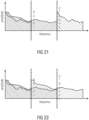
- Fig. 12 illustrates the scenario of Fig. 11 , but this time using aligned borders.
- Fig. 12(a) shows the scale-factor band borders
- Fig. 12(c) shows the envelope adjusted signal when a flat target envelope is assumed.
- Fig. 13 illustrates the adaption of the HFR limiter band borders, as described in e.g. SBR [ISO/IEC 14496-3:2009, "Information technology - Coding of audio-visual objects - Part 3: Audio] to the harmonic patches in a HFR enhanced coder.
- the limiter operates on frequency bands having a much coarser resolution than the scale-factor bands, but the principle of operation is very much the same.
- an average gain-value for each of the limiter bands is calculated.
- the individual gain values i.e. the envelope gain values calculated for each of the scale-factor bands, are not allowed to exceed the limiter average gain value by more than a certain multiplicative factor.
- the objective of the limiter is to suppress large variations of the scale-factor band gains within each of the limiter bands. While the adaption of the transposer generated bands to the scale-factor bands ensures small variations of the intra-band energy within a scale-factor band, the adaption of the limiter band borders to the transposer band borders handles the larger scale energy differences between the transposer processed bands.
- Fig. 13(b) shows the frequency bands of the limiter which typically are of constant width on a logarithmic frequency scale.
- transposer frequency band borders are added as constant limiter borders and the remaining limiter borders are recalculated to maintain the logarithmic relations as close as possible, as for example illustrated in Fig. 13(c) .
- a block or device corresponds to a method step or a feature of a method step.
- aspects described in the context of a method step also represent a description of a corresponding block or item or feature of a corresponding apparatus.
- a BWE comprises several patches.
- the higher patches require high transposition factors within the phase vocoders, which particularly deteriorate the perceptual quality of transients.
- examples generate the patches of higher order that occupy the upper spectral regions preferably by computationally efficient SSB copy-up patching and the lower order patches covering the middle spectral regions, for which the preservation of the harmonic structure is desired, preferably by HBE patching.
- the individual mix of patching methods can be static over time or, preferably, be signaled in the bitstream.
- the low frequency information can be used as shown in Fig. 21 .
- the data from patches that were generated using HBE methods can be used as illustrated in Fig. 21 .
- the latter leads to a less dense tonal structure for higher patches.
- every combination of copy-up and HBE is conceivable.
- Fig. 26 illustrates a preferred processing chain for the purpose of bandwidth extension, where different processing operations can be performed within the non-linear subband processing indicated at blocks 1020a, 1020b.
- the cascade of filterbanks 2302, 2304, 2307 is represented in Fig. 26 by block 1010.
- block 2309 may correspond to elements 1020a, 1020b and the envelope adjuster 1030 can be placed between block 2309 and block 2311 of Fig. 23 or can be placed subsequent to the processing in block 2311.
- the band-selective processing of the processed time domain signal such as the bandwidth extended signal is performed in the time domain rather than in the subband domain, which exists before the synthesis filterbank 2311.
- Fig. 26 illustrates an apparatus for generating a bandwidth extended audio signal from a lowband input signal 1000 in accordance with a further embodiment.
- the apparatus comprises an analysis filterbank 1010, a subband-wise non-linear subband processor 1020a, 1020b, a subsequently connected envelope adjuster 1030 or, generally stated, a high frequency reconstruction processor operating on high frequency reconstruction parameters as, for example, input at parameter line 1040.
- the envelope adjuster or as generally stated, the high frequency reconstruction processor processes individual subband signals for each subband channel and inputs the processed subband signals for each subband channel into a synthesis filterbank 1050.
- the synthesis filterbank 1050 receives, at its lower channel input signals, a subband representation of the lowband core decoder signal.
- the lowband can also be derived from the outputs of the analysis filterbank 1010 in Fig. 26 .
- the transposed subband signals are fed into higher filterbank channels of the synthesis filterbank for performing high frequency reconstruction.
- the filterbank 1050 finally outputs a transposer output signal which comprises bandwidth extensions by transposition factors 2, 3, and 4, and the signal output by block 1050 is no longer bandwidth-limited to the crossover frequency, i.e. to the highest frequency of the core coder signal corresponding to the lowest frequency of the SBR or HFR generated signal components.
- the analysis filterbank performs a two times over sampling and has a certain analysis subband spacing 1060.
- the synthesis filterbank 1050 has a synthesis subband spacing 1070 which is, in this embodiment, double the size of the analysis subband spacing which results in a transposition contribution as will be discussed later in the context of Fig. 27 .
- Fig. 27 illustrates a detailed implementation of a preferred embodiment of a non-linear subband processor 1020a in Fig. 26 .
- the circuit illustrated in Fig. 27 receives as an input a single subband signal 108, which is processed in three "branches":
- the upper branch 110a is for a transposition by a transposition factor of 2.
- the branch in the middle of Fig. 27 indicated at 110b is for a transposition by a transposition factor of 3
- the lower branch in Fig. 27 is for a transposition by a transposition factor of 4 and is indicated by reference numeral 110c.
- the actual transposition obtained by each processing element in Fig. 27 is only 1 (i.e. no transposition) for branch 110a.
- Branch 110b has a decimation functionality in order to obtain a transposition by 1.5. Due to the fact that the synthesis filterbank has two times the physical subband spacing of the analysis filterbank, a transposition factor of 3 is obtained as indicated in Fig. 27 to the left of the block extractor for the second branch 110b.
- the third branch has a decimation functionality corresponding to a transposition factor of 2, and the final contribution of the different subband spacing in the analysis filterbank and the synthesis filterbank finally corresponds to a transposition factor of 4 of the third branch 110c.
- each branch has a block extractor 120a, 120b, 120c and each of these block extractors can be similar to the block extractor 1800 of Fig. 18 .
- each branch has a phase calculator 122a, 122b and 122c, and the phase calculator can be similar to phase calculator 1804 of Fig. 18 .
- each branch has a phase adjuster 124a, 124b, 124c and the phase adjuster can be similar to the phase adjuster 1806 of Fig. 18 .
- each branch has a windower 126a, 126b, 126c, where each of these windowers can be similar to the windower 1802 of Fig. 18 .
- the windowers 126a, 126b, 126c can also be configured to apply a rectangular window together with some "zero padding".
- the transpose or patch signals from each branch 110a, 110b, 110c, in the embodiment of Fig. 27 is input into the adder 128, which adds the contribution from each branch to the current subband signal to finally obtain so-called transpose blocks at the output of adder 128.
- an overlap-add procedure in the overlap-adder 130 is performed, and the overlap-adder 130 can be similar to the overlap/add block 1808 of Fig. 18 .
- the overlap-adder applies an overlap-add advance value of 2 ⁇ e, where e is the overlap-advance value or "stride value" of the block extractors 120a, 120b, 120c, and the overlap-adder 130 outputs the transposed signal which is, in the embodiment of Fig. 27 , a single subband output for channel k, i.e. for the currently observed subband channel.
- the processing illustrated in Fig. 27 is performed for each analysis subband or for a certain group of analysis subbands and, as illustrated in Fig. 26 , transposed subband signals are input into the synthesis filterbank 1050 after being processed by block 1030 to finally obtain the transposer output signal illustrated in Fig. 26 at the output of block 1050.
- the block extractor 120a of the first transposer branch 110a extracts 10 subband samples and subsequently a conversion of these 10 QMF samples to polar coordinates is performed. This output, generated by the phase adjuster 124a, is then forwarded to the windower 126a, which extends the output by zeroes for the first and the last value of the block, where this operation is equivalent to a (synthesis) windowing with a rectangular window of length 10.
- the block extractor 120a in branch 110a does not perform a decimation. Therefore, the samples extracted by the block extractor are mapped into an extracted block in the same sample spacing as they were extracted.
- the block extractor 120c is configured for extracting a block with a time extent of 6 subband samples and performs a decimation of a decimation factor 2, performs a conversion of the QMF samples into polar coordinates and again performs an operation in the phase adjuster 124b, and the output is again extended by zeroes, however now for the first three subband samples and for the last three subband samples.
- This operation is equivalent to a (synthesis) windowing with a rectangular window of length 6.
- the transposition outputs of each branch are then added to form the combined QMF output by the adder 128, and the combined QMF outputs are finally superimposed using overlap-add in block 130, where the overlap-add advance or stride value is two times the stride value of the block extractors 120a, 120b, 120c as discussed before.
- An embodiment comprises a method for decoding an audio signal by using subband block based harmonic transposition, comprising the filtering of a core decoded signal through an M-band analysis filter bank to obtain a set of subband signals; synthesizing a subset of said subband signals by means of subsampled synthesis filter banks having a decreased number of subbands, to obtain subsampled source range signals.
- An embodiment relates to a method for aligning the spectral band borders of HFR generated signals to spectral borders utilized in a parametric process.
- An embodiment relates to a method for aligning the spectral borders of the HFR generated signals to the spectral borders of the envelope adjustment frequency table comprising: the search for the highest border in the envelope adjustment frequency table that does not exceed the fundamental bandwidth limits of the HFR generated signal of transposition factor T; and using the found highest border as the frequency limit of the HFR generated signal of transposition factor T .
- An embodiment relates to a method for aligning the spectral borders of the limiter tool to the spectral borders of the HFR generated signals comprising: adding the frequency borders of the HFR generated signals to the table of borders used when creating the frequency band borders used by the limiter tool; and forcing the limiter to use the added frequency borders as constant borders and to adjust the remaining borders accordingly.
- An embodiment relates to combined transposition of an audio signal comprising several integer transposition orders in a low resolution filter bank domain where the transposition operation is performed on time blocks of subband signals.
- a further embodiment relates to combined transposition, where transposition orders greater than 3 are embedded in an order 3 transposition environment, whereas transposition orders lower than 4 are performed separately.
- a further embodiment relates to combined transposition, where transposition orders (e.g. transposition orders greater than 2) are created by replication of previously calculated transposition orders (i.e. especially lower orders) including the core coded bandwidth. Every conceivable combination of available transposition orders and core bandwidth is possible without restrictions.
- transposition orders e.g. transposition orders greater than 2
- previously calculated transposition orders i.e. especially lower orders
- An embodiment relates to reduction of computational complexity due to the reduced number of analysis filter banks which are required for transposition.
- An embodiment relates to an apparatus for generating a bandwidth extended signal from an input audio signal, comprising: a patcher for patching an input audio signal to obtain a first patched signal and a second patched signal, the second patched signal having a different patch frequency compared to the first patched signal, wherein the first patched signal is generated using a first patching algorithm, and the second patched signal is generated using a second patching algorithm; and a combiner for combining the first patched signal and the second patched signal to obtain the bandwidth extended signal.
- a further embodiment relates to this apparatus, in which the first patching algorithm is a harmonic patching algorithm, and the second patching algorithm is a non-harmonic patching algorithm.
- a further embodiment relates to a preceding apparatus, in which the first patching frequency is lower than the second patching frequency or vice versa.
- a further embodiment relates to a preceding apparatus, in which the input signal comprises a patching information; and in which the patcher is configured for being controlled by the patching information extracted from the input signal to vary the first patching algorithm or the second patching algorithm in accordance with the patching information.
- a further embodiment relates to a preceding apparatus, in which the patcher is operative to patch subsequent blocks of audio signal samples, and in which the patcher is configured to apply the first patching algorithm and the second patching algorithm to the same block of audio samples.
- a further embodiment relates to a preceding apparatus, in which a patcher comprises, in arbitrary orders, a decimator controlled by a bandwidth extension factor, a filter bank, and a stretcher for a filter bank subband signal.
- a further embodiment relates to a preceding apparatus, in which the stretcher comprises a block extractor for extracting a number of overlapping blocks in accordance with an extraction advance value; a phase adjuster or windower for adjusting subband sampling values in each block based on a window function or a phase correction; and an overlap/adder for performing an overlap-add-processing of windowed and phase adjusted blocks using an overlap advance value greater than the extraction advance value.
- the stretcher comprises a block extractor for extracting a number of overlapping blocks in accordance with an extraction advance value; a phase adjuster or windower for adjusting subband sampling values in each block based on a window function or a phase correction; and an overlap/adder for performing an overlap-add-processing of windowed and phase adjusted blocks using an overlap advance value greater than the extraction advance value.
- a further embodiment relates to an apparatus for bandwidth extending an audio signal comprising: a filter bank for filtering the audio signal to obtain downsampled subband signals; a plurality of different subband processors for processing different subband signals in different manners, the subband processors performing different subband signal time stretching operations using different stretching factors; and a merger for merging processed subbands output by the plurality of different subband processors to obtain a bandwidth extended audio signal.
- a further embodiment relates to an apparatus for downsampling an audio signal, comprising: a modulator; an interpolator using an interpolation factor; a complex low-pass filter; and a decimator using a decimation factor, wherein the decimation factor is higher than the interpolation factor.
- An embodiment relates to an apparatus for downsampling an audio signal, comprising: a first filter bank for generating a plurality of subband signals from the audio signal, wherein a sampling rate of the subband signal is smaller than a sampling rate of the audio signal; at least one synthesis filter bank followed by an analysis filter bank for performing a sample rate conversion, the synthesis filter bank having a number of channels different from a number of channels of the analysis filter bank; a time stretch processor for processing the sample rate converted signal; and a combiner for combining the time stretched signal and a low-band signal or a different time stretched signal.
- a further embodiment relates to an apparatus for downsampling an audio signal by a non-integer downsampling factor, comprising: a digital filter; an interpolator having an interpolation factor; a poly-phase element having even and odd taps; and a decimator having a decimation factor being greater than the interpolation factor, the decimation factor and the interpolation factor being selected such that a ratio of the interpolation factor and the decimation factor is non-integer.
- An embodiment relates to an apparatus for processing an audio signal, comprising: a core decoder having a synthesis transform size being smaller than a nominal transform size by a factor, so that an output signal is generated by the core decoder having a sampling rate smaller than a nominal sampling rate corresponding to the nominal transform size; and a post processor having one or more filter banks, one or more time stretchers and a merger, wherein a number of filter bank channels of the one or more filter banks is reduced compared to a number as determined by the nominal transform size.
- a further embodiment relates to an apparatus for processing a low-band signal, comprising: a patch generator for generating multiple patches using the low-band audio signal; an envelope adjustor for adjusting an envelope of the signal using scale factors given for adjacent scale factor bands having scale factor band borders, wherein the patch generator is configured for performing the multiple patches, so that a border between the adjacent patches coincides with a border between adjacent scale factor bands in the frequency scale.
- An embodiment relates to an apparatus for processing a low-band audio signal, comprising: a patch generator for generating multiple patches using the low band audio signal; and an envelope adjustment limiter for limiting envelope adjustment values for a signal by limiting in adjacent limiter bands having limiter band borders, wherein the patch generator is configured for performing the multiple patches so that a border between adjacent patches coincides with a border between adjacent limiter bands in a frequency scale.
- the inventive processing is useful for enhancing audio codecs that rely on a bandwidth extension scheme. Especially, if an optimal perceptual quality at a given bitrate is highly important and, at the same time, processing power is a limited resource.
- An encoded audio signal can be stored on a digital storage medium or can be transmitted on a transmission medium such as a wireless transmission medium or a wired transmission medium such as the Internet.
- embodiments of the invention can be implemented in hardware or in software.
- the implementation can be performed using a digital storage medium, for example a floppy disk, a DVD, a CD, a ROM, a PROM, an EPROM, an EEPROM or a FLASH memory, having electronically readable control signals stored thereon, which cooperate (or are capable of cooperating) with a programmable computer system such that the respective method is performed.
- a digital storage medium for example a floppy disk, a DVD, a CD, a ROM, a PROM, an EPROM, an EEPROM or a FLASH memory, having electronically readable control signals stored thereon, which cooperate (or are capable of cooperating) with a programmable computer system such that the respective method is performed.
- Some embodiments according to the invention comprise a data carrier having electronically readable control signals, which are capable of cooperating with a programmable computer system, such that the inventive method described herein is performed.
- embodiments of the present invention can be implemented as a computer program product with a program code, the program code being operative for performing one of the methods when the computer program product runs on a computer.
- the program code may for example be stored on a machine readable carrier.
- inventions comprise the computer program for performing the inventive method described herein, stored on a machine readable carrier.
- an embodiment of the inventive method is, therefore, a computer program having a program code for performing the inventive method described herein, when the computer program runs on a computer.
- a further embodiment of the inventive methods is, therefore, a data carrier (or a digital storage medium, or a computer-readable medium) comprising, recorded thereon, the computer program for performing the inventive method described herein.
- a further embodiment of the inventive method is, therefore, a data stream or a sequence of signals representing the computer program for performing the inventive method described herein.
- the data stream or the sequence of signals may for example be configured to be transferred via a data communication connection, for example via the Internet.
- a further embodiment comprises a processing means, for example a computer, or a programmable logic device, configured to or adapted to perform the inventive method described herein.
- a processing means for example a computer, or a programmable logic device, configured to or adapted to perform the inventive method described herein.
- a further embodiment comprises a computer having installed thereon the computer program for performing the inventive method described herein.
- a programmable logic device for example a field programmable gate array
- a field programmable gate array may cooperate with a microprocessor in order to perform the inventive method described herein.
- the methods are preferably performed by any hardware apparatus.
Landscapes
- Engineering & Computer Science (AREA)
- Physics & Mathematics (AREA)
- Acoustics & Sound (AREA)
- Multimedia (AREA)
- Health & Medical Sciences (AREA)
- Audiology, Speech & Language Pathology (AREA)
- Human Computer Interaction (AREA)
- Signal Processing (AREA)
- Computational Linguistics (AREA)
- Quality & Reliability (AREA)
- Spectroscopy & Molecular Physics (AREA)
- Mathematical Physics (AREA)
- Compression, Expansion, Code Conversion, And Decoders (AREA)
- Stereophonic System (AREA)
- Auxiliary Devices For Music (AREA)
- Networks Using Active Elements (AREA)
Priority Applications (1)
| Application Number | Priority Date | Filing Date | Title |
|---|---|---|---|
| EP25211120.8A EP4661004A2 (de) | 2010-03-09 | 2011-03-04 | Vorrichtung und verfahren zur downsampling eines audiosignals |
Applications Claiming Priority (5)
| Application Number | Priority Date | Filing Date | Title |
|---|---|---|---|
| US31212710P | 2010-03-09 | 2010-03-09 | |
| PCT/EP2011/053315 WO2011110500A1 (en) | 2010-03-09 | 2011-03-04 | Apparatus and method for processing an input audio signal using cascaded filterbanks |
| EP22203358.1A EP4148729B1 (de) | 2010-03-09 | 2011-03-04 | Vorrichtung zur unterabtastung eines audiossignals |
| EP11707400A EP2545548A1 (de) | 2010-03-09 | 2011-03-04 | Vorrichtung und verfahren zur verarbeitung eines eingangstonsignals mit kaskadierten filterbänken |
| EP19179788.5A EP3570278B1 (de) | 2010-03-09 | 2011-03-04 | Hochfrequenz-rekonstruktion eines eingangstonsignals mit kaskadierten filterbänken |
Related Parent Applications (4)
| Application Number | Title | Priority Date | Filing Date |
|---|---|---|---|
| EP11707400A Division EP2545548A1 (de) | 2010-03-09 | 2011-03-04 | Vorrichtung und verfahren zur verarbeitung eines eingangstonsignals mit kaskadierten filterbänken |
| EP19179788.5A Division EP3570278B1 (de) | 2010-03-09 | 2011-03-04 | Hochfrequenz-rekonstruktion eines eingangstonsignals mit kaskadierten filterbänken |
| EP22203358.1A Division EP4148729B1 (de) | 2010-03-09 | 2011-03-04 | Vorrichtung zur unterabtastung eines audiossignals |
| EP22203358.1A Division-Into EP4148729B1 (de) | 2010-03-09 | 2011-03-04 | Vorrichtung zur unterabtastung eines audiossignals |
Related Child Applications (1)
| Application Number | Title | Priority Date | Filing Date |
|---|---|---|---|
| EP25211120.8A Division EP4661004A2 (de) | 2010-03-09 | 2011-03-04 | Vorrichtung und verfahren zur downsampling eines audiosignals |
Publications (4)
| Publication Number | Publication Date |
|---|---|
| EP4475124A2 true EP4475124A2 (de) | 2024-12-11 |
| EP4475124A3 EP4475124A3 (de) | 2025-01-15 |
| EP4475124B1 EP4475124B1 (de) | 2025-10-29 |
| EP4475124C0 EP4475124C0 (de) | 2025-10-29 |
Family
ID=43987731
Family Applications (6)
| Application Number | Title | Priority Date | Filing Date |
|---|---|---|---|
| EP24209945.5A Active EP4475124B1 (de) | 2010-03-09 | 2011-03-04 | Herunterabtastung eines audiosignals |
| EP11715452.6A Active EP2545553B1 (de) | 2010-03-09 | 2011-03-04 | Vorrichtung und verfahren zur verarbeitung eines tonsignals mit patchgrenzenausrichtung |
| EP11707400A Ceased EP2545548A1 (de) | 2010-03-09 | 2011-03-04 | Vorrichtung und verfahren zur verarbeitung eines eingangstonsignals mit kaskadierten filterbänken |
| EP25211120.8A Pending EP4661004A2 (de) | 2010-03-09 | 2011-03-04 | Vorrichtung und verfahren zur downsampling eines audiosignals |
| EP22203358.1A Active EP4148729B1 (de) | 2010-03-09 | 2011-03-04 | Vorrichtung zur unterabtastung eines audiossignals |
| EP19179788.5A Active EP3570278B1 (de) | 2010-03-09 | 2011-03-04 | Hochfrequenz-rekonstruktion eines eingangstonsignals mit kaskadierten filterbänken |
Family Applications After (5)
| Application Number | Title | Priority Date | Filing Date |
|---|---|---|---|
| EP11715452.6A Active EP2545553B1 (de) | 2010-03-09 | 2011-03-04 | Vorrichtung und verfahren zur verarbeitung eines tonsignals mit patchgrenzenausrichtung |
| EP11707400A Ceased EP2545548A1 (de) | 2010-03-09 | 2011-03-04 | Vorrichtung und verfahren zur verarbeitung eines eingangstonsignals mit kaskadierten filterbänken |
| EP25211120.8A Pending EP4661004A2 (de) | 2010-03-09 | 2011-03-04 | Vorrichtung und verfahren zur downsampling eines audiosignals |
| EP22203358.1A Active EP4148729B1 (de) | 2010-03-09 | 2011-03-04 | Vorrichtung zur unterabtastung eines audiossignals |
| EP19179788.5A Active EP3570278B1 (de) | 2010-03-09 | 2011-03-04 | Hochfrequenz-rekonstruktion eines eingangstonsignals mit kaskadierten filterbänken |
Country Status (18)
| Country | Link |
|---|---|
| US (7) | US9792915B2 (de) |
| EP (6) | EP4475124B1 (de) |
| JP (2) | JP5523589B2 (de) |
| KR (2) | KR101425154B1 (de) |
| CN (2) | CN103038819B (de) |
| AR (2) | AR080476A1 (de) |
| AU (2) | AU2011226212B2 (de) |
| BR (5) | BR122021014312B1 (de) |
| CA (2) | CA2792450C (de) |
| ES (3) | ES2935637T3 (de) |
| HU (1) | HUE070311T2 (de) |
| MX (2) | MX2012010416A (de) |
| MY (1) | MY154204A (de) |
| PL (3) | PL3570278T3 (de) |
| RU (1) | RU2586846C2 (de) |
| SG (1) | SG183967A1 (de) |
| TW (2) | TWI444991B (de) |
| WO (2) | WO2011110499A1 (de) |
Families Citing this family (60)
| Publication number | Priority date | Publication date | Assignee | Title |
|---|---|---|---|---|
| WO2011048792A1 (ja) * | 2009-10-21 | 2011-04-28 | パナソニック株式会社 | 音響信号処理装置、音響符号化装置および音響復号装置 |
| EP2362375A1 (de) * | 2010-02-26 | 2011-08-31 | Fraunhofer-Gesellschaft zur Förderung der Angewandten Forschung e.V. | Gerät und Verfahren zur Änderung eines Audiosignals durch Hüllkurvenenformung |
| JP5523589B2 (ja) * | 2010-03-09 | 2014-06-18 | フラウンホーファーゲゼルシャフト ツール フォルデルング デル アンゲヴァンテン フォルシユング エー.フアー. | カスケード式フィルタバンクを用いて入力オーディオ信号を処理するための装置および方法 |
| JP5850216B2 (ja) * | 2010-04-13 | 2016-02-03 | ソニー株式会社 | 信号処理装置および方法、符号化装置および方法、復号装置および方法、並びにプログラム |
| PL2581905T3 (pl) | 2010-06-09 | 2016-06-30 | Panasonic Ip Corp America | Sposób rozszerzania pasma częstotliwości, urządzenie do rozszerzania pasma częstotliwości, program, układ scalony oraz urządzenie dekodujące audio |
| US8958510B1 (en) * | 2010-06-10 | 2015-02-17 | Fredric J. Harris | Selectable bandwidth filter |
| JP6075743B2 (ja) | 2010-08-03 | 2017-02-08 | ソニー株式会社 | 信号処理装置および方法、並びにプログラム |
| IL317702A (en) | 2010-09-16 | 2025-02-01 | Dolby Int Ab | Method and system for harmonic, block, subchannel, and enhanced transposition by rhetorical multiplication |
| US8620646B2 (en) * | 2011-08-08 | 2013-12-31 | The Intellisis Corporation | System and method for tracking sound pitch across an audio signal using harmonic envelope |
| EP3544006A1 (de) | 2011-11-11 | 2019-09-25 | Dolby International AB | Upsampling durch überabgetastete sbr |
| TWI478548B (zh) * | 2012-05-09 | 2015-03-21 | Univ Nat Pingtung Sci & Tech | 對等網路串流傳輸方法 |
| EP2709106A1 (de) * | 2012-09-17 | 2014-03-19 | Fraunhofer-Gesellschaft zur Förderung der angewandten Forschung e.V. | Vorrichtung und Verfahren zur Erzeugung eines bandbreitenerweiterten Signals aus einer Bandbreite mit eingeschränktem Audiosignal |
| CN103915104B (zh) * | 2012-12-31 | 2017-07-21 | 华为技术有限公司 | 信号带宽扩展方法和用户设备 |
| US9530430B2 (en) * | 2013-02-22 | 2016-12-27 | Mitsubishi Electric Corporation | Voice emphasis device |
| US9807719B2 (en) * | 2013-03-14 | 2017-10-31 | Lg Electronics Inc. | Method for receiving signal by using device-to-device communication in wireless communication system |
| US9949029B2 (en) * | 2013-03-26 | 2018-04-17 | Lachlan Paul BARRATT | Audio filtering with virtual sample rate increases |
| US9305031B2 (en) | 2013-04-17 | 2016-04-05 | International Business Machines Corporation | Exiting windowing early for stream computing |
| JP6305694B2 (ja) * | 2013-05-31 | 2018-04-04 | クラリオン株式会社 | 信号処理装置及び信号処理方法 |
| US9454970B2 (en) * | 2013-07-03 | 2016-09-27 | Bose Corporation | Processing multichannel audio signals |
| EP2830056A1 (de) | 2013-07-22 | 2015-01-28 | Fraunhofer-Gesellschaft zur Förderung der angewandten Forschung e.V. | Vorrichtung und Verfahren zur Codierung oder Decodierung eines Audiosignals mit intelligenter Lückenfüllung in der spektralen Domäne |
| TWI584567B (zh) * | 2013-08-12 | 2017-05-21 | Idt歐洲有限公司 | 功率轉換器及用於功率轉換器的控制方法 |
| CN105612510B (zh) * | 2013-08-28 | 2018-11-13 | 兰德音频有限公司 | 用于使用语义数据执行自动音频制作的系统和方法 |
| TWI557726B (zh) * | 2013-08-29 | 2016-11-11 | 杜比國際公司 | 用於決定音頻信號的高頻帶信號的主比例因子頻帶表之系統和方法 |
| CN105706468B (zh) | 2013-09-17 | 2017-08-11 | 韦勒斯标准与技术协会公司 | 用于音频信号处理的方法和设备 |
| US10083708B2 (en) | 2013-10-11 | 2018-09-25 | Qualcomm Incorporated | Estimation of mixing factors to generate high-band excitation signal |
| EP3062535B1 (de) | 2013-10-22 | 2019-07-03 | Industry-Academic Cooperation Foundation, Yonsei University | Verfahren und vorrichtung zur verarbeitung von tonsignalen |
| CN104681034A (zh) * | 2013-11-27 | 2015-06-03 | 杜比实验室特许公司 | 音频信号处理 |
| WO2015079946A1 (ja) * | 2013-11-29 | 2015-06-04 | ソニー株式会社 | 周波数帯域拡大装置および方法、並びにプログラム |
| JP6151866B2 (ja) | 2013-12-23 | 2017-06-21 | ウィルス インスティテュート オブ スタンダーズ アンド テクノロジー インコーポレイティド | オーディオ信号のフィルタ生成方法およびそのためのパラメータ化装置 |
| AU2014371411A1 (en) | 2013-12-27 | 2016-06-23 | Sony Corporation | Decoding device, method, and program |
| EP4294055B1 (de) | 2014-03-19 | 2024-11-06 | Wilus Institute of Standards and Technology Inc. | Audiosignalverarbeitungsverfahren und -vorrichtung |
| WO2015152665A1 (ko) | 2014-04-02 | 2015-10-08 | 주식회사 윌러스표준기술연구소 | 오디오 신호 처리 방법 및 장치 |
| US9306606B2 (en) * | 2014-06-10 | 2016-04-05 | The Boeing Company | Nonlinear filtering using polyphase filter banks |
| EP2963649A1 (de) | 2014-07-01 | 2016-01-06 | Fraunhofer-Gesellschaft zur Förderung der angewandten Forschung e.V. | Audioprozessor und Verfahren zur Verarbeitung eines Audiosignals mit horizontaler Phasenkorrektur |
| EP2980795A1 (de) | 2014-07-28 | 2016-02-03 | Fraunhofer-Gesellschaft zur Förderung der angewandten Forschung e.V. | Audiokodierung und -decodierung mit Nutzung eines Frequenzdomänenprozessors, eines Zeitdomänenprozessors und eines Kreuzprozessors zur Initialisierung des Zeitdomänenprozessors |
| EP2980794A1 (de) * | 2014-07-28 | 2016-02-03 | Fraunhofer-Gesellschaft zur Förderung der angewandten Forschung e.V. | Audiocodierer und -decodierer mit einem Frequenzdomänenprozessor und Zeitdomänenprozessor |
| KR101523559B1 (ko) * | 2014-11-24 | 2015-05-28 | 가락전자 주식회사 | 토폴로지를 이용한 오디오 스트림 형성 장치 및 방법 |
| WO2016142002A1 (en) | 2015-03-09 | 2016-09-15 | Fraunhofer-Gesellschaft Zur Foerderung Der Angewandten Forschung E.V. | Audio encoder, audio decoder, method for encoding an audio signal and method for decoding an encoded audio signal |
| TWI732403B (zh) * | 2015-03-13 | 2021-07-01 | 瑞典商杜比國際公司 | 解碼具有增強頻譜帶複製元資料在至少一填充元素中的音訊位元流 |
| TWI890652B (zh) | 2015-03-13 | 2025-07-11 | 瑞典商杜比國際公司 | 音訊處理單元、用於將經編碼的音訊位元流解碼之方法以及非暫態電腦可讀媒體 |
| US10129659B2 (en) | 2015-05-08 | 2018-11-13 | Doly International AB | Dialog enhancement complemented with frequency transposition |
| KR101661713B1 (ko) * | 2015-05-28 | 2016-10-04 | 제주대학교 산학협력단 | 파라메트릭 어레이 응용을 위한 변조 방법 및 장치 |
| US9514766B1 (en) * | 2015-07-08 | 2016-12-06 | Continental Automotive Systems, Inc. | Computationally efficient data rate mismatch compensation for telephony clocks |
| EP3342188B1 (de) | 2015-08-25 | 2020-08-12 | Dolby Laboratories Licensing Corporation | Audio decoder und dekodierverfahren |
| RU2727968C2 (ru) * | 2015-09-22 | 2020-07-28 | Конинклейке Филипс Н.В. | Обработка аудиосигнала |
| EP3353786B1 (de) | 2015-09-25 | 2019-07-31 | Dolby Laboratories Licensing Corporation | Verarbeitung von hochauflösenden audiodaten |
| EP3171362B1 (de) * | 2015-11-19 | 2019-08-28 | Harman Becker Automotive Systems GmbH | Bassverstärkung und trennung eines audiosignals in eine harmonische und eine transiente signalkomponente |
| EP3182411A1 (de) | 2015-12-14 | 2017-06-21 | Fraunhofer-Gesellschaft zur Förderung der angewandten Forschung e.V. | Vorrichtung und verfahren zur verarbeitung eines codierten audiosignals |
| US10157621B2 (en) * | 2016-03-18 | 2018-12-18 | Qualcomm Incorporated | Audio signal decoding |
| US10825467B2 (en) * | 2017-04-21 | 2020-11-03 | Qualcomm Incorporated | Non-harmonic speech detection and bandwidth extension in a multi-source environment |
| US10848363B2 (en) * | 2017-11-09 | 2020-11-24 | Qualcomm Incorporated | Frequency division multiplexing for mixed numerology |
| CN111670473B (zh) * | 2017-12-19 | 2024-08-09 | 杜比国际公司 | 用于统一语音及音频解码基于qmf的谐波移调器改进的方法及设备 |
| TWI834582B (zh) | 2018-01-26 | 2024-03-01 | 瑞典商都比國際公司 | 用於執行一音訊信號之高頻重建之方法、音訊處理單元及非暫時性電腦可讀媒體 |
| US11771779B2 (en) | 2018-01-26 | 2023-10-03 | Hadasit Medical Research Services & Development Limited | Non-metallic magnetic resonance contrast agent |
| IL319703A (en) * | 2018-04-25 | 2025-05-01 | Dolby Int Ab | Combining high-frequency reconstruction techniques with reduced post-processing delay |
| UA129049C2 (uk) * | 2018-04-25 | 2025-01-01 | Долбі Інтернешнл Аб | Інтеграція методик реконструкції високих частот звуку |
| WO2021154211A1 (en) * | 2020-01-28 | 2021-08-05 | Hewlett-Packard Development Company, L.P. | Multi-channel decomposition and harmonic synthesis |
| CN111768793B (zh) * | 2020-07-11 | 2023-09-01 | 北京百瑞互联技术有限公司 | 一种lc3音频编码器编码优化方法、系统、存储介质 |
| TWI834408B (zh) * | 2022-12-02 | 2024-03-01 | 元智大學 | 兩階濾波器 |
| WO2025201625A1 (en) * | 2024-03-25 | 2025-10-02 | Fraunhofer-Gesellschaft zur Förderung der angewandten Forschung e.V. | Encoder and decoder |
Citations (4)
| Publication number | Priority date | Publication date | Assignee | Title |
|---|---|---|---|---|
| WO1998057436A2 (en) | 1997-06-10 | 1998-12-17 | Lars Gustaf Liljeryd | Source coding enhancement using spectral-band replication |
| US6549884B1 (en) | 1999-09-21 | 2003-04-15 | Creative Technology Ltd. | Phase-vocoder pitch-shifting |
| US6895375B2 (en) | 2001-10-04 | 2005-05-17 | At&T Corp. | System for bandwidth extension of Narrow-band speech |
| EP1940023A2 (de) | 2006-12-22 | 2008-07-02 | Thales | Kaskadierbare, digitale Filterbank und darin enthaltene Empfangsschaltung |
Family Cites Families (42)
| Publication number | Priority date | Publication date | Assignee | Title |
|---|---|---|---|---|
| JPS55107313A (en) | 1979-02-08 | 1980-08-18 | Pioneer Electronic Corp | Adjuster for audio quality |
| US5455888A (en) | 1992-12-04 | 1995-10-03 | Northern Telecom Limited | Speech bandwidth extension method and apparatus |
| US6766300B1 (en) | 1996-11-07 | 2004-07-20 | Creative Technology Ltd. | Method and apparatus for transient detection and non-distortion time scaling |
| SE0001926D0 (sv) | 2000-05-23 | 2000-05-23 | Lars Liljeryd | Improved spectral translation/folding in the subband domain |
| CN1279511C (zh) | 2001-04-13 | 2006-10-11 | 多尔拜实验特许公司 | 一种时间标度和/或音调偏移一个音频信号的方法 |
| EP1351401B1 (de) | 2001-07-13 | 2009-01-14 | Panasonic Corporation | Audiosignaldecodierungseinrichtung und audiosignalcodierungseinrichtung |
| US20030187663A1 (en) * | 2002-03-28 | 2003-10-02 | Truman Michael Mead | Broadband frequency translation for high frequency regeneration |
| JP4313993B2 (ja) | 2002-07-19 | 2009-08-12 | パナソニック株式会社 | オーディオ復号化装置およびオーディオ復号化方法 |
| JP4227772B2 (ja) | 2002-07-19 | 2009-02-18 | 日本電気株式会社 | オーディオ復号装置と復号方法およびプログラム |
| SE0202770D0 (sv) | 2002-09-18 | 2002-09-18 | Coding Technologies Sweden Ab | Method for reduction of aliasing introduces by spectral envelope adjustment in real-valued filterbanks |
| KR100524065B1 (ko) * | 2002-12-23 | 2005-10-26 | 삼성전자주식회사 | 시간-주파수 상관성을 이용한 개선된 오디오 부호화및/또는 복호화 방법과 그 장치 |
| US7372907B2 (en) * | 2003-06-09 | 2008-05-13 | Northrop Grumman Corporation | Efficient and flexible oversampled filterbank with near perfect reconstruction constraint |
| US20050018796A1 (en) * | 2003-07-07 | 2005-01-27 | Sande Ravindra Kumar | Method of combining an analysis filter bank following a synthesis filter bank and structure therefor |
| US7337108B2 (en) | 2003-09-10 | 2008-02-26 | Microsoft Corporation | System and method for providing high-quality stretching and compression of a digital audio signal |
| BRPI0415464B1 (pt) * | 2003-10-23 | 2019-04-24 | Panasonic Intellectual Property Management Co., Ltd. | Aparelho e método de codificação de espectro. |
| JP4254479B2 (ja) * | 2003-10-27 | 2009-04-15 | ヤマハ株式会社 | オーディオ帯域拡張再生装置 |
| DE102004046746B4 (de) | 2004-09-27 | 2007-03-01 | Fraunhofer-Gesellschaft zur Förderung der angewandten Forschung e.V. | Verfahren zum Synchronisieren von Zusatzdaten und Basisdaten |
| PL1810281T3 (pl) * | 2004-11-02 | 2020-07-27 | Koninklijke Philips N.V. | Kodowanie i dekodowanie sygnałów audio z wykorzystaniem banków filtrów o wartościach zespolonych |
| CN1668058B (zh) * | 2005-02-21 | 2011-06-15 | 南望信息产业集团有限公司 | 基于递归最小平方差的子带回声抵消器 |
| EP1829424B1 (de) | 2005-04-15 | 2009-01-21 | Dolby Sweden AB | Zeitliche hüllkurvenformgebung von entkorrelierten signalen |
| JP2007017628A (ja) | 2005-07-06 | 2007-01-25 | Matsushita Electric Ind Co Ltd | 復号化装置 |
| US7565289B2 (en) | 2005-09-30 | 2009-07-21 | Apple Inc. | Echo avoidance in audio time stretching |
| JP4760278B2 (ja) | 2005-10-04 | 2011-08-31 | 株式会社ケンウッド | 補間装置、オーディオ再生装置、補間方法および補間プログラム |
| WO2007069150A1 (en) | 2005-12-13 | 2007-06-21 | Nxp B.V. | Device for and method of processing an audio data stream |
| US7676374B2 (en) * | 2006-03-28 | 2010-03-09 | Nokia Corporation | Low complexity subband-domain filtering in the case of cascaded filter banks |
| CN101903944B (zh) * | 2007-12-18 | 2013-04-03 | Lg电子株式会社 | 用于处理音频信号的方法和装置 |
| CN101471072B (zh) * | 2007-12-27 | 2012-01-25 | 华为技术有限公司 | 高频重建方法、编码装置和解码装置 |
| DE102008015702B4 (de) | 2008-01-31 | 2010-03-11 | Fraunhofer-Gesellschaft zur Förderung der angewandten Forschung e.V. | Vorrichtung und Verfahren zur Bandbreitenerweiterung eines Audiosignals |
| ES2747903T3 (es) | 2008-03-10 | 2020-03-12 | Fraunhofer Ges Forschung | Dispositivo y método para manipular una señal de audio que tiene un evento transitorio |
| US9147902B2 (en) | 2008-07-04 | 2015-09-29 | Guangdong Institute of Eco-Environmental and Soil Sciences | Microbial fuel cell stack |
| RU2512090C2 (ru) * | 2008-07-11 | 2014-04-10 | Фраунхофер-Гезелльшафт Цур Фердерунг Дер Ангевандтен Форшунг Е.Ф. | Устройство и способ генерирования сигнала с расширенной полосой пропускания |
| EP2301027B1 (de) | 2008-07-11 | 2015-04-08 | Fraunhofer-Gesellschaft zur Förderung der angewandten Forschung e.V. | Vorrichtung und verfahren zur erzeugung von bandbreitenerweiterungsausgabedaten |
| US8788276B2 (en) | 2008-07-11 | 2014-07-22 | Fraunhofer-Gesellschaft Zur Foerderung Der Angewandten Forschung E.V. | Apparatus and method for calculating bandwidth extension data using a spectral tilt controlled framing |
| WO2010036062A2 (en) | 2008-09-25 | 2010-04-01 | Lg Electronics Inc. | A method and an apparatus for processing a signal |
| WO2010036061A2 (en) * | 2008-09-25 | 2010-04-01 | Lg Electronics Inc. | An apparatus for processing an audio signal and method thereof |
| ES2968885T3 (es) * | 2008-12-15 | 2024-05-14 | Fraunhofer Ges Forschung | Decodificador de extensión de audio de ancho de banda, procedimiento correspondiente y programa de ordenador |
| AU2010209673B2 (en) | 2009-01-28 | 2013-05-16 | Dolby International Ab | Improved harmonic transposition |
| EP2214165A3 (de) | 2009-01-30 | 2010-09-15 | Fraunhofer-Gesellschaft zur Förderung der angewandten Forschung e.V. | Vorrichtung, Verfahren und Computerprogramm zur Änderung eines Audiosignals mit einem Transientenereignis |
| PL4542546T3 (pl) | 2009-10-21 | 2025-12-08 | Dolby International Ab | Nadpróbkowanie w banku filtrów połączonym z modułem transpozycji |
| US8321216B2 (en) | 2010-02-23 | 2012-11-27 | Broadcom Corporation | Time-warping of audio signals for packet loss concealment avoiding audible artifacts |
| JP5523589B2 (ja) * | 2010-03-09 | 2014-06-18 | フラウンホーファーゲゼルシャフト ツール フォルデルング デル アンゲヴァンテン フォルシユング エー.フアー. | カスケード式フィルタバンクを用いて入力オーディオ信号を処理するための装置および方法 |
| PL2545551T3 (pl) | 2010-03-09 | 2018-03-30 | Fraunhofer-Gesellschaft zur Förderung der angewandten Forschung e.V. | Poprawiona charakterystyka amplitudowa i zrównanie czasowe w powiększaniu szerokości pasma na bazie wokodera fazowego dla sygnałów audio |
-
2011
- 2011-03-04 JP JP2012556464A patent/JP5523589B2/ja active Active
- 2011-03-04 BR BR122021014312-9A patent/BR122021014312B1/pt active IP Right Grant
- 2011-03-04 CN CN201180023444.1A patent/CN103038819B/zh active Active
- 2011-03-04 MY MYPI2012004003A patent/MY154204A/en unknown
- 2011-03-04 SG SG2012066544A patent/SG183967A1/en unknown
- 2011-03-04 PL PL19179788.5T patent/PL3570278T3/pl unknown
- 2011-03-04 JP JP2012556463A patent/JP5588025B2/ja active Active
- 2011-03-04 KR KR1020127026267A patent/KR101425154B1/ko active Active
- 2011-03-04 BR BR112012022574-0A patent/BR112012022574B1/pt active IP Right Grant
- 2011-03-04 WO PCT/EP2011/053313 patent/WO2011110499A1/en not_active Ceased
- 2011-03-04 CA CA2792450A patent/CA2792450C/en active Active
- 2011-03-04 BR BR122021014305-6A patent/BR122021014305B1/pt active IP Right Grant
- 2011-03-04 ES ES19179788T patent/ES2935637T3/es active Active
- 2011-03-04 PL PL11715452T patent/PL2545553T3/pl unknown
- 2011-03-04 MX MX2012010416A patent/MX2012010416A/es active IP Right Grant
- 2011-03-04 RU RU2012142732/08A patent/RU2586846C2/ru active
- 2011-03-04 KR KR1020127026332A patent/KR101414736B1/ko active Active
- 2011-03-04 EP EP24209945.5A patent/EP4475124B1/de active Active
- 2011-03-04 EP EP11715452.6A patent/EP2545553B1/de active Active
- 2011-03-04 EP EP11707400A patent/EP2545548A1/de not_active Ceased
- 2011-03-04 ES ES22203358T patent/ES3010370T3/es active Active
- 2011-03-04 AU AU2011226212A patent/AU2011226212B2/en active Active
- 2011-03-04 PL PL22203358.1T patent/PL4148729T3/pl unknown
- 2011-03-04 ES ES11715452.6T patent/ES2522171T3/es active Active
- 2011-03-04 EP EP25211120.8A patent/EP4661004A2/de active Pending
- 2011-03-04 WO PCT/EP2011/053315 patent/WO2011110500A1/en not_active Ceased
- 2011-03-04 CA CA2792452A patent/CA2792452C/en active Active
- 2011-03-04 BR BR112012022740-8A patent/BR112012022740B1/pt active IP Right Grant
- 2011-03-04 EP EP22203358.1A patent/EP4148729B1/de active Active
- 2011-03-04 CN CN201180023443.7A patent/CN102939628B/zh active Active
- 2011-03-04 HU HUE22203358A patent/HUE070311T2/hu unknown
- 2011-03-04 AU AU2011226211A patent/AU2011226211B2/en active Active
- 2011-03-04 EP EP19179788.5A patent/EP3570278B1/de active Active
- 2011-03-04 BR BR122021019082-8A patent/BR122021019082B1/pt active IP Right Grant
- 2011-03-04 MX MX2012010415A patent/MX2012010415A/es active IP Right Grant
- 2011-03-08 TW TW100107715A patent/TWI444991B/zh active
- 2011-03-08 TW TW100107724A patent/TWI446337B/zh active
- 2011-03-09 AR ARP110100723A patent/AR080476A1/es active IP Right Grant
- 2011-03-09 AR ARP110100724A patent/AR080477A1/es active IP Right Grant
-
2012
- 2012-09-05 US US13/604,364 patent/US9792915B2/en active Active
- 2012-09-05 US US13/604,336 patent/US9305557B2/en active Active
-
2017
- 2017-03-15 US US15/459,520 patent/US10032458B2/en active Active
-
2018
- 2018-06-22 US US16/016,284 patent/US10770079B2/en active Active
-
2020
- 2020-05-19 US US16/878,313 patent/US11495236B2/en active Active
-
2022
- 2022-10-21 US US18/048,810 patent/US11894002B2/en active Active
-
2023
- 2023-12-27 US US18/397,158 patent/US12308036B2/en active Active
Patent Citations (4)
| Publication number | Priority date | Publication date | Assignee | Title |
|---|---|---|---|---|
| WO1998057436A2 (en) | 1997-06-10 | 1998-12-17 | Lars Gustaf Liljeryd | Source coding enhancement using spectral-band replication |
| US6549884B1 (en) | 1999-09-21 | 2003-04-15 | Creative Technology Ltd. | Phase-vocoder pitch-shifting |
| US6895375B2 (en) | 2001-10-04 | 2005-05-17 | At&T Corp. | System for bandwidth extension of Narrow-band speech |
| EP1940023A2 (de) | 2006-12-22 | 2008-07-02 | Thales | Kaskadierbare, digitale Filterbank und darin enthaltene Empfangsschaltung |
Non-Patent Citations (16)
| Title |
|---|
| BAYER, STEFANBESSETTE, BRUNOFUCHS, GUILLAUMEGEIGER, RALFGOURNAY, PHILIPPEGRILL, BERNHARDHILPERT, JOHANNESLECOMTE, JÉRÉMIELEFEBVRE,: "A Novel Scheme for Low Bitrate Unified Speech and Audio Coding", 126TH AES CONVENTION, 7 May 2009 (2009-05-07) |
| E. LARSENR. M. AARTS: "Signal Processing and Loudspeaker Design", 2004, JOHN WILEY & SONS, LTD, article "Audio Bandwidth Extension - Application to psychoacoustics" |
| E. LARSENR. M. AARTSM. DANESSIS: "Efficient high-frequency bandwidth extension of music and speech", AES 112TH CONVENTION, May 2002 (2002-05-01) |
| FREDERIK NAGELSASCHA DISCH: "A harmonic bandwidth extension method for audio codecs", ICASSP INTERNATIONAL CONFERENCE ON ACOUSTICS, SPEECH AND SIGNAL PROCESSING, IEEE CNF, April 2009 (2009-04-01) |
| FREDERIK NAGELSASCHA DISCHNIKOLAUS RETTELBACH: "A phase vocoder driven bandwidth extension method with novel transient handling for audio codecs", 126TH AES CONVENTION, May 2009 (2009-05-01) |
| HERRE, J.FALLER, C.ERTEL, C.HILPERT, J.HOLZER, A.SPENGER, C: "MP3 Surround: Efficient and Compatible Coding of Multi-Channel Audio", 116TH CONV. AUD. ENG. SOC., May 2004 (2004-05-01) |
| J. MAKHOUL: "Spectral Analysis of Speech by Linear Prediction", IEEE TRANSACTIONS ON AUDIO AND ELECTROACOUSTICS, vol. 21, no. 3, June 1973 (1973-06-01) |
| K. KÄYHKÖ: "Research Report", 2001, HELSINKI UNIVERSITY OF TECHNOLOGY, article "A Robust Wideband Enhancement for Narrowband Speech Signal" |
| LAROCHE L.DOLSON M.: "Improved phase vocoder timescale modification of audio", IEEE TRANS. SPEECH AND AUDIO PROCESSING, vol. 7, no. 3, pages 323 - 332, XP011054370 |
| M. DIETZL. LILJERYDK. KJORLINGO. KUNZ: "Spectral Band Replication, a novel approach in audio coding", 112TH AES CONVENTION, May 2002 (2002-05-01) |
| M. PUCKETTE: "Phase-locked Vocoder", IEEE ASSP CONFERENCE ON APPLICATIONS OF SIGNAL PROCESSING TO AUDIO AND ACOUSTICS, 1995 |
| NEUENDORF, MAXGOURNAY, PHILIPPEMULTRUS, MARKUSLECOMTE, JÉRÉMIEBESSETTE, BRUNOGEIGER, RALFBAYER, STEFANFUCHS, GUILLAUMEHILPERT, JOH: "Bernhard: Unified Speech and Audio Coding Scheme for High Quality at Low Bitrates", ICASSP, 19 April 2009 (2009-04-19) |
| R. M. AARTSE. LARSENO. OUWELTJES: "A unified approach to low- and high frequency bandwidth extension", AES 115TH CONVENTION, October 2003 (2003-10-01) |
| S. MELTZERR. BOHMF. HENN: "SBR enhanced audio codecs for digital broadcasting such as ''Digital Radio Mondiale'' (DRM", 112TH AES CONVENTION, May 2002 (2002-05-01) |
| T. ZIEGLERA. EHRETP. EKSTRANDM. LUTZKY: "Enhancing mp3 with SBR: Features and Capabilities of the new mp3PRO Algorithm", 112TH AES CONVENTION, May 2002 (2002-05-01) |
| VASU IYENGAR ET AL.: "Bandwidth Extension", INTERNATIONAL STANDARD ISO/IEC 14496-3:2001/FPDAM 1, 2002 |
Also Published As
Similar Documents
| Publication | Publication Date | Title |
|---|---|---|
| US12308036B2 (en) | Apparatus and method for processing an input audio signal using cascaded filterbanks | |
| HK40116415A (en) | Method for downsampling an audio signal | |
| HK40084150B (en) | Apparatus for downsampling an audio signal | |
| HK40084150A (en) | Apparatus for downsampling an audio signal | |
| HK40011519A (en) | High frequency reconstruction of an input audio signal using cascaded filterbanks | |
| HK40011519B (en) | High frequency reconstruction of an input audio signal using cascaded filterbanks | |
| HK1181180B (en) | Apparatus and method for processing an audio signal using patch border alignment |
Legal Events
| Date | Code | Title | Description |
|---|---|---|---|
| PUAI | Public reference made under article 153(3) epc to a published international application that has entered the european phase |
Free format text: ORIGINAL CODE: 0009012 |
|
| STAA | Information on the status of an ep patent application or granted ep patent |
Free format text: STATUS: REQUEST FOR EXAMINATION WAS MADE |
|
| REG | Reference to a national code |
Ref country code: DE Ref legal event code: R079 Free format text: PREVIOUS MAIN CLASS: G10L0021038000 Ipc: G10L0019020000 Ref country code: DE Ref legal event code: R079 Ref document number: 602011075525 Country of ref document: DE Free format text: PREVIOUS MAIN CLASS: G10L0021038000 Ipc: G10L0019020000 |
|
| 17P | Request for examination filed |
Effective date: 20241031 |
|
| AC | Divisional application: reference to earlier application |
Ref document number: 2545548 Country of ref document: EP Kind code of ref document: P Ref document number: 3570278 Country of ref document: EP Kind code of ref document: P Ref document number: 4148729 Country of ref document: EP Kind code of ref document: P |
|
| AK | Designated contracting states |
Kind code of ref document: A2 Designated state(s): AL AT BE BG CH CY CZ DE DK EE ES FI FR GB GR HR HU IE IS IT LI LT LU LV MC MK MT NL NO PL PT RO RS SE SI SK SM TR |
|
| PUAL | Search report despatched |
Free format text: ORIGINAL CODE: 0009013 |
|
| STAA | Information on the status of an ep patent application or granted ep patent |
Free format text: STATUS: EXAMINATION IS IN PROGRESS |
|
| AK | Designated contracting states |
Kind code of ref document: A3 Designated state(s): AL AT BE BG CH CY CZ DE DK EE ES FI FR GB GR HR HU IE IS IT LI LT LU LV MC MK MT NL NO PL PT RO RS SE SI SK SM TR |
|
| RIC1 | Information provided on ipc code assigned before grant |
Ipc: G10L 21/04 20130101ALI20241210BHEP Ipc: G10L 21/038 20130101ALI20241210BHEP Ipc: G10L 19/02 20130101AFI20241210BHEP |
|
| 17Q | First examination report despatched |
Effective date: 20250108 |
|
| REG | Reference to a national code |
Ref country code: HK Ref legal event code: DE Ref document number: 40116415 Country of ref document: HK |
|
| GRAP | Despatch of communication of intention to grant a patent |
Free format text: ORIGINAL CODE: EPIDOSNIGR1 |
|
| STAA | Information on the status of an ep patent application or granted ep patent |
Free format text: STATUS: GRANT OF PATENT IS INTENDED |
|
| RIC1 | Information provided on ipc code assigned before grant |
Ipc: G10L 21/04 20130101ALI20250515BHEP Ipc: G10L 21/038 20130101ALI20250515BHEP Ipc: G10L 19/02 20130101AFI20250515BHEP |
|
| INTG | Intention to grant announced |
Effective date: 20250523 |
|
| GRAS | Grant fee paid |
Free format text: ORIGINAL CODE: EPIDOSNIGR3 |
|
| GRAA | (expected) grant |
Free format text: ORIGINAL CODE: 0009210 |
|
| STAA | Information on the status of an ep patent application or granted ep patent |
Free format text: STATUS: THE PATENT HAS BEEN GRANTED |
|
| AC | Divisional application: reference to earlier application |
Ref document number: 4148729 Country of ref document: EP Kind code of ref document: P Ref document number: 3570278 Country of ref document: EP Kind code of ref document: P Ref document number: 2545548 Country of ref document: EP Kind code of ref document: P |
|
| AK | Designated contracting states |
Kind code of ref document: B1 Designated state(s): AL AT BE BG CH CY CZ DE DK EE ES FI FR GB GR HR HU IE IS IT LI LT LU LV MC MK MT NL NO PL PT RO RS SE SI SK SM TR |
|
| REG | Reference to a national code |
Ref country code: CH Ref legal event code: F10 Free format text: ST27 STATUS EVENT CODE: U-0-0-F10-F00 (AS PROVIDED BY THE NATIONAL OFFICE) Effective date: 20251029 Ref country code: GB Ref legal event code: FG4D |
|
| REG | Reference to a national code |
Ref country code: DE Ref legal event code: R096 Ref document number: 602011075525 Country of ref document: DE |
|
| REG | Reference to a national code |
Ref country code: IE Ref legal event code: FG4D |
|
| REG | Reference to a national code |
Ref country code: CH Ref legal event code: R17 Free format text: ST27 STATUS EVENT CODE: U-0-0-R10-R17 (AS PROVIDED BY THE NATIONAL OFFICE) Effective date: 20251210 |
|
| U01 | Request for unitary effect filed |
Effective date: 20251125 |
|
| U07 | Unitary effect registered |
Designated state(s): AT BE BG DE DK EE FI FR IT LT LU LV MT NL PT RO SE SI Effective date: 20251201 |