EP4475104A2 - Bestimmung und meldung eines standorts eines gebäudesicherheitssystemereignisses - Google Patents
Bestimmung und meldung eines standorts eines gebäudesicherheitssystemereignisses Download PDFInfo
- Publication number
- EP4475104A2 EP4475104A2 EP24209297.1A EP24209297A EP4475104A2 EP 4475104 A2 EP4475104 A2 EP 4475104A2 EP 24209297 A EP24209297 A EP 24209297A EP 4475104 A2 EP4475104 A2 EP 4475104A2
- Authority
- EP
- European Patent Office
- Prior art keywords
- event
- floor
- building
- computing device
- visual
- Prior art date
- Legal status (The legal status is an assumption and is not a legal conclusion. Google has not performed a legal analysis and makes no representation as to the accuracy of the status listed.)
- Pending
Links
Images





Classifications
-
- G—PHYSICS
- G08—SIGNALLING
- G08B—SIGNALLING SYSTEMS, e.g. PERSONAL CALLING SYSTEMS; ORDER TELEGRAPHS; ALARM SYSTEMS
- G08B25/00—Alarm systems in which the location of the alarm condition is signalled to a central station, e.g. fire or police telegraphic systems
- G08B25/009—Signalling of the alarm condition to a substation whose identity is signalled to a central station, e.g. relaying alarm signals in order to extend communication range
-
- G—PHYSICS
- G08—SIGNALLING
- G08B—SIGNALLING SYSTEMS, e.g. PERSONAL CALLING SYSTEMS; ORDER TELEGRAPHS; ALARM SYSTEMS
- G08B17/00—Fire alarms; Alarms responsive to explosion
-
- G—PHYSICS
- G06—COMPUTING OR CALCULATING; COUNTING
- G06F—ELECTRIC DIGITAL DATA PROCESSING
- G06F30/00—Computer-aided design [CAD]
- G06F30/10—Geometric CAD
- G06F30/13—Architectural design, e.g. computer-aided architectural design [CAAD] related to design of buildings, bridges, landscapes, production plants or roads
-
- G—PHYSICS
- G08—SIGNALLING
- G08B—SIGNALLING SYSTEMS, e.g. PERSONAL CALLING SYSTEMS; ORDER TELEGRAPHS; ALARM SYSTEMS
- G08B25/00—Alarm systems in which the location of the alarm condition is signalled to a central station, e.g. fire or police telegraphic systems
-
- G—PHYSICS
- G08—SIGNALLING
- G08B—SIGNALLING SYSTEMS, e.g. PERSONAL CALLING SYSTEMS; ORDER TELEGRAPHS; ALARM SYSTEMS
- G08B25/00—Alarm systems in which the location of the alarm condition is signalled to a central station, e.g. fire or police telegraphic systems
- G08B25/01—Alarm systems in which the location of the alarm condition is signalled to a central station, e.g. fire or police telegraphic systems characterised by the transmission medium
- G08B25/10—Alarm systems in which the location of the alarm condition is signalled to a central station, e.g. fire or police telegraphic systems characterised by the transmission medium using wireless transmission systems
-
- G—PHYSICS
- G08—SIGNALLING
- G08B—SIGNALLING SYSTEMS, e.g. PERSONAL CALLING SYSTEMS; ORDER TELEGRAPHS; ALARM SYSTEMS
- G08B5/00—Visible signalling systems, e.g. visible personal calling systems or remote indication of seats occupied
- G08B5/22—Visible signalling systems, e.g. visible personal calling systems or remote indication of seats occupied using electric transmission; using electromagnetic transmission
- G08B5/222—Personal calling arrangements or devices, i.e. paging systems
- G08B5/223—Personal calling arrangements or devices, i.e. paging systems using wireless transmission
- G08B5/224—Paging receivers with visible signalling details
- G08B5/225—Display details
- G08B5/226—Display details with alphanumeric or graphic display means
-
- G—PHYSICS
- G16—INFORMATION AND COMMUNICATION TECHNOLOGY [ICT] SPECIALLY ADAPTED FOR SPECIFIC APPLICATION FIELDS
- G16Y—INFORMATION AND COMMUNICATION TECHNOLOGY SPECIALLY ADAPTED FOR THE INTERNET OF THINGS [IoT]
- G16Y10/00—Economic sectors
- G16Y10/80—Homes; Buildings
-
- G—PHYSICS
- G16—INFORMATION AND COMMUNICATION TECHNOLOGY [ICT] SPECIALLY ADAPTED FOR SPECIFIC APPLICATION FIELDS
- G16Y—INFORMATION AND COMMUNICATION TECHNOLOGY SPECIALLY ADAPTED FOR THE INTERNET OF THINGS [IoT]
- G16Y20/00—Information sensed or collected by the things
- G16Y20/10—Information sensed or collected by the things relating to the environment, e.g. temperature; relating to location
-
- G—PHYSICS
- G16—INFORMATION AND COMMUNICATION TECHNOLOGY [ICT] SPECIALLY ADAPTED FOR SPECIFIC APPLICATION FIELDS
- G16Y—INFORMATION AND COMMUNICATION TECHNOLOGY SPECIALLY ADAPTED FOR THE INTERNET OF THINGS [IoT]
- G16Y30/00—IoT infrastructure
- G16Y30/10—Security thereof
-
- G—PHYSICS
- G16—INFORMATION AND COMMUNICATION TECHNOLOGY [ICT] SPECIALLY ADAPTED FOR SPECIFIC APPLICATION FIELDS
- G16Y—INFORMATION AND COMMUNICATION TECHNOLOGY SPECIALLY ADAPTED FOR THE INTERNET OF THINGS [IoT]
- G16Y40/00—IoT characterised by the purpose of the information processing
- G16Y40/10—Detection; Monitoring
-
- G—PHYSICS
- G16—INFORMATION AND COMMUNICATION TECHNOLOGY [ICT] SPECIALLY ADAPTED FOR SPECIFIC APPLICATION FIELDS
- G16Y—INFORMATION AND COMMUNICATION TECHNOLOGY SPECIALLY ADAPTED FOR THE INTERNET OF THINGS [IoT]
- G16Y40/00—IoT characterised by the purpose of the information processing
- G16Y40/60—Positioning; Navigation
Definitions
- the present disclosure relates to devices, systems, and methods for determination and notification of a location of a building safety system event.
- an alarm system may include a control panel (e.g., a fire control panel) within the building and a plurality of event devices (e.g., hazard sensing devices, such as fire detectors, smoke detectors, carbon monoxide detectors, carbon dioxide detectors, other harmful chemical detectors, audio-visual monitoring devices, etc.) located throughout the facility (e.g., on different floors and/or in different rooms of the facility) that can sense a hazard event occurring in the facility and provide a notification of the hazard event to the occupants of the facility via audible or visual alarms or other mechanisms.
- hazard sensing devices such as fire detectors, smoke detectors, carbon monoxide detectors, carbon dioxide detectors, other harmful chemical detectors, audio-visual monitoring devices, etc.
- the event signal is then transmitted separately to a remote server (e.g., a cloud server) and a workstation remote or local application.
- the workstation application may also be used to configure the building floor map(s) with all of the building safety device configurations.
- the remote server Upon receiving the event signal, the remote server then transmits information about the event to a number of users through a remote server (e.g., remote), mobile, or local application.
- the user receives a notification through the application that contains the detailing the type of event, but there is no visual or textual representation of the precise location of the event within the building.
- a building safety system to generate visual representations showing exact locations of a building safety event without configuring a remote server (e.g., a cloud server) with the floorplans of each floor of the building.
- notification of building safety events is sent to both a remote server and a computing device (e.g., a personal computer), which already has floorplans for each floor of the building stored in memory.
- the computing device then communicates with a remote server to generate a visual floor representation of the floor on which the event occurred, indicating the specific location of the event.
- visual representations of floors of a building on which a building safety system event or fault has occurred can be generated without storing floorplans on a remote server and transmitted to mobile, web, or desktop applications to give authorized users precise, real-time notification of such events.
- Such users will receive not only a text description of the event, but a visual map showing exactly where the event has occurred. This gives the user a better understanding of where the event has occurred, allowing them to navigate there quickly, facilitating efficient resolution of faults, and ensuring that appropriate safety measures are implemented promptly and in the precise areas needed.
- a visual floor representation as generated in accordance with the embodiments of this disclosure, they may be able to decipher the location of the event more quickly than if they had only been sent a text notification.
- the term visual floor representation refers to a representation generated based on the floor plan of a particular floor and highlighting or otherwise indicating the specific location of the event. Other components, such as other active detection devices on the floor, may be shown on the visual floor representation as well.
- a graphical user interface user interface
- users may be able to find more information about the event by selecting the specific location or hovering over it using their finger or an input device such as a mouse.
- text providing more information about the event may automatically be displayed in or near the specific location on the visual representation.
- storing floorplans of each floor in the building on a computing device and transmitting the floorplans from that computing device to the remote server eliminates the need to pre-configure the remote server and user applications with the specific floorplans and device layouts of each floor of the building. Thus, it allows the remote server and user applications to be implemented seamlessly without any existing building safety systems.
- Systems of the present disclosure can also be configured to automatically send electronic mail notifications to pre-determined users upon detection of an event.
- Such notifications can include an image of the generated visual floor representation.
- These notifications can be transmitted without the need to open the particular floor representation on the mobile, web, or desktop software application, thus allowing users of such software applications to continue viewing representations of other floors while the notification is sent to another user.
- users receive the visual floor representation with the specific area of the fault indicated as an electronic mail notification, they are able to determine any necessary next steps in real time without needing to access another application or device or even be present in the building.
- One system includes an event detection device configured to detect an event within a building and a fire panel configured to receive information about the event or event detection device and transmit the information to a remote server and to a computing device.
- the computing device may be configured to determine, based on the information, a floor of the building on which the event was detected, and transmit a floorplan corresponding to the floor of the building on which the event was detected to the remote server.
- the remote server may be configured to generate, based on the information received from the fire panel and the floorplan received from the computing device, a visual floor representation indicating the specific location within the floor of the event.
- the remote server may then transmit the visual floor representation to a software application comprising executable instructions stored on the remote server or on another computing device to present the visual floor representation to a user through a display.
- a can refer to one or more such things, while “a plurality of” something can refer to more than one such things.
- a number of components can refer to one or more components, while “a plurality of components” can refer to more than one component.
- FIG. 1 is an example of a building safety event notification system for use in accordance with one or more embodiments of the present disclosure.
- the building safety event notification system 100 includes an alarm system 102, a central monitoring station having at least one computing device 108, a remote server (e.g., cloud server) 118, and one or more building owner/operator communication applications 120-1 and 120-2.
- a remote server e.g., cloud server
- An event alarm signal is generated in response to data from one or more alarm system devices 106 (e.g., smoke detectors) within the alarm system 102 indicating that an event may be occurring.
- alarm system devices 106 e.g., smoke detectors
- the term "event” may refer to any condition occurring within the building, such as a fire, smoke, or chemical sensor activation, an alarm trigger (pull station), or a breach of security. It may also be referred to as a fault detected in any of the components of the system 100, such as a fault in one or more of the alarm system devices 106.
- the central monitoring station may be staffed by employees of the provider of the alarm system 102, and they may not know specific details of each building they are monitoring, but rather, are charged with alerting appropriate response personnel based on the type of response needed and coordinating the response to the building to address the event that is occurring at the building.
- the alarm system 102 can be any system that is used to monitor events that will affect occupants of the building. As shown in Figure 1 , the alarm system illustrated is a fire alarm system and includes a number of alarm system devices 106 and a control panel 104 for managing the operation of the alarm system 102 and its devices.
- Such alarm system devices 106 can be a part of an alarm system of the facility and can include devices such as fire sensors, smoke detectors, heat detectors, carbon monoxide (CO) detectors, other chemical detector, or combinations of these; interfaces; pull stations; input/output modules; aspirating units; and/or audio/visual devices, such as speakers, sounders, buzzers, microphones, cameras, video displays, video screens, among other types of alarm system devices.
- devices such as fire sensors, smoke detectors, heat detectors, carbon monoxide (CO) detectors, other chemical detector, or combinations of these; interfaces; pull stations; input/output modules; aspirating units; and/or audio/visual devices, such as speakers, sounders, buzzers, microphones, cameras, video displays, video screens, among other types of alarm system devices.
- CO carbon monoxide
- alarm system devices 106 can be automatic, self-test devices, such as smoke detectors, heat detectors, CO detectors, and/or others.
- self-test devices can include mechanisms that generate aerosols, heat, carbon monoxide, etc. and sense these items as appropriate to the type of device being tested in the device to test the performance of the device. This can, for example, be to test the event device's thermal, chemical, and/or photo sensing capabilities.
- the alarm system 102 can also include an edge/gateway device 110.
- the gateway device 110 acts as a pass-through device for communicating between the alarm system 102 in the building and the central monitoring station 108 and other components of the event notification system 100 that are at remote locations (i.e., outside the building).
- a gateway device 110 of an alarm system 102 at a facility (building) reports event alarm signals to one or more central monitoring servers.
- These servers may be on premise (within the facility) or, as shown in the example of Figure 1 , off premise (at a remote location from the alarm system components including the gateway device).
- Event alarm signals are also transmitted to the remote server 118. These signals may include, for example, the time and date of the event, a network name, a unique identifier of the device(s) 106 which detected the event, an event type, or an event status.
- the remote server 118 may transmit this information to authorized users through applications 120-1 and 120-2.
- 120-1 may be a mobile application accessible through a mobile device
- 120-2 may be a remote application accessible through a network and a personal computer. In this embodiment, this information is represented only textually.
- event notifications 203 may include, but are not limited to: a date and time 205 of the event (e.g., "17 Sep 2020 20:02"), a device type 207 of the device (e.g., device 106) detecting the event (e.g., "Fire Alarm"), a unique indicator 209 of the device (e.g., "Module L1 M1"), a status 211 relating to the event (e.g., "Initiating Device”), an event type 213 (e.g., "SMOKE DETECT”), and a general location 215 of the detection device.
- Each floor of the building may be represented by a general location indicator 215.
- Figure 3 is an illustration of a display screen 301 provided on a user interface of a mobile device (e.g., mobile application 120-1 of Figure 1 provided on a mobile device) showing a summary of events of a building safety system (e.g., system 100 of Figure 1 ), generated in accordance with one or more embodiments of the present disclosure.
- Figure 3 is an illustration of a version of the display screen 201 of Figure 2 , adapted for a mobile device.
- display screen 301 may display a list of notifications 303 corresponding to event signals received and including various pieces of information about the event, including that described in connection with Figure 2 .
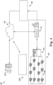
- FIG. 4 is an illustration of a building safety event notification system 400 for use in accordance with one or more embodiments of the present disclosure.
- the building safety event notification system 400 includes an alarm system 402, a central monitoring station having at least one computing device 408, a remote server (e.g., cloud server) 418, and one or more building owner/operator communication applications 420-1 and 420-2.
- a remote server e.g., cloud server
- the alarm system 402 may include a number of event detection devices 406.
- Devices 406 may be detection devices analogous to devices 106 described in connection with Figure 1 .
- Devices 406 may be configured to detect an event within the building, such as a fault in one of the devices 406 or a fire, among other hazardous conditions.
- Devices 406 may then transmit an event alarm signal to a control panel 404.
- Control panel 404 may compile information about the event and/or the detection device 406, such as the type of event alarm signal received, the date and time of receipt, a unique indicator of the device 406 from which it was received, and an indicator of the floor of the building on which the device 406 is located. This information may be transmitted to the computing device 408 and to the remote server 418.
- the alarm system 402 can also include an edge/gateway device 410 through which the information is transmitted to the remote server 418 and to the computing device 408.
- the gateway device 410 acts as a pass-through device for communicating between the alarm system 402 in the building and the central monitoring station 408 and other components of the event notification system 400 that are at remote locations (i.e., outside the building).
- the gateway device 410 can also include edge intelligence functionality that detects when an event alarm condition exists at one alarm system device and collects data from other devices nearby the one indicating the event alarm condition. This information can be beneficial to, for example, provide a fuller picture of the incident.
- the edge intelligence can indicate that there are four smoke detector devices (e.g., devices 406) to the south of the device indicating the alarm that have smoke levels that have slightly increased which indicates that to central monitoring personnel which direction a fire may be spreading and that those detector devices are operational for monitoring the status of the situation.
- devices 406 e.g., devices 406
- the gateway device 410 can also provide other important functions. For example, during commissioning of the alarm system 402, the gateway device 410 can provide a functionality that detects quality of connection of the alarm system devices 406 and the gateway device 410 and can report weak connections to technicians during the commissioning process or during operation of the system. It can identify what connections are problematic and identify the location of the issue, in some instances, to direct the technician to the problem. In some embodiments, the gateway device 410 can also identify trends of problems, for example, where it indicates that every few weeks or months, a problem occurs in a certain area which may prompt a technician to investigate activities in that space that may be triggering the recurrent problem.
- the gateway device 410 of an alarm system 402 at a facility (building) receives event alarm signals from the control panel 404 and reports event alarm signals to one or more central monitoring servers. These servers may be on premise (within the facility) or, as shown in the example of Figure 4 , off premise (at a remote location from the alarm system components including the gateway device).
- the event alarm signals are reported to both the remote server 418 and the appropriate central monitoring station (i.e., the computing device 408).
- information about event alarm signals may be displayed on a graphical user interface of an application on the computing device 408.
- the central monitoring station includes administrators that coordinate activities to respond appropriately based on the type of event that is occurring. For example, a fire event would need a fire-based response that would likely include alerting a fire station to send trucks and contacting medical personnel, if injuries seem likely. For a security issue, security personnel and/or the police would be contacted. For an issue relating to the operation of an alarm system device 406, a technician would be contacted and directed to the location of the faulty alarm system device 406.
- the central monitoring servers are connected back to one or more alarm systems on site and/or remote (cloud) servers, such as alarm system 402 and remote server 418.
- the computing device 408 contains floorplans of each floor of the building, either stored on the memory of the computing device 408 or accessible to the computing device 408 through a software application with executable instructions, for example, stored on the remote server 418. These floorplans include exact locations within each floor of each alarm device 406.
- the computing device 408 can use the unique indicator/identifier of the alarm device 406 and the indicator of the floor on which the alarm device 406 is located to determine the floor on which the event has occurred and generate a floorplan of that floor.
- the floorplan may show the specific location within the floor of the event. This may be done by generating the floorplan for the appropriate floor and highlighting or otherwise indicating a specific region within that floorplan which is monitored by the device 406 reporting the event, thus creating a visual representation of the floor. This visual representation can then be transmitted to the remote server 418.
- Event alarm signals which include all the information complied by the control panel 402, are also transmitted to the remote server 418.
- the remote server 418 may then perform analytics on both the event alarm signals received from the gateway device 410 and the floorplan received from the computing device 408 to generate a visual floor representation.
- This visual floor representation may resemble the floorplan generated by the computing device 408, with the specific location corresponding to the event indicated.
- the visual floor representation may also include any other information received from the event alarm signal, such as the type of event or the time and date at which the event was reported.
- the remote server 418 may transmit this visual floor representation to authorized users through applications, such as applications 420-1 and 420-2.
- applications such as applications 420-1 and 420-2.
- 420-1 may be a mobile application accessible through a mobile device
- 420-2 may be a local or remote application accessible through a personal computer or mobile device.
- the visual floor representation is further described in connection with Figures 5 , 6 , 7 , 8A , and 8B .
- Applications 420-1 and 420-2 may be software applications accessible through a computing device, such as a personal computer or a mobile device, such as a laptop or phone. Applications 420-1 and 420-2 may include executable instructions stored on the memory of the computing device 408 to present the visual floor representation to the user through a graphical user interface. Applications 420-1 and 420-2 may also be remote software applications (e.g., web applications) that include executable instructions stored on the remote server 418 to present the visual floor representation to the user through a graphical user interface of a display device. Such applications may be accessible, for example, through a web browser. The application may be similar to applications used by the computing device 408 to access floorplans stored on the remote server 418.
- a computing device such as a personal computer or a mobile device, such as a laptop or phone.
- Applications 420-1 and 420-2 may include executable instructions stored on the memory of the computing device 408 to present the visual floor representation to the user through a graphical user interface.
- the event notification system 400 can have various connections secured to reduce or eliminate unauthorized connections to the system.
- a security protocol can be utilized wherein the real time status information can only be made available for those parties that enter, for example, a user name and password, authorizing the system to provide such information to a party.
- Such embodiments can also be customizable such that parties with different authorization levels can access different information. These levels and the information types that are made available to each level can be customized, for example, by the building owner/operator or alarm system provider at the time the system is configured or once the system is set up.
- the event notification system 400 can also allow workflow to be defined for different types of alarms, and when progress of one stage is moved to another stage, the graphical user interface can show the current stage details in the user interface. In this way, the building owners/operators can quickly ascertain the status of the event without having to navigate through the mobile application.
- the remote server 418 can also include artificial intelligence functionality that can, for example, inform the receiver of the information that a similar incident happened on a particular date, the period of time that it took to respond to that previous incident, the current time it has taken to respond to the present incident, based on data regarding one or more prior incident's data the estimated time to completely resolve the present incident. This could be achieved, for example, by applying an inference model. This can be beneficial, for instance, by informing the building owner/manager of the timeframe, so that they know how long they have to perform any incident related actions they may have to do.
- FIG 5 is an illustration of a display screen 501 provided on a user interface of a remote or local application (e.g., application 420-2 of Figure 4 ) showing a visual floor representation 517 of a floor on which an event has occurred, generated in accordance with one or more embodiments of the present disclosure.
- the visual floor representation 517 may include a floorplan 519 for the floor corresponding to the alarm device reporting the event. This floorplan 519 may have been accessible through a computing device (e.g., computing device 408 of Figure 4 ) prior to the event alarm signal.
- the visual representation 517 may include an indication of a specific area 521 at which an event has occurred. As described previously, this specific area 521 may be determined by a computing device based on an area monitored by the alarm device 506 reporting the event. Moreover, the remote server (e.g., remote server 418 of Figure 4 ) may further refine this area 521 through inputs and event alarm signals received from other alarm devices 506. For example, if two alarm devices 506 monitor overlapping areas and one alarm device 506 detects an event but the other does not, the remote server may determine that the event has not occurred in the overlapping areas. Thus, the specific area 521 may be reduced to only those areas monitored by the detecting alarm device but not the non-detecting alarm device.
- Text 523 may be shown adjacent to the specific area 521, providing more information about the event alarm signal.
- the visual floor representation 517 may display information about the type of event detected, the time at which the event was detected, or operational statuses or identifiers of one or more event detection alarm devices 506.
- notifications 503 of the event alarm signal(s) received may be displayed along with some or all the information transmitted within that signal.
- multiple regions may be indicated, not just region 521 corresponding to the first event.
- a second visual floor representation may open in a separate window of the display, as described in further detail in connection with Figure 8A .
- the visual floor representation 517 may be updated continuously as events are resolved. For example, if a detection alarm device detects a resolution of an event, or if the user receives a notification of the resolution through the application, the visual floor representation may be updated to no longer show the specific area of that event.
- the visual floor representation 517 may also include indicators of exits 525 so that the user can easily see possible escape routes.
- Figure 6 is an illustration of a display screen 601 provided on a user interface of a mobile device (e.g., mobile application 420-1 of Figure 4 of a mobile device) showing a visual floor representation 617 of a floor on which an event has occurred, generated in accordance with one or more embodiments of the present disclosure.
- Figure 6 is an illustration of a version of the display screen 501 of Figure 5 , adapted for a mobile device.
- display screen 601 may display a visual floor representation 617 of event signals received from a gateway device, with the specific locations 621 of such events indicated (e.g., by highlighting the specific locations 621).
- embodiments of the present disclosure allow for ease in viewing and responding to event notifications by providing the user with a highly effective representation (517 and 617) of the specific event location within the floor on which the event occurred. Once the events have been resolved, these visual representations 517 and 617 may be stored within the applications.
- the same application may be used to view events in multiple buildings.
- the user may have the option to make a selection 627 of buildings to which they are given access.
- Figure 7 is an illustration of a display screen 701 provided on a user interface of a mobile device, showing an electronic mail notification of an event of a building safety system, generated in accordance with one or more embodiments of the present disclosure.
- systems e.g., system 400
- a remote server e.g., remote server 4108
- a software application e.g., applications 420-1 and 420-2
- This notification 729 may include a textual notification 703 including various types of information, such as a time and date of the detection of the event, an identification number corresponding to the event detection device, an event detection device type (e.g., smoke alarm), and/or a network name which the device is a part of, among other suitable information.
- the notification 729 may also include a visual floor representation 717 generated by the remote server.
- This visual representation 717 may include an indicator 721 of a specific location of an event. This indicator 721 may be, for example, a circle surrounding the alarm device 706 which detected the event.
- Figure 8A is an illustration of a display screen 801 provided on a user interface of an application (e.g., application 420-2 of Figure 4 ), showing visual floor representations 817-1 and 817-2 of one or more floors 819-1 and 819-2, generated in accordance with one or more embodiments of the present disclosure.
- the graphical user interface may have two or more windows 831-1 and 831-2 open at one time, even if only one window (e.g., a front window 831-1) is visible on the display screen 801.
- a building safety system may detect an event on a certain floor 819-2 of the building while the visual floor representation 817-1 corresponding to a different floor 819-1 is open on the display screen 801.
- the application may be configured to capture an image of the visual floor representation 817-2 of the floor 819-2 on which the most recent event is detected and transmit a notification (e.g., notification 729 of Figure 7 ) to pre-determined users without changing the display screen 801, since the second visual floor representation 817-2 will be displayed in a window 831-2 behind the first generated window 831-1.
- a notification e.g., notification 729 of Figure 7
- users can continue to use the application to view information about the floor 819-1 on the front window 831-1 uninterrupted while all of the necessary users are immediately notified of the event occurring on the other floor 819-2.
- these users will receive a visual floor representation 717 that may eliminate their need to access another application to access the event information.
- the visual representation 817-1 corresponding to that floor may simply be updated to add an indicator for the specific location of the additional event.
- Figure 8B is an illustration of a display screen 801 provided on the user interface of the application of Figure 8A , showing a visual floor representation 817-2 of one of the floors 819-2 on which events have occurred, generated in accordance with one or more embodiments of the present disclosure.
- a user may choose to open a window 831-2 corresponding to a newly received event alarm signal. This window 831-2 will show a visual floor representation 817-2.
- the window 831-2 will also show a real-time queue 833 of event alarm signals received by the system, which may be continuously updated to show only events that have not been resolved and corresponding floors for each event.
- the user of the application may access the visual floor representation, which includes the indication of the specific location of the event, as described in the foregoing, by selecting one of these event alarm signals in the queue 833.
- the user may view and interact with various visual representations of different floors 819 of the building through a panel 835.
- Each of these computing devices includes a processor and memory which can function as described below. Also described below are other items that may be provided on such computing devices, such as user input and output components.
- the memory can be any type of storage medium that can be accessed by the processor to perform various examples of the present disclosure.
- the memory can be a non-transitory computer readable medium having computer readable instructions (e.g., executable instructions/computer program instructions) stored thereon that are executable by the processor in accordance with the present disclosure.
- the memory can be volatile or nonvolatile memory.
- the memory can also be removable (e.g., portable) memory, or non-removable (e.g., internal) memory.
- the memory can be random access memory (RAM) (e.g., dynamic random access memory (DRAM) and/or phase change random access memory (PCRAM)), read-only memory (ROM) (e.g., electrically erasable programmable read-only memory (EEPROM) and/or compact-disc read-only memory (CD-ROM)), flash memory, a laser disc, a digital versatile disc (DVD) or other optical storage, and/or a magnetic medium such as magnetic cassettes, tapes, or disks, among other types of memory.
- RAM random access memory
- DRAM dynamic random access memory
- PCRAM phase change random access memory
- ROM read-only memory
- EEPROM electrically erasable programmable read-only memory
- CD-ROM compact-disc read-only memory
- flash memory a laser disc, a digital versatile disc
- memory is illustrated as being located within the computing device, embodiments of the present disclosure are not so limited.
- memory can also be located internal to another computing resource (e.g., enabling computer readable instructions to be downloaded over the Internet or another wired or wireless connection).
- a computing device can also include a user interface.
- the user interface can display the embodiments illustrated in Figures 2 , 3 , 5 , 8A , and 8B .
- a user e.g., operator of computing device can interact with the computing device via the user interface.
- the user interface can provide (e.g., display and/or present) information to the user of the computing device, and/or receive information from (e.g., input by) the user of computing device.
- user interface can be a graphical user interface (GUI) that can provide and/or receive information to and/or from the user of the computing device.
- GUI graphical user interface
- the display can be, for instance, a touch-screen (e.g., the GUI can include touch-screen capabilities).
- a display can include a television, computer monitor, mobile device screen, other type of display device, or any combination thereof, connected to mobile device and configured to receive a video signal output from the mobile device.
- the user interface can include a keyboard and/or mouse the user can use to input information into the computing device.
- the user interface can include a keyboard and/or mouse the user can use to input information into the computing device.
- Embodiments of the present disclosure are not limited to a particular type(s) of user interface.
- User interface can be localized to any language.
- user interface can utilize in any language, such as English, Spanish, German, French, Mandarin, Arabic, Japanese, Hindi, etc.
Landscapes
- Engineering & Computer Science (AREA)
- Physics & Mathematics (AREA)
- General Physics & Mathematics (AREA)
- Business, Economics & Management (AREA)
- Emergency Management (AREA)
- Computing Systems (AREA)
- Geometry (AREA)
- Theoretical Computer Science (AREA)
- Computer Hardware Design (AREA)
- Computer Networks & Wireless Communication (AREA)
- Structural Engineering (AREA)
- Civil Engineering (AREA)
- Architecture (AREA)
- Computational Mathematics (AREA)
- Mathematical Analysis (AREA)
- Mathematical Optimization (AREA)
- Pure & Applied Mathematics (AREA)
- Evolutionary Computation (AREA)
- General Engineering & Computer Science (AREA)
- Electromagnetism (AREA)
- Environmental & Geological Engineering (AREA)
- General Health & Medical Sciences (AREA)
- Toxicology (AREA)
- Health & Medical Sciences (AREA)
- Radar, Positioning & Navigation (AREA)
- Remote Sensing (AREA)
- Computer Security & Cryptography (AREA)
- Accounting & Taxation (AREA)
- Development Economics (AREA)
- Economics (AREA)
- General Business, Economics & Management (AREA)
- Alarm Systems (AREA)
- Telephonic Communication Services (AREA)
Applications Claiming Priority (2)
| Application Number | Priority Date | Filing Date | Title |
|---|---|---|---|
| US202163175248P | 2021-04-15 | 2021-04-15 | |
| EP22167822.0A EP4075401B1 (de) | 2021-04-15 | 2022-04-12 | Bestimmung und benachrichtigung eines ortes eines gebäudesicherheitssystems |
Related Parent Applications (1)
| Application Number | Title | Priority Date | Filing Date |
|---|---|---|---|
| EP22167822.0A Division EP4075401B1 (de) | 2021-04-15 | 2022-04-12 | Bestimmung und benachrichtigung eines ortes eines gebäudesicherheitssystems |
Publications (2)
| Publication Number | Publication Date |
|---|---|
| EP4475104A2 true EP4475104A2 (de) | 2024-12-11 |
| EP4475104A3 EP4475104A3 (de) | 2025-03-12 |
Family
ID=81307300
Family Applications (2)
| Application Number | Title | Priority Date | Filing Date |
|---|---|---|---|
| EP22167822.0A Active EP4075401B1 (de) | 2021-04-15 | 2022-04-12 | Bestimmung und benachrichtigung eines ortes eines gebäudesicherheitssystems |
| EP24209297.1A Pending EP4475104A3 (de) | 2021-04-15 | 2022-04-12 | Bestimmung und meldung eines standorts eines gebäudesicherheitssystemereignisses |
Family Applications Before (1)
| Application Number | Title | Priority Date | Filing Date |
|---|---|---|---|
| EP22167822.0A Active EP4075401B1 (de) | 2021-04-15 | 2022-04-12 | Bestimmung und benachrichtigung eines ortes eines gebäudesicherheitssystems |
Country Status (3)
| Country | Link |
|---|---|
| US (3) | US11798387B2 (de) |
| EP (2) | EP4075401B1 (de) |
| CN (1) | CN115223348B (de) |
Families Citing this family (9)
| Publication number | Priority date | Publication date | Assignee | Title |
|---|---|---|---|---|
| CN111402540B (zh) * | 2020-02-25 | 2021-08-24 | 王勇强 | 吸气式感烟火灾探测装置、方法及设备 |
| EP4075401B1 (de) * | 2021-04-15 | 2024-10-30 | Honeywell International Inc. | Bestimmung und benachrichtigung eines ortes eines gebäudesicherheitssystems |
| US12523975B2 (en) | 2021-06-08 | 2026-01-13 | Tyco Fire & Security Gmbh | Building management system with intelligent visualization |
| US11722560B2 (en) * | 2021-10-26 | 2023-08-08 | Vmware, Inc. | Reconciling host cluster membership during recovery |
| CN114971409B (zh) * | 2022-06-28 | 2024-06-21 | 成都秦川物联网科技股份有限公司 | 一种基于物联网的智慧城市火灾监控预警方法及系统 |
| US12523999B2 (en) | 2022-10-20 | 2026-01-13 | Tyco Fire & Security Gmbh | Building management system with intelligent fault visualization |
| US20240194054A1 (en) * | 2022-12-07 | 2024-06-13 | Johnson Controls Tyco IP Holdings LLP | Building management system with intelligent visualization for fire suppression, fire prevention, and security integration |
| US20240219182A1 (en) * | 2023-01-04 | 2024-07-04 | Honeywell International Inc. | Extraction of routing card information of an event system |
| US20260052303A1 (en) * | 2024-08-19 | 2026-02-19 | Honeywell International Inc. | Automated association of sensors and cameras in a security system |
Family Cites Families (27)
| Publication number | Priority date | Publication date | Assignee | Title |
|---|---|---|---|---|
| US5061916A (en) | 1990-05-29 | 1991-10-29 | Barber-Colman Company | Event driven remote graphical reporting of building automation system parameters |
| US20070008099A1 (en) | 1999-09-01 | 2007-01-11 | Nettalon Security Systems, Inc. | Method and apparatus for remotely monitoring a site |
| JP4723813B2 (ja) | 2004-02-06 | 2011-07-13 | 富士通株式会社 | 携帯端末の緊急メール通知制御方法及びシステム |
| US20160065414A1 (en) | 2013-06-27 | 2016-03-03 | Ken Sundermeyer | Control system user interface |
| KR20050100491A (ko) | 2004-04-14 | 2005-10-19 | 주식회사 팬택앤큐리텔 | 온라인망을 기반으로 하는 위치 추적/보고 시스템 및 방법 |
| TW200726257A (en) * | 2005-12-20 | 2007-07-01 | Taiwan Secom Co Ltd | Method for displaying and updating monitor plan drawing |
| JP5876371B2 (ja) | 2012-04-27 | 2016-03-02 | 京セラ株式会社 | 携帯電子機器、通信プログラム及び通信システム |
| CA3246645A1 (en) | 2012-11-12 | 2025-06-06 | Sielox, Llc | Emergency notification system and methods |
| US9666042B2 (en) | 2012-12-13 | 2017-05-30 | Oneevent Technologies, Inc. | Enhanced emergency detection system |
| US10437448B2 (en) * | 2014-07-08 | 2019-10-08 | Honeywell International Inc. | System and method for auto-configuration of devices in building information model |
| CN107667552B (zh) * | 2015-03-24 | 2021-11-09 | 开利公司 | 分布式装置的基于楼层平面图的学习和注册方法 |
| CN107660299B (zh) * | 2015-03-24 | 2021-02-26 | 开利公司 | 建筑物系统的基于楼层平面图的规划 |
| US20190266860A1 (en) * | 2016-07-26 | 2019-08-29 | Carrier Corporation | Building evacuation management system |
| US10269236B2 (en) * | 2016-09-06 | 2019-04-23 | Honeywell International Inc. | Systems and methods for generating a graphical representation of a fire system network and identifying network information for predicting network faults |
| KR101844472B1 (ko) | 2017-05-10 | 2018-04-02 | 김경수 | 원격 방재 시스템 |
| US10922941B2 (en) | 2017-09-13 | 2021-02-16 | 4Morr Enterprises IP, LLC | System and method for detecting smoke using a photoelectric sensor |
| US10872518B2 (en) | 2017-11-29 | 2020-12-22 | Alertpoint, LLC | Alerthub system with two touch badge |
| US10255780B1 (en) | 2018-05-29 | 2019-04-09 | David Wittenberg | System and method for detecting and mapping progression of a fire event |
| CN110956563A (zh) * | 2018-09-27 | 2020-04-03 | 永扬消防安全设备股份有限公司 | 消防信息整合系统 |
| JP7288785B2 (ja) | 2019-03-29 | 2023-06-08 | ホーチキ株式会社 | 防災システム |
| CN110400437A (zh) * | 2019-07-05 | 2019-11-01 | 同济大学 | 基于大数据处理的火灾监控报警与逃生指示一体化系统 |
| US20210073430A1 (en) * | 2019-09-06 | 2021-03-11 | BeamUp, Ltd. | Structural design systems and methods for optimizing equipment selection in floorplans using modeling and simulation |
| US11531789B1 (en) * | 2019-09-27 | 2022-12-20 | Amazon Technologies, Inc. | Floor plan generation for device visualization and use |
| US11570607B2 (en) * | 2020-04-03 | 2023-01-31 | Rapidsos, Inc. | Systems and methods for identifying and activating emergency response assets |
| US20220318441A1 (en) * | 2021-03-31 | 2022-10-06 | SY Interiors Pvt. Ltd | Methods and systems for provisioning a virtual experience of a building |
| EP4075401B1 (de) * | 2021-04-15 | 2024-10-30 | Honeywell International Inc. | Bestimmung und benachrichtigung eines ortes eines gebäudesicherheitssystems |
| US12547787B2 (en) * | 2022-04-08 | 2026-02-10 | Honeywell International Inc. | Fire system floor plan layout generation |
-
2022
- 2022-04-12 EP EP22167822.0A patent/EP4075401B1/de active Active
- 2022-04-12 EP EP24209297.1A patent/EP4475104A3/de active Pending
- 2022-04-12 US US17/718,595 patent/US11798387B2/en active Active
- 2022-04-15 CN CN202210413890.3A patent/CN115223348B/zh active Active
-
2023
- 2023-10-24 US US18/383,089 patent/US12254753B2/en active Active
-
2025
- 2025-03-17 US US19/081,328 patent/US20250246055A1/en active Pending
Also Published As
| Publication number | Publication date |
|---|---|
| EP4475104A3 (de) | 2025-03-12 |
| EP4075401B1 (de) | 2024-10-30 |
| EP4075401A1 (de) | 2022-10-19 |
| CN115223348A (zh) | 2022-10-21 |
| US20220335799A1 (en) | 2022-10-20 |
| US20240105038A1 (en) | 2024-03-28 |
| CN115223348B (zh) | 2024-12-27 |
| US12254753B2 (en) | 2025-03-18 |
| US11798387B2 (en) | 2023-10-24 |
| US20250246055A1 (en) | 2025-07-31 |
Similar Documents
| Publication | Publication Date | Title |
|---|---|---|
| EP4475104A2 (de) | Bestimmung und meldung eines standorts eines gebäudesicherheitssystemereignisses | |
| US20250371968A1 (en) | Live status notification of response personnel actions to building owner/operators | |
| US12293651B2 (en) | Self-testing fire sensing device for confirming a fire | |
| US12400539B2 (en) | Aspirating smoke detector device operational analysis | |
| US9633533B2 (en) | System and method for interacting with digital video recorders through networking applications | |
| CN114863660A (zh) | 使用移动设备来发起和监测报警系统的自测试 | |
| EP4386702A1 (de) | Alarmsystemdetektorgeofencing | |
| EP4310810B1 (de) | Durchführung einer selbstreinigung einer branderfassungsvorrichtung | |
| US11720459B2 (en) | Event input device testing | |
| EP4170620A1 (de) | Einleitung einer brandreaktion bei einer selbsttestenden branderfassungsvorrichtung | |
| US12597337B2 (en) | Event sensing device | |
| KR102606850B1 (ko) | 재난대응장치 및 방법 | |
| CN117423223A (zh) | 向第一响应者提供建筑物目的地的实况情境信息以用于增强的公共安全操作的系统、方法和过程 |
Legal Events
| Date | Code | Title | Description |
|---|---|---|---|
| PUAI | Public reference made under article 153(3) epc to a published international application that has entered the european phase |
Free format text: ORIGINAL CODE: 0009012 |
|
| STAA | Information on the status of an ep patent application or granted ep patent |
Free format text: STATUS: THE APPLICATION HAS BEEN PUBLISHED |
|
| AC | Divisional application: reference to earlier application |
Ref document number: 4075401 Country of ref document: EP Kind code of ref document: P |
|
| AK | Designated contracting states |
Kind code of ref document: A2 Designated state(s): AL AT BE BG CH CY CZ DE DK EE ES FI FR GB GR HR HU IE IS IT LI LT LU LV MC MK MT NL NO PL PT RO RS SE SI SK SM TR |
|
| REG | Reference to a national code |
Ref country code: DE Ref legal event code: R079 Free format text: PREVIOUS MAIN CLASS: G08B0025000000 Ipc: G08B0017000000 |
|
| PUAL | Search report despatched |
Free format text: ORIGINAL CODE: 0009013 |
|
| AK | Designated contracting states |
Kind code of ref document: A3 Designated state(s): AL AT BE BG CH CY CZ DE DK EE ES FI FR GB GR HR HU IE IS IT LI LT LU LV MC MK MT NL NO PL PT RO RS SE SI SK SM TR |
|
| RIC1 | Information provided on ipc code assigned before grant |
Ipc: G08B 25/00 20060101ALI20250205BHEP Ipc: G08B 17/00 20060101AFI20250205BHEP |
|
| STAA | Information on the status of an ep patent application or granted ep patent |
Free format text: STATUS: REQUEST FOR EXAMINATION WAS MADE |
|
| 17P | Request for examination filed |
Effective date: 20250829 |
|
| STAA | Information on the status of an ep patent application or granted ep patent |
Free format text: STATUS: EXAMINATION IS IN PROGRESS |
|
| 17Q | First examination report despatched |
Effective date: 20251209 |