EP4474824A1 - Automated analyzing device - Google Patents
Automated analyzing device Download PDFInfo
- Publication number
- EP4474824A1 EP4474824A1 EP22924200.3A EP22924200A EP4474824A1 EP 4474824 A1 EP4474824 A1 EP 4474824A1 EP 22924200 A EP22924200 A EP 22924200A EP 4474824 A1 EP4474824 A1 EP 4474824A1
- Authority
- EP
- European Patent Office
- Prior art keywords
- unit
- harmonic component
- stirring
- ultrasonic wave
- waveform
- Prior art date
- Legal status (The legal status is an assumption and is not a legal conclusion. Google has not performed a legal analysis and makes no representation as to the accuracy of the status listed.)
- Pending
Links
Images


Classifications
-
- G—PHYSICS
- G01—MEASURING; TESTING
- G01N—INVESTIGATING OR ANALYSING MATERIALS BY DETERMINING THEIR CHEMICAL OR PHYSICAL PROPERTIES
- G01N35/00—Automatic analysis not limited to methods or materials provided for in any single one of groups G01N1/00 - G01N33/00; Handling materials therefor
- G01N35/00584—Control arrangements for automatic analysers
-
- G—PHYSICS
- G01—MEASURING; TESTING
- G01N—INVESTIGATING OR ANALYSING MATERIALS BY DETERMINING THEIR CHEMICAL OR PHYSICAL PROPERTIES
- G01N35/00—Automatic analysis not limited to methods or materials provided for in any single one of groups G01N1/00 - G01N33/00; Handling materials therefor
- G01N35/00584—Control arrangements for automatic analysers
- G01N35/00594—Quality control, including calibration or testing of components of the analyser
- G01N35/00613—Quality control
- G01N35/00623—Quality control of instruments
-
- B—PERFORMING OPERATIONS; TRANSPORTING
- B01—PHYSICAL OR CHEMICAL PROCESSES OR APPARATUS IN GENERAL
- B01F—MIXING, e.g. DISSOLVING, EMULSIFYING OR DISPERSING
- B01F31/00—Mixers with shaking, oscillating, or vibrating mechanisms
- B01F31/80—Mixing by means of high-frequency vibrations above one kHz, e.g. ultrasonic vibrations
- B01F31/86—Mixing by means of high-frequency vibrations above one kHz, e.g. ultrasonic vibrations with vibration of the receptacle or part of it
-
- B—PERFORMING OPERATIONS; TRANSPORTING
- B01—PHYSICAL OR CHEMICAL PROCESSES OR APPARATUS IN GENERAL
- B01F—MIXING, e.g. DISSOLVING, EMULSIFYING OR DISPERSING
- B01F31/00—Mixers with shaking, oscillating, or vibrating mechanisms
- B01F31/80—Mixing by means of high-frequency vibrations above one kHz, e.g. ultrasonic vibrations
- B01F31/87—Mixing by means of high-frequency vibrations above one kHz, e.g. ultrasonic vibrations transmitting the vibratory energy by means of a fluid, e.g. by means of air shock waves
-
- G—PHYSICS
- G01—MEASURING; TESTING
- G01N—INVESTIGATING OR ANALYSING MATERIALS BY DETERMINING THEIR CHEMICAL OR PHYSICAL PROPERTIES
- G01N35/00—Automatic analysis not limited to methods or materials provided for in any single one of groups G01N1/00 - G01N33/00; Handling materials therefor
- G01N35/00584—Control arrangements for automatic analysers
- G01N35/00722—Communications; Identification
-
- G—PHYSICS
- G01—MEASURING; TESTING
- G01N—INVESTIGATING OR ANALYSING MATERIALS BY DETERMINING THEIR CHEMICAL OR PHYSICAL PROPERTIES
- G01N35/00—Automatic analysis not limited to methods or materials provided for in any single one of groups G01N1/00 - G01N33/00; Handling materials therefor
- G01N35/02—Automatic analysis not limited to methods or materials provided for in any single one of groups G01N1/00 - G01N33/00; Handling materials therefor using a plurality of sample containers moved by a conveyor system past one or more treatment or analysis stations
- G01N35/025—Automatic analysis not limited to methods or materials provided for in any single one of groups G01N1/00 - G01N33/00; Handling materials therefor using a plurality of sample containers moved by a conveyor system past one or more treatment or analysis stations having a carousel or turntable for reaction cells or cuvettes
-
- G—PHYSICS
- G01—MEASURING; TESTING
- G01N—INVESTIGATING OR ANALYSING MATERIALS BY DETERMINING THEIR CHEMICAL OR PHYSICAL PROPERTIES
- G01N35/00—Automatic analysis not limited to methods or materials provided for in any single one of groups G01N1/00 - G01N33/00; Handling materials therefor
- G01N2035/00465—Separating and mixing arrangements
- G01N2035/00524—Mixing by agitating sample carrier
-
- G—PHYSICS
- G01—MEASURING; TESTING
- G01N—INVESTIGATING OR ANALYSING MATERIALS BY DETERMINING THEIR CHEMICAL OR PHYSICAL PROPERTIES
- G01N35/00—Automatic analysis not limited to methods or materials provided for in any single one of groups G01N1/00 - G01N33/00; Handling materials therefor
- G01N2035/00465—Separating and mixing arrangements
- G01N2035/00534—Mixing by a special element, e.g. stirrer
- G01N2035/00554—Mixing by a special element, e.g. stirrer using ultrasound
-
- G—PHYSICS
- G01—MEASURING; TESTING
- G01N—INVESTIGATING OR ANALYSING MATERIALS BY DETERMINING THEIR CHEMICAL OR PHYSICAL PROPERTIES
- G01N35/00—Automatic analysis not limited to methods or materials provided for in any single one of groups G01N1/00 - G01N33/00; Handling materials therefor
- G01N35/00584—Control arrangements for automatic analysers
- G01N35/00722—Communications; Identification
- G01N2035/00891—Displaying information to the operator
- G01N2035/009—Displaying information to the operator alarms, e.g. audible
Definitions
- the present invention relates to an automatic analyzer.
- An automatic analyzer performs qualitative and quantitative analysis by adding, stirring, and reacting a reagent that specifically reacts with a specific component contained in a biological sample such as blood or urine, and measuring absorbance or luminescence amount of a reaction solution.
- a stirring unit of the automatic analyzer stirring using an ultrasonic wave is proposed in order to prevent a phenomenon called carry-over that affects a next analysis result by continuous stirring.
- PTL 1 discloses an automatic analyzer that detects a waveform of a voltage generated by an ultrasonic wave generation source, normalizes an amplitude from a maximum value and a minimum value of the detected waveform, and determines whether a stirring state by the ultrasonic wave generation source is good or poor by comparison with a normal state.
- the invention has been made to solve such a problem, and an object of the invention is to provide a highly reliable automatic analyzer capable of determining a stirring state with high accuracy regardless of a difference in a physical property due to a material or a structure of an ultrasonic wave generation source.
- an automatic analyzer including: a stirring unit configured to stir a sample and a reagent; an analysis unit configured to perform component analysis of the sample using a reaction solution of the sample and the reagent; and a control unit configured to control the stirring unit and the analysis unit.
- the stirring unit includes an ultrasonic wave generation source that generates an ultrasonic wave, a drive circuit that drives the ultrasonic wave generation source, and a waveform detection unit that detects an electric waveform output from the ultrasonic wave generation source in accordance with driving, the stirring unit further includes a harmonic component extraction unit that extracts a harmonic component from the electric waveform detected by the waveform detection unit, and the control unit determines whether a stirring state of the stirring unit is good or poor based on a signal intensity of the harmonic component extracted by the harmonic component extraction unit.
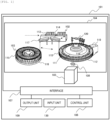
- FIG. 1 is an overall schematic configuration diagram of an automatic analyzer 101 according to the embodiment.
- the automatic analyzer 101 analyzes a specific component in a sample by reacting a sample 102 with a reagent 103, and includes an analysis unit 104, a stirring unit 105, a control unit 106, an output unit 109, an input unit 130, and an interface 107.
- the analysis unit 104 includes a sample aliquoting mechanism 114 that dispenses the sample 102 in a sample container 113 into a reaction vessel 110, a reagent disk 116 that stores a reagent container 115 containing the reagent 103, a reagent aliquoting mechanism 117 that dispenses the reagent 103 into the reaction vessel 110, a light source 118 for irradiating a reaction solution obtained by reacting the sample 102 with the reagent 103 in the reaction vessel 110 with light, a spectrophotometer 119 that measures absorbance of the reaction solution, and a cleaning mechanism 120 that cleans the reaction vessel 110 after completion of the measurement.
- a sample aliquoting mechanism 114 that dispenses the sample 102 in a sample container 113 into a reaction vessel 110
- a reagent disk 116 that stores a reagent container 115 containing the reagent 103
- a reagent aliquoting mechanism 117 that dispenses the
- the stirring unit 105 stirs the sample 102 and the reagent 103 dispensed into the reaction vessel 110 by an ultrasonic wave 108.
- the control unit 106 performs good-or-poor determination for a stirring state of the stirring unit 105 and performs an automatic adjustment as described later.
- the output unit 109 displays a result of the good-or-poor determination or the automatic adjustment, an alarm of an automatic adjustment error, and the like, and is, for example, a display.
- the input unit 130 is used when a user inputs operation information and the like, and is, for example, a keyboard.
- the interface 107 connects each mechanism of the analysis unit 104 to the control unit 106, the output unit 109, and the input unit 130, and exchanges signals.
- a biochemical automatic analyzer that obtains a concentration of a predetermined component using the spectrophotometer 119 that measures absorbance will be described as an example, whereas the technique disclosed in the embodiment to be described later may be used for an immune automatic analyzer or a coagulation automatic analyzer that measures a sample using another spectrophotometer.
- Component analysis of the sample 102 in the automatic analyzer 101 is mainly performed in the following procedure.
- the control unit 106 automatically creates an analysis program and controls each unit as follows based on the program.
- a belt or a motor carries the sample container 113 containing the sample 102 to a sample aliquoting position.
- the sample aliquoting mechanism 114 aspirates the sample 102 from the sample container 113 and dispenses the sample 102 into the reaction vessel 110 placed on a reaction disk 111.
- the reaction vessel 110 into which the sample 102 is dispensed moves to a reagent aliquoting position.
- the reagent aliquoting mechanism 117 aspirates the reagent 103 from the reagent container 115 and dispenses the reagent 103 into the reaction vessel 110 into which the sample 102 is dispensed.
- the reaction vessel 110 into which the sample 102 and the reagent 103 are dispensed moves to a stirring position by the rotation of the reaction disk 111.
- the stirring unit 105 stirs the sample 102 and the reagent 103 in the reaction vessel 110 by the stirring unit 105.
- the reaction disk 111 further rotates, and the reaction vessel 110 moves to an absorbance measurement position.
- the spectrophotometer 119 measures the absorbance during or after the reaction between the sample 102 and the reagent 103.
- the reaction disk 111 further rotates, and the reaction vessel 110 moves to a cleaning position.
- the cleaning mechanism 120 aspirates a reaction solution in the reaction vessel 110 to clean the reaction vessel 110.
- component analysis of one sample is executed by a series of operations as described above, the same component analysis is executed in parallel as batch processing for a plurality of other samples.
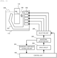
- FIG. 2 is a configuration diagram showing details of a portion related to the stirring unit 105.
- the stirring unit 105 includes, in addition to ultrasonic wave generation sources 202, a reflection plate 207, a selection unit 205, a drive circuit 204, a waveform detection unit 203, and a harmonic component extraction unit 201.
- the ultrasonic wave generation sources 202 are installed in a reaction tank 112 filled with a heat insulating medium 208 and generates the ultrasonic wave 108.
- the ultrasonic wave 108 propagates through the heat insulating medium 208, enters the reaction vessel 110 from a side surface of the reaction vessel 110 disposed to be immersed in the heat insulating medium 208, and reaches a liquid containing a sample and a reagent (hereinafter, referred to as a "stirred liquid 206”), thereby stirring the stirred liquid 206.
- a piezoelectric element which is an element utilizing a piezoelectric effect is used.
- a piezoelectric ceramic element mainly made of lead zirconate titanate (PZT) is preferable because it has a simple configuration and high sensitivity and can improve various characteristics by adding additives.
- the piezoelectric effect refers to a phenomenon in which when a voltage is applied to a piezoelectric element, polarization in which surface charge is biased occurs due to a change in an internal crystal structure, and the piezoelectric element mechanically expands or contracts depending on a state of the polarization. Since the polarization and mechanical expansion and contraction of the piezoelectric element follow the applied voltage, the ultrasonic wave propagates through a medium in contact with the piezoelectric element by setting a frequency of the applied voltage to about 20 kHz or more.
- a material that utilizes a magnetostrictive effect may be used.
- the magnetostrictive effect is a phenomenon in which a magnetic body expands and contracts due to a magnetic field generated by passing a current through coils wound around the magnetic body.
- a method using the magnetostrictive effect has an advantage that a high voltage is not required due to current driving, but has a disadvantage that a large space is required due to presence of the magnetic body or the coils.
- a plurality of the ultrasonic wave generation sources 202 are disposed in an array in a height direction, and each of the ultrasonic wave generation sources 202 is provided with an electrode.
- a surface of each electrode on a side in contact with the heat insulating medium 208 is grounded as a GND electrode, or an insulating layer is provided.
- the reflection plate 207 is provided to extend to an opposite side from the ultrasonic wave generation source 202 with respect to the reaction vessel 110, and reflects the ultrasonic wave 108 transmitted through the reaction vessel 110 and the like to irradiate the reaction vessel 110 again.
- the ultrasonic wave 108 reflected by the reflection plate 207 enters the reaction vessel 110 from the side surface of the reaction vessel 110 and reaches the stirred liquid 206, thereby stirring the stirred liquid 206.
- the reflection plate 207 has an upper inclination and a lower inclination so as to be refracted.
- the upper inclination serves to reflect the transmitted ultrasonic wave 108 downward and emit the ultrasonic wave 108 toward the reaction vessel 110 again.
- the lower inclination serves to release air bubbles unintentionally generated by stirring of the stirred liquid 206 toward a liquid surface of the stirred liquid 206.
- the selection unit 205 switches the electrode to be driven among the electrodes provided in the plurality of ultrasonic wave generation sources 202 as described above. Therefore, even if a liquid amount of the stirred liquid 206 is different for each analysis item, the selection unit 205 selects and drives one or a plurality of electrodes corresponding to the liquid amount, and thus it is possible to irradiate an appropriate height region with the ultrasonic wave 108.
- a relay or a multiplexer is used as the selection unit 205.
- the drive circuit 204 is controlled under a driving condition set by the control unit 106, and applies a voltage to the electrode selected by the selection unit 205 to drive the corresponding ultrasonic wave generation source 202.
- the waveform detection unit 203 detects an electric waveform output from the electrode of the ultrasonic wave generation source 202 in accordance with driving.
- the electric waveform detected by the waveform detection unit 203 may be any of a current waveform, an output waveform, and an instantaneous power waveform.
- the current waveform is detected as a current flowing in accordance with a magnetic field generated in an electric circuit using coils or a Hall element.
- the waveform detection unit 203 detects the current waveform, there is an advantage that it can be electrically insulated from the drive circuit 204, but there is a disadvantage that accuracy deteriorates, as compared with the case of detecting the voltage waveform.
- the instantaneous power waveform can be detected by providing a circuit having a function of a digital multiplier or an analog multiplier in addition to the detection of the current waveform and the voltage waveform.
- the waveform detection unit 203 detects the instantaneous power waveform, there is an advantage that the power in consideration of both the voltage and the current can be detected, but there is a disadvantage that it takes a time longer than the detection of only the voltage or the current.
- the output waveform in accordance with the driving of the ultrasonic wave generation source 202 may be detected using a sound pressure detection sensor or an acceleration sensor.
- the harmonic component extraction unit 201 decomposes the electric waveform detected by the waveform detection unit 203 for each frequency component, and extracts a harmonic component.
- the harmonic means a wave having a frequency component that is an integral multiple of a frequency of a fundamental wave with respect to a fundamental wave of an electric waveform.
- units for implementing the function of decomposing the electric waveform for each frequency component for example, there is a fast Fourier transform (FFT) analyzer and a lockin amplifier using phase-sensitive detection.
- FFT fast Fourier transform
- Information on a signal intensity of the harmonic component extracted by the harmonic component extraction unit 201 is fed back to the control unit 106, and the control unit 106 determines whether the stirring state of the stirring unit 105 is good or poor based on the information.
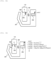
- FIG. 3A is a conceptual diagram showing the stirring state when the piezoelectric element performs an expansion and contraction movement only by a fundamental wave
- FIG. 3B is a conceptual diagram showing the stirring state when the piezoelectric element performs the expansion and contraction movement by including harmonics.
- the ultrasonic wave 108 is also a wave of only the fundamental wave. Displacement information of the ultrasonic wave 108 at this time propagates through the stirred liquid 206 as a medium, and a water molecule 303 in the reaction vessel 110 performs only a small reciprocating movement as indicated by an arrow G of a wavelength of a vertical wave. That is, when the expansion and contraction movement of the piezoelectric element includes only the fundamental wave, a sufficient stirring flow is not generated in the reaction vessel 110.
- the ultrasonic wave 108 when the piezoelectric element performs the expansion and contraction movement by including the harmonics, the ultrasonic wave 108 also becomes a wave including the harmonics. Focusing on each frequency component of the harmonics, odd-order harmonics are represented by a sum of periodic functions, whereas even-order harmonics include a DC component. Therefore, when the displacement information of the ultrasonic wave 108 propagates, the water molecule 303 in the reaction vessel 110 moves in a certain direction as indicated by an arrow H. That is, the harmonic component included in the expansion and contraction movement of the piezoelectric element contributes to generation of the stirring flow in the reaction vessel 110.
- the stirring unit 105 can stir the stirred liquid 206 in a non-contact manner by intermittently burst-emitting the ultrasonic wave 108 having the DC component.
- a duty ratio and an irradiation frequency of ultrasonic wave irradiation are preferably set based on dimensions of the reaction vessel 110.
- a relationship between the voltage applied to the piezoelectric element and an amount of expansion and contraction (amount of polarization) of the piezoelectric element will be described.
- a relationship between an amount of polarization P and an applied voltage V i has a predetermined polarization characteristic 405 for each physical property of the piezoelectric element. Since the polarization characteristic 405 of a general piezoelectric element has hysteresis, a hysteresis characteristic will be specifically described.
- the polarization When no voltage is applied to the piezoelectric element, the polarization is oriented in various directions in order to stabilize a state within a crystal.
- the polarization when a voltage is applied to the piezoelectric element, the polarization is biased, and when the voltage is further applied, saturation of the amount of polarization occurs when the polarization is aligned beyond an energy barrier and can no longer be aligned. Thereafter, when the applied voltage decreases, the polarization that is aligned beyond the energy barrier is energetically more stable by maintaining the state as it is as compared with the polarization that is aligned beyond the energy barrier again, and thus the polarization bias is less likely to be eliminated than when the applied voltage increases. That is, the polarization characteristic of the piezoelectric element has hysteresis, with the amount of polarization being different when the applied voltage increases and when the applied voltage decreases.
- FIG. 4A shows graphs showing the time change A of the amount of polarization P and the frequency distribution A' of the amount of polarization P when the sinusoidal voltage a is applied as the applied voltage V i to the piezoelectric element having the polarization characteristic 405.
- the time change A of the amount of polarization P is close to a sinusoidal wave, and when the waveform is decomposed into the frequency component, it can be seen that the signal intensity of the harmonic component is weak, as shown in the frequency distribution A' .
- the larger the amount of polarization P the larger the amount of expansion and contraction of the piezoelectric element.
- the piezoelectric element contracts in response to a positive increase in the amount of polarization P
- the piezoelectric element expands in response to a negative increase in the amount of polarization P.
- a relationship between the positive increase and the negative increase in the amount of polarization P and the expansion and contraction of the piezoelectric element depends on a direction of the applied voltage V i and a state of polarization in the crystal.
- FIG. 4B shows graphs showing the time change B of the amount of polarization P and the frequency distribution B' of the amount of polarization P when the sinusoidal voltage b is applied as the applied voltage V i to the piezoelectric element having the polarization characteristic 405.
- the time change B of the amount of polarization P includes distortion, and when the waveform is decomposed into the frequency component, it can be seen that the signal intensity of the harmonic component is strong, as shown in the frequency distribution B'. Therefore, as shown in FIG.
- the amount of polarization P or the expansion and contraction movement may or may not include the harmonic component.
- This is considered to be determined by a combination of the polarization characteristic 405 indicating ease of polarization of the piezoelectric element and an amplitude or a frequency of the applied voltage V i . That is, this means that, even when the voltage (amplitude) applied to the piezoelectric element is increased, depending on the polarization characteristic 405 of the piezoelectric element, the expansion and contraction movement of the piezoelectric element does not include the harmonics, and there is a chance of emitting the ultrasonic wave that does not generate a stirring flow.
- the waveform detection unit 203 detects an electric waveform such as a voltage or a current generated in the piezoelectric element due to the polarization (expansion and contraction) via the electrode.
- FIG. 5A shows graphs showing the voltage waveform 501 (time change of a voltage V m ) detected by the waveform detection unit 203 and a frequency component (frequency distribution of the voltage V m ) decomposed by the harmonic component extraction unit 201 when the stirring flow is weak.
- the signal intensity of the harmonics other than a fundamental wave (f Vi ) is weak and a signal intensity 502 of a secondary harmonic (2f Vi ) component is less than a threshold value 503 when the voltage waveform 501 is decomposed into the order of the integral multiple of the fundamental wave. From this, it can be confirmed that the ultrasonic wave generating the stirring flow cannot be output.
- the threshold value 503 corresponds to the signal intensity of the secondary harmonic component, which is required as a minimum condition when a good stirring state is regarded.
- FIG. 5B shows graphs showing the voltage waveform 504 (time change of the voltage V m ) detected by the waveform detection unit 203 and the frequency component (frequency distribution of the voltage V m ) decomposed by the harmonic component extraction unit 201 when the stirring flow is sufficient.
- a signal intensity 505 of the secondary harmonic (2f Vi ) component is equal to or greater than the threshold value 503 when the voltage waveform 504 is decomposed into the order of the integral multiple of the fundamental wave. From this, it can be confirmed that the ultrasonic wave generating the stirring flow can be output.
- the reason why the electric waveform output from the piezoelectric element contains a large amount of radio-frequency components is that the piezoelectric element performs the expansion and contraction movement including the distortion as described above. Further, whether the piezoelectric element performs the expansion and contraction movement including the distortion is determined by a combination of a material or a structure of the piezoelectric element and a driving condition (a set value of a voltage or a frequency of the drive circuit 204).
- the entire system including the piezoelectric element operates to include the harmonic component depending on the physical property of the piezoelectric element and the setting of the drive circuit 204.
- the electric waveform output from the piezoelectric element is decomposed for each frequency component, and the signal intensity of the harmonic component is compared with a threshold value to determine whether the stirring state is good or poor.
- a determination method is not limited to a method for comparing an absolute value of the signal intensity of the harmonic component. For example, when a ratio of the signal intensity of the secondary harmonic component to the signal intensity of the fundamental wave is equal to or greater than a reference value, it may be determined that the stirring state is good.
- the harmonic used for the good-or-poor determination may further improve determination accuracy by including not only the second order but also other even orders.
- FIG. 6 is an example of a screen displayed on the output unit 109 showing a good-or-poor determination result of the stirring state.
- the good-or-poor determination of the stirring state is performed during stirring of each sample and the reagent in an analysis sequence, if an analysis result of the sample and the stirring state during the analysis are output side by side to the output unit 109 as shown in FIG. 6 , reliability of the analysis result is enhanced.
- the user can determine that another analysis result is valid.
- the driving conditions of the drive circuit 204 that can be changed by the control unit 106 include a frequency of a waveform applied to the piezoelectric element and a magnitude of an electric signal applied to the piezoelectric element (amplitude of the waveform).
- a frequency of a waveform applied to the piezoelectric element and a magnitude of an electric signal applied to the piezoelectric element (amplitude of the waveform).
- the frequency at which the polarization (expansion and contraction) is easy differs.
- the piezoelectric element mainly made of PZT which is generally used as the ultrasonic wave generation source 202, has a wide frequency range in which the intensity of the harmonic component is generated to be large, and has a physical property in which the distortion is easily generated with respect to a time change in expansion and contraction. Therefore, in the automatic analyzer 101 using such an ultrasonic wave generation source 202, the good-or-poor determination of the stirring state can be performed by monitoring the intensity such as an amplitude of the waveform output from the ultrasonic wave generation source 202 or monitoring a resonance frequency by impedance measurement.
- the ultrasonic wave generation source 202 is formed of a material other than PZT, even when the intensity of the output waveform from the ultrasonic wave generation source 202 is high, there is a chance that the stirring flow is not generated or a clear frequency resonance point cannot be detected by the impedance measurement of the ultrasonic wave generation source 202.
- the harmonic component contributing to the generation of the stirring flow is monitored, whether the stirring state is good or poor can be determined with high accuracy regardless of the material or the structure of the ultrasonic wave generation source 202, and the reliability of the automatic analyzer is improved.
- FIG. 7 is a flowchart showing an operation when a mode of the good-or-poor determination of the stirring state and an automatic adjustment is executed.
- parameters that can be changed by the control unit 106 are a magnitude of the voltage (voltage set value) applied to the piezoelectric element by the drive circuit 204 and a frequency (frequency set value).
- the voltage set value and the frequency set value are selected from a plurality of discrete values including initial values.
- the initial values of the voltage set value and the frequency set value are stored in the control unit 106 in advance based on a driving condition under which the generation of the stirring flow is confirmed during a development stage of the automatic analyzer 101.
- the sample aliquoting mechanism 114 dispenses water into the reaction vessel 110, and the reaction vessel 110 moves to a stirring position by the rotation of the reaction disk 111 (step S1).
- a liquid other than water may be used as long as the liquid necessary for determining the stirring state is dispensed into the reaction vessel 110.
- control unit 106 causes the drive circuit 204 to apply a voltage to the piezoelectric element, and causes the waveform detection unit 203 to detect an electric waveform output from the piezoelectric element in accordance with the voltage application (step S2).
- the harmonic component extraction unit 201 decomposes the electric waveform detected by the waveform detection unit 203 for each frequency component to extract a secondary harmonic component (step S3).
- the control unit 106 determines whether a signal intensity of the secondary harmonic component extracted by the harmonic component extraction unit 201 is equal to or greater than a threshold value (step S4).
- step S4 When it is determined in step S4 that the signal intensity is less than the threshold value, the control unit 106 further determines whether the number of times that the value is determined to be less than the threshold value is one (step S5). When the number of times is two or more, since the automatic adjustment is not possible, the control unit 106 outputs an alarm to the output unit 109, and the mode of the good-or-poor determination ends (step S6).
- step S5 when it is determined in step S5 that the number of times is one, the control unit 106 changes the voltage set value of the drive circuit 204 to a maximum value (step S7). Further, the control unit 106 executes step S2 and step S3 for all settable frequencies, and acquires the harmonic component extracted at each frequency (step S8). Further, the control unit 106 sets the frequency at which the signal intensity of the harmonic component is maximum as a new set frequency after adjustment (step S9), and the processing returns to step S2.
- step S10 when it is determined in step S4 that the signal intensity is equal to or greater than the threshold value, the control unit 106 further determines whether the voltage set value is the maximum value (step S10). When the voltage set value is not the maximum value, since the voltage set value remains at an initial value or a current value and the automatic adjustment is not necessary, the control unit 106 outputs, to the output unit 109, a determination result of the stirring state and completion (unnecessity) of the automatic adjustment (step S11).
- step S10 when it is determined in step S10 that the voltage set value is the maximum value, the control unit 106 changes the voltage set value of the drive circuit 204 from the maximum value to the initial value (step S12). Further, the control unit 106 executes step S2 and step S3 again using the value changed in step S9 as the frequency set value, and acquires a secondary radio-frequency component extracted at that time (step S13). Further, the control unit 106 determines whether the secondary radio-frequency component acquired in step S13 is equal to or greater than a threshold value (step S14).
- step S14 When it is determined in step S14 that the harmonic component is less than the threshold value, the control unit 106 increases the voltage set value of the drive circuit 204 from the initial value by one step (step S15), executes step S13 again, and repeats the same operation until it is determined in step S14 that the harmonic component is equal to or greater than the threshold value.
- step S14 When it is determined in step S14 that the harmonic component is equal to or greater than the threshold value, the control unit 106 sets the voltage set value at that time and the frequency set value changed in step S9 as new set values after the automatic adjustment. At this time, the control unit 106 outputs, to the output unit 109, the determination result of the stirring state and the completion of the automatic adjustment (step S11).
- the control unit 106 automatically changes the voltage set value and the frequency set value of the drive circuit 204 so that good stirring can be performed, and thus it is possible to save a labor of an adjustment work of the stirring unit 105 performed by a maintenance person.
- the voltage set value is changed to be as small as possible, it is also possible to prevent an increase in power consumption and reduce deterioration in the piezoelectric element.
- the initial values of the voltage set value and the frequency set value are determined based on the driving conditions under which a good stirring flow is confirmed in the development stage of the automatic analyzer 101. That is, the automatic adjustment of the driving conditions described with reference to FIG. 7 is intended to reduce the influence on the stirring caused by an individual difference in a piezoelectric element or a temporal change. Therefore, it is desirable that the mode of the automatic adjustment is not performed every time the stirring is performed during the analysis sequence, but is performed when the automatic analyzer 101 is initialized or before the analysis sequence starts.
- the selection unit 205 can select one or two or more piezoelectric elements to be driven among a plurality of piezoelectric elements constituting the ultrasonic wave generation source 202.
- the driving conditions of the drive circuit 204 for performing a distorted expansion and contraction operation also differs for each piezoelectric element.
- the characteristics of the entire system also change.
- the stirring state is determined based on the signal intensity of the radio-frequency component extracted from the electric waveform actually output when the selected piezoelectric element is driven, and the driving condition is adjusted, and thus it is possible to reliably generate a stirring flow.
- the sample and the reagent can be reliably stirred by the ultrasonic wave, and reliability of the automatic analyzer 101 is improved.
Landscapes
- Chemical & Material Sciences (AREA)
- Biochemistry (AREA)
- Physics & Mathematics (AREA)
- Health & Medical Sciences (AREA)
- Life Sciences & Earth Sciences (AREA)
- Analytical Chemistry (AREA)
- General Health & Medical Sciences (AREA)
- General Physics & Mathematics (AREA)
- Immunology (AREA)
- Pathology (AREA)
- Engineering & Computer Science (AREA)
- Quality & Reliability (AREA)
- Chemical Kinetics & Catalysis (AREA)
- Automatic Analysis And Handling Materials Therefor (AREA)
Abstract
Description
- The present invention relates to an automatic analyzer.
- An automatic analyzer performs qualitative and quantitative analysis by adding, stirring, and reacting a reagent that specifically reacts with a specific component contained in a biological sample such as blood or urine, and measuring absorbance or luminescence amount of a reaction solution. In a stirring unit of the automatic analyzer, stirring using an ultrasonic wave is proposed in order to prevent a phenomenon called carry-over that affects a next analysis result by continuous stirring.
- Stirring using the ultrasonic wave has an advantage that the carry-over does not occur, but if irradiation conditions for a stirred liquid are not carefully adjusted, the stirring may not be sufficiently performed, and therefore, an automatic analyzer that determines whether a stirring state is good or poor and adjusts the irradiation conditions is known. For example,
PTL 1 discloses an automatic analyzer that detects a waveform of a voltage generated by an ultrasonic wave generation source, normalizes an amplitude from a maximum value and a minimum value of the detected waveform, and determines whether a stirring state by the ultrasonic wave generation source is good or poor by comparison with a normal state. - PTL 1:
JP2003-254979A - However, it is found that, depending on a material and a structure of the ultrasonic wave generation source, even when an intensity of the detected waveform is high, a stirring flow may not be obtained.
- The invention has been made to solve such a problem, and an object of the invention is to provide a highly reliable automatic analyzer capable of determining a stirring state with high accuracy regardless of a difference in a physical property due to a material or a structure of an ultrasonic wave generation source.
- In order to solve the above-described problems, the invention provides an automatic analyzer including: a stirring unit configured to stir a sample and a reagent; an analysis unit configured to perform component analysis of the sample using a reaction solution of the sample and the reagent; and a control unit configured to control the stirring unit and the analysis unit. The stirring unit includes an ultrasonic wave generation source that generates an ultrasonic wave, a drive circuit that drives the ultrasonic wave generation source, and a waveform detection unit that detects an electric waveform output from the ultrasonic wave generation source in accordance with driving, the stirring unit further includes a harmonic component extraction unit that extracts a harmonic component from the electric waveform detected by the waveform detection unit, and the control unit determines whether a stirring state of the stirring unit is good or poor based on a signal intensity of the harmonic component extracted by the harmonic component extraction unit.
- According to the invention, it is possible to provide a highly reliable automatic analyzer capable of determining a stirring state with high accuracy regardless of a difference in a physical property due to a material or a structure of an ultrasonic wave generation source.
-
- [
FIG. 1] FIG. 1 is an overall schematic configuration diagram of an automatic analyzer according to the embodiment. - [
FIG. 2] FIG. 2 is a configuration diagram showing details of a portion related to a stirring unit. - [
FIG. 3A] FIG. 3A is a conceptual diagram showing a stirring state in a case in which a piezoelectric element performs an expansion and contraction movement only by a fundamental wave. - [
FIG. 3B] FIG. 3B is a conceptual diagram showing a stirring state in a case in which the piezoelectric element performs the expansion and contraction movement by including harmonics. - [
FIG. 4A] FIG. 4A shows graphs showing a time change A of an amount of polarization and a frequency distribution A' of the amount of polarization when a sinusoidal voltage a is applied to the piezoelectric element. - [
FIG. 4B] FIG. 4B shows graphs showing a time change B of an amount of polarization and a frequency distribution B' of the amount of polarization when a sinusoidal voltage b is applied to the piezoelectric element. - [
FIG. 5A] FIG. 5A shows graphs showing avoltage waveform 501 detected by a waveform detection unit and a frequency component decomposed by a harmonic component extraction unit when a stirring flow is weak. - [
FIG. 5B] FIG. 5B shows graphs showing avoltage waveform 504 detected by the waveform detection unit and the frequency component decomposed by the harmonic component extraction unit when the stirring flow is sufficient. - [
FIG. 6] FIG. 6 is an example of a screen displayed on an output unit showing a good-or-poor determination result of the stirring state. -
FIG. 7 is a flowchart showing an operation when a mode of good-or-poor determination of the stirring state and an automatic adjustment is executed. - An embodiment of the invention will be described in detail with reference to the drawings. In the following embodiment, it is needless to mention that components (also including element steps and the like) thereof are not necessarily essential unless otherwise specified or unless clearly considered to be essential in principle.
-
FIG. 1 is an overall schematic configuration diagram of anautomatic analyzer 101 according to the embodiment. As shown inFIG. 1 , theautomatic analyzer 101 analyzes a specific component in a sample by reacting asample 102 with areagent 103, and includes ananalysis unit 104, astirring unit 105, acontrol unit 106, anoutput unit 109, aninput unit 130, and aninterface 107. - The
analysis unit 104 includes asample aliquoting mechanism 114 that dispenses thesample 102 in asample container 113 into areaction vessel 110, areagent disk 116 that stores areagent container 115 containing thereagent 103, areagent aliquoting mechanism 117 that dispenses thereagent 103 into thereaction vessel 110, alight source 118 for irradiating a reaction solution obtained by reacting thesample 102 with thereagent 103 in thereaction vessel 110 with light, aspectrophotometer 119 that measures absorbance of the reaction solution, and acleaning mechanism 120 that cleans thereaction vessel 110 after completion of the measurement. - The
stirring unit 105 stirs thesample 102 and thereagent 103 dispensed into thereaction vessel 110 by anultrasonic wave 108. In addition to controlling an operation of each unit, thecontrol unit 106 performs good-or-poor determination for a stirring state of thestirring unit 105 and performs an automatic adjustment as described later. Theoutput unit 109 displays a result of the good-or-poor determination or the automatic adjustment, an alarm of an automatic adjustment error, and the like, and is, for example, a display. Theinput unit 130 is used when a user inputs operation information and the like, and is, for example, a keyboard. Theinterface 107 connects each mechanism of theanalysis unit 104 to thecontrol unit 106, theoutput unit 109, and theinput unit 130, and exchanges signals. - In the embodiment, a biochemical automatic analyzer that obtains a concentration of a predetermined component using the
spectrophotometer 119 that measures absorbance will be described as an example, whereas the technique disclosed in the embodiment to be described later may be used for an immune automatic analyzer or a coagulation automatic analyzer that measures a sample using another spectrophotometer. - Component analysis of the
sample 102 in theautomatic analyzer 101 is mainly performed in the following procedure. - To start the analysis, the user inputs, using the
input unit 130, information such as analysis items and amounts of thesample 102 and thereagent 103. Then, thecontrol unit 106 automatically creates an analysis program and controls each unit as follows based on the program. - First, a belt or a motor carries the
sample container 113 containing thesample 102 to a sample aliquoting position. Next, thesample aliquoting mechanism 114 aspirates thesample 102 from thesample container 113 and dispenses thesample 102 into thereaction vessel 110 placed on areaction disk 111. Further, when thereaction disk 111 rotates, thereaction vessel 110 into which thesample 102 is dispensed moves to a reagent aliquoting position. Thereafter, thereagent aliquoting mechanism 117 aspirates thereagent 103 from thereagent container 115 and dispenses thereagent 103 into thereaction vessel 110 into which thesample 102 is dispensed. Thereaction vessel 110 into which thesample 102 and thereagent 103 are dispensed moves to a stirring position by the rotation of thereaction disk 111. - Thereafter, the
stirring unit 105 stirs thesample 102 and thereagent 103 in thereaction vessel 110 by the stirringunit 105. When the stirring is completed, thereaction disk 111 further rotates, and thereaction vessel 110 moves to an absorbance measurement position. Next, thespectrophotometer 119 measures the absorbance during or after the reaction between thesample 102 and thereagent 103. When the measurement of the absorbance is completed, thereaction disk 111 further rotates, and thereaction vessel 110 moves to a cleaning position. Further, thecleaning mechanism 120 aspirates a reaction solution in thereaction vessel 110 to clean thereaction vessel 110. - Although the component analysis of one sample is executed by a series of operations as described above, the same component analysis is executed in parallel as batch processing for a plurality of other samples.
- Next, a structure of the stirring
unit 105 according to the embodiment will be described. -
FIG. 2 is a configuration diagram showing details of a portion related to the stirringunit 105. The stirringunit 105 includes, in addition to ultrasonicwave generation sources 202, areflection plate 207, aselection unit 205, adrive circuit 204, awaveform detection unit 203, and a harmoniccomponent extraction unit 201. - The ultrasonic
wave generation sources 202 are installed in areaction tank 112 filled with aheat insulating medium 208 and generates theultrasonic wave 108. Theultrasonic wave 108 propagates through theheat insulating medium 208, enters thereaction vessel 110 from a side surface of thereaction vessel 110 disposed to be immersed in theheat insulating medium 208, and reaches a liquid containing a sample and a reagent (hereinafter, referred to as a "stirred liquid 206"), thereby stirring the stirredliquid 206. - As a material of the ultrasonic
wave generation source 202, a piezoelectric element which is an element utilizing a piezoelectric effect is used. Among the piezoelectric elements, a piezoelectric ceramic element mainly made of lead zirconate titanate (PZT) is preferable because it has a simple configuration and high sensitivity and can improve various characteristics by adding additives. Here, the piezoelectric effect refers to a phenomenon in which when a voltage is applied to a piezoelectric element, polarization in which surface charge is biased occurs due to a change in an internal crystal structure, and the piezoelectric element mechanically expands or contracts depending on a state of the polarization. Since the polarization and mechanical expansion and contraction of the piezoelectric element follow the applied voltage, the ultrasonic wave propagates through a medium in contact with the piezoelectric element by setting a frequency of the applied voltage to about 20 kHz or more. - As a material of the ultrasonic
wave generation source 202, in addition to the piezoelectric element that utilizes the piezoelectric effect described above, a material that utilizes a magnetostrictive effect may be used. The magnetostrictive effect is a phenomenon in which a magnetic body expands and contracts due to a magnetic field generated by passing a current through coils wound around the magnetic body. As compared with the method using the piezoelectric effect, a method using the magnetostrictive effect has an advantage that a high voltage is not required due to current driving, but has a disadvantage that a large space is required due to presence of the magnetic body or the coils. - Further, a plurality of the ultrasonic
wave generation sources 202 according to the embodiment are disposed in an array in a height direction, and each of the ultrasonicwave generation sources 202 is provided with an electrode. In consideration of risk of electric leakage to theheat insulating medium 208, a surface of each electrode on a side in contact with theheat insulating medium 208 is grounded as a GND electrode, or an insulating layer is provided. - The
reflection plate 207 is provided to extend to an opposite side from the ultrasonicwave generation source 202 with respect to thereaction vessel 110, and reflects theultrasonic wave 108 transmitted through thereaction vessel 110 and the like to irradiate thereaction vessel 110 again. Theultrasonic wave 108 reflected by thereflection plate 207 enters thereaction vessel 110 from the side surface of thereaction vessel 110 and reaches the stirred liquid 206, thereby stirring the stirredliquid 206. - Here, the
reflection plate 207 has an upper inclination and a lower inclination so as to be refracted. The upper inclination serves to reflect the transmittedultrasonic wave 108 downward and emit theultrasonic wave 108 toward thereaction vessel 110 again. Meanwhile, the lower inclination serves to release air bubbles unintentionally generated by stirring of the stirred liquid 206 toward a liquid surface of the stirredliquid 206. When air bubbles are eliminated from an absorbance measurement region, reliability of analysis is improved. - The
selection unit 205 switches the electrode to be driven among the electrodes provided in the plurality of ultrasonicwave generation sources 202 as described above. Therefore, even if a liquid amount of the stirred liquid 206 is different for each analysis item, theselection unit 205 selects and drives one or a plurality of electrodes corresponding to the liquid amount, and thus it is possible to irradiate an appropriate height region with theultrasonic wave 108. For example, a relay or a multiplexer is used as theselection unit 205. - The
drive circuit 204 is controlled under a driving condition set by thecontrol unit 106, and applies a voltage to the electrode selected by theselection unit 205 to drive the corresponding ultrasonicwave generation source 202. - The
waveform detection unit 203 detects an electric waveform output from the electrode of the ultrasonicwave generation source 202 in accordance with driving. The electric waveform detected by thewaveform detection unit 203 may be any of a current waveform, an output waveform, and an instantaneous power waveform. For example, the current waveform is detected as a current flowing in accordance with a magnetic field generated in an electric circuit using coils or a Hall element. When thewaveform detection unit 203 detects the current waveform, there is an advantage that it can be electrically insulated from thedrive circuit 204, but there is a disadvantage that accuracy deteriorates, as compared with the case of detecting the voltage waveform. The instantaneous power waveform can be detected by providing a circuit having a function of a digital multiplier or an analog multiplier in addition to the detection of the current waveform and the voltage waveform. When thewaveform detection unit 203 detects the instantaneous power waveform, there is an advantage that the power in consideration of both the voltage and the current can be detected, but there is a disadvantage that it takes a time longer than the detection of only the voltage or the current. The output waveform in accordance with the driving of the ultrasonicwave generation source 202 may be detected using a sound pressure detection sensor or an acceleration sensor. - The harmonic
component extraction unit 201 decomposes the electric waveform detected by thewaveform detection unit 203 for each frequency component, and extracts a harmonic component. Here, the harmonic means a wave having a frequency component that is an integral multiple of a frequency of a fundamental wave with respect to a fundamental wave of an electric waveform. In addition, as units for implementing the function of decomposing the electric waveform for each frequency component, for example, there is a fast Fourier transform (FFT) analyzer and a lockin amplifier using phase-sensitive detection. Information on a signal intensity of the harmonic component extracted by the harmoniccomponent extraction unit 201 is fed back to thecontrol unit 106, and thecontrol unit 106 determines whether the stirring state of the stirringunit 105 is good or poor based on the information. - Next, a relationship between the
ultrasonic wave 108 output from the ultrasonicwave generation source 202 and good-or-poor of the stirring state will be described with reference toFIGS. 3A and 3B . In the following description, it is assumed that the ultrasonicwave generation source 202 is a piezoelectric element.FIG. 3A is a conceptual diagram showing the stirring state when the piezoelectric element performs an expansion and contraction movement only by a fundamental wave, andFIG. 3B is a conceptual diagram showing the stirring state when the piezoelectric element performs the expansion and contraction movement by including harmonics. - First, as shown in
FIG. 3A , when the piezoelectric element performs a periodic expansion and contraction movement only by a fundamental wave cos(x), theultrasonic wave 108 is also a wave of only the fundamental wave. Displacement information of theultrasonic wave 108 at this time propagates through the stirred liquid 206 as a medium, and awater molecule 303 in thereaction vessel 110 performs only a small reciprocating movement as indicated by an arrow G of a wavelength of a vertical wave. That is, when the expansion and contraction movement of the piezoelectric element includes only the fundamental wave, a sufficient stirring flow is not generated in thereaction vessel 110. - On the other hand, as shown in
FIG. 3B , when the piezoelectric element performs the expansion and contraction movement by including the harmonics, theultrasonic wave 108 also becomes a wave including the harmonics. Focusing on each frequency component of the harmonics, odd-order harmonics are represented by a sum of periodic functions, whereas even-order harmonics include a DC component. Therefore, when the displacement information of theultrasonic wave 108 propagates, thewater molecule 303 in thereaction vessel 110 moves in a certain direction as indicated by an arrow H. That is, the harmonic component included in the expansion and contraction movement of the piezoelectric element contributes to generation of the stirring flow in thereaction vessel 110. The stirringunit 105 can stir the stirred liquid 206 in a non-contact manner by intermittently burst-emitting theultrasonic wave 108 having the DC component. Here, a duty ratio and an irradiation frequency of ultrasonic wave irradiation are preferably set based on dimensions of thereaction vessel 110. - Next, a relationship between the voltage applied to the piezoelectric element and an amount of expansion and contraction (amount of polarization) of the piezoelectric element will be described. First, a relationship between an amount of polarization P and an applied voltage Vi has a predetermined polarization characteristic 405 for each physical property of the piezoelectric element. Since the
polarization characteristic 405 of a general piezoelectric element has hysteresis, a hysteresis characteristic will be specifically described. - When no voltage is applied to the piezoelectric element, the polarization is oriented in various directions in order to stabilize a state within a crystal. On the other hand, when a voltage is applied to the piezoelectric element, the polarization is biased, and when the voltage is further applied, saturation of the amount of polarization occurs when the polarization is aligned beyond an energy barrier and can no longer be aligned. Thereafter, when the applied voltage decreases, the polarization that is aligned beyond the energy barrier is energetically more stable by maintaining the state as it is as compared with the polarization that is aligned beyond the energy barrier again, and thus the polarization bias is less likely to be eliminated than when the applied voltage increases. That is, the polarization characteristic of the piezoelectric element has hysteresis, with the amount of polarization being different when the applied voltage increases and when the applied voltage decreases.
-
FIG. 4A shows graphs showing the time change A of the amount of polarization P and the frequency distribution A' of the amount of polarization P when the sinusoidal voltage a is applied as the applied voltage Vi to the piezoelectric element having thepolarization characteristic 405. As shown inFIG. 4A , when the sinusoidal voltage a is applied to the piezoelectric element, the time change A of the amount of polarization P is close to a sinusoidal wave, and when the waveform is decomposed into the frequency component, it can be seen that the signal intensity of the harmonic component is weak, as shown in the frequency distribution A' . - Here, the larger the amount of polarization P, the larger the amount of expansion and contraction of the piezoelectric element. When the piezoelectric element contracts in response to a positive increase in the amount of polarization P, the piezoelectric element expands in response to a negative increase in the amount of polarization P. A relationship between the positive increase and the negative increase in the amount of polarization P and the expansion and contraction of the piezoelectric element depends on a direction of the applied voltage Vi and a state of polarization in the crystal.
- Therefore, as shown in
FIG. 4A , when the applied voltage Vi to the piezoelectric element is the sinusoidal voltage a, the harmonic component included in the amount of polarization P is small, and the harmonic component included in the expansion and contraction movement of the piezoelectric element is also small, and thus a sufficient stirring flow is not generated. -
FIG. 4B shows graphs showing the time change B of the amount of polarization P and the frequency distribution B' of the amount of polarization P when the sinusoidal voltage b is applied as the applied voltage Vi to the piezoelectric element having thepolarization characteristic 405. As shown inFIG. 4B , when the sinusoidal voltage b is applied to the piezoelectric element, the time change B of the amount of polarization P includes distortion, and when the waveform is decomposed into the frequency component, it can be seen that the signal intensity of the harmonic component is strong, as shown in the frequency distribution B'. Therefore, as shown inFIG. 4B , when the applied voltage Vi to the piezoelectric element is the sinusoidal voltage b, the harmonic component included in the amount of polarization P is large, and the harmonic component included in the expansion and contraction movement of the piezoelectric element is also large, and thus a sufficient stirring flow is generated. - As described above, even in the piezoelectric element having the same polarization characteristic 405, when the applied voltage Vi differs, the amount of polarization P or the expansion and contraction movement may or may not include the harmonic component. This is considered to be determined by a combination of the polarization characteristic 405 indicating ease of polarization of the piezoelectric element and an amplitude or a frequency of the applied voltage Vi. That is, this means that, even when the voltage (amplitude) applied to the piezoelectric element is increased, depending on the
polarization characteristic 405 of the piezoelectric element, the expansion and contraction movement of the piezoelectric element does not include the harmonics, and there is a chance of emitting the ultrasonic wave that does not generate a stirring flow. - Next, the good-or-poor determination of the stirring state of the stirring
unit 105 in theautomatic analyzer 101 will be described. As described above, a voltage is applied to the piezoelectric element which is the ultrasonicwave generation source 202, and the piezoelectric element is polarized (expanded and contracted) to generate an ultrasonic wave. Thewaveform detection unit 203 according to the embodiment detects an electric waveform such as a voltage or a current generated in the piezoelectric element due to the polarization (expansion and contraction) via the electrode. -
FIG. 5A shows graphs showing the voltage waveform 501 (time change of a voltage Vm) detected by thewaveform detection unit 203 and a frequency component (frequency distribution of the voltage Vm) decomposed by the harmoniccomponent extraction unit 201 when the stirring flow is weak. As shown inFIG. 5A , in thevoltage waveform 501 detected when the stirring flow is weak, the signal intensity of the harmonics other than a fundamental wave (fVi) is weak and asignal intensity 502 of a secondary harmonic (2fVi) component is less than athreshold value 503 when thevoltage waveform 501 is decomposed into the order of the integral multiple of the fundamental wave. From this, it can be confirmed that the ultrasonic wave generating the stirring flow cannot be output. Thethreshold value 503 corresponds to the signal intensity of the secondary harmonic component, which is required as a minimum condition when a good stirring state is regarded. - On the other hand,
FIG. 5B shows graphs showing the voltage waveform 504 (time change of the voltage Vm) detected by thewaveform detection unit 203 and the frequency component (frequency distribution of the voltage Vm) decomposed by the harmoniccomponent extraction unit 201 when the stirring flow is sufficient. As shown inFIG. 5B , in thevoltage waveform 504 detected when the stirring flow is sufficient, asignal intensity 505 of the secondary harmonic (2fVi) component is equal to or greater than thethreshold value 503 when thevoltage waveform 504 is decomposed into the order of the integral multiple of the fundamental wave. From this, it can be confirmed that the ultrasonic wave generating the stirring flow can be output. - Here, it is considered that the reason why the electric waveform output from the piezoelectric element contains a large amount of radio-frequency components is that the piezoelectric element performs the expansion and contraction movement including the distortion as described above. Further, whether the piezoelectric element performs the expansion and contraction movement including the distortion is determined by a combination of a material or a structure of the piezoelectric element and a driving condition (a set value of a voltage or a frequency of the drive circuit 204). That is, when the piezoelectric element is regarded as a load, even if the harmonic is not included in the voltage intended to be applied to the piezoelectric element by the
drive circuit 204, the entire system including the piezoelectric element operates to include the harmonic component depending on the physical property of the piezoelectric element and the setting of thedrive circuit 204. - Therefore, according to the embodiment, the electric waveform output from the piezoelectric element is decomposed for each frequency component, and the signal intensity of the harmonic component is compared with a threshold value to determine whether the stirring state is good or poor. In the determination, since only the secondary harmonic is compared with the threshold value, it is possible to perform the determination with high accuracy with a small calculation load. However, a determination method is not limited to a method for comparing an absolute value of the signal intensity of the harmonic component. For example, when a ratio of the signal intensity of the secondary harmonic component to the signal intensity of the fundamental wave is equal to or greater than a reference value, it may be determined that the stirring state is good.
- In this way, by normalizing a magnitude of the electric waveform output from the piezoelectric element and comparing a normalized value with the reference value, it is possible to perform the good-or-poor determination appropriately according to the driving condition. Further, the harmonic used for the good-or-poor determination may further improve determination accuracy by including not only the second order but also other even orders.
-
FIG. 6 is an example of a screen displayed on theoutput unit 109 showing a good-or-poor determination result of the stirring state. When the good-or-poor determination of the stirring state is performed during stirring of each sample and the reagent in an analysis sequence, if an analysis result of the sample and the stirring state during the analysis are output side by side to theoutput unit 109 as shown inFIG. 6 , reliability of the analysis result is enhanced. In addition, even when it is temporarily determined that the stirring state is not good for a part of the analysis, if it is determined that the stirring state for another analysis is good, the user can determine that another analysis result is valid. - In the above description, a point of determining whether the stirring state is good or poor is described. Next, a point that the
control unit 106 automatically changes (automatically adjusts) a setting of thedrive circuit 204 when it is determined that the stirring state is not good will be described. - First, the driving conditions of the
drive circuit 204 that can be changed by thecontrol unit 106 include a frequency of a waveform applied to the piezoelectric element and a magnitude of an electric signal applied to the piezoelectric element (amplitude of the waveform). For example, as described above, depending on the structure (a shape, a dimension, and the like) and the material (an elastic modulus, a density, and the like) of the piezoelectric element, the frequency at which the polarization (expansion and contraction) is easy differs. Therefore, when a good stirring state is not obtained, by changing the frequency of the voltage waveform to be applied, polarization response with respect to the applied waveform is changed, and it is also possible to add the harmonic component to the expansion and contraction movement of the piezoelectric element. Similarly, even when the magnitude of the electric signal to be applied is changed, the polarization response is changed, and the expansion and contraction movement of the piezoelectric element may include the harmonic component. However, if the harmonic component is included in the expansion and contraction movement of the piezoelectric element, change items of the driving condition are not limited to only the frequency and the amplitude, and for example, a method for applying an offset to the applied waveform, or a method for intentionally distorting the applied waveform may be used. - Here, it is considered that the piezoelectric element mainly made of PZT, which is generally used as the ultrasonic
wave generation source 202, has a wide frequency range in which the intensity of the harmonic component is generated to be large, and has a physical property in which the distortion is easily generated with respect to a time change in expansion and contraction. Therefore, in theautomatic analyzer 101 using such an ultrasonicwave generation source 202, the good-or-poor determination of the stirring state can be performed by monitoring the intensity such as an amplitude of the waveform output from the ultrasonicwave generation source 202 or monitoring a resonance frequency by impedance measurement. However, when the ultrasonicwave generation source 202 is formed of a material other than PZT, even when the intensity of the output waveform from the ultrasonicwave generation source 202 is high, there is a chance that the stirring flow is not generated or a clear frequency resonance point cannot be detected by the impedance measurement of the ultrasonicwave generation source 202. - Therefore, in the
automatic analyzer 101 according to the embodiment, since the harmonic component contributing to the generation of the stirring flow is monitored, whether the stirring state is good or poor can be determined with high accuracy regardless of the material or the structure of the ultrasonicwave generation source 202, and the reliability of the automatic analyzer is improved. As a result, it is also possible to use a material having a physical property that hardly generates the distortion as the ultrasonicwave generation source 202, and it is possible to provide a highly reliable automatic analyzer even when the ultrasonicwave generation source 202 is replaced, for example, from a lead-containing material to a lead-free material. It is also possible to determine the stirring state with higher accuracy by monitoring not only the harmonic component output from the ultrasonicwave generation source 202 but also active power consumed by the ultrasonicwave generation source 202. - Next, an overall operation from the good-or-poor determination of the stirring state to an adjustment of the driving condition will be described.
FIG. 7 is a flowchart showing an operation when a mode of the good-or-poor determination of the stirring state and an automatic adjustment is executed. In the embodiment, parameters that can be changed by thecontrol unit 106 are a magnitude of the voltage (voltage set value) applied to the piezoelectric element by thedrive circuit 204 and a frequency (frequency set value). The voltage set value and the frequency set value are selected from a plurality of discrete values including initial values. The initial values of the voltage set value and the frequency set value are stored in thecontrol unit 106 in advance based on a driving condition under which the generation of the stirring flow is confirmed during a development stage of theautomatic analyzer 101. - As shown in
FIG. 7 , when the mode of the good-or-poor determination of the stirring state is started, thesample aliquoting mechanism 114 dispenses water into thereaction vessel 110, and thereaction vessel 110 moves to a stirring position by the rotation of the reaction disk 111 (step S1). A liquid other than water may be used as long as the liquid necessary for determining the stirring state is dispensed into thereaction vessel 110. - Thereafter, the
control unit 106 causes thedrive circuit 204 to apply a voltage to the piezoelectric element, and causes thewaveform detection unit 203 to detect an electric waveform output from the piezoelectric element in accordance with the voltage application (step S2). Next, the harmoniccomponent extraction unit 201 decomposes the electric waveform detected by thewaveform detection unit 203 for each frequency component to extract a secondary harmonic component (step S3). Then, thecontrol unit 106 determines whether a signal intensity of the secondary harmonic component extracted by the harmoniccomponent extraction unit 201 is equal to or greater than a threshold value (step S4). - When it is determined in step S4 that the signal intensity is less than the threshold value, the
control unit 106 further determines whether the number of times that the value is determined to be less than the threshold value is one (step S5). When the number of times is two or more, since the automatic adjustment is not possible, thecontrol unit 106 outputs an alarm to theoutput unit 109, and the mode of the good-or-poor determination ends (step S6). - On the other hand, when it is determined in step S5 that the number of times is one, the
control unit 106 changes the voltage set value of thedrive circuit 204 to a maximum value (step S7). Further, thecontrol unit 106 executes step S2 and step S3 for all settable frequencies, and acquires the harmonic component extracted at each frequency (step S8). Further, thecontrol unit 106 sets the frequency at which the signal intensity of the harmonic component is maximum as a new set frequency after adjustment (step S9), and the processing returns to step S2. - Next, when it is determined in step S4 that the signal intensity is equal to or greater than the threshold value, the
control unit 106 further determines whether the voltage set value is the maximum value (step S10). When the voltage set value is not the maximum value, since the voltage set value remains at an initial value or a current value and the automatic adjustment is not necessary, thecontrol unit 106 outputs, to theoutput unit 109, a determination result of the stirring state and completion (unnecessity) of the automatic adjustment (step S11). - On the other hand, when it is determined in step S10 that the voltage set value is the maximum value, the
control unit 106 changes the voltage set value of thedrive circuit 204 from the maximum value to the initial value (step S12). Further, thecontrol unit 106 executes step S2 and step S3 again using the value changed in step S9 as the frequency set value, and acquires a secondary radio-frequency component extracted at that time (step S13). Further, thecontrol unit 106 determines whether the secondary radio-frequency component acquired in step S13 is equal to or greater than a threshold value (step S14). - When it is determined in step S14 that the harmonic component is less than the threshold value, the
control unit 106 increases the voltage set value of thedrive circuit 204 from the initial value by one step (step S15), executes step S13 again, and repeats the same operation until it is determined in step S14 that the harmonic component is equal to or greater than the threshold value. - When it is determined in step S14 that the harmonic component is equal to or greater than the threshold value, the
control unit 106 sets the voltage set value at that time and the frequency set value changed in step S9 as new set values after the automatic adjustment. At this time, thecontrol unit 106 outputs, to theoutput unit 109, the determination result of the stirring state and the completion of the automatic adjustment (step S11). - As described above, when it is determined that the stirring state is poor, that is, when the harmonic component does not satisfy a predetermined condition, the
control unit 106 automatically changes the voltage set value and the frequency set value of thedrive circuit 204 so that good stirring can be performed, and thus it is possible to save a labor of an adjustment work of the stirringunit 105 performed by a maintenance person. In addition, at the time of the automatic adjustment, since the voltage set value is changed to be as small as possible, it is also possible to prevent an increase in power consumption and reduce deterioration in the piezoelectric element. Further, when it is difficult to cope with the change of the set value of thedrive circuit 204, that is, when the harmonic component does not satisfy the predetermined condition even when the voltage of thedrive circuit 204 is set to the maximum and the frequency is also set to a frequency at which a high output can be obtained, since thecontrol unit 106 outputs an alarm to theoutput unit 109, it is possible to prompt the maintenance person to take actions. - Here, as described above, the initial values of the voltage set value and the frequency set value are determined based on the driving conditions under which a good stirring flow is confirmed in the development stage of the
automatic analyzer 101. That is, the automatic adjustment of the driving conditions described with reference toFIG. 7 is intended to reduce the influence on the stirring caused by an individual difference in a piezoelectric element or a temporal change. Therefore, it is desirable that the mode of the automatic adjustment is not performed every time the stirring is performed during the analysis sequence, but is performed when theautomatic analyzer 101 is initialized or before the analysis sequence starts. This is because, if the automatic adjustment is performed every time the stirring is performed during the analysis, not only a throughput of the entireautomatic analyzer 101 decreases, but also a program used in sequence processing needs to be reconstructed in order to interrupt the automatic adjustment when the stirring state is determined to be poor. However, reliability of the analysis result may be ensured by performing the mode of the good-or-poor determination of the stirring state every time the stirring is performed in the analysis sequence. - As described above, the
selection unit 205 can select one or two or more piezoelectric elements to be driven among a plurality of piezoelectric elements constituting the ultrasonicwave generation source 202. Here, when there is a variation in the physical property of each piezoelectric element, the driving conditions of thedrive circuit 204 for performing a distorted expansion and contraction operation also differs for each piezoelectric element. When the plurality of piezoelectric elements are simultaneously driven, the characteristics of the entire system also change. However, as in the embodiment, the stirring state is determined based on the signal intensity of the radio-frequency component extracted from the electric waveform actually output when the selected piezoelectric element is driven, and the driving condition is adjusted, and thus it is possible to reliably generate a stirring flow. As a result, the sample and the reagent can be reliably stirred by the ultrasonic wave, and reliability of theautomatic analyzer 101 is improved. -
- 101: automatic analyzer
- 102: sample
- 103: reagent
- 104: analysis unit
- 105: stirring unit
- 106: control unit
- 107: interface
- 108: ultrasonic wave
- 109: output unit
- 110: reaction vessel
- 111: reaction disk
- 112: reaction tank
- 113: sample container
- 114: sample aliquoting mechanism
- 115: reagent container
- 116: reagent disk
- 117: reagent aliquoting mechanism
- 118: light source
- 119: spectrophotometer
- 120: cleaning mechanism
- 130: input unit
- 201: harmonic component extraction unit
- 202: ultrasonic wave generation source
- 203: waveform detection unit
- 204: drive circuit
- 205: selection unit
- 206: stirred liquid
- 207: reflection plate
- 208: heat insulating medium
- 303: water molecule
- 405: polarization characteristic
- 501, 504: voltage waveform
- 502, 505: signal intensity
- 503: threshold value
Claims (6)
- An automatic analyzer comprising:a stirring unit configured to stir a sample and a reagent;an analysis unit configured to perform component analysis of the sample using a reaction solution of the sample and the reagent; anda control unit configured to control the stirring unit and the analysis unit, whereinthe stirring unit includes an ultrasonic wave generation source that generates an ultrasonic wave, a drive circuit that drives the ultrasonic wave generation source, and a waveform detection unit that detects an electric waveform output from the ultrasonic wave generation source in accordance with driving,the stirring unit further includes a harmonic component extraction unit that extracts a harmonic component from the electric waveform detected by the waveform detection unit, andthe control unit determines whether a stirring state of the stirring unit is good or poor based on a signal intensity of the harmonic component extracted by the harmonic component extraction unit.
- The automatic analyzer according to claim 1, wherein
the control unit automatically changes a frequency set value of the drive circuit when the harmonic component extracted by the harmonic component extraction unit does not satisfy a predetermined condition. - The automatic analyzer according to claim 2, further comprising:an output unit configured to output a good-or-poor determination result of the stirring state, whereinthe control unit outputs an alarm to the output unit when the harmonic component does not satisfy the predetermined condition even if a voltage set value of the drive circuit is changed to a maximum value.
- The automatic analyzer according to claim 1, whereinthe harmonic component extraction unit decomposes the electric waveform detected by the waveform detection unit for each frequency component to extract a secondary harmonic component, andthe control unit determines whether the stirring state of the stirring unit is good or poor based on a signal intensity of the secondary harmonic component extracted by the harmonic component extraction unit.
- The automatic analyzer according to claim 4, wherein
the control unit determines that the stirring state of the stirring unit is good when a ratio of a signal intensity of a secondary harmonic to a signal intensity of a fundamental wave of the electric waveform is equal to or greater than a reference value. - The automatic analyzer according to claim 1, wherein
the ultrasonic wave generation source is a piezoelectric element made of a material not containing lead.
Applications Claiming Priority (2)
| Application Number | Priority Date | Filing Date | Title |
|---|---|---|---|
| JP2022013101 | 2022-01-31 | ||
| PCT/JP2022/047786 WO2023145353A1 (en) | 2022-01-31 | 2022-12-23 | Automated analyzing device |
Publications (2)
| Publication Number | Publication Date |
|---|---|
| EP4474824A1 true EP4474824A1 (en) | 2024-12-11 |
| EP4474824A4 EP4474824A4 (en) | 2026-02-18 |
Family
ID=87471720
Family Applications (1)
| Application Number | Title | Priority Date | Filing Date |
|---|---|---|---|
| EP22924200.3A Pending EP4474824A4 (en) | 2022-01-31 | 2022-12-23 | AUTOMATED ANALYSIS DEVICE |
Country Status (5)
| Country | Link |
|---|---|
| US (1) | US20250130249A1 (en) |
| EP (1) | EP4474824A4 (en) |
| JP (1) | JP7734762B2 (en) |
| CN (1) | CN118401841A (en) |
| WO (1) | WO2023145353A1 (en) |
Family Cites Families (10)
| Publication number | Priority date | Publication date | Assignee | Title |
|---|---|---|---|---|
| JP4085230B2 (en) * | 2001-01-15 | 2008-05-14 | 株式会社日立製作所 | Stirring device and analyzer equipped with the stirring device |
| JP3746239B2 (en) * | 2002-02-28 | 2006-02-15 | 株式会社日立ハイテクノロジーズ | Automatic analyzer |
| JP2007248298A (en) * | 2006-03-16 | 2007-09-27 | Olympus Corp | Agitator and analyzer |
| JP2009002918A (en) * | 2007-06-25 | 2009-01-08 | Olympus Corp | Sound wave generator, stirring device and automatic analyzer |
| CN101755212B (en) * | 2007-07-18 | 2013-11-06 | 贝克曼考尔特公司 | Stirring judging device, stirring judging method, and analyzing device |
| JP2009042048A (en) * | 2007-08-08 | 2009-02-26 | Olympus Corp | Autoanalyzer and stirring quality determining method of autoanalyzer |
| JP6966337B2 (en) * | 2018-01-17 | 2021-11-17 | 株式会社日立ハイテク | Chemical analyzer and sonic stirring mechanism used in the chemical analyzer |
| JP7061525B2 (en) * | 2018-06-29 | 2022-04-28 | 株式会社日立ハイテク | Chemical analyzer |
| JP7296865B2 (en) * | 2019-12-03 | 2023-06-23 | 株式会社日立ハイテク | chemical analyzer |
| JP7474644B2 (en) * | 2020-06-18 | 2024-04-25 | 株式会社日立ハイテク | Automatic chemical analyzer and electrical impedance spectrometer |
-
2022
- 2022-12-23 WO PCT/JP2022/047786 patent/WO2023145353A1/en not_active Ceased
- 2022-12-23 US US18/719,341 patent/US20250130249A1/en active Pending
- 2022-12-23 JP JP2023576720A patent/JP7734762B2/en active Active
- 2022-12-23 CN CN202280081573.4A patent/CN118401841A/en active Pending
- 2022-12-23 EP EP22924200.3A patent/EP4474824A4/en active Pending
Also Published As
| Publication number | Publication date |
|---|---|
| JPWO2023145353A1 (en) | 2023-08-03 |
| CN118401841A (en) | 2024-07-26 |
| US20250130249A1 (en) | 2025-04-24 |
| JP7734762B2 (en) | 2025-09-05 |
| EP4474824A4 (en) | 2026-02-18 |
| WO2023145353A1 (en) | 2023-08-03 |
Similar Documents
| Publication | Publication Date | Title |
|---|---|---|
| JP7474644B2 (en) | Automatic chemical analyzer and electrical impedance spectrometer | |
| CA1230667A (en) | Ultrasonic coagulation monitor and method | |
| CN112041685A (en) | Chemical analysis device | |
| US20100122586A1 (en) | Automatic analyzer and dispensing method | |
| JP7858090B2 (en) | Method for detecting abnormalities in ultrasonic transducers | |
| JP3746239B2 (en) | Automatic analyzer | |
| US20250130249A1 (en) | Automatic Analyzer | |
| JP2010096638A (en) | Automatic analyzer | |
| US12350666B2 (en) | Chemical analysis apparatus | |
| JP6224371B2 (en) | Automatic analyzer | |
| EP4450975A1 (en) | Automated analyzing device | |
| WO2010106998A1 (en) | Stirring device, automatic analyzer, and stirring method | |
| WO2008059970A1 (en) | Method for agitating liquid material by using crystal oscillator | |
| JP2008268078A (en) | Stirrer and autoanalyzer | |
| JP2008268079A (en) | Liquid level detector and autoanalyzer | |
| JP2025186686A (en) | Automatic analyzer and its position measurement method | |
| JP2002071697A (en) | Automatic analyzer | |
| SU1265601A1 (en) | Method for checking quality of piezoelectric converter acoustic contact in flaw detection of articles and device for effecting same | |
| JP3121829U (en) | Automatic analyzer |
Legal Events
| Date | Code | Title | Description |
|---|---|---|---|
| STAA | Information on the status of an ep patent application or granted ep patent |
Free format text: STATUS: THE INTERNATIONAL PUBLICATION HAS BEEN MADE |
|
| PUAI | Public reference made under article 153(3) epc to a published international application that has entered the european phase |
Free format text: ORIGINAL CODE: 0009012 |
|
| STAA | Information on the status of an ep patent application or granted ep patent |
Free format text: STATUS: REQUEST FOR EXAMINATION WAS MADE |
|
| 17P | Request for examination filed |
Effective date: 20240607 |
|
| AK | Designated contracting states |
Kind code of ref document: A1 Designated state(s): AL AT BE BG CH CY CZ DE DK EE ES FI FR GB GR HR HU IE IS IT LI LT LU LV MC ME MK MT NL NO PL PT RO RS SE SI SK SM TR |
|
| DAV | Request for validation of the european patent (deleted) | ||
| DAX | Request for extension of the european patent (deleted) | ||
| A4 | Supplementary search report drawn up and despatched |
Effective date: 20260116 |
|
| RIC1 | Information provided on ipc code assigned before grant |
Ipc: G01N 35/00 20060101AFI20260112BHEP Ipc: G01N 35/02 20060101ALI20260112BHEP |