EP4474797A2 - Système et procédé d'utilisation d'un ensemble outil - Google Patents
Système et procédé d'utilisation d'un ensemble outil Download PDFInfo
- Publication number
- EP4474797A2 EP4474797A2 EP24209257.5A EP24209257A EP4474797A2 EP 4474797 A2 EP4474797 A2 EP 4474797A2 EP 24209257 A EP24209257 A EP 24209257A EP 4474797 A2 EP4474797 A2 EP 4474797A2
- Authority
- EP
- European Patent Office
- Prior art keywords
- camera
- feature
- processors
- data indicative
- spatial position
- Prior art date
- Legal status (The legal status is an assumption and is not a legal conclusion. Google has not performed a legal analysis and makes no representation as to the accuracy of the status listed.)
- Pending
Links
Images


Classifications
-
- F—MECHANICAL ENGINEERING; LIGHTING; HEATING; WEAPONS; BLASTING
- F01—MACHINES OR ENGINES IN GENERAL; ENGINE PLANTS IN GENERAL; STEAM ENGINES
- F01D—NON-POSITIVE DISPLACEMENT MACHINES OR ENGINES, e.g. STEAM TURBINES
- F01D21/00—Shutting-down of machines or engines, e.g. in emergency; Regulating, controlling, or safety means not otherwise provided for
- F01D21/003—Arrangements for testing or measuring
-
- F—MECHANICAL ENGINEERING; LIGHTING; HEATING; WEAPONS; BLASTING
- F01—MACHINES OR ENGINES IN GENERAL; ENGINE PLANTS IN GENERAL; STEAM ENGINES
- F01D—NON-POSITIVE DISPLACEMENT MACHINES OR ENGINES, e.g. STEAM TURBINES
- F01D25/00—Component parts, details, or accessories, not provided for in, or of interest apart from, other groups
- F01D25/28—Supporting or mounting arrangements, e.g. for turbine casing
- F01D25/285—Temporary support structures, e.g. for testing, assembling, installing, repairing; Assembly methods using such structures
-
- F—MECHANICAL ENGINEERING; LIGHTING; HEATING; WEAPONS; BLASTING
- F01—MACHINES OR ENGINES IN GENERAL; ENGINE PLANTS IN GENERAL; STEAM ENGINES
- F01D—NON-POSITIVE DISPLACEMENT MACHINES OR ENGINES, e.g. STEAM TURBINES
- F01D5/00—Blades; Blade-carrying members; Heating, heat-insulating, cooling or antivibration means on the blades or the members
- F01D5/005—Repairing methods or devices
-
- G—PHYSICS
- G01—MEASURING; TESTING
- G01B—MEASURING LENGTH, THICKNESS OR SIMILAR LINEAR DIMENSIONS; MEASURING ANGLES; MEASURING AREAS; MEASURING IRREGULARITIES OF SURFACES OR CONTOURS
- G01B11/00—Measuring arrangements characterised by the use of optical techniques
- G01B11/24—Measuring arrangements characterised by the use of optical techniques for measuring contours or curvatures
- G01B11/245—Measuring arrangements characterised by the use of optical techniques for measuring contours or curvatures using a plurality of fixed, simultaneously operating transducers
-
- G—PHYSICS
- G01—MEASURING; TESTING
- G01B—MEASURING LENGTH, THICKNESS OR SIMILAR LINEAR DIMENSIONS; MEASURING ANGLES; MEASURING AREAS; MEASURING IRREGULARITIES OF SURFACES OR CONTOURS
- G01B21/00—Measuring arrangements or details thereof, where the measuring technique is not covered by the other groups of this subclass, unspecified or not relevant
- G01B21/02—Measuring arrangements or details thereof, where the measuring technique is not covered by the other groups of this subclass, unspecified or not relevant for measuring length, width, or thickness
- G01B21/04—Measuring arrangements or details thereof, where the measuring technique is not covered by the other groups of this subclass, unspecified or not relevant for measuring length, width, or thickness by measuring coordinates of points
- G01B21/047—Accessories, e.g. for positioning, for tool-setting, for measuring probes
-
- G—PHYSICS
- G01—MEASURING; TESTING
- G01M—TESTING STATIC OR DYNAMIC BALANCE OF MACHINES OR STRUCTURES; TESTING OF STRUCTURES OR APPARATUS, NOT OTHERWISE PROVIDED FOR
- G01M15/00—Testing of engines
- G01M15/14—Testing gas-turbine engines or jet-propulsion engines
-
- G—PHYSICS
- G01—MEASURING; TESTING
- G01N—INVESTIGATING OR ANALYSING MATERIALS BY DETERMINING THEIR CHEMICAL OR PHYSICAL PROPERTIES
- G01N21/00—Investigating or analysing materials by the use of optical means, i.e. using sub-millimetre waves, infrared, visible or ultraviolet light
- G01N21/84—Systems specially adapted for particular applications
- G01N21/88—Investigating the presence of flaws or contamination
- G01N21/8851—Scan or image signal processing specially adapted therefor, e.g. for scan signal adjustment, for detecting different kinds of defects, for compensating for structures, markings, edges
-
- G—PHYSICS
- G01—MEASURING; TESTING
- G01N—INVESTIGATING OR ANALYSING MATERIALS BY DETERMINING THEIR CHEMICAL OR PHYSICAL PROPERTIES
- G01N21/00—Investigating or analysing materials by the use of optical means, i.e. using sub-millimetre waves, infrared, visible or ultraviolet light
- G01N21/84—Systems specially adapted for particular applications
- G01N21/88—Investigating the presence of flaws or contamination
- G01N21/95—Investigating the presence of flaws or contamination characterised by the material or shape of the object to be examined
- G01N21/954—Inspecting the inner surface of hollow bodies, e.g. bores
-
- G—PHYSICS
- G06—COMPUTING OR CALCULATING; COUNTING
- G06T—IMAGE DATA PROCESSING OR GENERATION, IN GENERAL
- G06T7/00—Image analysis
- G06T7/0002—Inspection of images, e.g. flaw detection
- G06T7/0004—Industrial image inspection
- G06T7/001—Industrial image inspection using an image reference approach
-
- G—PHYSICS
- G06—COMPUTING OR CALCULATING; COUNTING
- G06T—IMAGE DATA PROCESSING OR GENERATION, IN GENERAL
- G06T7/00—Image analysis
- G06T7/60—Analysis of geometric attributes
-
- F—MECHANICAL ENGINEERING; LIGHTING; HEATING; WEAPONS; BLASTING
- F05—INDEXING SCHEMES RELATING TO ENGINES OR PUMPS IN VARIOUS SUBCLASSES OF CLASSES F01-F04
- F05D—INDEXING SCHEME FOR ASPECTS RELATING TO NON-POSITIVE-DISPLACEMENT MACHINES OR ENGINES, GAS-TURBINES OR JET-PROPULSION PLANTS
- F05D2230/00—Manufacture
- F05D2230/72—Maintenance
-
- F—MECHANICAL ENGINEERING; LIGHTING; HEATING; WEAPONS; BLASTING
- F05—INDEXING SCHEMES RELATING TO ENGINES OR PUMPS IN VARIOUS SUBCLASSES OF CLASSES F01-F04
- F05D—INDEXING SCHEME FOR ASPECTS RELATING TO NON-POSITIVE-DISPLACEMENT MACHINES OR ENGINES, GAS-TURBINES OR JET-PROPULSION PLANTS
- F05D2230/00—Manufacture
- F05D2230/80—Repairing, retrofitting or upgrading methods
-
- F—MECHANICAL ENGINEERING; LIGHTING; HEATING; WEAPONS; BLASTING
- F05—INDEXING SCHEMES RELATING TO ENGINES OR PUMPS IN VARIOUS SUBCLASSES OF CLASSES F01-F04
- F05D—INDEXING SCHEME FOR ASPECTS RELATING TO NON-POSITIVE-DISPLACEMENT MACHINES OR ENGINES, GAS-TURBINES OR JET-PROPULSION PLANTS
- F05D2260/00—Function
- F05D2260/80—Diagnostics
-
- F—MECHANICAL ENGINEERING; LIGHTING; HEATING; WEAPONS; BLASTING
- F05—INDEXING SCHEMES RELATING TO ENGINES OR PUMPS IN VARIOUS SUBCLASSES OF CLASSES F01-F04
- F05D—INDEXING SCHEME FOR ASPECTS RELATING TO NON-POSITIVE-DISPLACEMENT MACHINES OR ENGINES, GAS-TURBINES OR JET-PROPULSION PLANTS
- F05D2270/00—Control
- F05D2270/80—Devices generating input signals, e.g. transducers, sensors, cameras or strain gauges
- F05D2270/804—Optical devices
- F05D2270/8041—Cameras
-
- G—PHYSICS
- G01—MEASURING; TESTING
- G01N—INVESTIGATING OR ANALYSING MATERIALS BY DETERMINING THEIR CHEMICAL OR PHYSICAL PROPERTIES
- G01N21/00—Investigating or analysing materials by the use of optical means, i.e. using sub-millimetre waves, infrared, visible or ultraviolet light
- G01N21/84—Systems specially adapted for particular applications
- G01N21/88—Investigating the presence of flaws or contamination
- G01N21/8851—Scan or image signal processing specially adapted therefor, e.g. for scan signal adjustment, for detecting different kinds of defects, for compensating for structures, markings, edges
- G01N2021/8887—Scan or image signal processing specially adapted therefor, e.g. for scan signal adjustment, for detecting different kinds of defects, for compensating for structures, markings, edges based on image processing techniques
-
- G—PHYSICS
- G06—COMPUTING OR CALCULATING; COUNTING
- G06T—IMAGE DATA PROCESSING OR GENERATION, IN GENERAL
- G06T2207/00—Indexing scheme for image analysis or image enhancement
- G06T2207/30—Subject of image; Context of image processing
- G06T2207/30108—Industrial image inspection
- G06T2207/30164—Workpiece; Machine component
Definitions
- the present subject matter relates generally to a method for inspecting machinery such as a gas turbine engine.
- inspection tools are used to detect damaged or deteriorated components.
- certain gas turbine engines include thousands of internal components, including hundreds of compressor and turbine blades, which need to be frequently inspected to ensure they are in working order and not damaged.
- first,” second, and third may be used interchangeably to distinguish one component from another and are not intended to signify location or importance of the individual components.
- Coupled refers to both direct coupling, fixing, or attaching, as well as indirect coupling, fixing, or attaching through one or more intermediate components or features, unless otherwise specified herein.
- Approximating language may be applied to modify any quantitative representation that could permissibly vary without resulting in a change in the basic function to which it is related. Accordingly, a value modified by a term or terms, such as "about,” is not to be limited to the precise value specified. In some instances, the approximating language may correspond to the precision of an instrument for measuring the value. For example, the approximating language may refer to being within a 1, 2, 4, 10, 15, or 20 percent margin. These approximating margins may apply to a single value, either or both endpoints defining numerical ranges, and/or the margin for ranges between endpoints.
- the term “substantially” may refer to an amount that is more than halfway, e.g., greater than 50%, greater than 60%, greater than 70%, greater than 75%, greater than 80%, greater than 85%, greater than 90%, greater than 95%, or greater than 99%.
- rotor blade without further specificity, is a reference to the rotating blades of either the compressor or the turbine, which include both compressor rotor blades and turbine rotor blades.
- stator blade without further specificity, is a reference to the stationary blades of either the compressor or the turbine, which include both compressor stator blades and turbine stator blades.
- compressor blade without further specificity, is a reference to both compressor rotor blades and compressor stator blades.
- blades is inclusive to all type of turbine engine blades, including compressor rotor blades, compressor stator blades, turbine rotor blades, and turbine stator blades.
- the descriptive or standalone term “blade surface” may reference any type of turbine or compressor blade and may include any or all portions of the blade, including the suction side face, pressure side face, blade tip, blade shroud, platform, root, and shank.
- the first component resides further from the central axis than the second component, the first component will be described herein as being either “radially outward” or “outboard” of the second component.
- the term “axial” refers to movement or position parallel to an axis.
- the term “circumferential” refers to movement or position around an axis.
- the blades of both the compressor and turbine are subject to damage from a variety of sources, including creep from long-term exposure to heat, cracks and stress from fatigue, and nicking in the blade surface from foreign particles of dust and other materials present in the air flowing through the gas turbine engine.
- Such incidents of damage introduce deformations in the surface of blades, concomitantly reducing the overall efficiency and increasing the fuel consumption needed for the gas turbine engine to operate at a desired output.
- damage to engine components may result in increased maintenance costs and decreased engine life.
- a major component of this inspection typically includes a visual inspection of the surfaces of each blade, looking for signs of damage, including deformations, tears, rips, holes, cracks, and any other defects.
- the inspection may be performed manually for each surface of each blade, introducing a high amount of error and variability in the process of maintaining blades.
- an enormous investment in both time and labor resources is required.
- inspector-to-inspector variations typically exist with respect to the thoroughness and/or accuracy of the inspection. In some cases, inspectors may use a camera to perform these visual inspections. Accordingly, an improved method of determining defects of a gas turbine engine would be welcomed in the art.
- the present subject matter generally relates to a system and method for improved inspection of a gas turbine engine.
- the present disclosure relates to a tool assembly including a body; a first camera; a second camera; and a controller configured to receive data indicative of one or more images of a reference feature from the first camera, determine data indicative of a first spatial position of the first camera based at least in part on the received data indicative of the one or more images of the reference feature, and determine data indicative of a second spatial position of the second camera based on the first spatial position.
- the controller may further be configured to receive data indicative of one or more images of a target feature using the second camera; determine data indicative of one or more dimensions of the target feature based at least in part on the received data indicative of the one or more images of the target feature, receive data indicative of one or more images of a reference feature from the first camera; determine data indicative of a first spatial position of the first camera based at least in part on the received data indicative of the one or more images of the reference feature; and determine data indicative of a second spatial position of the second camera based on the first spatial position, a known spatial relationship between the first location and the second location, or both; and generate a three-dimensional representation of the target feature.
- the three-dimensional representation of the target feature may be used to locate, inspect, and/or measure defects within the gas turbine engine.
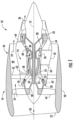
- FIG. 1 illustrates a cross-sectional view of one embodiment of a gas turbine engine 10 that may be utilized within an aircraft in accordance with aspects of the present subject matter, with the gas turbine engine 10 being shown having a longitudinal or axial centerline axis 12 extending therethrough for reference purposes.
- the gas turbine engine 10 may include a core gas turbine engine (indicated generally by reference character 14) and a fan section 16 positioned upstream thereof.
- the core engine 14 may generally include an outer casing 18 that is substantially tubular and defines an annular inlet 20.
- the outer casing 18 may further enclose and support a booster compressor 22 for increasing the pressure of the air that enters the core engine 14 to a first pressure level.
- a high pressure, multi-stage, axial-flow compressor 24 may then receive the pressurized air from the booster compressor 22 and further increase the pressure of such air.
- the pressurized air exiting the high-pressure compressor 24 may then flow to a combustor 26 within which fuel is injected into the flow of pressurized air, with the resulting mixture being combusted within the combustor 26.
- the high energy combustion products are directed from the combustor 26 along the hot gas path of the gas turbine engine 10 to a first (high pressure) turbine 28 for driving the high pressure compressor 24 via a first (high pressure) drive shaft 30, and then to a second (low pressure) turbine 32 for driving the booster compressor 22 and fan section 16 via a second (low pressure) drive shaft 34 that is generally coaxial with first drive shaft 30.
- the combustion products may be expelled from the core engine 14 via an exhaust nozzle 36 to provide propulsive jet thrust.
- each compressor 22, 24 may include a plurality of compressor stages, with each stage including both an annular array of stationary compressor vanes and an annular array of rotating compressor blades positioned immediately downstream of the compressor vanes.
- each turbine 28, 32 may include a plurality of turbine stages, with each stage including both an annular array of stationary nozzle vanes and an annular array of rotating turbine blades positioned immediately downstream of the nozzle vanes.
- the fan section 16 of the gas turbine engine 10 may generally include a rotatable, axial-flow fan rotor assembly 38 that is configured to be surrounded by an annular fan casing 40.
- the fan casing 40 may be configured to be supported relative to the core engine 14 by a plurality of substantially radially-extending, circumferentially-spaced outlet guide vanes 42.
- the fan casing 40 may enclose the fan rotor assembly 38 and its corresponding fan rotor blades 44.
- a downstream section 46 of the fan casing 40 may extend over an outer portion of the core engine 14 so as to define a secondary, or by-pass, airflow conduit 48 that provides additional propulsive jet thrust.
- the second (low pressure) drive shaft 34 may be directly coupled to the fan rotor assembly 38 to provide a direct-drive configuration.
- the second drive shaft 34 may be coupled to the fan rotor assembly 38 via a speed reduction device 37 (e.g., a reduction gear or gearbox) to provide an indirect-drive or geared drive configuration.
- a speed reduction device(s) may also be provided between any other suitable shafts and/or spools within the gas turbine engine 10 as desired or required.
- an initial air flow may enter the gas turbine engine 10 through an associated inlet 52 of the fan casing 40.
- the air flow 50 then passes through the fan rotor blades 44 and splits into a first compressed air flow (indicated by arrow 54) that moves through airflow conduit 48 and a second compressed air flow (indicated by arrow 56) which enters the booster compressor 22.
- the pressure of the second compressed air flow 56 is then increased and enters the high pressure compressor 24 (as indicated by arrow 58).
- the combustion products 60 exit the combustor 26 and flow through the first turbine 28. Thereafter, the combustion products 60 flow through the second turbine 32 and exit the exhaust nozzle 36 to provide thrust for the gas turbine engine 10.
- the gas turbine engine 10 may also include a plurality of access ports defined through its casings and/or frames for providing access to the interior of the core engine 14.
- the gas turbine engine 10 may include a plurality of access ports 62 (only three of which are shown) defined through the outer casing 18 for providing internal access to one or both of the compressors 22, 24.
- the gas turbine engine 10 may include a plurality of access ports 64 (only three of which are shown) defined through the outer casing 18 for providing internal access to one or both of the turbines 28, 32.
- the access ports 62, 64 may be spaced apart axially along the core engine 14.
- the compressor access ports 62 may be spaced apart axially along each compressor 22, 24 such that at least one access port 62 is located at each compressor stage for providing access to the compressor vanes and blades located within such stage.
- the turbine access ports 64 may be spaced apart axially along each turbine 28, 32 such that at least one access port 64 is located at each turbine stage for providing access to the nozzle vanes and turbine blades located within such stage.
- the access ports 62, 64 are generally described herein with reference to providing internal access to one or both of the compressors 22, 24 and/or for providing internal access to one or both of the turbines 28, 32
- the gas turbine engine 10 may include access ports providing access to any suitable internal location of the gas turbine engine 10, such as by including access ports that provide access within the combustor 26 and/or any other suitable component of the gas turbine engine 10.
- the present disclosure may be used to inspect any component of the gas turbine engine 10.
- the exemplary gas turbine engine 10 depicted in FIG. 1 and described above is provided by way of example only.
- the gas turbine engine 10 may have any other suitable configuration, such as a geared connection with the fan rotor blades 44; a variable pitch fan; any suitable number of shafts/spools, compressors, or turbines; etc.
- the gas turbine engine 10 may be configured as an unducted turbofan engine, a turboshaft engine, a turboprop engine, a turbojet engine, etc.
- the first turbine 28 may include a first stage turbine nozzle 66 and an annular array of rotating turbine blades 68 (one of which is shown) located immediately downstream of the first stage turbine nozzle 66.
- the first stage turbine nozzle 66 may generally be defined by an annular flow channel that includes a plurality of radially-extending, circularly-spaced nozzle vanes 70 (one of which is shown).
- the vanes 70 may be supported between a number of arcuate outer bands 72 and arcuate inner bands 74.
- circumferentially spaced turbine blades 68 may generally be configured to extend radially outwardly from a rotor disk (not shown) that rotates about the axial centerline axis 12 ( FIG. 1 ) of the gas turbine engine 10.
- a turbine shroud 76 may be positioned immediately adjacent to the radially outer tips of the turbine blades 68 so as to define the outer radial flowpath boundary for the combustion products 60 flowing through the turbine 28 along the hot gas path of the engine 10.
- the turbine 28 may generally include any number of turbine stages, with each stage including an annular array of nozzle vanes and follow-up turbine blades 68.
- each stage including an annular array of nozzle vanes and follow-up turbine blades 68.
- an annular array of nozzle vanes 78 of a second stage of the turbine 28 may be located immediately downstream of the turbine blades 68 of the first stage of the turbine 28.
- a plurality of access ports 64 may be defined through the turbine casing and/or frame, with each access port 64 being configured to provide access to the interior of the turbine 28 at a different axial location.
- the access ports 64 may, in several embodiments, be spaced apart axially such that each access port 64 is aligned with or otherwise provides interior access to a different stage of the turbine 28.
- a first access port 64A may be defined through the turbine casing/frame to provide access to the first stage of the turbine 28 while a second access port 64B may be defined through the turbine casing/frame to provide access to the second stage of the turbine 28.
- access ports 64 may also be provided for any other stages of the turbine 28 and/or for any turbine stages of the second (or low pressure) turbine 32. It should also be appreciated that, in addition to the axially spaced access ports 64 shown in FIG. 2 , access ports may be provided at differing circumferentially spaced locations. For instance, in one embodiment, a plurality of circumferentially spaced access ports may be defined through the turbine casing/frame at each turbine stage to provide interior access to the turbine 28 at multiple circumferential locations around the turbine stage.
- the compressor 24 may include a plurality of compressor stages, with each stage including both an annular array of fixed compressor vanes 80 (only one of which is shown for each stage) and an annular array of rotatable compressor blades 82 (only one of which is shown for each stage).
- Each row of fixed compressor vanes 80 is generally configured to direct air flowing through the compressor 24 to the row of compressor blades 82 immediately downstream thereof.
- the compressor 24 may include a plurality of access ports 62 defined through the compressor casing/frame, with each access port 62 being configured to provide access to the interior of the compressor 24 at a different axial location.
- the access ports 62 may be spaced apart axially such that each access port 62 is aligned with or otherwise provides interior access to a different stage of the compressor 24.
- first, second, third and fourth access ports 62A, 62B, 62C, 62D are illustrated that provide access to four successive stages, respectively, of the compressor 24.
- access ports may also be provided for any of the other stages of the compressor 24 and/or for any of the stages of the booster compressor 22. It should also be appreciated that, in addition to the axially spaced access ports 62 shown in FIG. 3 , access ports may be also provided at differing circumferentially spaced locations. For instance, in one embodiment, a plurality of circumferentially spaced access ports may be defined through the compressor casing/frame at each compressor stage to provide interior access to the compressor 24 at multiple circumferential locations around the compressor stage.
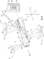
- FIG. 4 a perspective, schematic view of a tool assembly 100 is shown within a gas turbine engine 10 in accordance with an exemplary embodiment of the present subject matter.
- the gas turbine engine 10 depicted schematically in FIG. 4 may be configured in a similar manner as the exemplary gas turbine engine 10 of FIG. 1 .
- the tool assembly 100 includes a body 102, a first camera 104 fixed to the body 102 at a first location X L and in a first spatial position, a second camera 106 fixed to the body 102 at a second location Y L and in a second spatial position, and a controller 108 in operative communication with the first camera 104 and the second camera 106.
- the spatial relationship between the first location X L and the second location Y L is known.
- the body 102 in another exemplary embodiment, is elongated and defines a local longitudinal direction L 1 , a latitudinal direction L 2 , and a transverse direction T.
- the first location X L is spaced from the second location Y L along the longitudinal direction L 1 .
- the spatial position of an object may refer to both the relative position and the relative orientation of the object.
- the first spatial position comprises a first position X P and a first orientation Xo of the first camera 104 relative to the body 102
- the second spatial position comprises a second position Y P and a second orientation Y O of the second camera 106 relative to the body 102.
- the term "orientation" refers to the angular orientation of a camera's field of view or focal line in a three-dimensional space.
- the first orientation Xo defines an angle with the second orientation Yo in a plane defined by the longitudinal direction L 1 and transverse direction T greater than 0, such as greater than 10 degrees, such as greater than 20 degrees, such as greater than 45 degrees, such as less than 360 degrees. More specifically, for the embodiment shown, the angle defined between the first orientation Xo and the second orientation Yo in the plane defined by the longitudinal direction L 1 and transverse direction T is equal to about 90 degrees. Also, for the embodiment shown, the first and second orientations Xo, Yo are each parallel to the plane defined by the latitudinal direction L 2 and transverse direction T.
- the exemplary tool assembly 100 depicted further includes an attachment member 114 to attach the body 102 to another structure.
- the attachment member 114 can be attached to a structure 116 external to the tool assembly 100, e.g., outside of the body of the gas turbine engine 10.
- the attachment member 114 may be attached to or part of a robotic arm, a telescoping arm, a reel, a cable, or any other structure 116 that may maneuver the tool assembly 100 into a desired position relative to the gas turbine engine 10.
- structure 116 may refer to any of the above listed examples.
- the body 102 is a rigid body to which the first camera 104 and the second camera 106 are attached.
- the body 102 may be semi-rigid (e.g., semi-flexible) to allow for easier positioning.
- the body 102 may have one or more sections or segments where the body 102 is flexible, while the other sections or segments remain rigid.
- the sections where the first camera 104 and the second camera 106 are located, as well as the sections in between the cameras may remain rigid.
- each rigid section may be pivoted or otherwise moved relative to the adjacent section as long as the relative positioning is known.
- the body 102 may include a hinge that can be locked into a particular position.
- the first camera 104 may be on an opposite side of the locked hinge of the body 102 from the second camera 106.
- the first location X L and the second location Y L may be on the same side of the hinge.
- the body 102 may be elongated and may further have any of the above described properties.
- the first camera 104 is positioned in view of a reference feature 120.
- the reference feature 120 may be located on a first component 110 of the gas turbine engine 10.
- the second camera 106 is positioned in view of a target feature 125, with the target feature 125 located on a second component 112.
- the terms "reference feature” and "target feature” may be used to refer to locations, portions, or other identifiable regions on one or more components of the gas turbine engine 10 between which the relative positioning and relative orientation is known or may otherwise be calculated or deduced.
- the controller 108 may be able to determine the dimensions of the target feature 125 based on their known spatial relationship.
- the reference feature 120 is a tip of a turbine blade, and the target feature 125 is the tip of a compressor blade.
- the reference feature 120 is a compressor blade, and the target feature 125 is a part of a stator vane.
- the reference feature 120 may refer to part of the turbine shroud 76, while the target feature 125 is a part of a compressor blade or stator vane.
- the reference feature 120 and/or the target feature 125 may refer to part of an airfoil or a guide vane.
- the reference feature 120 and the target feature 125 may be located on any component of the gas turbine engine 10.
- the component may be internal or external to the gas turbine engine 10.
- the body 102 may be partially inserted within the gas turbine engine 10 such that the second camera 106 is in view of an internal component while the first camera 104 remains external to the gas turbine engine 10 and in view of an external component.
- the first camera 104 may be in view of an internal component while the second camera 106 is in view of an external component.
- the target feature 125 may be located on a second component 112 of the gas turbine engine 10, as shown in FIG. 4 .
- the reference feature 120 and the target feature 125 may be located on the same component of the gas turbine engine 10.
- the reference feature 120 and the target feature 125 may both be located on the first component 110 or may both be located on the second component 112. It will be understood that such feature examples are specific to a gas turbine engine 10 and that in utilization in another inspection scenario or example alternative reference and target features would be applicable.
- the first camera 104 and the second camera 106 are shown fixed to the body 102 in the exemplary embodiment, where the body 102 is elongated. In another embodiment, the first camera 104 and the second camera 106 are embedded within the body 102. In other embodiments, the first camera 104 and/or the second camera 106 are mounted on top of the body 102. In yet other embodiments, the first camera 104 may be fixed to the body 102 while the second camera 106 is embedded within the body 102, or vice versa.
- the location of the first camera 104 relative to the second camera 106 (or rather, a difference between the first location X L and the second location Y L ), along with the first spatial position of the first camera 104 within the gas turbine engine provides a reference to determine the second spatial position of the second camera 106 within the gas turbine engine 10.
- the spatial position of an object refers to both the relative position and the relative orientation of the object.
- the first camera 104 may have a first position X P and a first orientation X O within the gas turbine engine 10, collectively, the first spatial position.
- the first position X P and a first orientation X O are relative to the reference feature 120 that is within view of the first camera 104.
- the second camera 106 may have a second position Y P and a second orientation Y O within the gas turbine engine 10, collectively, the second spatial position.
- the second position Y P and the second orientation Y O are relative to the target feature 125 that is within view of the second camera 106.
- the first relative position X P may refer to a distance between the first camera 104 and the reference feature 120 on the first component 110 and the first relative orientation Xo may refer to, e.g., a vector from the reference feature 120 to the first camera 104.
- the second position Y P may refer to a distance between the second camera 106 and the target feature 125 on the second component 112 and the second orientation Y O may refer to, e.g., a vector from the target feature 125 to the second camera 106.
- the distance between the first location X L and the second location Y L along the body 102 is known.
- the relative positions between the first spatial position and the second spatial position are known.
- the second orientation Yo relative to the first orientation Xo is known (e.g., about 90 degrees in the embodiment shown)
- the second position Y P relative to the first position X P is known.
- the controller 108 will receive data indicative of one or more images of a reference feature 120 from the first camera 104 and determine data indicative of the first spatial position of the first camera 104 within the gas turbine engine 10 based at least in part on the received data indicative of the one or more images of the reference feature 120.
- the controller 108 can then determine the second spatial position of the second camera 106 within the gas turbine engine 10 using the known relative locations X L , Y L and the first and second spatial positions of the first and second cameras 104, 106 (e.g., the known first and second spatial positions of the first and second cameras 104, 106 relative to the body 102).
- the controller 108 can be configured to receive data indicative of one or more images of a target feature 125 using the second camera 106 and to determine data indicative of dimensions of the target feature 125 based at least in part on the received data indicative of the one or more images of the target feature 125.
- the controller 108 may use the determined data indicative of the dimensions of the target feature 125 to generate a three-dimensional representation of the target feature 125.
- This three-dimensional representation of the target feature 125 may include measurements relating to the depth, size, and/or location of the target feature 125.
- the target feature 125 is a defect on a component, e.g., the second component 112, and the three-dimensional representation can be used to inspect the defect and determine maintenance and/or remediation methods that are needed, if any.
- the tool assembly 100 further includes additional cameras, such as a third camera 107 fixed to the body 102 at a third location Z L spaced from the first location X L and the second location Y L , where the distance between Z L , Y L , and/or X L is known.
- the third camera 107 is positioned in view of an auxiliary feature 127.
- the auxiliary feature 127 may be located on the same component as the reference feature 120, the target feature 125, or both.
- the auxiliary feature 127 may be located on a third component 113 of the gas turbine engine 10 that is different from both the first component 110 and the second component 112.
- the third camera 107 has a third spatial position, where the third spatial position is known relative to the first spatial position, the second spatial position, or both.
- the third camera 107 may have a third position Z P and a third orientation Z O , within the gas turbine engine 10, collectively, the third spatial position.
- the third position Z P and a third orientation Z O are relative to the auxiliary feature 127 that is within view of the third camera 107.
- the controller 108 may be further configured to determine the third spatial position based at least in part on the first spatial position of the first camera 104 and/or the second spatial position of the second camera 106, obtain one or more images of the auxiliary feature 127 using the third camera 107, derive one or more dimensions of the auxiliary feature 127, and generate a three-dimensional representation of the auxiliary feature 127 based at least in part on the determined data indicative of the one or more dimensions of the auxiliary feature 127.
- the cameras can represent any suitable imaging device including any optical sensor capable of capturing still or moving images. Suitable types of cameras may be a CMOS camera, a CCD camera, an analog, a digital camera, a video camera or any other type of device capable of capturing an image. It is further contemplated that a borescope camera or an endoscope camera can be utilized. Further still, the camera may be a monocular camera or a binocular camera. For example, in some embodiments, the first camera 104 and the second camera 106 may record images at a rate of at least about 2 frames-per-second (FPS) and may have a resolution of greater than 0.1 megapixels (MP), such as greater than 1 MP, 2 MP, or 3 MP, and up to about 750 MP.
- FPS frames-per-second
- the first camera 104 and the second camera 106 may each include a time mechanism to enable the camera to record images periodically after a specified time interval. Additionally, or alternatively, where either the first camera 104 or the second camera 106 are positioned in view of blades, the tool assembly 100 may include a trigger mechanism that is activated by rotation of the blades. In some embodiments, the first camera 104, the second camera 106, or both may include a video recording device, such that the first camera 104 is capable of recording video of the first component 110 and/or the second camera 106 is capable of recording video of the second component 112.
- the first camera 104 and second camera 106 may be calibrated before images are taken.
- calibration of the first and second cameras 104 and 106 may include estimating intrinsic and/or extrinsic parameters to ensure accuracy.
- the first and second cameras 104 and 106 may be calibrated to account for angular separation and/or circumferential distance between pixels.
- Camera calibration may also account for lens distortions and lens mounting errors (e.g., after the first camera 104 and the second camera 106 are fixed to the body 102). Further, calibrating the cameras may also help measure dimensions or determine the location of the camera within the gas turbine engine 10. It will be appreciated that the first and second cameras 104 and 106 may additionally or alternatively be calibrated in any other way.
- the first camera 104, the second camera 106, or both may include any other image sensing devices, such as infrared, ultrasound, inductive, position encoder, and/or eddy-current sensing devices.
- the first camera 104 and the second camera 106 may each include one or more sensors 90A, 90B, such as positioning sensors.
- the term "positioning sensors” may refer to any sensors that are capable of providing feedback to the controller 108 to help position the body 102.
- the sensors 90A, 90B may be proximity sensors, optical sensors, and/or tactile sensors.
- the one or more sensors 90A, 90B provides data to the controller 108.
- the sensors may help position the body 102 within the gas turbine engine 10.
- the one or more sensors 90A, 90B may locate entryways or passages for the tool assembly 100.
- feedback from the one or more sensors 90A and 90B may be used to provide a dimensional data point relating to the reference feature, the target feature, or both.
- the one or more sensors 90A and 90B may comprise Inertial Measurement Units ("IMUs"). These IMUs may further comprise accelerometers, gyroscopes, magnetometers, and/or any other tools that are capable of obtaining the 3D position and/or orientation of an object.
- the sensors 90A and 90B may provide a dimensional (e.g., angular) data point for the images taken by either the first camera 104, the second camera 106, or both.
- the dimensional data point(s) for the images taken by the first camera 104 may provide a scale for the reference feature 120.
- Such a configuration may more specifically provide for a scale of the reference features 120 to be determined independently of any prior data of the reference feature 120 (such as independently of any CAD information or the like).
- the first camera 104, the second camera 106, a light source, and a storage device may form an integrated assembly.
- the light source may be light emitting diodes (LEDs), fluorescent lights, incandescent lights, or any other suitable light device, and may be oriented to illuminate the compressor blades 82 or any other region capable of image record by the first and second cameras 104, 106. Multiple color light sources may be used, such as blue, green, red, white, or other colors.
- the storage device may be a non-volatile memory device (e.g., a flash memory device) configured to provide a desired storage capacity. In one embodiment, the storage device may provide at least 2 GB, 4 GB, 6 GB, or 8 GB of memory, and up to about 2TB of memory.
- the exemplary controller 108 depicted in FIG. 4 is configured to receive the data sensed from the one or more sensors 90A, 90B and, e.g., may make control decisions for the tool assembly 100 based on the received data.
- the controller 108 depicted in FIG. 4 may be a stand-alone controller 108 for the tool assembly 100, or alternatively, may be integrated into one or more other controllers.
- the controller 108 can include one or more computing device(s) 130.
- the computing device(s) 130 can include one or more processor(s) 131 and one or more memory device(s) 132.
- the one or more processor(s) 131 can include any suitable processing device, such as a microprocessor, microcontroller, integrated circuit, logic device, and/or other suitable processing device.
- the one or more memory device(s) 132 can include one or more computer-readable media, including, but not limited to, non-transitory computer-readable media, RAM, ROM, hard drives, flash drives, and/or other memory devices.
- the one or more memory device(s) 132 can store information accessible by the one or more processor(s) 131, including computer-readable instructions 133 that can be executed by the one or more processor(s) 131.
- the computer-readable instructions 133 can be any set of instructions that when executed by the one or more processor(s) 131, cause the one or more processor(s) 131 to perform operations.
- the computer-readable instructions 133 can be executed by the one or more processor(s) 131 to cause the one or more processor(s) 131 to perform operations, such as any of the operations and functions for which the controller 108 and/or the computing device(s) are configured, the operations for operating a tool assembly 100 (e.g., method 200), as described herein, and/or any other operations or functions of the one or more computing device(s) 130.
- the computer-readable instructions 133 can be software written in any suitable programming language or can be implemented in hardware. Additionally, and/or alternatively, the computer-readable instructions 133 can be executed in logically and/or virtually separate threads on processor(s) 131.
- the memory device(s) 132 can further store data 134 that can be accessed by the processor(s) 131.
- the data 134 can include data indicative of power flows, data indicative of engine/ aircraft operating conditions, and/or any other data and/or information described herein.
- the computing device(s) 130 can also include a network interface 135 used to communicate, for example, with the other components of the tool assembly 100, the gas turbine engine 10 incorporating tool assembly 100, the aircraft incorporating the gas turbine engine, etc.
- the gas turbine engine 10 and/or tool assembly 100 further includes one or more sensors 90A, 90B for sensing data indicative of one or more parameters of the gas turbine engine 10, the tool assembly 100, or both.
- the controller 108 of the tool assembly 100 is operably coupled to the one or more sensors 90A, 90B through, e.g., the network interface 135, such that the controller 108 may receive data indicative of various operating parameters sensed by the one or more sensors 90A, 90B during operation. Further, for the embodiment shown in FIG.
- the controller 108 is operably coupled to, e.g., the sensors 90A and 90B on or adjacent to the first camera 104 and the second camera 106, respectively. In such a manner, the controller 108 may be configured to position the body 102 in response to, for example, the data 134 sensed by the one or more sensors 90A, 90B.
- the first camera 104 and the second camera 106 may each include one or more sensors 90A, 90B as part of the first and second cameras 104, 106.
- the network interface 135 can include any suitable components for interfacing with one or more network(s), including for example, transmitters, receivers, ports, controllers, antennas, and/or other suitable components.
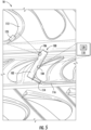
- FIG. 5 a cross sectional view of the compressor blades 82 and the tool assembly 100 in position for imaging the gas turbine engine 10 as described above with reference to FIGS. 1 through 4 is illustrated in accordance with aspects of the present subject matter.
- the tool assembly 100 and, more specifically, the body 102 is inserted through borescope holes or other access ports 62, 64.
- the tool assembly 100 is thereby able to access the first and second components 110, 112 of the gas turbine engine 10 without substantially disassembling the gas turbine engine 10.
- the first component 110 is the turbine shroud 76, as shown in FIG. 5 .
- the first component 110 may be internal or external to the gas turbine engine 10.
- the second component 112 may be internal or external to the gas turbine engine 10.
- the position of the tool assembly 100 allows the first camera 104 and the second camera 106 to view the reference feature 120 and the target feature 125, respectively.
- the attachment member 114 and structure 116 are used to maneuver the body 102 until it is in position within the gas turbine engine 10.
- the body 102 is in position when each of the first camera 104 and the second camera 106 have at least the reference feature 120 and the target feature 125, respectively, within its field of view.
- the reference feature 120 is located on the first component 110
- the target feature 125 is located on the second component 112.
- the second component 112 is the component that is within the field of view of the second camera 106 as shown.
- the term "field of view" of a camera is defined as the maximum area of a sample that a camera can image and is typically dependent, at least in part, on the focal length of the lens of the camera.
- the field of view may also be defined in any other manner as known to those of ordinary skill in the art.
- FIG. 6 illustrates a flow diagram of one embodiment of a method for inspecting components of the gas turbine engine 10 described above with reference to FIG. 1 .
- the method 200 images, measures, and models the target feature 125.
- method 200 generally includes, at 210, positioning the body 102 such that the first camera 104 is in view of the reference feature 120; at 220, receiving data indicative of one or more images of the reference feature 120 from the first camera 104; at 230, determining a first spatial position of the first camera 104 based at least in part on the received data indicative of the one or more images of the reference feature 120; and, at 240, determining a second spatial position of the second camera 106 based on the first spatial position. Additionally, in other embodiments, the method may further include receiving data indicative of one or more images of a target feature 125 using the second camera 106. Furthermore, in the exemplary embodiment, the controller 108 is also configured to generate a three-dimensional representation of the target feature 125 and/or to derive dimensions of the target feature 125. Each of these blocks will be described below in more detail.
- the body 102 is positioned such that the first camera 104 is in view of a reference feature 120.
- the body 102 is positioned such that the first camera 104 is within view of the reference feature 120 of the first component 110 and such that the second camera 106 is in view of the target feature 125 of the second component 112 of the gas turbine engine 10.
- the reference feature 120 and the target feature 125 may be located on the same component.
- the reference feature 120 may refer to the entirety of the first component 110.
- the reference feature 120 refers to a compressor blade.
- the reference feature 120 may refer to any other component of a gas turbine engine 10.
- the reference feature 120 is a portion of the first component 110, such as a specific feature of the first component 110.
- the reference feature 120 may be only a tip of a compressor blade.
- Positioning the body 102 may additionally include inserting the body 102 into the gas turbine engine 10. The body 102 may be inserted into the gas turbine engine 10 through borescope holes or other access ports 62, 64. Further, the attachment member 114 and structure 116 may help position the body 102 such that the first camera 104 is within view of the reference feature 120 and such that the second camera 106 is in view of the target feature 125.
- the controller 108 receives data indicative of one or more images of the reference feature 120 from the first camera 104.
- the first camera 104 will take one or more images of the reference feature 120 that is within its field of view.
- the data indicative of the one or more images can be saved in the storage device temporarily, e.g., in RAM, or permanently, e.g., transferred to a more permanent storage device.
- the information regarding the reference feature 120 is already known.
- This information may be three-dimensional information of the reference feature 120.
- the term "three-dimensional information" refers to size, location, and/or depth of the reference feature 120.
- the location of the reference feature 120 may refer to a spatial position within a three-dimensional space, e.g., the L 1 L 2 T plane.
- the controller 108 may obtain the information by estimating, determining, or measuring actual measurements of the reference feature 120 or in any other manner that would reasonably be able to obtain this information.
- obtaining the three-dimensional information regarding the reference feature 120 includes obtaining information from a computer aided design (CAD) model.
- CAD computer aided design
- the CAD model may be inputted by a user or gathered from a database.
- the CAD model may also be derived through parallax using monocular cameras.
- the reference feature 120 may be located on the first component 110, which may, for example, be a rotor blade.
- the model number for the first component 110 (rotor blade, in this example) may provide sufficient information.
- a user can then input the model number into the controller 108 to search a database of CAD models, blueprints, schematics, or any other type of reference information that is capable of providing three-dimensional information.
- the three-dimensional information may be obtained from the one or more sensors 90A and 90B.
- the one or more sensors 90A and 90B may further comprise IMUs, as mentioned above.
- the IMUs may provide this three-dimensional information to the controller 108.
- the controller 108 determines the first spatial position of the first camera 104 based at least in part on the one or more images of the reference feature 120.
- the first spatial position may be derived using an algorithm executed by the controller 108 and can be stored in the storage memory device.
- the spatial position of an object may be stored in coordinates form, in vector form, or in any other form that may describe the object's spatial position.
- the controller 108 will be able to determine the first spatial position of the first camera 104 relative to the reference feature 120 based at least in part on the images of the reference feature 120 and the known information of the reference feature 120. For example, by comparing the images of the reference feature 120 taken using the first camera 104 with the known three-dimensional information about the reference feature 120, the controller 108 will be able to determine the first spatial position of the first camera 104 relative to the reference feature 120.
- the controller 108 determines the second spatial position of the second camera 106.
- the controller 108 executes an algorithm to use the now known first spatial position of the first camera 104 to calculate the second spatial position of the second camera 106.
- the controller 108 will be able to determine the second spatial position based on this known relative spatial position and the first spatial position determined at 230.
- Method 200 may further include obtaining one or more images of the target feature 125 using the second camera 106.
- the target feature 125 is a feature on the second component 112.
- the target feature 125 may be a defect or any particular part of the second component 112.
- the one or more images of the target feature 125 and/or the second spatial position of the second camera 106 may be used to derive data indicative of one or more dimensions of the target feature 125.
- the dimensions of the target feature 125 may be stored on the storage memory device.
- the received data indicative of one or more dimensions of the target feature 125 is used to create a three-dimensional representation of the target feature 125.
- the three-dimensional representation may be a point cloud.
- a point cloud is set of data points defined in a coordinate system and may include color and depth data.
- the point cloud may be used to create a CAD model.
- the CAD model may use any CAD software, and may be generated from any of a large variety of well-known computer aided design (CAD) software systems such as AutoCAD ® , TurboCAD ® , DesignCAD 3D Max, etc.
- CAD computer aided design
- the CAD model may be a topographical model, a surface model, a wireframe model, a shell model, or any other type of CAD model. It will be appreciated that the present disclosure includes any other representation that may accurately portray the target feature 125.
- each of the first camera 104 and the second camera 106 may obtain two or more sets of images, where each set of images includes one or more images.
- the first set of images may be taken when the first camera 104 and the second camera 106 are in a first position.
- the second set of images may be taken when the first and second cameras 104 and 106 are at a second position spaced apart from the first position by a circumferential distance, e.g., an engine rotation angle.
- each set of images may be taken synchronously (e.g., at or substantially around the same time) by the first and second cameras 104 and 106.
- the circumferential distance is calculated using at least one reference feature 120 in the first and second sets of images from the first camera 104.
- the tool assembly 100 also includes sensors 90A and 90B, and where the sensors 90A and 90B further include IMUs, the circumferential distance may be obtained from the IMUs. The first and second sets of images taken by the second camera 106 may then be used to determine the dimensions of the target feature 125 based on the circumferential distance.
- the tool assembly 100 may be used in any compatible machine across different industries.
- the tool assembly 100 may further include a third camera 107 fixed at a third location and at a third spatial position along the body 102, where the third camera 107 is positioned in view of an auxiliary feature 127 and/or third component 113.
- the method 200 will further include the steps of determining the third spatial position based at least in part on the first spatial position and/or the second spatial position; receiving data indicative one or more images of the auxiliary feature 127 using the third camera 107, determining data indicative of one or more dimensions of the auxiliary feature 127, and generating a three-dimensional representation of the auxiliary feature 127 based at least on the determined data indicative of one or more dimensions of the auxiliary feature 127.
- the tool assembly 100 may also include four, five, six, seven, or more cameras operating in the same manner as described.
- the additional cameras may be operated simultaneously with the first camera 104 and the second camera 106 to allow for simultaneous imaging of multiple features and/or components.
- the tool assembly 100 is described herein with reference to machines and gas turbine engines specifically, the tool assembly 100 is also applicable to other fields, e.g., the medical field to inspect difficult to reach places and/or to estimate sizes of tumors and other foreign objects within a human body.
Landscapes
- Engineering & Computer Science (AREA)
- Physics & Mathematics (AREA)
- General Physics & Mathematics (AREA)
- General Engineering & Computer Science (AREA)
- Mechanical Engineering (AREA)
- Computer Vision & Pattern Recognition (AREA)
- Chemical & Material Sciences (AREA)
- Theoretical Computer Science (AREA)
- Analytical Chemistry (AREA)
- Biochemistry (AREA)
- General Health & Medical Sciences (AREA)
- Immunology (AREA)
- Pathology (AREA)
- Life Sciences & Earth Sciences (AREA)
- Health & Medical Sciences (AREA)
- Quality & Reliability (AREA)
- Combustion & Propulsion (AREA)
- Geometry (AREA)
- Signal Processing (AREA)
- Structures Of Non-Positive Displacement Pumps (AREA)
- Length Measuring Devices By Optical Means (AREA)
Applications Claiming Priority (2)
| Application Number | Priority Date | Filing Date | Title |
|---|---|---|---|
| IN202111033483 | 2021-07-26 | ||
| EP21196698.1A EP4124822B1 (fr) | 2021-07-26 | 2021-09-14 | Système et procédé d'utilisation d'un ensemble outil |
Related Parent Applications (2)
| Application Number | Title | Priority Date | Filing Date |
|---|---|---|---|
| EP21196698.1A Division EP4124822B1 (fr) | 2021-07-26 | 2021-09-14 | Système et procédé d'utilisation d'un ensemble outil |
| EP21196698.1A Division-Into EP4124822B1 (fr) | 2021-07-26 | 2021-09-14 | Système et procédé d'utilisation d'un ensemble outil |
Publications (2)
| Publication Number | Publication Date |
|---|---|
| EP4474797A2 true EP4474797A2 (fr) | 2024-12-11 |
| EP4474797A3 EP4474797A3 (fr) | 2025-03-12 |
Family
ID=77821558
Family Applications (2)
| Application Number | Title | Priority Date | Filing Date |
|---|---|---|---|
| EP21196698.1A Active EP4124822B1 (fr) | 2021-07-26 | 2021-09-14 | Système et procédé d'utilisation d'un ensemble outil |
| EP24209257.5A Pending EP4474797A3 (fr) | 2021-07-26 | 2021-09-14 | Système et procédé d'utilisation d'un ensemble outil |
Family Applications Before (1)
| Application Number | Title | Priority Date | Filing Date |
|---|---|---|---|
| EP21196698.1A Active EP4124822B1 (fr) | 2021-07-26 | 2021-09-14 | Système et procédé d'utilisation d'un ensemble outil |
Country Status (3)
| Country | Link |
|---|---|
| US (2) | US11913345B2 (fr) |
| EP (2) | EP4124822B1 (fr) |
| CN (2) | CN120867849B (fr) |
Families Citing this family (4)
| Publication number | Priority date | Publication date | Assignee | Title |
|---|---|---|---|---|
| US11913345B2 (en) | 2021-07-26 | 2024-02-27 | General Electric Company | System and method of using a tool assembly |
| GB2605703B (en) * | 2022-04-04 | 2024-05-08 | Rolls Royce Plc | Methods and systems of monitoring a condition of a component of a gas turbine engine |
| US12523617B2 (en) * | 2024-02-29 | 2026-01-13 | Rtx Corporation | Autonomous inspection of a surface topology of an airfoil of a gas turbine engine |
| US12529551B2 (en) | 2024-02-29 | 2026-01-20 | Rtx Corporation | Autonomous inspection of a surface topology of an airfoil of a gas turbine engine |
Family Cites Families (38)
| Publication number | Priority date | Publication date | Assignee | Title |
|---|---|---|---|---|
| DE69532126T2 (de) | 1994-05-19 | 2004-07-22 | Geospan Corp., Plymouth | Verfahren zum sammeln und verarbeiten visueller und räumlicher positionsinformation |
| EP1085769B1 (fr) | 1999-09-15 | 2012-02-01 | Sharp Kabushiki Kaisha | Dispositif de prise d'images stéréoscopiques |
| US20030179920A1 (en) | 2002-03-13 | 2003-09-25 | Intelligent Machine Concepts, L.L.C. | Inspection system for determining object orientation and defects |
| US6969821B2 (en) | 2003-06-30 | 2005-11-29 | General Electric Company | Airfoil qualification system and method |
| US7272254B2 (en) | 2003-07-09 | 2007-09-18 | General Electric Company | System and method for analyzing and identifying flaws in a manufactured part |
| US8477154B2 (en) | 2006-03-20 | 2013-07-02 | Siemens Energy, Inc. | Method and system for interactive virtual inspection of modeled objects |
| US7627447B2 (en) | 2007-01-23 | 2009-12-01 | The Boeing Company | Method and apparatus for localizing and mapping the position of a set of points on a digital model |
| US8060835B2 (en) | 2007-06-05 | 2011-11-15 | The Boeing Company | Three dimensional defect mapping |
| EP2254728B1 (fr) | 2008-02-19 | 2019-09-11 | Rolls-Royce Corporation | Système et procédé pour réparer des objets |
| WO2010015086A1 (fr) | 2008-08-06 | 2010-02-11 | Creaform Inc. | Système pour balayage tridimensionnel adaptatif de caractéristiques de surface |
| US8602722B2 (en) | 2010-02-26 | 2013-12-10 | General Electric Company | System and method for inspection of stator vanes |
| DK2568870T3 (en) | 2010-03-30 | 2018-08-13 | 3Shape As | SCREENING SPACES WITH LIMITED AVAILABILITY |
| US20140300729A1 (en) * | 2010-05-03 | 2014-10-09 | United Technologies Corporation | Probe for Inspection System |
| EP2752808A4 (fr) | 2011-08-30 | 2015-02-18 | Fujitsu Ltd | Dispositif d'imagerie, programme de support de travail, procédé de fourniture d'informations et programme de fourniture d'informations |
| GB2496903B (en) | 2011-11-28 | 2015-04-15 | Rolls Royce Plc | An apparatus and a method of inspecting a turbomachine |
| KR101702331B1 (ko) * | 2012-08-23 | 2017-02-22 | 지멘스 에너지, 인코포레이티드 | 터닝 기어 모드 중인 오프라인 산업 가스 터빈들 및 다른 발전 기계류의 광학 검사하는 시스템 및 방법 |
| US9228941B2 (en) * | 2012-11-07 | 2016-01-05 | Solar Turbines Incorporated | Combustor imaging inspection system |
| US9348001B2 (en) * | 2013-10-21 | 2016-05-24 | General Electric Company | Method and system for detecting surface features on turbine components |
| US9567907B2 (en) * | 2015-02-24 | 2017-02-14 | General Electrical Company | Imaging assisted gas turbine anti-icing system |
| JP6434834B2 (ja) | 2015-03-19 | 2018-12-05 | 株式会社日立ソリューションズ | 検査対象物抽出装置、及び検査対象物抽出方法 |
| JP6917378B2 (ja) | 2015-09-17 | 2021-08-11 | ファゾム・オプティクス・インコーポレイテッド | マルチビューディスプレイ並びに関連するシステム及び方法 |
| US10197473B2 (en) * | 2015-12-09 | 2019-02-05 | General Electric Company | System and method for performing a visual inspection of a gas turbine engine |
| US10920590B2 (en) | 2016-06-30 | 2021-02-16 | General Electric Company | Turbine assembly maintenance methods |
| US10252812B2 (en) * | 2016-09-28 | 2019-04-09 | General Electric Company | System and method for controlling fuel flow to a gas turbine engine based on motion sensor data |
| US10717166B2 (en) | 2016-12-02 | 2020-07-21 | General Electric Company | Motorized apparatus for use with rotary machines |
| WO2018136262A1 (fr) | 2017-01-20 | 2018-07-26 | Aquifi, Inc. | Systèmes et procédés de détection de défaut |
| BR102017002219B1 (pt) | 2017-02-02 | 2020-01-07 | Vale S/A | Sistema e método para o monitoramento de rodas ferroviárias |
| US10808534B2 (en) | 2017-02-08 | 2020-10-20 | General Electric Company | Reconfigurable maintenance apparatus |
| US10775315B2 (en) | 2018-03-07 | 2020-09-15 | General Electric Company | Probe insertion system |
| US10819972B2 (en) | 2018-05-03 | 2020-10-27 | Osram Sylvania Inc. | Method and apparatus for light and computer vision based dimensional metrology and 3D reconstruction |
| US10958843B2 (en) * | 2018-05-04 | 2021-03-23 | Raytheon Technologies Corporation | Multi-camera system for simultaneous registration and zoomed imagery |
| US11608756B2 (en) | 2018-07-17 | 2023-03-21 | General Electric Company | Service apparatus for use with rotary machines |
| CN109272453B (zh) | 2018-08-31 | 2023-02-10 | 上海盎维信息技术有限公司 | 基于3d摄像机的建模装置及定位方法 |
| US11103964B2 (en) | 2018-12-06 | 2021-08-31 | General Electric Company | Service apparatus for use with rotary machines |
| DE102019100820A1 (de) * | 2019-01-14 | 2020-07-16 | Lufthansa Technik Aktiengesellschaft | Verfahren und Vorrichtung zur Inspektion schwer erreichbarer Komponenten |
| DE102019100821A1 (de) * | 2019-01-14 | 2020-07-16 | Lufthansa Technik Aktiengesellschaft | Boroskop zur optischen Inspektion von Gasturbinen |
| GB201914638D0 (en) * | 2019-10-10 | 2019-11-27 | Rolls Royce Plc | Inspection system |
| US11913345B2 (en) | 2021-07-26 | 2024-02-27 | General Electric Company | System and method of using a tool assembly |
-
2021
- 2021-09-10 US US17/471,923 patent/US11913345B2/en active Active
- 2021-09-14 EP EP21196698.1A patent/EP4124822B1/fr active Active
- 2021-09-14 EP EP24209257.5A patent/EP4474797A3/fr active Pending
- 2021-10-18 CN CN202510993963.4A patent/CN120867849B/zh active Active
- 2021-10-18 CN CN202111211388.6A patent/CN115680899B/zh active Active
-
2024
- 2024-01-23 US US18/420,402 patent/US12345167B2/en active Active
Also Published As
| Publication number | Publication date |
|---|---|
| CN120867849A (zh) | 2025-10-31 |
| US20230024295A1 (en) | 2023-01-26 |
| EP4124822A1 (fr) | 2023-02-01 |
| US12345167B2 (en) | 2025-07-01 |
| CN120867849B (zh) | 2026-02-24 |
| EP4474797A3 (fr) | 2025-03-12 |
| US11913345B2 (en) | 2024-02-27 |
| CN115680899A (zh) | 2023-02-03 |
| CN115680899B (zh) | 2025-08-12 |
| US20240159162A1 (en) | 2024-05-16 |
| EP4124822B1 (fr) | 2024-12-11 |
Similar Documents
| Publication | Publication Date | Title |
|---|---|---|
| US12345167B2 (en) | System and method of using a tool assembly | |
| US11536670B2 (en) | System and method for engine inspection | |
| EP3179238B1 (fr) | Système et procédé permettant d'effectuer une inspection visuelle d'un moteur à turbine à gaz | |
| US10196927B2 (en) | System and method for locating a probe within a gas turbine engine | |
| US10217208B2 (en) | Apparatus and a method of inspecting a turbomachine | |
| EP3623788B1 (fr) | Système de classement de détresse automatisé | |
| EP3667021B1 (fr) | Détermination d'un poids de moment d'un composant sur la base de la géométrie de surface mesurée/du modèle solide du composant | |
| US10196922B2 (en) | System and method for locating a probe within a gas turbine engine | |
| US20240273706A1 (en) | Inspecting parts using geometric models | |
| GB2493770A (en) | Determining the position and orientation of a remote end of a boroscope | |
| CN119470461B (zh) | 用于发动机组件检查的3d成像 | |
| US20250252551A1 (en) | Inspection systems and associated methods for gas turbine engine components |
Legal Events
| Date | Code | Title | Description |
|---|---|---|---|
| PUAI | Public reference made under article 153(3) epc to a published international application that has entered the european phase |
Free format text: ORIGINAL CODE: 0009012 |
|
| STAA | Information on the status of an ep patent application or granted ep patent |
Free format text: STATUS: THE APPLICATION HAS BEEN PUBLISHED |
|
| AC | Divisional application: reference to earlier application |
Ref document number: 4124822 Country of ref document: EP Kind code of ref document: P |
|
| AK | Designated contracting states |
Kind code of ref document: A2 Designated state(s): AL AT BE BG CH CY CZ DE DK EE ES FI FR GB GR HR HU IE IS IT LI LT LU LV MC MK MT NL NO PL PT RO RS SE SI SK SM TR |
|
| REG | Reference to a national code |
Ref country code: DE Ref legal event code: R079 Free format text: PREVIOUS MAIN CLASS: G01N0021954000 Ipc: G01B0011240000 |
|
| PUAL | Search report despatched |
Free format text: ORIGINAL CODE: 0009013 |
|
| AK | Designated contracting states |
Kind code of ref document: A3 Designated state(s): AL AT BE BG CH CY CZ DE DK EE ES FI FR GB GR HR HU IE IS IT LI LT LU LV MC MK MT NL NO PL PT RO RS SE SI SK SM TR |
|
| RIC1 | Information provided on ipc code assigned before grant |
Ipc: G01N 21/954 20060101ALI20250131BHEP Ipc: F01D 21/00 20060101ALI20250131BHEP Ipc: G01B 21/04 20060101ALI20250131BHEP Ipc: G01B 11/245 20060101ALI20250131BHEP Ipc: G01B 11/24 20060101AFI20250131BHEP |
|
| STAA | Information on the status of an ep patent application or granted ep patent |
Free format text: STATUS: REQUEST FOR EXAMINATION WAS MADE |
|
| 17P | Request for examination filed |
Effective date: 20250902 |
|
| GRAP | Despatch of communication of intention to grant a patent |
Free format text: ORIGINAL CODE: EPIDOSNIGR1 |
|
| RIC1 | Information provided on ipc code assigned before grant |
Ipc: G01B 11/24 20060101AFI20260212BHEP Ipc: G01B 11/245 20060101ALI20260212BHEP Ipc: G01B 21/04 20060101ALI20260212BHEP Ipc: F01D 21/00 20060101ALI20260212BHEP Ipc: G01N 21/954 20060101ALI20260212BHEP |
|
| STAA | Information on the status of an ep patent application or granted ep patent |
Free format text: STATUS: GRANT OF PATENT IS INTENDED |
|
| INTG | Intention to grant announced |
Effective date: 20260318 |