EP4474728A2 - Geothermische anlage zur gewinnung von energie aus einem unterhalb des meeresbodens befindlichen geothermischen reservoir - Google Patents
Geothermische anlage zur gewinnung von energie aus einem unterhalb des meeresbodens befindlichen geothermischen reservoir Download PDFInfo
- Publication number
- EP4474728A2 EP4474728A2 EP24208190.9A EP24208190A EP4474728A2 EP 4474728 A2 EP4474728 A2 EP 4474728A2 EP 24208190 A EP24208190 A EP 24208190A EP 4474728 A2 EP4474728 A2 EP 4474728A2
- Authority
- EP
- European Patent Office
- Prior art keywords
- geothermal
- riser
- reservoir
- ocean
- geothermal reservoir
- Prior art date
- Legal status (The legal status is an assumption and is not a legal conclusion. Google has not performed a legal analysis and makes no representation as to the accuracy of the status listed.)
- Granted
Links
Images













Classifications
-
- F—MECHANICAL ENGINEERING; LIGHTING; HEATING; WEAPONS; BLASTING
- F24—HEATING; RANGES; VENTILATING
- F24T—GEOTHERMAL COLLECTORS; GEOTHERMAL SYSTEMS
- F24T10/00—Geothermal collectors
- F24T10/20—Geothermal collectors using underground water as working fluid; using working fluid injected directly into the ground, e.g. using injection wells and recovery wells
-
- B—PERFORMING OPERATIONS; TRANSPORTING
- B01—PHYSICAL OR CHEMICAL PROCESSES OR APPARATUS IN GENERAL
- B01D—SEPARATION
- B01D19/00—Degasification of liquids
- B01D19/0068—General arrangements, e.g. flowsheets
-
- C—CHEMISTRY; METALLURGY
- C25—ELECTROLYTIC OR ELECTROPHORETIC PROCESSES; APPARATUS THEREFOR
- C25B—ELECTROLYTIC OR ELECTROPHORETIC PROCESSES FOR THE PRODUCTION OF COMPOUNDS OR NON-METALS; APPARATUS THEREFOR
- C25B1/00—Electrolytic production of inorganic compounds or non-metals
- C25B1/01—Products
- C25B1/02—Hydrogen or oxygen
- C25B1/04—Hydrogen or oxygen by electrolysis of water
- C25B1/042—Hydrogen or oxygen by electrolysis of water by electrolysis of steam
-
- E—FIXED CONSTRUCTIONS
- E21—EARTH OR ROCK DRILLING; MINING
- E21B—EARTH OR ROCK DRILLING; OBTAINING OIL, GAS, WATER, SOLUBLE OR MELTABLE MATERIALS OR A SLURRY OF MINERALS FROM WELLS
- E21B41/00—Equipment or details not covered by groups E21B15/00 - E21B40/00
- E21B41/005—Waste disposal systems
-
- F—MECHANICAL ENGINEERING; LIGHTING; HEATING; WEAPONS; BLASTING
- F03—MACHINES OR ENGINES FOR LIQUIDS; WIND, SPRING, OR WEIGHT MOTORS; PRODUCING MECHANICAL POWER OR A REACTIVE PROPULSIVE THRUST, NOT OTHERWISE PROVIDED FOR
- F03G—SPRING, WEIGHT, INERTIA OR LIKE MOTORS; MECHANICAL-POWER PRODUCING DEVICES OR MECHANISMS, NOT OTHERWISE PROVIDED FOR OR USING ENERGY SOURCES NOT OTHERWISE PROVIDED FOR
- F03G4/00—Devices for producing mechanical power from geothermal energy
- F03G4/023—Devices for producing mechanical power from geothermal energy characterised by the geothermal collectors
- F03G4/026—Devices for producing mechanical power from geothermal energy characterised by the geothermal collectors open loop geothermal collectors
-
- F—MECHANICAL ENGINEERING; LIGHTING; HEATING; WEAPONS; BLASTING
- F24—HEATING; RANGES; VENTILATING
- F24T—GEOTHERMAL COLLECTORS; GEOTHERMAL SYSTEMS
- F24T10/00—Geothermal collectors
- F24T10/30—Geothermal collectors using underground reservoirs for accumulating working fluids or intermediate fluids
-
- F—MECHANICAL ENGINEERING; LIGHTING; HEATING; WEAPONS; BLASTING
- F24—HEATING; RANGES; VENTILATING
- F24T—GEOTHERMAL COLLECTORS; GEOTHERMAL SYSTEMS
- F24T10/00—Geothermal collectors
- F24T10/40—Geothermal collectors operated without external energy sources, e.g. using thermosiphonic circulation or heat pipes
-
- F—MECHANICAL ENGINEERING; LIGHTING; HEATING; WEAPONS; BLASTING
- F24—HEATING; RANGES; VENTILATING
- F24T—GEOTHERMAL COLLECTORS; GEOTHERMAL SYSTEMS
- F24T50/00—Geothermal systems
-
- F—MECHANICAL ENGINEERING; LIGHTING; HEATING; WEAPONS; BLASTING
- F24—HEATING; RANGES; VENTILATING
- F24T—GEOTHERMAL COLLECTORS; GEOTHERMAL SYSTEMS
- F24T2201/00—Prediction; Simulation
-
- Y—GENERAL TAGGING OF NEW TECHNOLOGICAL DEVELOPMENTS; GENERAL TAGGING OF CROSS-SECTIONAL TECHNOLOGIES SPANNING OVER SEVERAL SECTIONS OF THE IPC; TECHNICAL SUBJECTS COVERED BY FORMER USPC CROSS-REFERENCE ART COLLECTIONS [XRACs] AND DIGESTS
- Y02—TECHNOLOGIES OR APPLICATIONS FOR MITIGATION OR ADAPTATION AGAINST CLIMATE CHANGE
- Y02E—REDUCTION OF GREENHOUSE GAS [GHG] EMISSIONS, RELATED TO ENERGY GENERATION, TRANSMISSION OR DISTRIBUTION
- Y02E60/00—Enabling technologies; Technologies with a potential or indirect contribution to GHG emissions mitigation
- Y02E60/30—Hydrogen technology
- Y02E60/36—Hydrogen production from non-carbon containing sources, e.g. by water electrolysis
Definitions
- Embodiments of the subject matter disclosed herein relate to a system and method for screening the bottom of a body of water to determine where to drill one or more wells for reaching geothermal resources, and also for various systems that best take advantage of these geothermal resources for transforming their thermal energy into other forms of energy.
- a geothermal plant for extracting energy from a geothermal reservoir located below the ocean bottom.
- the geothermal plant includes a floating platform, a riser that extends from a well drilled into the geothermal reservoir, to the floating platform, an electrical pump having a mechanical actuation part located in a bore of the riser, and an electronic part located outside the riser, wherein the electrical pump is configured to pump a geothermal liquid from the geothermal reservoir to the floating platform, and a power plant located on the floating platform and configured to use a steam produced by the geothermal liquid to generate electrical power.
- the electrical pump is placed at a depth of the riser where the geothermal liquid is in a single-phase.
- a method for extracting energy from a geothermal reservoir located below the ocean bottom includes a step of placing a first end of a riser into a well drilled into the geothermal reservoir, a step of connecting a second end of the riser to a floating platform, a step of actuating an electrical pump, which has a mechanical actuation part located in a bore of the riser, and an electronic part located outside the riser, to pump a geothermal liquid from the geothermal reservoir to the floating platform, and a step of using steam from the geothermal liquid to generate electrical power with a power plant located on the floating platform.
- the electrical pump is placed at a depth on the riser where the geothermal liquid is in a single-phase.
- the method includes a step of receiving data sets indicative of the geothermal reservoir and ocean conditions above the geothermal reservoir; a step of selecting plural factors represented in the data sets and indicative of the geothermal reservoir; a step of associating each factor of the plural factors with one or more criterion that indicates a desirability of drilling the well at the location of the geothermal reservoir; a step of assigning to each factor of the plural factors an individual score based on the one or more criterion representing the desirability of drilling the well at the location of the geothermal reservoir; a step of aggregating the individual scores into a single overall score; and a step of selecting the location of the geothermal reservoir when the single overall score is larger than a given threshold.
- the plural factors include seismicity, age of oceanic crust, sediment thickness, bathymetry, wave climate, active ocean floor vents, volcanoes, and seamounts.
- a novel method for screening the ocean bottom for best drilling locations for tapping into a geothermal resource is presented.
- one or more industrial installations or geothermal plants
- this geothermal plant (called herein simply the "plant") is designed to extract the geothermal heat and transform it into another energy source that can be delivered for consumption to existing consumers.
- the interior regions 102, 104 of the Earth 100 contain a large amount of geothermal energy. Some of this heat escapes to the Earth's surface 106 via volcanoes 108. Terrestrial volcanic areas have historically been the target of most of the commercial exploitation of geothermal energy to date. Some of the heat is lost to the surface 106 by conduction through the Earth's lithosphere 110 and this source is beginning to be exploited onshore as a source of relatively low temperature geothermal energy. However, much of the Earth's internal heat escapes through oceanic spreading centers 200, as shown in Figure 2 , and to a lesser extent via submarine volcanoes 210.
- An ocean spreading center is understood herein to represent a boundary between two diverging lithospheric plates on the ocean floor. These underwater geothermal energy resources remain currently completely unexploited. It is noted that while the embodiments herein refer to the ocean bottom, the same is true to a sea's bottom or a lake's bottom.
- the inventors are combining the available data regarding the geothermal resources with the seismic data already generated with regard to the oil and gas surveys, to establish a method for determining the best location of a potential well that can tap into the existing geothermal resources.
- the inventors believe that to target high temperatures spots combined with high permeabilities of the crust surrounding these high temperature spots will ensure the economic success of exploiting geothermal resources in the underwater setting.
- this disclosure shows novel methods for underwater geothermal exploration screening, development and production.
- the flow rates of offshore high temperature geothermal wells can be increased by pumping.
- a novel reservoir injection which uses valve-controlled gravity feed, is also described.
- offshore geothermal wells that underperform at exploration, development or production stage could be used for safe storage and mineralization of carbon dioxide.
- One or more embodiments discussed here can be combined to improve the developing of these potentially large offshore geothermal resources at scale, and at a rate that will help the world-wide objective of reaching net zero carbon dioxide by 2050.
- the embodiments discussed herein identify a number of ways in which the value of the offshore green geothermal resource can be delivered in different market settings: (1) electrical power cable to shore, (2) generation of hydrogen via hydrolysis, (3) conversion of hydrogen to ammonia, (4) battery storage. Other technologies may also be used based on the discussed embodiments.
- the inventors show how by-products of offshore geothermal power generation may have commercial potential in appropriate market settings, including but not limited to:
- the offshore geothermal electrical power resource volume is so large that, in favored geographic settings, the power might be used for low carbon manufacture of cement or for steel manufacture.
- the combination of multiple routes to commercialization, plus their magnitude and potential "running room,” makes offshore geothermal resources well-placed to become a valuable contributor to future low-carbon global development.
- Each of these components is assigned an individual score and then the individual scores are aggregated to generate an overall score. The selection of the location of the well is based on the overall score.
- Each of these components is now discussed followed by the discussion of a method in which the individual scores of these components are combined to generate the overall score for geothermal exploration screening.
- the oceanic crust age, spreading centers and the transform faults are the main factors that contribute to the screening of the best position for drilling a well. Thus, these factors may be weighted in the overall score more heavily than the other factors.
- the maps of the ocean crust age shown in Figure 2 which were generated based on data collected with regard to oil and gas exploration, were improved by new mapping of the oceanic spreading centers 200 shown in Figure 3 and the transform faults 310.
- the term "transform fault" is used to refer to the zone of active faulting which links two oceanic spreading centers.
- the new mapping was based on integrated ArcGIS maps of recent baythmetric data and seismicity.
- ArcGIS is a geographic information system for working with maps and geographic information maintained by the Environmental Systems Research Institute. The mapping allowed the age difference between the spreading centers and the old ocean floors, juxtaposed across transform faults, to be quantified prior to input into the map-based thermal modelling method.
- the ocean volcanoes 210 and terrestrial volcanoes 212 are illustrated in Figure 4 together with seamounts 220.
- the youngest part 230 of the ocean floor was also represented in this map.
- the submerged flanks of some offshore volcanoes 210 may offer secondary targets for geothermal exploration, so distributions of active and potentially dormant volcanoes were compiled from a variety of sources (for example, National Oceanic and Atmospheric Agency, and the Smithsonian Institute) and integrated into ArcGIS. Other software platforms may be used for integrating this information. It is noted that the method for screening locations where to drill the well is software and machine agnostic, as any software and appropriate hardware can be used to implement the method.
- seamounts may represent unrecognized active or dormant volcanoes, and so could offer third level targets for geothermal exploration.
- the distributions of the seamounts 220 shown in Figure 4 were compiled from bathymetric grids, for example, as provided by General Bathymetric Chart of the Oceans (GEBCO, see www.gebco.net) and from the distribution of satellite-derived gravity anomalies ( Kim and Wessel, 2011, New global seamount census from altimetry-derived gravity data, Geographical Journal International 186, 615-631 ).
- the seismicity is another factor that influences the location of the well. Heat transfer by convection and advection within the crust can play a key role in elevating the temperatures of strata under relatively shallow depths in the crust and its sedimentary cover.
- the distribution of seismicity gives an indication of where rocks are fracturing, and hence potentially offering permeability pathways for rising hot geothermal fluids.
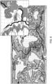
- the distributions of seismicity epicenters 500 is illustrated in Figure 5 and was compiled from publicly available sources.
- the sediment thickness and sediment type are factors that can help seal the subsurface geothermal system from cold ocean bottom waters, and so prevent excessive chilling of the geothermal reservoirs by convection and advection.
- the type of sediment can have a bearing on its sealing capacity.
- the thickness and character of the sediment can also affect its ability to insulate the geothermal reservoir from heat loss by thermal conduction. In some circumstances, the presence of a few hundred meters of sediment can assist with the initial drilling and setting of the casing. Thus, a good sediment with a reasonable thickness, for example, smaller than 3,000 m, has a high score contribution when the overall score for the selection of the well is calculated.
- vents both continuous and episodic, mostly show where hot geothermal fluids are rising through the ocean crust and sediments to discharge onto the sea bed.
- the known and unknown near-continuously erupting vents need to be mapped so they can be avoided because: they are potentially valuable sites for biological and chemical research, and they are likely to be cooling the geothermal system.
- Some vents have been visited and sampled, so their locations, fluid temperatures, chemistries and flow rates are known. The presence of others is inferred from the chemical "fingerprint" of vent fluids in the ocean water column. Less commonly, the flux to surface of nutrient-rich geothermal fluids has triggered algal blooms in surface waters that are large enough to be seen on satellite imagery.
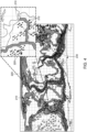
- FIG. 7 shows the use of synthetic aperture radar in key areas, to detect slicks that may represent biogenic or inorganic chemical sea surface expressions of leakage of geothermal waters. Based on this identification, corresponding ocean floor vents are determined.
- Figure 7 shows the axis of the ocean spreading centers 200, seepage slicks 710 of various ranks, and new unclassified slicks 720. Note that these slicks may in some cases represent episodic leakage of geothermal waters and thus, they provide an additional tool for exploring for underwater geothermal sites. This method indicates that such slicks are relatively common in the vicinity of some spreading centers 200. This is important since it suggests that open marine ecosystems are more likely to be adapted to fluxes of the nutrients in geofluids, as proposed here, than to contentious methods of ocean fertilization that have been attempted previously such as iron input [5].
- Each of the bathymetry and wave climate factors can have a high or low individual score.
- the water depth for a possible well location is less than 400 m, which means a high individual score.
- a water depth larger than 4,000 m is undesired because of the difficulties of placing a riser at such a depth.
- such a water depth would have a low individual score.
- the wave climate factors it is desired that the water surface is smooth and not affected by large waves, as the floating platform that sits at the selected site and all afferent components of the plant would be negatively affected by these waves.
- step 900 the method, which is implemented into a computing system, receives one or more data sets, e.g., the maps discussed above with regard to the figures.
- the data sets may be the maps shown in Figures 1 to 8 . In one application, all these maps are received as input. However, one skilled in the art would understand that less or more maps may be received, i.e., less factors may be considered, or additional factors may be considered, water temperature, rock permeability, etc.
- Each data set or map illustrates at least one factor, where the factor may be any one of the oceanic crust age, spreading centers, transform faults, volcanoes, seamounts, seismicity, ocean floor vents, sediment thickness, sediment type, bathymetry, or wave climate.
- Other factors may be considered, as for example, the water temperature at the ocean bottom, the ambient temperature (for example, it might be undesirable to have the plant in a very cold region), rock permeability, proximity to inhabited areas, the proximity to highly inhabited areas, the proximity to land, the type of coastal soil (for example, if the coast region is swampy, it is undesired to place cables and/or pipes into such an environment), etc.
- step 902 one or more of these factors is selected for being assigned an individual score.
- This process may be performed by the operator of the computing system, or by an automated software procedure, for example, neural network system.
- each factor is associated with a set of criteria, i.e., a set of rules. For example, if the factor is the seismicity, only earthquakes of magnitude 2 and greater, per 10,000 km 2 , over the 38 year-period to 2016, are considered. These earthquakes, which are shown in a corresponding map, may be associated with intervals or bins: for example, more than 200, between 200 and 100, between 100 and 10, between 10 and 1, and less than 1. These intervals or bins are exemplary and not intended to limit the invention. One skilled in the art could change the sizes of the intervals or bins as appropriate, based on hindsight from this application.
- step 906 the selected factors from step 902 are awarded individual scores, based on the data sets received in step 900, and also based on the criteria received in step 904.
- the individual scores of the selected factors for the screening process are then (polygonised) contoured, defining polygon areas of equal score, according to the criteria defined below.
- the polygon scores are summed, for example, in ArcGIS, to generate the overall exploration screening score.
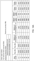
- the factors are scored (possible score values are in bold) as follows:
- the seismicity has the score 5: if more than 200 M2 earthquakes per 10,000 km 2 , over the 38 year-period to 2016, 4: for 200 to 100 M2 earthquakes, 3: for 100 to 10 M2 earthquakes, 2: for 10 to 1 M2 earthquakes, and 1: for less than one M2 earthquake;
- the age of the oceanic crust (in million years) is scored as 5: 0 to 6, 4: 6 to10, 3: 10 to 15, 2: 15 to 20, and 1: >20;
- the sediment thickness (m) is scored as 5: 300 to 1,000, 4: 50 to 300, 1,000 to 1,500, 3: 1,500 to 2,000, 2: 2,000 to 3000, and 1: >3000
- the bathymetry is scored (depth of ocean) as 5: 0 to 400, 4: 400 to 1,000, 3: 1,000 to 2,000, 2: 2,000 to 3,000, 1: 3,000 to 4,000, and 0: >4,000;
- the wave climate (m, maximum significant wave height in 12-year period) is scored as 5: 0 to 6, 3: 6 to 12, and 1: >12;
- the continuously active ocean floor vents (10 km buffer around the drilling site) is -28. This large and negative score is selected to ensure that such sites are not targeted as these zones are not stable, and they can be dangerous for the geothermal plant.
- the volcanoes, active and dormant, (10 km buffer around the drilling site) are scored as 2;
- the seamounts (10 km buffer around the drilling site) are scored as 1.
- the overall score is calculated in step 908.
- Various methods may be used for calculating the overall score.
- One is the software platform ArcGIS.
- Another one is using a function "f" that takes as input all the individual scores and outputs a single overall score.
- the function f may be a polynomial function, where each individual score is weighted with a given coefficient. In one application, the function f is simply the sum of all the individual scores.
- Other functions or software platforms may be used to combine the individual scores.
- mapping components are used to help guide interpretation of the polygon mapping in areas where data for seismicity and sediment thickness are considered insufficient: spreading centers, transform faults, and sediment type. This means, that even for the areas where not all the factors are available, the method can still calculate an overall score based on less factors.
- the function may have a variable number of factors, depending on the available data. However, in one embodiment, the function needs at least the spreading centers, transform faults, and sediment type data for calculating the overall score.
- the overall score is compared with a given threshold, and if the overall score is larger than the given threshold, the physical ocean location corresponding to the overall score is listed as a desired location for drilling the well and extracting the geothermal energy.
- the results from the integration of the map elements using the methodology described in Figure 9 can be used to predict potential geothermal resources that are ideal for exploration.
- the spreading center resource potential can be estimated using the resource density from an Iceland rift analogue of 35 MWe/km, which is illustrated in Figure 10 .
- the rift settings in Iceland are the closest onshore analogues to oceanic spreading centers on young oceanic crust. This analogue has been applied for the ocean crust areas less than 6 million years old, in water depths of less than 1,000 m, in areas where the maximum significant wave height for a 20 year period is less than 6 m.
- the potential resource result is 5,900 GWe, which is slightly more than the world's total annual electricity generation. If the water depth constraint is relaxed to 3,000 m, which is within the depth window of current hydrocarbon exploration and production, then the total potential resource rises to 67,000 GWe. Application of onshore analogues may underestimate the potential resource available in offshore settings.
- the production-related discussion presented next shows that there is potential upside to offshore geothermal from pumping high temperature fluids, which is not available in onshore settings.
- relatively large wellbores are available in deep water setting, which permit higher flow rates and therefore additionally has the potential to improve the energy flux rates per well.
- the following embodiments address this operational aspect of the geothermal production and introduce novel ways for extracting this energy from the crust.
- These embodiments are directed to at least four configurations: (1) an auxiliary riser diverting from the main riser below the onset depth for two-phase flow, to permit remediation of scale or corrosion without reduction in flow, (2) a valve method and system to use ocean water and ocean water pressure to sustain reservoir pressure without pumping, (3) a valve method and system to use geothermal brine and ocean water pressure to sustain reservoir pressure without pumping, and to suppress organic growth that might decrease injection permeability, and (4) an injector pattern method and system designed to evolve during production to maintain reservoir pressure and to improve thermal sweep between the gravity-driven injectors and the producer.
- the seabed vents demonstrate that the oceanic crust near the spreading centers is permeable, and numerous vent fields contain at least one system emitting fluids in the temperature range of 250 oC to 400 oC.
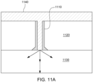
- Figure 11A schematically illustrates a vent wellbore 1110 that extends through sedimentary material 1120, which acts as a seal (for example, biogenic ooze), and connects the hot water from the geothermal reservoir 1130 to the cold ocean bottom water 1140.
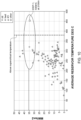
- Figure 11B shows the experimental measurements collected for the crust temperature as a function of the depth from the ocean bottom, and also the location 1150 of the estimated rate of inflow, i.e., 400 m depth.
- thermomechanical properties of recovered core samples during the drilling of oil and gas wells are available.
- the measured permeabilities and porosities in these samples are typically very low.
- core recovery from the upper part of the oceanic crust is generally less than 50%, which leaves open the question of what permeability is represented by the unrecovered cored intervals.
- the inventors' experience from the oil and gas exploration suggests that the unrecovered sections often represent the most permeable and porous sections of a cored rock sequence.
- Fluid injection tests though very limited in number, do indicate that permeability in the upper oceanic crust is significantly higher than would be inferred from the permeability measured on cores recovered from oceanic crust [7].
- the permeability of the intended zones to be drilled can also be used for determining whether to drill or not the well for reaching the geothermal resources.
- the use of software ordinarily applied to modelling permeabilities for oil and gas exploration in sedimentary basins was extended to include permeability in the oceanic crustal setting by collating and integrating published data on:
- Causes of these permeability changes can include, but are not limited to: (1) increases due to opening of permeability pathways by extension; (2) increases due to corrosion of rock along permeability pathways, (3) reductions due to closure of permeability pathways by compression, and (4) reductions due to mineral precipitation along permeability pathways.
- the geological processes driving these changes can include, but are not limited to: (1) permeability increase due to extension across faults and fractures by shrinkage of rock due to cooling of the crust with increasing distance from the oceanic spreading center, (2) permeability increase due to extensions across faults and fractures due to changes in the tectonic intra-plate stress regimes, (3) permeability decrease due to compression across faults and fractures due to increased loading by addition of overburden thickness, (4) compression across faults and fractures due to changes in the tectonic intra-plate stress regimes, (5) permeability increase, by dissolution of wall-rock minerals along permeability pathways by in-situ geofluids, or permeability decrease by mineral precipitation along permeability pathways from in-situ geofluids, may be triggered by cooling of crust and overlying sediments with increasing distance from the spreading center, (6) permeability increase, by dissolution of wall-rock minerals along permeability pathways by in-situ geofluids, or permeability decrease by mineral precipitation along
- thermo-mechanical responses of rocks, fluid flow rates and rates of heat transfer in different geological scenarios are modelled, for example, in CGG GeoSIM software (CGG, Paris).
- CGG GeoSIM software CGG, Paris
- other software platforms such as TOUGH 3 (tough.lbl.gov/software/tough3/) and Eclipse (www.software.slb.com/products/eclipse/fieldmgmt) may be able to undertake similar modelling.
- TOUGH 3 tough.lbl.gov/software/tough3/
- Eclipse www.software.slb.com/products/eclipse/fieldmgmt
- all the factors discussed above that influence the temperature gradients and the permeability of the crust may also be used with the method of Figure 9 for determining the overall score.
- the temperature gradients and the permeability of the crust are heavily weighted to influence the overall score as it is desired to have a high temperature gradient and a low permeability of the crust or sediment above the geothermal reservoir.
- FIG. 12 An offshore geothermal well configuration is illustrated in Figure 12 together with a geothermal plant 1200, that is configured to extract the heat from the geothermal reservoir and to transform it into other sources of energy.
- the plant 1200 may include a floating platform 1202, for example, boat, vessel, oil rig, barge, etc., which is large enough to support a power plant 1210.
- the power plant 1210 includes at least a separation unit 1212 that separates the incoming two-phase geofluid 1220 into steam 1222 and brine 1224.
- the liquid 1226 that is originally extracted from the geothermal reservoir 1230 is a single-phase liquid, as this single-phase liquid 1226 advances toward the ocean surface it cools down, reduces its pressure and at a certain ocean depth 1228 becomes the two-phase geofluid 1220.
- the depth 1228 below sea level at which the rising hot geothermal fluid will start to form steam depends mainly on the temperature, geofluid chemistry and geofluid pressure. The latter is particularly strongly affected by reservoir permeability and will deepen through time if the reservoir pressure is not maintained by reservoir injection, which is discussed later.
- the mechanical actuation part 1264 may include an impeller and a motor that rotates the impeller.
- the electrical part 1266 may include electronics that controls the motor and one or more sensors, e.g., temperature sensor.
- the electrical part 1266 is electrically connected to a power source located on the floating platform 1202, through an electrical cable 1268.
- the electrical cable 1268 may be used not only to send electrical power, but also commands and/or data.
- the electrical energy and/or signals from the electrical part 1266 travel to the mechanical actuation part 1264 either through induction, so that the wall of the riser is not perforated, or through an electrical wire (not shown) that enters inside the riser through a perforation (not shown).
- the electronics of the electrical pump 1260 can be located outside the riser 1240, where the temperature is low, about 4 °C, ensures that the pump would not fail as is the case inside a riser for oil and gas geothermal exploration, as the temperature inside the riser is typically very high. This means that the pump may be made as large as possible without concern about the extra heat generated by the mechanical actuation part 1264, as the ocean water would quickly absorb this extra heat.
- Figure 16 also shows a blow-out preventer 1612 installed at the ocean bottom, on the riser, so that if a sudden pressure increase in the riser is detected coming from the geothermal reservoir, the blow-out preventer can close the bore of the riser to prevent the pressure wave to reach the floating platform 1202.
- the pump 1260 and the blow-out preventer 1612 may be controlled with a computing device 1620 that is located on the floating platform.
- a switching valve 1622 is installed on the main raiser, below the ocean depth 1228 where the one-phase liquid 1226 transforms into the two-phase geofluid 1220.
- the switching valve 1622 can be electronically controlled by the computing device 1620, so that the fluid rising up the riser 1240 can be directed either into the upper part of the main raiser 1240 or the auxiliary riser 1610.
- Figure 16 also shows a configuration in which the liquid 1226 flows initially through the lower portion of the main riser 1240, up to the switching valve 1622, after which the liquid is diverted into the auxiliary riser 1610 while the upper part of the main riser 1240 is de-scaled, for example, by pressurized bleed.
- the depth range H of the placement of the pump 1260 is also shown in the figure.
- Intrusive igneous rocks are relatively brittle, and they will contain numerous natural joints and fractures due to shrinkage on cooling.
- the potential geothermal reservoirs 1230 also sit in relatively well understood present-day stress regimes. Owing to the thin and thermally weakened nature of the crust in these settings, natural seismicity is rarely above magnitude 5. Consequently, the deeper and hotter parts of the igneous reservoirs can be expected to respond well to fracture stimulation, with broadly predictable geometries, modest upper limits to magnitudes of induced seismicity, at locations that are relatively remote from population centers.
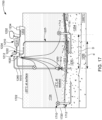
- FIG. 17 show such a configuration in which gravity feed valves 1710, 1714 offer reservoir pressure and flow control to corresponding gravity feed pipes 1712, 1716. Flow control could be needed, for example, if an unexpected high permeability zone allowed cool water to reach the riser. For this reason, the gravity feed valves 1710 and 1716 are also controlled by the computing device 1620.
- the gravity feed pipes 1712 and 1716 extend into the ocean water just enough to capture the cold ocean water 1724 (having a temperature around 3 °C and a density of about 1002 kg/m 3 ) and they are capped with the corresponding valves 1710 and 1714. Because the water density around the head of the pipes 1712 and 1714 is about 1002 kg/m 3 and the density of the water in the geothermal reservoir 1230 is about 820 kg/m 3 , by simply opening the valves 1710 and 1714, the cold water 1724 enters inside the gravity feed pipes and move into the geothermal reservoirs entirety due to the gravity, i.e., because of the weight difference between the cold and hot water.
- the gravity feed pipes 1712, 1716 are places in wells drilled at least a distance D from the main riser 1240, where the distance D is selected so that the cold water 1724 has enough time to heat to 200 to 300 °C before reaching the riser 1240.
- the gravity feed rates through the gravity feed pipes can be controlled by the corresponding valves 1710 and 1714, to reconcile the reservoir permeability and geofluid pressure drawdown at the riser.
- the ocean water inlet or heads of the gravity feed pipes 1712 and 1716 are raised above the ocean bottom 1720 to avoid "catching" mobile benthic organisms or sea-bed mud plumes carried by bottom currents.
- the inlet can be fitted with a filter (grid) designed to exclude pelagic organisms. This framework could become a site for growth of sessile organisms. Such growth is a relatively slow process in deep water settings, but could be suppressed by flushing with high salinity geothermal brine.
- Figure 17 further show that the brine 1224 separated from the two-phase fluid 1220 by the power plant 1210 can be discharged through a corresponding brine pipe 1225 closer to or into the geothermal reservoir 1230, i.e., a well is drilled into the reservoir or the crust and the brine pipe 1225 enters inside this well so that the pipe enters a given length into the crust, as shown in Figure 17 .
- the temperature of the brine 1224 is between 40 to 60 °C
- the distance d between the brine pipe 1225 and the main riser 1240 is smaller than the distance D between the gravity feed pipe 1710 and the main riser 1240. This is so because the warm brine 1224 would need less time to heat back to 200 to 300 °C, to reach the geothermal reservoir's temperature.
- the geothermal brine 1224 that results when separating the steam 1222 can be disposed without pumping as now discussed with regard to the embodiment of Figure 18 .
- the plant 1800 in this figure uses a brine tank 1810 that is located around the head of the gravity feed pipe 1712.
- the brine tank 1810 is sized and positioned so that the entire switching valve 1710 sits inside the brine tank, as shown in the figure.
- the brine tank is installed on the ocean bottom.
- the brine pipe 1225 is extended with a horizontal pipe 1812 to fluidly connect to the brine tank 1810.
- a valve 1814 is provided between the pipe 1812 and the tank 1810 to control the flow of the brine 1224 into the brine tank 1810.
- the valve 1814 is electronically controlled by the computing device 1620.
- the upper surface of the tank 1810 is open so that the ocean water 1724 can freely enter into the tank.
- the brine 1224 can be directly added into the gravity feed pipe 1712 from the brine tank 1814, with valve control, either via the pipe 1812 or via an artificial brine pool.
- the rim 181 0A of the brine pool 1810 is designed to be higher than the inlet level for the ocean water into the pipe 1712. This gives the option, by reducing the flow through the inlet valve 1710 and increasing the flow through the brine valve 1814, to raise the level of the brine 1224 into the brine pool 1810 to cover the oceanic inlet area with brine, from time to time.
- This action could be used to suppress any organic growth that might form on the oceanic water inlet and, because the injected fluid during this operation would be a high salinity brine, this would also suppress formation of any organic films in the injection zone of the reservoir 1230. Note that no pumping is necessary for the brine flow as the gravity is responsible for the brine movement, as the brine is relatively dense.
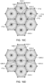
- Figure 19A shows a triangular pattern, in which three gravity feed pipes 1712-1 to 1712-3 are placed at the corners of an equilateral triangle 1900, which is centered on the riser 1240.
- the three pipes 1712-1 to 1712-3 inject the cold brine at a cold temperature C, while the riser 1240 extracts the hot geothermal liquid 1226 at a hot temperature H, where C could be between 40 and 60 °C and the H could be between 200 and 300 °C. Other values may be used.
- the cold brine pushes or sweeps the hot liquid 1226 from the corners of the triangle 1900 toward its center, where the riser 1240 is extracting the hot geothermal liquid.
- FIG. 19B illustrates a hexagonal cell or pattern 1910 as shown in Figure 19B .
- Other geometrical shapes may be used to place the pipes 1712.
- Figure 19C illustrates another configuration in which the hexagonal cell 1910-I is repeated so that two adjacent cells share two pipes 1712. Using this configuration, it is possible to turn off one riser 1240-3 in one cell 1910-3, but to leave open all other risers 1240-I. This may be helpful when the geothermal liquid 1226 in that cell is too cold, and the cell needs more time to heat up the liquid to return to a productive temperature.
- the plant 2000 shown in Figure 20 which includes various components from the plants previously discussed, has the capability of storing and permanently fixing carbon dioxide by mineralization in repurposed offshore geothermal wells. Note that some of the elements of the previous plants are omitted herein, but the plant 2000 can have each of the elements of the previous plants.
- Regarding carbon dioxide for the temperature range of 25oC to 0 oC, the carbon dioxide changes from gas to liquid at modest pressures. Liquid carbon dioxide is more compressible than water, so at high pressures, equivalent to ocean depths in excess of 2500 m, the liquid carbon dioxide is denser than the sea water 1724. This means that carbon dioxide storage systems (wells) in deep water will be robust since they are not required to retain a buoyancy force.
- Carbon dioxide is more soluble in cold water than in hot water, and so will tend to react with relatively hot rocks to form minerals. Basalts are particularly good hosts for carbon dioxide reactions, typically forming carbonate minerals at relatively rapid rates. This combination of robust storage and rapid mineralization offers an additional application for offshore geothermal wells that are not delivering geothermal fluids at sufficient flow rates or high enough temperatures.
- FIG 20 shows that used steam 2010 from the heat conversion unit 1231 can be used in various ways.
- One way is to condense the steam into a cooling pipe 2020 that extends from the floating platform 1202 into the ocean water 1724 and generate fresh water, which can be delivered directly to land through the pipe 2020, as shown in the figure, or pumped back on the floating platform and stored in a fresh water tank 2021 there. If the floating platform is close to land, then there is no need to pump the used steam 2010 into the pipe 2020.
- Another option is to use the used steam 2010 and the generated electrical power 2014 for electrolysis, in an electrolysis module 2030, to generate hydrogen H 2 and oxygen O 2 .
- the hydrogen may be used in a reactor 2032 to convert it to ammonia, which is stored on board into an ammonia tank 2034.
- the hydrogen may be stored by itself in a hydrogen tank 2036.
- the generated oxygen may be used to enhance fish population, either by pumping it directly into the ocean, or into a fish tank 2038 that may be located on the floating platform or linked to the floating platform.
- Brine 1224 may also be deviated along a dedicated pipe 2040 to the fish tank 2038 so that nutrients are brought into the tank.
- minerals and/or chemicals from the brine 1224 may be extracted on board and stored into a mineral tank 2042.
- Carbon dioxide from a tank 2044 or ambient can be pumped with a pump 2046 along a carbon dioxide pipe 2048 that extends from the floating platform to a well 2056 formed into the crust 1250.
- the carbon dioxide 2052 gas As the carbon dioxide 2052 gas enters the pipe 2048 it starts to cool down due to the low temperature of the ocean water, until becoming liquid carbon dioxide 2054. As the liquid carbon dioxide 2054 is denser than the ocean water 1724, the liquid carbon dioxide can be easily discharged into one or more wells 2056, where it interacts with the existing rock and mineralizes for easy storage.
- the temperature and permeability of the various structures and the flow of fluids discussed herein can be modeled to anticipate the size of the plant and its efficiency.
- the following reference horizons are mapped with a software platform:
- the predictive mapping of modelled permeability distributions uses the following reference horizons:
- Permeabilities attributed to fractures and faults are superimposed upon the basic multi-layer rock property model.
- the conceptual geological fracture and fault models, plus the insights from thermomechanical models of permeability, form the main basis of this attribution. Assignment of these permeabilities may be:
- Present-day stress regime data is obtained from: (1) boreholes, including image log analysis of wellbores, oriented caliper data, fracture analysis on oriented cores, (2) first motion analysis of seismicity in combination with mapped fault and fracture orientations, (3) plate motions from GPS analysis, and (4) relative plate motions from the plate model.
- boreholes including image log analysis of wellbores, oriented caliper data, fracture analysis on oriented cores, (2) first motion analysis of seismicity in combination with mapped fault and fracture orientations, (3) plate motions from GPS analysis, and (4) relative plate motions from the plate model.
- the power resource estimates based on the exploration screening part of this disclosure demonstrates that that just one part of the underwater geothermal resource is of sufficient magnitude to have a material impact on helping the world reach net zero carbon dioxide by 2050.
- the Earth's huge underwater geothermal energy resources could also provide fresh water and nutrients as beneficial by-products which can help mitigate the World's freshwater deficits and depleted fish stocks.
- An additional environmental benefit of geothermal exploration is that it has a relatively low demand, per unit of power generated, for other Earth resources compared with other sources of green energy.
- Use of Earth resources for mining and production of materials such as concrete, cement, steel, glass, plastics, composites and critical metals can have the effect of creating a large carbon footprint in another industry.
- the greater efficiencies likely to accrue from application of oil and gas industry technologies, using the new methods and plants described here, may mean that the resource demand, per unit of power generated, of underwater geothermal may be no greater than that of current geothermal onshore.
- the potential benefits of scale could mean that resource demand per unit of power generated, would reduce over time. This, combined with the potential for valuable by-products such as fresh water and nutrients, the value of commercial and geographic flexibility, with no imposition on land use, could result in underwater geothermal making a major contribution to sustainable development on this planet.
- the method includes a step 2100 of placing a first end of a riser into a well drilled into the geothermal reservoir, a step 2102 of connecting a second end of the riser to a floating platform, a step 2104 of actuating an electrical pump, which has a mechanical actuation part located in a bore of the riser, and an electronic part located outside the riser, to pump a geothermal liquid from the geothermal reservoir to the floating platform, and using steam from the geothermal liquid to generate electrical power with a power plant located on the floating platform.
- the electrical pump is placed at a depth of the riser where the geothermal liquid is in a single-phase.
- the method may also include a step of placing a first end of a brine pipe into the geothermal reservoir, a step of connecting a second end of the brine pipe to the floating platform, and a step of discharging a brine from the geothermal liquid into or next to the geothermal reservoir through the brine pipe with no pump as the brine flows due exclusively to the gravity into the geothermal reservoir.
- the method may further include a step of separating the steam from the brine of the geothermal liquid with a separator located on the floating platform; and a step of storing the electrical power in an electrical storage unit located on the floating platform.
- the method may include a step of attaching a switching valve on the riser, below a position where the single-phase geothermal liquid becomes a two-phase geofluid, and a step of connecting an auxiliary riser with one end to the switching valve and with another end to the floating platform, wherein the single-phase geothermal liquid flows only through the riser when the switching valve is in a first state and through a lower part of the riser and the auxiliary riser when the switching valve is in a second state.
- the method may further include a step of installing a gravity feed pipe with one end into the geothermal reservoir, away from the riser, and a step of installing a gravity feed valve on a head of the gravity feed pipe to allow ocean water to enter into the gravity feed pipe and into the geothermal reservoir exclusively due to the gravity.
- the method may also include a step of placing an open brine tank on the ocean bottom, around the gravity feed pipe, so that the gravity feed valve is fully inside the brine tank, a step of connecting a brine pipe with one end to the floating platform and with another end to the open brine tank, and a step of discharging a brine from the geothermal liquid into the open brine tank.
- the disclosed embodiments provide a geothermal plant for generating energy from a geothermal reservoir located under the ocean bottom. It should be understood that this description is not intended to limit the invention. On the contrary, the embodiments are intended to cover alternatives, modifications and equivalents, which are included in the spirit and scope of the invention as defined by the appended claims. Further, in the detailed description of the embodiments, numerous specific details are set forth in order to provide a comprehensive understanding of the claimed invention. However, one skilled in the art would understand that various embodiments may be practiced without such specific details.
Landscapes
- Engineering & Computer Science (AREA)
- Life Sciences & Earth Sciences (AREA)
- Chemical & Material Sciences (AREA)
- Sustainable Energy (AREA)
- Sustainable Development (AREA)
- Combustion & Propulsion (AREA)
- Mechanical Engineering (AREA)
- General Engineering & Computer Science (AREA)
- Geology (AREA)
- Environmental & Geological Engineering (AREA)
- Chemical Kinetics & Catalysis (AREA)
- Mining & Mineral Resources (AREA)
- Hydrology & Water Resources (AREA)
- Fluid Mechanics (AREA)
- General Life Sciences & Earth Sciences (AREA)
- Metallurgy (AREA)
- Physics & Mathematics (AREA)
- Inorganic Chemistry (AREA)
- Materials Engineering (AREA)
- Electrochemistry (AREA)
- Organic Chemistry (AREA)
- Geochemistry & Mineralogy (AREA)
- Geophysics And Detection Of Objects (AREA)
- Earth Drilling (AREA)
- Other Liquid Machine Or Engine Such As Wave Power Use (AREA)
- Filling Or Discharging Of Gas Storage Vessels (AREA)
- Drilling And Exploitation, And Mining Machines And Methods (AREA)
Applications Claiming Priority (3)
| Application Number | Priority Date | Filing Date | Title |
|---|---|---|---|
| US202163171169P | 2021-04-06 | 2021-04-06 | |
| PCT/IB2022/000131 WO2022214867A1 (en) | 2021-04-06 | 2022-03-11 | Geothermal plant for extracting energy from a geothermal reservoir located below the ocean bottom |
| EP22715695.7A EP4320394B1 (de) | 2021-04-06 | 2022-03-11 | Geothermische anlage zur gewinnung von energie aus einem unterhalb des meeresbodens befindlichen geothermischen reservoir |
Related Parent Applications (2)
| Application Number | Title | Priority Date | Filing Date |
|---|---|---|---|
| EP22715695.7A Division-Into EP4320394B1 (de) | 2021-04-06 | 2022-03-11 | Geothermische anlage zur gewinnung von energie aus einem unterhalb des meeresbodens befindlichen geothermischen reservoir |
| EP22715695.7A Division EP4320394B1 (de) | 2021-04-06 | 2022-03-11 | Geothermische anlage zur gewinnung von energie aus einem unterhalb des meeresbodens befindlichen geothermischen reservoir |
Publications (3)
| Publication Number | Publication Date |
|---|---|
| EP4474728A2 true EP4474728A2 (de) | 2024-12-11 |
| EP4474728A3 EP4474728A3 (de) | 2025-02-19 |
| EP4474728B1 EP4474728B1 (de) | 2025-10-22 |
Family
ID=81328443
Family Applications (2)
| Application Number | Title | Priority Date | Filing Date |
|---|---|---|---|
| EP22715695.7A Active EP4320394B1 (de) | 2021-04-06 | 2022-03-11 | Geothermische anlage zur gewinnung von energie aus einem unterhalb des meeresbodens befindlichen geothermischen reservoir |
| EP24208190.9A Active EP4474728B1 (de) | 2021-04-06 | 2022-03-11 | Verfahren zur schätzung eines ortes auf dem ozeanboden für die bohrung eines bohrlochs zur erkundugung eines geothermischen reservoirs |
Family Applications Before (1)
| Application Number | Title | Priority Date | Filing Date |
|---|---|---|---|
| EP22715695.7A Active EP4320394B1 (de) | 2021-04-06 | 2022-03-11 | Geothermische anlage zur gewinnung von energie aus einem unterhalb des meeresbodens befindlichen geothermischen reservoir |
Country Status (10)
| Country | Link |
|---|---|
| US (2) | US12264851B2 (de) |
| EP (2) | EP4320394B1 (de) |
| JP (1) | JP2024513163A (de) |
| CN (1) | CN117098957A (de) |
| AU (1) | AU2022252974A1 (de) |
| BR (1) | BR112023017735A2 (de) |
| ES (2) | ES3059179T3 (de) |
| MX (1) | MX2023010884A (de) |
| PT (2) | PT4474728T (de) |
| WO (1) | WO2022214867A1 (de) |
Families Citing this family (3)
| Publication number | Priority date | Publication date | Assignee | Title |
|---|---|---|---|---|
| FR3100606B1 (fr) * | 2019-09-11 | 2022-05-06 | Constance Energy Sas | Aide à la réalisation d’une installation géothermique pour le confort thermique d’au moins un bâtiment |
| EP4435228B1 (de) * | 2023-03-22 | 2026-02-18 | Services Pétroliers Schlumberger | Verfahren zur herstellung eines geothermischen bohrlochs |
| US12546189B2 (en) | 2024-05-16 | 2026-02-10 | Schlumberger Technology Corporation | Ground-source thermal system for rejecting data center waste heat to a facility |
Family Cites Families (15)
| Publication number | Priority date | Publication date | Assignee | Title |
|---|---|---|---|---|
| NL7602387A (nl) * | 1976-03-08 | 1977-09-12 | Nkf Kabel Bv | Installatie voor het drogen en ontgassen van olie, in het bijzonder kabelolie. |
| US4059959A (en) * | 1976-11-05 | 1977-11-29 | Sperry Rand Corporation | Geothermal energy processing system with improved heat rejection |
| IT1123455B (it) * | 1979-07-03 | 1986-04-30 | Giunio Santi Guido | Centrale termoelettrica alimentata da una fonte di calore geotermica |
| US4370860A (en) * | 1980-06-03 | 1983-02-01 | Solmat | Method of and means for generating power from a hot brine source |
| US6073448A (en) * | 1998-08-27 | 2000-06-13 | Lozada; Vince M. | Method and apparatus for steam generation from isothermal geothermal reservoirs |
| DE10343544B4 (de) * | 2003-09-19 | 2008-05-08 | Pflanz, Tassilo, Dipl.-Ing. | Kraftwerksanlage zur Nutzung der Wärme eines geothermischen Reservoirs |
| WO2006029112A1 (en) * | 2004-09-08 | 2006-03-16 | Sovani Meksvanh | Solar augmented geothermal energy |
| DE102006062679A1 (de) * | 2006-12-28 | 2008-07-03 | Kayser, Christoph, Dipl.-Geol. | Verfahren zur Erkundung von Standorten zur Nutzung von Erdwärme für die Energieversorgung |
| US20100000214A1 (en) * | 2008-07-03 | 2010-01-07 | Lockheed Martin Corporation | Petroleum-based Thermoelectric Energy Conversion System |
| US20100043433A1 (en) * | 2008-08-19 | 2010-02-25 | Kelly Patrick J | Heat Balancer for Steam-Based Generating Systems |
| US8215104B2 (en) * | 2008-09-29 | 2012-07-10 | William Riley | Energy from subterranean reservoir fluid |
| JP2011069207A (ja) * | 2009-08-19 | 2011-04-07 | Hiroyasu Tanigawa | 各種エネルギ保存サイクル合体機関 |
| KR20120130210A (ko) | 2010-02-13 | 2012-11-29 | 맥알리스터 테크놀로지즈 엘엘씨 | 열전달 장치, 및 관련 시스템과 방법 |
| GB2539026A (en) * | 2015-06-04 | 2016-12-07 | Green Energy Group As | Geothermal steam processing |
| DE102017001055A1 (de) * | 2016-09-28 | 2018-03-29 | Ingo Daude | Energiegewinnung aus Wärmequellen auf dem Meeresgrund |
-
2022
- 2022-03-11 ES ES24208190T patent/ES3059179T3/es active Active
- 2022-03-11 JP JP2023557770A patent/JP2024513163A/ja active Pending
- 2022-03-11 ES ES22715695T patent/ES3017071T3/es active Active
- 2022-03-11 PT PT242081909T patent/PT4474728T/pt unknown
- 2022-03-11 MX MX2023010884A patent/MX2023010884A/es unknown
- 2022-03-11 WO PCT/IB2022/000131 patent/WO2022214867A1/en not_active Ceased
- 2022-03-11 CN CN202280026367.3A patent/CN117098957A/zh active Pending
- 2022-03-11 PT PT227156957T patent/PT4320394T/pt unknown
- 2022-03-11 EP EP22715695.7A patent/EP4320394B1/de active Active
- 2022-03-11 AU AU2022252974A patent/AU2022252974A1/en active Pending
- 2022-03-11 US US18/262,063 patent/US12264851B2/en active Active
- 2022-03-11 EP EP24208190.9A patent/EP4474728B1/de active Active
- 2022-03-11 BR BR112023017735A patent/BR112023017735A2/pt active Search and Examination
-
2024
- 2024-09-06 US US18/826,262 patent/US20240426521A1/en active Pending
Non-Patent Citations (8)
| Title |
|---|
| ALLSOPP, M.SANTILLO, D.JOHNSTON, P.: "A scientific critique of oceanic iron fertilization as a climate change mitigation strategy", GREENPEACE RESEARCH LABORATORIES TECHNICAL NOTE 07/2007, 2007 |
| BECKER K.FISHER, A.TSUJI, T.: "New packer experiments and borehole logs in upper oceanic crust: Evidence for ridge-parallel consistency in crustal hydrogeological properties", GEOCHEM. GEOPHYS. GEOSYST., vol. 14, 2013, pages 2900 - 2915 |
| HIRIART, GPROL-LEDESMA, R. M.ALCOCER, SESPINDOLA, S.: "2010. Submarine Geothermics; Hydrothermal Vents and Electricity Generation.", PROCEEDINGS WORLD GEOTHERMAL CONGRESS, 2010 |
| HIRIAT, G.CHAVEZ, I. M., 2021 SUBMARINE GEOTHERMAL GENERATION WORLD GEOTHERMAL CONGRESS, 2021 |
| KIMWESSEL: "New global seamount census from altimetry-derived gravity data", GEOGRAPHICAL JOURNAL INTERNATIONAL, vol. 186, 2011, pages 615 - 631 |
| SANYAL S. K.MORROW, J. M.BUTLER, S. J.: "Net power capacity of geothermal wells versus reservoir temperature - a practical perspective.", PROCEEDINGS, THIRTY-SECOND WORKSHOP ON GEOTHERMAL RESERVOIR ENGINEERING, STANFORD UNIVERSITY, STANFORD, CALIFORNIA, 2007 |
| SCHNELL, JHIRIART, GNICHOLS, KORCUTT, J., ENERGY FROM OCEAN FLOOR GEOTHERMAL RESOURCES., 2015, Retrieved from the Internet <URL:www.oceangeothermal.org/wp-content/uploads/2015/05/OGEF-Energy-from-Ocean-Floor-Geothermal-Resources.pdf> |
| TJETLAND, G.: "How can a ship be used to harvest energy?", NOR-SHIPPING 2022, 2017 |
Also Published As
| Publication number | Publication date |
|---|---|
| ES3059179T3 (en) | 2026-03-19 |
| EP4320394B1 (de) | 2024-12-18 |
| US20240085065A1 (en) | 2024-03-14 |
| JP2024513163A (ja) | 2024-03-22 |
| PT4320394T (pt) | 2025-03-17 |
| BR112023017735A2 (pt) | 2023-11-07 |
| US12264851B2 (en) | 2025-04-01 |
| AU2022252974A1 (en) | 2023-09-21 |
| CN117098957A (zh) | 2023-11-21 |
| ES3017071T3 (en) | 2025-05-12 |
| PT4474728T (pt) | 2026-01-05 |
| MX2023010884A (es) | 2023-09-27 |
| EP4474728A3 (de) | 2025-02-19 |
| EP4320394A1 (de) | 2024-02-14 |
| EP4474728B1 (de) | 2025-10-22 |
| WO2022214867A1 (en) | 2022-10-13 |
| US20240426521A1 (en) | 2024-12-26 |
Similar Documents
| Publication | Publication Date | Title |
|---|---|---|
| US20240426521A1 (en) | Geothermal plant for extracting energy from a geothermal reservoir located below the ocean bottom | |
| Jolie et al. | Geological controls on geothermal resources for power generation | |
| Liu et al. | Progress in global gas hydrate development and production as a new energy resource | |
| Patel | Dynamics of offshore structures | |
| Taylor et al. | A novel sub-seabed CO2 release experiment informing monitoring and impact assessment for geological carbon storage | |
| Halland et al. | Evaluation of CO2 storage possibilities on the Norwegian Continental Shelf | |
| Bakken et al. | Submarine groundwater: A new concept for the supply of drinking water | |
| Wan et al. | Dissociation of gas hydrates by hydrocarbon migration and accumulation-derived slope failures: An example from the South China Sea | |
| Arnórsson et al. | Utilization of geothermal resources | |
| Anderson | Oil production in the 21st century | |
| Hulen et al. | Refined conceptual modeling and a new resource estimate for the Salton Sea geothermal field, Imperial Valley, California | |
| Shinn et al. | 3D grid based screening process for large-scale CO2 geological storage in Gunsan Basin, Yellow Sea, Korea | |
| Dutcher et al. | Preliminary appraisal of ground water in storage with reference to geothermal resources in the Imperial Valley area, California | |
| BR122025004534A2 (pt) | Método para estimar um local no fundo do oceano para perfurar um poço de exploração | |
| Hubberten et al. | The main features of permafrost in the Laptev Sea region, Russia-a review | |
| Sigurdsson | The Reykjanes seawater geothermal system–Its exploitation under regulatory constraints | |
| Shaban et al. | The geological controls of geothermal groundwater sources in Lebanon | |
| Max et al. | The dynamic oceanic hydrate system: production constraints and strategies | |
| Exon et al. | The opening of the Tasmanian gateway drove global Cenozoic paleoclimatic and paleoceanographic changes: results of Leg 189 | |
| Goodwin | The future of oil and gas fossil fuels | |
| Dashdamirli | Abandoned oil and gas wells in sedimentary basins as sustainable sources of geothermal energy | |
| Bromley | Groundwater Changes in the Wairakei–Tauhara Geothermal System | |
| Fairley et al. | Sub-seafloor carbon dioxide storage potential on the Juan de Fuca Plate, Western North America | |
| Michalopoulos | Fire from ice in the Eastern Mediterranean: the potential role of gas hydrates in the EU energy mix | |
| Hickson et al. | Alberta’s Western Canada Sedimentary Basin’s First Electrical Geothermal Project |
Legal Events
| Date | Code | Title | Description |
|---|---|---|---|
| PUAI | Public reference made under article 153(3) epc to a published international application that has entered the european phase |
Free format text: ORIGINAL CODE: 0009012 |
|
| STAA | Information on the status of an ep patent application or granted ep patent |
Free format text: STATUS: THE APPLICATION HAS BEEN PUBLISHED |
|
| AC | Divisional application: reference to earlier application |
Ref document number: 4320394 Country of ref document: EP Kind code of ref document: P |
|
| AK | Designated contracting states |
Kind code of ref document: A2 Designated state(s): AL AT BE BG CH CY CZ DE DK EE ES FI FR GB GR HR HU IE IS IT LI LT LU LV MC MK MT NL NO PL PT RO RS SE SI SK SM TR |
|
| PUAL | Search report despatched |
Free format text: ORIGINAL CODE: 0009013 |
|
| AK | Designated contracting states |
Kind code of ref document: A3 Designated state(s): AL AT BE BG CH CY CZ DE DK EE ES FI FR GB GR HR HU IE IS IT LI LT LU LV MC MK MT NL NO PL PT RO RS SE SI SK SM TR |
|
| RIC1 | Information provided on ipc code assigned before grant |
Ipc: F24T 50/00 20180101AFI20250116BHEP |
|
| STAA | Information on the status of an ep patent application or granted ep patent |
Free format text: STATUS: REQUEST FOR EXAMINATION WAS MADE |
|
| 17P | Request for examination filed |
Effective date: 20250402 |
|
| GRAP | Despatch of communication of intention to grant a patent |
Free format text: ORIGINAL CODE: EPIDOSNIGR1 |
|
| STAA | Information on the status of an ep patent application or granted ep patent |
Free format text: STATUS: GRANT OF PATENT IS INTENDED |
|
| INTG | Intention to grant announced |
Effective date: 20250604 |
|
| GRAS | Grant fee paid |
Free format text: ORIGINAL CODE: EPIDOSNIGR3 |
|
| GRAA | (expected) grant |
Free format text: ORIGINAL CODE: 0009210 |
|
| STAA | Information on the status of an ep patent application or granted ep patent |
Free format text: STATUS: THE PATENT HAS BEEN GRANTED |
|
| AC | Divisional application: reference to earlier application |
Ref document number: 4320394 Country of ref document: EP Kind code of ref document: P |
|
| AK | Designated contracting states |
Kind code of ref document: B1 Designated state(s): AL AT BE BG CH CY CZ DE DK EE ES FI FR GB GR HR HU IE IS IT LI LT LU LV MC MK MT NL NO PL PT RO RS SE SI SK SM TR |
|
| P01 | Opt-out of the competence of the unified patent court (upc) registered |
Free format text: CASE NUMBER: UPC_APP_7140_4474728/2025 Effective date: 20250915 |
|
| REG | Reference to a national code |
Ref country code: CH Ref legal event code: F10 Free format text: ST27 STATUS EVENT CODE: U-0-0-F10-F00 (AS PROVIDED BY THE NATIONAL OFFICE) Effective date: 20251022 Ref country code: GB Ref legal event code: FG4D |
|
| REG | Reference to a national code |
Ref country code: DE Ref legal event code: R096 Ref document number: 602022023711 Country of ref document: DE |
|
| REG | Reference to a national code |
Ref country code: IE Ref legal event code: FG4D |
|
| REG | Reference to a national code |
Ref country code: DE Ref legal event code: R082 Ref document number: 602022023711 Country of ref document: DE Representative=s name: NUSS, LAURENT VALENTIN, DIPL.-ING. (ETHZ), MAS, DE |
|
| REG | Reference to a national code |
Ref country code: PT Ref legal event code: SC4A Ref document number: 4474728 Country of ref document: PT Date of ref document: 20260105 Kind code of ref document: T Free format text: AVAILABILITY OF NATIONAL TRANSLATION Effective date: 20251226 |
|
| REG | Reference to a national code |
Ref country code: NL Ref legal event code: FP |
|
| REG | Reference to a national code |
Ref country code: ES Ref legal event code: FG2A Ref document number: 3059179 Country of ref document: ES Kind code of ref document: T3 Effective date: 20260319 |
|
| PGFP | Annual fee paid to national office [announced via postgrant information from national office to epo] |
Ref country code: GB Payment date: 20260324 Year of fee payment: 5 |
|
| REG | Reference to a national code |
Ref country code: LT Ref legal event code: MG9D |
|
| PGFP | Annual fee paid to national office [announced via postgrant information from national office to epo] |
Ref country code: NO Payment date: 20260323 Year of fee payment: 5 Ref country code: DE Payment date: 20260319 Year of fee payment: 5 |
|
| PG25 | Lapsed in a contracting state [announced via postgrant information from national office to epo] |
Ref country code: FI Free format text: LAPSE BECAUSE OF FAILURE TO SUBMIT A TRANSLATION OF THE DESCRIPTION OR TO PAY THE FEE WITHIN THE PRESCRIBED TIME-LIMIT Effective date: 20251022 Ref country code: AT Free format text: LAPSE BECAUSE OF FAILURE TO SUBMIT A TRANSLATION OF THE DESCRIPTION OR TO PAY THE FEE WITHIN THE PRESCRIBED TIME-LIMIT Effective date: 20251022 Ref country code: HR Free format text: LAPSE BECAUSE OF FAILURE TO SUBMIT A TRANSLATION OF THE DESCRIPTION OR TO PAY THE FEE WITHIN THE PRESCRIBED TIME-LIMIT Effective date: 20251022 |
|
| PGFP | Annual fee paid to national office [announced via postgrant information from national office to epo] |
Ref country code: AT Payment date: 20260301 Year of fee payment: 5 |
|
| PGFP | Annual fee paid to national office [announced via postgrant information from national office to epo] |
Ref country code: IT Payment date: 20260324 Year of fee payment: 5 |
|
| REG | Reference to a national code |
Ref country code: AT Ref legal event code: MK05 Ref document number: 1849451 Country of ref document: AT Kind code of ref document: T Effective date: 20251022 |
|
| PGFP | Annual fee paid to national office [announced via postgrant information from national office to epo] |
Ref country code: NL Payment date: 20260319 Year of fee payment: 5 |
|
| PG25 | Lapsed in a contracting state [announced via postgrant information from national office to epo] |
Ref country code: RS Free format text: LAPSE BECAUSE OF FAILURE TO SUBMIT A TRANSLATION OF THE DESCRIPTION OR TO PAY THE FEE WITHIN THE PRESCRIBED TIME-LIMIT Effective date: 20260122 |
|
| PGFP | Annual fee paid to national office [announced via postgrant information from national office to epo] |
Ref country code: IS Payment date: 20260311 Year of fee payment: 5 Ref country code: FR Payment date: 20260323 Year of fee payment: 5 |
|
| PGFP | Annual fee paid to national office [announced via postgrant information from national office to epo] |
Ref country code: PT Payment date: 20260226 Year of fee payment: 5 |
|
| PG25 | Lapsed in a contracting state [announced via postgrant information from national office to epo] |
Ref country code: PL Free format text: LAPSE BECAUSE OF FAILURE TO SUBMIT A TRANSLATION OF THE DESCRIPTION OR TO PAY THE FEE WITHIN THE PRESCRIBED TIME-LIMIT Effective date: 20251022 |
|
| PG25 | Lapsed in a contracting state [announced via postgrant information from national office to epo] |
Ref country code: LV Free format text: LAPSE BECAUSE OF FAILURE TO SUBMIT A TRANSLATION OF THE DESCRIPTION OR TO PAY THE FEE WITHIN THE PRESCRIBED TIME-LIMIT Effective date: 20251022 |