EP4474715A1 - Cooking apparatus - Google Patents
Cooking apparatus Download PDFInfo
- Publication number
- EP4474715A1 EP4474715A1 EP22925091.5A EP22925091A EP4474715A1 EP 4474715 A1 EP4474715 A1 EP 4474715A1 EP 22925091 A EP22925091 A EP 22925091A EP 4474715 A1 EP4474715 A1 EP 4474715A1
- Authority
- EP
- European Patent Office
- Prior art keywords
- door
- air guide
- air
- disposed
- guide
- Prior art date
- Legal status (The legal status is an assumption and is not a legal conclusion. Google has not performed a legal analysis and makes no representation as to the accuracy of the status listed.)
- Pending
Links
Images












Classifications
-
- F—MECHANICAL ENGINEERING; LIGHTING; HEATING; WEAPONS; BLASTING
- F24—HEATING; RANGES; VENTILATING
- F24C—DOMESTIC STOVES OR RANGES ; DETAILS OF DOMESTIC STOVES OR RANGES, OF GENERAL APPLICATION
- F24C15/00—Details
- F24C15/006—Arrangements for circulation of cooling air
-
- F—MECHANICAL ENGINEERING; LIGHTING; HEATING; WEAPONS; BLASTING
- F24—HEATING; RANGES; VENTILATING
- F24C—DOMESTIC STOVES OR RANGES ; DETAILS OF DOMESTIC STOVES OR RANGES, OF GENERAL APPLICATION
- F24C14/00—Stoves or ranges having self-cleaning provisions, e.g. continuous catalytic cleaning or electrostatic cleaning
- F24C14/02—Stoves or ranges having self-cleaning provisions, e.g. continuous catalytic cleaning or electrostatic cleaning pyrolytic type
-
- F—MECHANICAL ENGINEERING; LIGHTING; HEATING; WEAPONS; BLASTING
- F24—HEATING; RANGES; VENTILATING
- F24C—DOMESTIC STOVES OR RANGES ; DETAILS OF DOMESTIC STOVES OR RANGES, OF GENERAL APPLICATION
- F24C15/00—Details
- F24C15/02—Doors specially adapted for stoves or ranges
- F24C15/022—Latches
-
- F—MECHANICAL ENGINEERING; LIGHTING; HEATING; WEAPONS; BLASTING
- F24—HEATING; RANGES; VENTILATING
- F24C—DOMESTIC STOVES OR RANGES ; DETAILS OF DOMESTIC STOVES OR RANGES, OF GENERAL APPLICATION
- F24C15/00—Details
- F24C15/02—Doors specially adapted for stoves or ranges
- F24C15/04—Doors specially adapted for stoves or ranges with transparent panels
Definitions
- the present disclosure relates to a cooking appliance, and more particularly, to a cooking appliance having a door for opening and closing a cooking chamber.
- a cooking appliance is one home appliance installed in a kitchen space for cooking food.
- the cooking appliance cooks food according to a user's intention.
- the cooking appliances may be classified based on a type of a used heat source and a type of used fuel.
- the cooking appliances may be classified based on a shape of a space in which the food is placed.
- the cooking appliances may be classified into an open type cooking appliance and a closed type cooking appliance.
- the closed type cooking appliance may include an oven, a microwave oven, and the like.
- Examples of the open type cooking appliance include a cook top, a hob, a griddle, and the like.
- the closed type cooking appliance is a cooking appliance in which a space where food is located is closed. This closed type cooking appliance may cook food by heating the closed space.
- a cooking chamber is provided in the closed type cooking appliance.
- the cooking chamber is a space in which food is placed, and is a space that is closed when the cooking appliance cooks the food.
- the cooking chamber is a space in which food is substantially cooked.
- a door for selectively opening and closing the cooking chamber may be pivotally provided in the closed type cooking appliance.
- the door may be pivotally installed at a main body having the cooking chamber defined therein via a door hinge disposed between the main body and the door.
- the door may have a portion coupled to the main body via the door hinge and may pivot about around the door hinge, thereby selectively opening and closing the cooking chamber.
- a heat source may be provided in an inner space of the cooking chamber opened and closed by the door.
- the heat source is provided to heat the cooking chamber.
- a gas burner or an electric heater may be used as the heat source.
- An electric component chamber may be disposed on top of the cooking chamber.
- the electric component chamber may accommodate therein electric components necessary for an operation of the closed type cooking appliance.
- the electric component chamber is formed as a space removed from the cooking chamber.
- a cooling fan for cooling the electric component chamber may be provided in the inner space of the electric component chamber.
- the cooling fan may be provided in a form of a centrifugal fan such as a sirocco fan, and may be disposed to be closer to a rear surface of the electric component chamber.
- the cooling fan may cool the electric component chamber by sucking external air and introducing the external air into the electric component chamber and forcibly discharging the hot air inside the electric component chamber to the outside.
- the main body may include a cavity and a front panel.
- the cavity constitutes a framework of the main body, and the cooking chamber may be formed inside the cavity.
- the front panel may be disposed in front of the cavity to constitute a front surface of the main body.
- the electric component chamber may be disposed on top of the cavity.
- a front surface of the electric component chamber may be shielded by the front panel.
- at least a portion of the front panel may protrude upwardly beyond the cavity, and an upper area of the front panel disposed on top of the cavity may shield the front surface of the electric component chamber.
- the front panel may be provided with an exhaust port.
- the exhaust port may be formed to extend through the front panel in a front-rear direction.
- the exhaust port may constitute a passage defined in the front panel for discharging air inside the electric component chamber to the outside.
- the exhaust port may be disposed in a front surface of the front panel, that is, an upper area of the front surface of the front panel.
- a discharge flow path may be formed in front of the exhaust port.
- a control panel and a door may be disposed in front of the exhaust port, and a gap having a predetermined height may be formed between the control panel and the door arranged in a vertical direction.
- the discharge flow path may be formed in the gap between the control panel and the door.
- the exhaust port may be exposed to the discharge flow path and may be connected to the discharge flow path. In addition, at least a portion of the exhaust port may be exposed to a position in front of the cooking appliance through the discharge flow path. That is, at least a portion of the exhaust port may be exposed to a position in front of the cooking appliance through the gap between the control panel and the door.
- the air introduced into the electric component chamber under the operation of the cooling fan inside the electric component chamber may be discharged to the outside out of the electronic room through the exhaust port.
- the air discharged through the exhaust port may be discharged to a position in front of the cooking appliance through the discharge flow path between the control panel and the door.
- Heat inside the cooking chamber generated during a cooking process may be transferred to the outside out of the door through the door.
- a plurality of glasses may be installed in the door.
- a front glass constituting an outer surface of the door and a rear glass constituting an inner surface of the door may be installed, and a plurality of middle glass may be installed between the front glass and the rear glass.
- Each middle glass may be provided in a form in which a radiant energy reflective coating for heat shielding is formed thereon.
- the heat inside the cooking chamber may be transferred to the inner surface of the door and then may be transferred through the middle glasses inside the door and then to the front glass.
- the conductive heat may be shielded by the radiant energy reflection coating of the inner middle glass.
- a discharge port may be defined in an upper end of the door.
- the discharge port may be formed to extend through the upper end of the door in the vertical direction. Hot air inside the door may be discharged to the discharge flow path through the discharge port. At the same time, cold air may be suctioned through a lower portion of the door into the inside of the door from which the hot air has been discharged.
- the cooling of the door may be performed under the air flow in which the hot air in the door is discharged to a position on top of the door and the cold air is introduced into the door through the lower portion of the door.
- the discharge port is disposed in the upper end of the door.
- the discharge port disposed in the upper end of the door may be connected to the discharge flow path. That is, the hot air discharged through the exhaust port and the hot air discharged through the discharge port may merge with each other in the discharge flow path.
- the hot air discharged through the exhaust port from the inside of the electric component chamber may flow through the discharge flow path, pass through an upper area of the discharge port, and then be discharged to the outside out of the cooking appliance. In this process, the hot air flowing in the discharge flow path may flow backward into the door through the discharge port.
- the air discharged from the inside of the electric component chamber cannot be discharged to the outside out of the cooking appliance and may flow back into the door through the discharge port.
- the backflow occurs, the inflow of the cold air into the door is not properly achieved, and accordingly, it is difficult to smoothly cool the door.
- Prior art document 1 Korean Patent Application Publication No. 10-2015-0030016 ) discloses an oven.
- the oven 1 disclosed in the Prior Art Document 1 may include a casing 10 provided with a cooking chamber 20 and a door 30 for opening and closing an open front surface of the cooking chamber 20.
- the cooking chamber 20 is a cooking space defined by a top plate 21, a bottom plate 22, both opposing side plates 23, and a rear plate 24.
- Various components constituting the oven 1 may be embedded in a space (hereinafter, referred to as an "electric component chamber") between an outside of the cooking chamber 20 and the casing 10.
- a control panel 12 for controlling the operation of the oven 1 may be installed on an upper end of the casing 10.
- a cooling fan 50 may be installed outside the top plate 21.
- the cooling fan 50 may introduce outside air into the electric component chamber through at least one opening defined in the rear plate 11 of the casing 10, and then discharge the air introduced into the electric component chamber again to the outside.
- a cooling flow path 55 may be provided in the inner space of the electric component chamber.
- the cooling flow path 55 constitutes a passage allowing the air suctioned by the cooling fan 50 to flow toward the front surface of the oven 1.
- a cooling discharge port 57 may be provided in front of the cooling flow path 55.
- the air having flowed through the cooling flow path 55 may be discharged to a position on top of the door 30 through the cooling discharge port 57.
- the cooling discharge port 57 may be located in rear of the door 30.
- a cooling guide 80 may be installed at a front end of the cooling discharge port 57.
- the cooling guide 80 may be provided in a form of a bracket bent to narrow a width of the cooling discharge port 57.
- a flow speed of air having flowed through the cooling discharge port 57 may be increased. Accordingly, the air having flowed through the cooling discharge port 57 may be discharged to the outside out of the oven 1 at a high speed, while as the pressure of the cooling discharge port 57 is lowered, the air around the cooling discharge port 57 may flow toward the cooling discharge port 57.
- the Prior Art Document 1 suggests that the inflow of the cold air into the inside of the door 30 is activated by the discharge of the air inside the door 30 to the outside out thereof, and the backflow of the air discharged through the cooling discharge port 57 into the door 30 may be suppressed.
- the air having flowed through the cooling discharge port 57 and the air discharged from the door 30 are discharged to a space located in front of the cooling discharge port 57 and on top of the door 30.
- the air discharged through the cooling discharge port 57 and the air discharged from the inside of the door 30 may merge with each other in the same space such that vortex may be generated in the corresponding space.
- the air having flowed through the cooling discharge port 57 and the air discharged from the door 30 may not be properly discharged to the outside out of the oven 1, and rather, the air in the space may flow backward into the door 30.
- the cooling guide 80 extends in an elongated manner in a longitudinal direction thereof under and along the cooling discharge port 57, and the cooling guide 80 is fixed to the bottom of the cooling discharge port 57.
- the cooling guide 80 fixed to the bottom of the cooling discharge port 57 should be divided into a plurality of portions arranged along the width direction of the oven 1.
- the number of assembly processes and the number of components required to install the cooling guide 80 may be increased.
- cooling discharge port 57 continuously extends in the width direction of the oven 1, that is, when only one elongate cooling discharge port 57 is formed in the oven 1, a strength of the front surface of the casing 1 may be weakened.
- oily ingredients such as fat or oil may float inside the cooking chamber, and then may be attached to a wall surface of the cooking chamber to contaminate the inner wall of the cooking chamber.
- the oil ingredients attached (adhered) to the wall surface of the cooking chamber is polymerized so as to be tightly fixed thereto, thereby making it difficult to clean (remove) the polymerized oil ingredients.
- a self-cleaning function for automatically removing the contaminants such as oil and the like is mounted in a cooking appliance that is being released recently.
- the self-cleaning function of the cooking appliance is a function of automatically removing the contaminants such as oil that is attached (adhered) to the wall surface of the cooking chamber.
- the self-cleaning in the cooking appliance is mainly performed using a pyrolysis scheme in which the contaminants are removed by heating the inside of the cooking chamber using a heat source such as a burner or a heater so that the temperature inside the cooking chamber is maintained at a high temperature for a long time.
- the Prior Art Document 1 also discloses a pyrolysis cleaning function which is the same as or similar to the self-cleaning function. Accordingly, a control unit 38 of the Prior Art Document 1 may perform a washing mode in which the temperature inside the cooking chamber 20 is increased to thermally decompose and remove foreign substances. In this case, the pyrolysis washing may be performed by maintaining the internal temperature of the cooking chamber 20 at a high temperature for a long time using an electric heater 42 to burn and remove contaminants therefrom.
- the inside of the cooking chamber 20 is maintained at a very high temperature. Therefore, in order to prevent a safety accident, the door of the cooking appliance needs to be closed while the self-cleaning operation is performed.
- the oven 1 may be provided with a door locking device.
- the door locking device may be installed on the front surface of the oven 1, and may include a latch provided so as to be engaged with the door 30 and a driving unit for operating the latch.
- the driving unit may include a motor, and the driving unit and the latch may be connected to each other via a link structure. While the door 30 needs to be maintained in the closed state, the latch is maintained to be engaged with the door 30. When the door 30 is no greater maintained in the closed state, the state in which the latch is engaged with the door 30 may be released.
- the latch may be installed on the front surface of the oven 1, pivot in a frontward direction, and protrude in the frontward direction of the oven 1.
- the latch may pivot in the frontward direction to be engaged with the door 30, and pivot in a backward direction so as to be removed from the door 30.
- a catching groove may be defined in the upper end of the door 30, and the latch may move from a position on top of the catching grooves so as to be inserted into the catching groove and may be engaged with the door 30, and thus the door 30 may be locked by the door locking device.
- the latch may be installed on the front surface of the oven 1 so as to be exposed so that the latch may protrude in the frontward direction of the oven 1 when necessary.
- the latch may be disposed on top of the door 30 such that the latch may be inserted into or removed from the catching groove defined in the upper end of the door 30.
- the latch disposed on top of the door 30 is exposed to a position in front of the oven 1 through a gap between the door 30 and the control panel, thereby reducing the aesthetics of the oven 1.
- a purpose of the present disclosure is to provide a cooking appliance having an improved structure to prevent air discharged from an electric component chamber from flowing backward into a door.
- Another purpose of the present disclosure is to provide a cooking appliance having an improved structure constructed so that air discharged from an electric component chamber and air discharged from a door may be prevented from merging with each other a position on top of a door and thus vortex may be prevented from being generated.
- Still another purpose of the present disclosure is to provide a cooking appliance having an improved structure to prevent aesthetics of the cooking appliance from being lowered due to a structure such as a latch of a door locking device which is exposed to an outside through a gap between a control panel and a door.
- Still another purpose of the present disclosure is to provide a cooking appliance with an improved structure to improve aesthetics of the cooking appliance while reducing the influence of high-temperature air discharged from the cooking appliance.
- Still another purpose of the present disclosure is to provide a cooking appliance having an improved structure to simultaneously satisfy the purpose of suppressing the vortex generation and the purpose of improving the aesthetics of the cooking appliance.
- a cooking appliance for achieving the above purpose is characterized in that an air guide is disposed in a gap between the door and the control panel, and the air guide screens at least a portion of the front panel while being disposed in front thereof.
- the gap between the door and the control panel may be partially screened, thereby improving the front aesthetics of the cooking appliance.
- Another embodiment of the present disclosure is characterized in that an air guide is disposed in a gap between the door and the control panel.
- Another embodiment of the present disclosure is characterized in that a front space surrounded with the control panel, the front panel, and the door is formed between the control panel and the door, and an air guide disposed in the front space is exposed to a position in front of the cooking appliance through a gap between the door and the control panel.
- Another embodiment of the present disclosure is characterized in that an air guide is disposed in a gap between the door and the control panel, and the air guide screens at least a portion of a structure disposed at the same vertical level as a vertical level of the gap between the door and the control panel while being disposed in front thereof.
- another embodiment of the present disclosure is characterized in that a door exhaust port defined in the door is disposed between the exhaust port and the air guide.
- the cooking appliance of the cooking appliance of the present disclosure may effectively suppress the backflow of air discharged from the electric component chamber into the door.
- another embodiment of the present disclosure is characterized in that the door exhaust port is disposed at a position in the door biased in a rearward direction.
- another embodiment of the present disclosure is characterized in that the door is divided into a front half portion and a rear half portion arranged in the front-rear direction, the door exhaust port is disposed in the rear half portion disposed in rear of the front half portion, and the door exhaust port is disposed at a lower vertical level than that of an upper end of the front half portion.
- Another embodiment of the present disclosure is characterized in that at least a portion of the structure disposed at the same vertical level as that of the gap between the door and the control panel is screened with a cover protrusion provided to fix the air guide to the control panel.
- a cover protrusion provided to fix the air guide to the control panel is disposed to screen a partition wall disposed between the exhaust ports.
- the cooking appliance of the present disclosure may provide an effect of improving the aesthetics of the cooking appliance while reducing the influence of high-temperature air discharged from the cooking appliance.
- another embodiment of the present disclosure is characterized in that a front space surrounded with the control panel, the front panel, and the door is formed between the control panel and the door, and the air guide may be disposed in the front space and at position biased toward a front side of the front space.
- This may an effect of improving the aesthetics of the cooking appliance while suppressing vortex generation.
- an air guide may be disposed in a gap between the door and the control panel, and the air guide may include a plurality of guide portions extending across a space between the door and the control panel.
- the cooking appliance of the present disclosure may suppress vortex generation and air backflow due to the vortex generation.
- an air guide may be disposed in a gap between the door and the control panel, and the air guide may screen at least a portion of a front surface of the cavity or the front panel while being disposed in front thereof.
- an air guide is disposed in a gap between the door and the control panel, and the air guide blocks a space between the exhaust port and the door exhaust port.
- the cooking appliance of the present disclosure may suppress vortex generation and air backflow due to the vortex generation.
- the air guide may be disposed in a gap between the door and the control panel, and the air guide may isolate a space between the control panel and the air guide and a space between the air guide and the door from each other.
- an air guide may be disposed in a gap between the door and the control panel, and the air guide may be installed on the door.
- an air guide may be disposed in a gap between the door and the control panel, and the air guide may be integrally formed with the door.
- an air guide may be disposed in a gap between the door and the control panel, a top cover constituting an outer appearance of an upper surface of the door may be detachably installed at a top portion of the door, and the air guide may be integrally formed with the top cover.
- an air guide may be disposed in a gap between the door and the control panel, and the air guide may screen at least a portion of the front surface of the cavity or front panel while being disposed in front thereof.
- another embodiment of the present disclosure is characterized in that at least a portion of a structure disposed at a vertical level as that of the gap between the door and the control panel is screened with a connection protrusion provided to connect the door and the air guide to each other.
- a cover protrusion provided to connect the door and the air guide to each other is disposed to screen a partition wall that defines each of the exhaust ports.
- the cooking appliance of the present disclosure may provide an effect of improving the aesthetics of the cooking appliance while reducing the influence of high-temperature air discharged from the cooking appliance.
- an air guide may be disposed in a gap between the door and the control panel, and the air guide may be coupled to the front surface of the main body or the front panel.
- an air guide may be disposed in a gap between the door and the control panel, and the air guide may be coupled to the front surface of the main body or the front panel in an area non-overlapping the exhaust port in the front-rear direction.
- a cooking appliance may include a cavity having a cooking chamber defined therein and having an open front surface; a door disposed in front of the cavity to open and close the cooking chamber; a control panel disposed on top of the cavity and the door; a front panel disposed between the cavity and the door; and an air guide disposed in front of the front panel so as to screen at least a portion of the front panel, wherein the air guide is disposed between the door and the control panel.
- the cooking appliance may further include a cover protrusion protruding downwardly from a lower end of the control panel.
- the air guide may be spaced apart from the lower end of the control panel and is coupled to the control panel via the cover protrusion.
- a plurality of cover protrusions may be arranged to be spaced apart from each other by a predetermined distance, and the air guide may be coupled to each of the plurality of cover protrusions.
- cover protrusion may be integrally formed with a lower end of the control panel.
- the cooking appliance may further include a cover protrusion protruding upwardly from the air guide toward the control panel and coupled to the control panel.
- the air guide may be spaced apart from the lower end of the control panel and may be coupled to the control panel via the cover protrusion.
- the cooking appliance may further include a plurality of inner cover protrusions protruding downwardly from a lower end of the control panel.
- a plurality of exhaust ports may be formed in the front panel, and may be spaced apart from each other by a predetermined distance in a lateral direction, wherein a partition wall may be formed between two adjacent exhaust ports, wherein the inner cover protrusion may be disposed in front of each partition wall so as to screen each partition wall.
- the cooking appliance may further include a latch disposed in the cavity and selectively engaged with the door, and an outer cover protrusion protruding downwardly from a lower end of the control panel.
- the latch may be exposed to a position in front of the front panel, wherein the outer cover protrusion may be disposed in front of the latch and screens at least a portion of the latch.
- the air guide may be disposed at a central position in the vertical direction between the door having closed the cooking chamber and the control panel.
- outer cover protrusion may be disposed between the control panel and the air guide and may screen at least a portion of the latch while being disposed in front thereof.
- a pair of outer cover protrusions may be arranged symmetrically with each other around a lateral center of the cooking chamber.
- the inner cover protrusion may be disposed between the pair of outer cover protrusions.
- the air guide may be disposed in a front space surrounded with the door, the front panel, and the control panel.
- a door exhaust port configured to communicate an inner space of the door with the front space may be formed in an upper end of the door facing the control panel.
- the door exhaust port may be disposed between the air guide and the front panel in a front-rear direction.
- an electric component chamber may be formed on top of the cavity, wherein at least a portion of the front panel may be disposed in front of the electric component chamber.
- An exhaust port for communicating an inner space of the electric component chamber with the front space may be formed in the front panel.
- the door exhaust port may be disposed between the air guide and the exhaust port of the front panel in the front-rear direction.
- a plurality of exhaust ports may be formed in the front panel, and may be spaced apart from each other by a predetermined distance in a lateral direction, wherein each of the inner cover protrusions may be disposed between two adjacent exhaust ports.
- control panel and the cover protrusion may be integrally formed with each other and may be made of a plastic material.
- the air guide may be made of a metal material.
- the door may be divided into a front half portion and a rear half portion arranged in the front-rear direction, and the door exhaust port may be defined in the rear half portion disposed in rear of the front half portion.
- the second half portion may have an inclined surface inclined downwardly as the second half portion extends in a rearward direction.
- the door exhaust port may be positioned at a lower vertical level than a vertical level of an upper end of the first half portion.
- the air guide may divide at least a portion of the front space into an upper space and a lower space.
- a lateral dimension of the air guide may correspond to at least one of a lateral dimension of the control panel and a lateral dimension of the door.
- the air guide may be formed in a shape in which a dimension in the front-rear direction is larger than a vertical dimension.
- a vertical dimension of the air guide may be equal to or smaller than a vertical dimension of the front space.
- a cooking appliance may include a main body having a cooking chamber defined therein; a door disposed in front of the main body so as to open and close the cooking chamber; a control panel disposed on top of the door; and an air guide disposed in front of the main body and constructed to screen at least a portion of the main body.
- the air guide may include a guide portion extend across a space between the door and the control panel,
- the air guide may include a plurality of guide portions arranged in a vertical direction.
- a space may be defined between the door and the guide portion, a space may be defined between the guide portion and the control panel, and a space may be defined between two guide portions adjacent to each other vertically.
- the air guide may be disposed in a front space surrounded with the door, the front surface of the main body, and the control panel.
- the plurality of guide portions may divide at least a portion of the front space into a plurality of flow paths arranged in a vertical direction.
- a door exhaust port may be defined in an upper end of the door facing the control panel and communicates an inner space of the door with the front space.
- the door exhaust port may be positioned between the air guide and the main body in a front-back direction.
- an electric component chamber may be disposed on top of the cavity, wherein an exhaust port for communicating an inner space of the electric component chamber with the front space may be formed in a front portion of the main body.
- the door exhaust port may be disposed between the air guide and the exhaust port in the front-rear direction.
- the air guide may include: a first guide portion extending across a space between the door and the control panel in a lateral direction; and a second guide portion extending across a space between the first guide portion and the control panel in the lateral direction.
- a front space may be defined between the door and the control panel, wherein at least a portion of the front space may be divided into a first flow path formed between the door and the first guide portion, a second flow path formed between the first guide portion and the second guide portion, and a third flow path formed between the second guide portion and the control panel.
- each of the first guide portion and the second guide portion has a partition surface extending across a front space in the lateral direction.
- the partition surface of the first guide portion and the partition surface of the second guide portion may not be parallel to each other.
- first guide portion and the second guide portion may be oriented such that a distance between a front end of the first guide portion and a front end of the second guide portion is greater than a distance between a rear end of the first guide portion and a rear end of the second guide portion.
- a plurality of exhaust ports may be disposed in the front surface of the main body and may be spaced from each other by a predetermined distance in a lateral direction, wherein the exhaust port and the air guide may be disposed between the door and the control panel, and the air guide may be disposed in front of the exhaust port.
- the air guide may further include a connector connecting the plurality of guide portions to each other.
- a plurality of exhaust ports may be disposed in a front surface of the main body and may be arranged so as to be spaced apart from each other by a predetermined distance in a lateral direction, wherein a partition wall may be formed between two adjacent exhaust holes, wherein the connector may be disposed in front of the partition wall so as to screen the partition wall.
- the cooking appliance may further include a cover protrusion protruding downwardly from a lower end of the control panel.
- cover protrusion may be disposed in front of the partition wall so as to screen the partition wall while being disposed in front thereof.
- the connector and the cover protrusion may be connected to each other in a vertical direction, and may screen the partition wall while being disposed in front thereof.
- a cooking appliance may include a main body having a cooking chamber defined therein; a door disposed in front of the main body so as to open and close the cooking chamber; a control panel disposed on top of the door and the main body; and an air guide disposed between the door and the control panel, and installed on the door.
- the air guide may be integrally formed with the door.
- the door may include: a door frame constituting a framework of the door; and a top cover coupled to an upper end of the door frame and defining an outer appearance of an upper surface of the door.
- the air guide may be coupled to the top cover.
- the air guide may be integrally formed with the top cover.
- the cooking appliance may further include a connection protrusion protruding upwardly from the door toward the air guide.
- connection protrusion may space the door and the air guide from each other by a predetermined distance in a vertical direction and may connect the door and the air guide to each other.
- connection protrusion may include a plurality of connection protrusions disposed between the door and the air guide and arranged to be spaced apart from each other by a predetermined spacing in a lateral direction.
- top cover, the connection protrusion, and the air guide may be integrally formed with each other.
- the air guide may be disposed in a front space surrounded with the door, the front surface of the main body, and the control panel.
- a door exhaust port may be defined in an upper end of the door facing the control panel and may communicate an inner space of the door with the front space.
- the door exhaust port may be positioned between the air guide and the main body in a front-back direction.
- an electric component chamber may be disposed on top of the cavity, wherein an exhaust port for communicating an inner space of the electric component chamber with the front space may be formed in the main body.
- the door exhaust port may be disposed between the air guide and the exhaust port in the front-rear direction.
- a cooking appliance may include a main body having a cooking chamber defined therein; a door disposed in front of the main body so as to open and close the cooking chamber; a control panel disposed on top of the door and the main body; and an air guide disposed between the door and the control panel, and installed on the main body.
- the air guide may be coupled to the front surface of the main body.
- the main body may include a cavity having the cooking chamber defined therein, and a front panel disposed between the cavity and the door.
- the air guide may be coupled to the front panel.
- an electric component chamber may be disposed on top of the cavity, wherein at least a portion of the front panel may be disposed in front of the electric component chamber, wherein an exhaust port for communicating an inner space of the electric component chamber with the front space may be formed in the front panel.
- the air guide may be coupled to the front panel in an area between a lateral end of the front panel and the exhaust port.
- the air guide may include: a guide main body disposed between the door and the control panel; and a pair of coupling portions respectively disposed on both opposing lateral ends of the guide main body.
- the pair of coupling portions are spaced apart from each other while the exhaust port may be interposed therebetween, wherein each of the pair of coupling portions may be coupled to the front panel.
- the air guide further may include each extension connecting the guide main body to each of the coupling portions.
- a front-back directional dimension of the extension may be smaller than a front-back directional dimension of the guide main body.
- the extension may be disposed in an area between a lateral end of the front panel and the exhaust port.
- a pair of extension portions may be spaced apart from each other in a lateral direction while the guide body portion and the exhaust port are interposed therebetween.
- a front end of the guide main body and a front end of the extension may be aligned with each other in the same line.
- the front panel may include: a panel main body disposed in front of the cavity; and a pair of protruding surface portions respectively disposed on both opposing lateral ends of the panel main body.
- each of the protruding surface portions protrudes in a frontward direction from the panel main body.
- the air guide may be coupled to the protruding surface portions.
- the pair of protruding surface portions are laterally spaced apart from each other while the exhaust port may be disposed therebetween.
- the air guide may be disposed in a front space surrounded with the door, the main body, and the control panel.
- a door exhaust port may be defined in an upper end of the door facing the control panel and may communicate an inner space of the door with the front space.
- the door exhaust port may be positioned between the air guide and the main body in a front-back direction.
- the door exhaust port may be disposed between the air guide and the exhaust port in the front-rear direction.
- the door exhaust port is disposed at a position which is farthest from a flow area in which the air discharged through the exhaust port flows, thereby effectively suppressing a phenomenon in which the hot air discharged to the front space flows backward into the door.
- the air guide disposed in the front space and at the front side of the front space S may be disposed in the air discharge flow path to divide the flow of air flowing through the air discharge flow path into the separate upper and lower portions, thereby effectively suppressing the generation of the vortex in the front space S.
- a portion of each of the structures exposed through the front gap may be screened with the air guide as a structure that laterally extends across the front gap and screens the front gap, thereby improving the front aesthetics of the cooking appliance.
- the air guide may allow a line of sight of the user that views the front gap to be concentrated on the air guide, thereby providing an effect that it seems like that only the air guide 300 is present in the front gap, thereby improving the front aesthetics of the cooking appliance.
- the air guide may constitute the structure that screens the front gap while being disposed at the central position of the front gap so that the upper area of the front gap and the lower area of the front gap are symmetrical to each other, and thus the front shape of the cooking appliance may be visible to the user in a more stable and balanced form, thereby effectively improving the front aesthetics of the cooking appliance.
- the outer cover protrusion provided to fix the air guide to the control panel may screen a large and complicated structure such as a latch, thereby providing an effect of allowing stable fixing of the air guide to the control panel and improving the front aesthetics of the cooking appliance.
- the inner cover protrusion may be disposed at a position so as to screen the partition wall distinguishing the exhaust ports from each other while being positioned in front of the partition wall, thereby reducing the risk of thermal deformation of the inner cover protrusion without interrupting the discharge of air through the exhaust port and further improving the front aesthetics of the cooking appliance.
- the air guide may be made of a metal material having excellent heat resistance and metal-specific gloss.
- the air guide may not be easily deformed even under high-temperature heat, may not be easily damaged even when an impact is applied thereto, and may contribute to improving the aesthetics of the cooking appliance due to the metal gloss.
- the air guide according to the present embodiment may be positioned in the front space so s to be biased toward the front side of the front space, thereby providing an effect of suppressing the vortex generation in the front space and an effect of improving the aesthetics of the cooking appliance.
- the air discharge flow may be controlled by the air guide so that the two air flows respectively discharged from different places and having different properties are not excessively mixed with each other in the front space, air discharge performance degradation and the air backflow into the door due to the vortex may be effectively suppressed.
- the flow resistance generated while the two airflows merge with each other is reduced, thereby significantly reducing the possibility that the vortex is generated in front of the air guide and the cooking appliance.
- the cooking appliance of the present disclosure may effectively increase the air volume of the air which cools the cooking appliance and is discharged therefrom, and may also provide an effect of reducing noise that may occur due to flow resistance and vortex.
- the air discharge flow is controlled by the air guide so that the two air flows respectively discharged from different places and having different properties are not excessively mixed with each other in the front space, air discharge performance degradation due to the vortex and occurrence of the air backflow into the door due to the vortex may be effectively suppressed.
- the air guide may be installed on the door instead of being installed on the lower end of the control panel, such that the worker may easily access the exhaust port and the surroundings around the exhaust port, such that the exhaust port and the surrounding may be efficiently cleaned.
- the flow of air may be guided so that high-temperature air is discharged through the first space defined at a position biased upwardly in the front space, so that the distance between the hot air discharged to a position in front of the cooking appliance and the door may increase.
- the cooking appliance may effectively lower the risk of increasing the door temperature due to the contact between the hot discharged air flow and the door.
- the air guide of the present disclosure may be fixed to the control panel rather than the door, and thus may not move in the frontward direction when the door is opened.
- the cooking appliance including the above air guide may reduce the possibility at which the user contacts the air guide which may be in a high-temperature state due to contact with the hot discharged air flow. Thus, when the door is opened by the user, the risk of the user getting burned may be lowered.
- the flow resistance generated while the two airflows merge with each other is reduced, and the air may flow in the space on top of the air guide far away from the door, thereby effectively suppressing the phenomenon in which the air discharged from the electric component chamber flows back into the door.
- the fastened portion of the air guide is not visible to a position in front of the cooking appliance, such that the front aesthetics of the cooking appliance may be more effectively improved.
- the first guide portion constituting the front surface of the air guide may be disposed at the center position of the front gap such that the upper area of the front gap and the lower aera of the front gap are symmetrical with each other, and thus, the front aesthetics of the cooking appliance is visible in a more stable manner, and thus, the aesthetics of the cooking appliance may be further improved.
- the lower area of the front gap may be further screened with the second guide portion disposed at a position at which the second guide portion is less visible to the position in front of the cooking appliance than the first guide portion constituting the front surface of the air guide.
- the front aesthetics of the cooking appliance may be effectively improved while the front shape of the cooking apparatus is viewed in a more stable form.
- first, second, etc. may be used herein to describe various components, these components should not be limited by these terms. These terms are only used to distinguish one component from another component, and unless otherwise stated, the first component may be the second component.
- the above-described vertical direction may be referred to as a third direction.
- an upper side may be referred to as one side in the third direction
- a lower side may be referred to as the other side in the third direction.
- the above-described vertical direction may be referred to as an up-down direction.
- the horizontal direction may include the front-rear direction, and the left-right direction, that is, the first direction and the second direction.
- a and/or B means A, B or A and B, unless specifically stated otherwise.
- C to D means C inclusive to D inclusive unless otherwise specified.
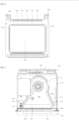
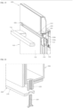
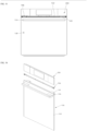
- FIG. 1 is a perspective view illustrating a cooking appliance according to the first embodiment of the present disclosure
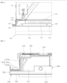
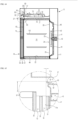
- FIG. 2 is a side cross-sectional view illustrating an internal structure of the cooking appliance as illustrated in FIG. 1
- FIG. 3 is an enlarged view of a portion of the cooking appliance as illustrated in FIG. 2
- FIG. 4 is a front view separately illustrating a front panel as illustrated in FIG. 2 .
- the cooking appliance according to the first embodiment of the present disclosure has an outer appearance defined by a main body 100.
- the main body 100 may have a substantially rectangular parallelepiped shape.
- the main body 100 may be made of a material having a predetermined strength to protect a plurality of components installed in an inner space of the main body.
- the main body 100 may include a cavity 110.
- the cavity 110 may constitute a framework of the main body 100.
- the front panel 120 may not be provided separately from the cavity 110, and a front surface of the cavity 110 may constitute the front surface of the main body 100.
- the main body 100 may be constructed such that the cavity 110 and the front panel 120 may be integrally formed with each other.
- a cooking chamber 101 may be defined in the cavity 110.
- An opening 126 may be defined in the front panel 120 so as to communicate with the cooking chamber 101.
- the cooking chamber 101 may have a hexahedral shape with an open front surface. In a state in which the cooking chamber 101 is closed, the cooking appliance may cook food by heating the inner space of the cooking chamber 101. That is, in the cooking appliance, the inner space of the cooking chamber 101 is a space in which the food is substantially cooked.
- the cooking appliance may be provided with a heating unit for heating the cooking chamber 101.
- a convection unit 160 for convection of hot air to heat the inner space of the cooking chamber 101 may be provided as the heating unit and may be disposed in rear of the cooking chamber 101.
- an upper heater 165 or an upper burner for heating the inner space of the cooking chamber 101 from an upper side thereof may be provided as a heating unit and may be disposed on top of the cooking chamber 101.
- a lower heater or a lower burner for heating the inner space of the cooking chamber 101 may be disposed under the cooking chamber 101 and may also be provided as a heating unit.
- a door 150 that selectively opens and closes the cooking chamber 101 may be pivotally provided in front of the main body 100.
- the door 150 may open and close the cooking chamber 101 in a pull-down manner in which an upper end of the door 150 pivots upwardly or downwardly about a lower end thereof.
- the door 150 may be formed in a hexahedral shape having a predetermined thickness.
- a handle 155 that may be gripped by the user when the user wants to pivot the door 150 may be installed on a front surface of the door 150.
- a see-through window may be provided in the door 150.
- the see-through window may be made of a transparent material such as glass or transparent plastic. According to the cooking appliance to which the see-through window is applied, the see-through window may need to be formed to endure high temperature and high pressure, and a function of waterproofing, heat dissipation, and the like may also be required in the see-through window.
- a control panel 200 may be provided on an upper portion of the front surface of the cooking appliance, that is, on a front surface of a portion on top of the cavity 110.
- the control panel 200 may constitute a portion of the front appearance of the cooking appliance.
- a display unit may be provided on the control panel 200.
- the display unit may include an input unit for adjusting an operation of the cooking appliance and a display for displaying an operation state of the cooking appliance.
- the input unit and the lay may be integrated into one panel.
- the input unit and the display may be integrated into the touch panel receiving a user's touch input.
- the display may display a user experience interface (UI) or a graphic user interface (GUI) related to the operation of the cooking appliance.
- UI user experience interface
- GUI graphic user interface
- the display may include at least one of a liquid crystal display (LCD), a thin film transistor-liquid crystal display (TFT-LCD), an organic light-emitting diode (OLED), a flexible display, and a three-dimensional (3D) display.
- LCD liquid crystal display
- TFT-LCD thin film transistor-liquid crystal display
- OLED organic light-emitting diode
- flexible display e.g., a flat panel display
- 3D three-dimensional
- the display When the display and a touch sensor for sensing a touch operation are stacked in a layered manner to constitute a touch screen, the display may be used as an input device as well as an output device.
- the touch sensor may be implemented as a touch film, a touch sheet, a touch pad, or the like.
- the touch sensor may be configured to convert a change in a pressure applied to a specific portion of the display or a capacitance generated at a specific portion of the display into an electric input signal.
- buttons may be displayed on the control panel 200 having such a display.
- a knock-on button for setting a function of turning on/off a lamp 70 installed in the cooking chamber 101 by the user's knock input may be displayed on the control panel 200.
- a lamp button for setting a function of manually turning on/off the lamp may be displayed on the control panel 200.
- a self-cleaning button for setting a self-cleaning function of the cooking chamber 101 may be displayed on the control panel 200.
- An electric component chamber 103 may be provided outside the cavity 110, more specifically, on top of the cavity 110.
- the electric component chamber 103 may be disposed on top of the cavity 110 and in rear of the control panel 200.
- a space for installing electric components therein may be defined inside the electric component chamber 103.
- a front surface of the electric component chamber 103 may be shielded with the front panel 120.
- the front panel 120 may be disposed between the cavity 110 and the door 150. At least a portion of the front panel 120 may be disposed to block the front surface of the electric component chamber 103.
- an upper area of the front panel 120 disposed on top of the cooking chamber 101 may shield the front surface of the electric component chamber 103.
- a portion of the front panel 120 may protrude upwardly beyond the cavity 110 to define a front boundary surface of the electric component chamber 103.
- the front panel 120 may be provided with an exhaust port 122.
- the exhaust port 122 may be formed to extend through the front panel 120 in the front-rear direction.
- the exhaust port 122 may constitute a passage defined in the front panel 120 through which air inside the electric component chamber 103 flows through the front panel 120 and is discharged to an outside out of the electric component chamber 103.
- the exhaust port 122 may be disposed at a position closer to one end of the front panel 120 in the left-right direction around a center of the front panel 120 in the left-right direction.
- the exhaust port 122 may be disposed between the center of the front panel 120 in the left-right direction and a right side of the front panel 120.
- the front panel 120 may not be provided separately from the cavity 110, and the front surface of the cavity 110 may constitute the front surface of the main body 100.
- the exhaust port 122 may be defined in a front surface of the cavity 110 formed in a shape corresponding to a shape of the front panel 120.
- the door 150 may include a door frame 151 and a front glass 153.
- the door frame 151 may constitute a framework of the door 150 and may constitute an upper surface, a lower surface, and a side surface of the door 150.
- the door frame 151 may be formed in a hexahedral shape with open front and rear surfaces.
- a hinge for pivotally coupling the door frame 151 to the main body 100 may be installed at a bottom of the door frame 151.
- Such a hinge may be installed at a lower end of the door frame 151, and the hinges may be installed at both opposing lateral sides of the door frame 151, respectively.
- the front glass 153 may be disposed in front of the door frame 151.
- the front glass 153 may be coupled to the door frame 151 while being disposed in front of the door frame 151 to constitute a front appearance of the door 150.
- the door 150 may further include a rear glass 156.
- the rear glass 156 may be coupled to the door frame 151 and may be disposed in rear of the door frame 151 and may constitute a rear appearance of the door 150.
- the door 150 may further include an inner glass 154.
- the door 150 includes a plurality of inner glass 154.
- the inner glass 154 may be disposed in rear of the front glass 153 and in front of the rear glass 156, and may be coupled to the door frame 151 while being disposed in rear of the front glass 153 and in front of the rear glass 156.
- the air inflow hole 132 may constitute a passage connecting a space between the upper surface of the cavity 110 and the blocking plate 131 to the cooling flow path 105. Due to the heated cavity 110, the heated air present between the upper surface of the cavity 110 and the blocking plate 131 may be introduced into the cooling flow path 105 through the air inflow hole 132 and then discharged to the outside out of the cooking appliance through the exhaust port 122.
- the heat in the space between the upper surface of the cavity 110 and the blocking plate 131 may be discharged to the outside through the air inflow hole 132, so that the cooling of the electric component chamber 103 may be more effectively performed.
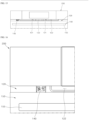
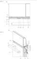
- FIG. 6 is an enlarged view of a portion of the cooking appliance as illustrated in FIG. 5
- FIG. 7 is an enlarged view of a portion of the cooking appliance as illustrated in FIG. 6 .
- the front panel 120 may be provided with a protruding surface portion 123.
- the protruding surface portions 123 may be disposed at both opposing ends of the front panel 120, respectively.
- each of the protruding surface portions 123 may protrude in a frontward direction from each lateral end portion of the front panel 120.
- each of the protruding surface portions 123 may include a first protruding surface 123a and a second protruding surface 123b.
- the first protruding surface 123a may protrude in a frontward direction from a lateral end of the front panel 120.
- the second protruding surface 123b may extend laterally from the first protruding surface 123a.
- the first protruding surface 123a may protrude in a direction perpendicular to the front panel 120, and the second protruding surface 123b may extend in a direction parallel to the front panel 120.
- the door 150 disposed in front of the front panel 120 may cover the protruding surface portion 123 and close the cooking chamber 101.
- a side surface of the door 150 may cover the first protruding surface 123 a, and a rear edge of the door 150 may cover the second protruding surface 123a and close the cooking chamber 101.
- a portion of the front glass 156 protruding further laterally beyond the remaining components of the door 150 may cover the second protruding surface 123b while being disposed in front thereof.
- a side surface of the door frame 151 may cover the first protruding surface 123a while being disposed laterally and inwardly of the protruding surface portion 123.
- a rear side of the reinforcing member 125 may be coupled to the front panel 120, and a front side of the reinforcing member 125 may be coupled to the protruding surface portion 123. More specifically, the front side of the reinforcing member 125 may be coupled to the second protruding surface 123b.
- a front surface of the reinforcing member 125 may constitute a plane parallel to the second protruding surface 123b.
- the front surface of the reinforcing member 125 may be in surface contact with the second protruding surface 123b and may be coupled to the second protruding surface 123b.
- the reinforcing member 125 coupled to the protruding surface portion 123 may firmly support the protruding surface portion 123, particularly, the second protruding surface 123b, and may reinforce the strength of the protruding surface portion 123.
- the protruding surface portion 123 may stably support the door 120 closing the cooking chamber 101 and may be in close contact with the door 120.
- the protruding surface portion 123 may further include a fastening boss 123c.
- the fastening boss 123c may protrude rearwardly from the second protrusion surface 123b.
- the second protruding surface 123b and the reinforcing member 125 may be coupled to each other by a fastening member such as a screw in a state in which the second protruding surface 123b and the reinforcing member 125 contact and face each other in the front-rear direction.
- the fastening member coupling the second protruding surface 123b and the reinforcing member 125 to each other may be stably supported on the protruding surface portion 123 by the coupling boss 123b.
- the strength of the protruding surface portion 123, particularly, the second protruding surface 123b may be more effectively strengthened.
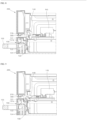
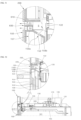
- FIGS. 8 and 9 are side cross-sectional views illustrating a structure of a door locking device of the cooking appliance as illustrated in FIG. 1 .
- a front space S may be formed in front of the electric component chamber 103.
- the front space S may be disposed in front of the front panel 120.
- the front space S may be disposed under the control panel 200.
- the front space S may be disposed on top of the door 150 that closes the cooking chamber 101.
- the front space S may be a space surrounded with the door 150, the front panel 120, and the control panel 200. That is, the front space S may be a space formed between the control panel 200 and the door 150 while being in front of the front panel 120.
- the front space S may be exposed to a position in front of the cooking appliance through a gap between the control panel 200 and the door 150.
- the exhaust port 122 may be disposed in rear of the front space S. As described above, the exhaust port 122 may be formed in the front panel 120. The air flowing in a frontward direction while cooling the electric components in the electric component chamber 103 may be discharged to the front space S through the exhaust port 122.
- the front panel 120 may be provided with a plurality of exhaust ports 122.
- the plurality of exhaust ports 122 may be arranged to be spaced apart from each other by a predetermined distance in the lateral direction.
- a partition wall 121 may be formed between the two exhaust ports 122 adjacent to each other in the lateral direction.
- the partition wall 121 may serve to improve the strength of the front panel 120 by supporting the front panel 120 while being disposed between the two adjacent exhaust ports 122.
- the door exhaust port 152 may be disposed under the front space S. As described above, the door exhaust port 152 may be formed in the upper end of the door 150. The air flowing upwardly while cooling the door 150 inside the door 150 may be discharged to the front space S through the door exhaust port 152.
- the door locking device may be provided at a front side of the main body 100.
- the door locking device may be installed on the front surface of the main body 100.
- the door locking device may include a latch 140 provided to be engaged with the door 150 and a latch driver 145 for operating the latch 140.
- the latch driver 145 and the latch 140 may be connected to each other via a link structure. While the door 150 needs to be maintained to be closed, the latch is maintained to be engaged with the door 150. When the door 150 is no greater maintained in the closed state, the state in which the latch 140 is engaged with the door 150 may be released.
- the latch 140 may be installed on the front surface of the main body 100, for example, on the front side of the cavity 110 or at the front panel 120, and may pivot in a frontward direction and protrude in the frontward direction of the main body 100.
- the latch 140 may pivot in a frontward direction and protrude in a frontward direction to be engaged with the door 150 (see FIG. 9 ), may pivot backwardly, and may be removed from the door 150 (see FIG. 8 ).
- a catching groove 151a may be defined in the upper end of the door 150.
- the catching groove 151a may be recessed downwardly in the upper end of the door frame 151.
- the latch 140 may move from a position on top of the catching groove 151a so as to be inserted into the catching groove 151a and may be engaged with the door 150, and accordingly, the door 150 may be locked by the door locking device.
- the latch 140 may be maintained in a state of being inserted into the main body 100 usually.
- the latch may protrude in a frontward direction and may lock the door 150 only during the self-cleaning process.
- the area size screened with the air guide 300 may be reduced.
- the effect of improving the aesthetics of the front surface of the cooking appliance will be reduced.
- the discharge of the air to a position in front of the cooking appliance through the front space S may be more smoothly performed.
- the air guide 300 covers a portion of each of other structures in rear of the air guide 300, and at the same time, allows a line of sight of the user that views the front gap to be concentrated on the air guide 300, thereby providing an effect that it seems like that only the air guide 300 is present in the front gap.
- the inner cover protrusion 220 is disposed at a position so as to screen the partition wall 121 distinguishing the exhaust ports 122 from each other while being positioned in front of the partition wall 121, thereby reducing the risk of thermal deformation of the inner cover protrusion 220 without interrupting the discharge of air through the exhaust port 122 and further improving the front aesthetics of the cooking appliance.
- the cover protrusions 210 and 220 may be included in the front panel 120.
- the cover protrusions 210 and 220 may be integrally formed with the control panel 120. More specifically, the cover protrusions 210 and 220 may be integrally formed with the lower end of the control panel 200.
- the air guide 300 may be made of the metal material in consideration of the fact that the air guide 300 is disposed at a path through which high-temperature air is discharged, the air guide 300 is disposed at a position on the front surface of the cooking appliance so as to be visible to the user, and the contact of the air guide 300 with the user frequently occurs.
- the cover protrusions 330 and 340 and a main body of the air guide 300a are illustrated as being made of a metal material.
- the main body of the air guide 300 and the cover protrusions 330 and 340 may be made of a metal material having excellent heat resistance and metal-specific gloss.
- cover protrusions 330 and 340 are integrally formed with the air guide 300a and are monolithic and are made of the metal material, the cover protrusions 330 and 340 may not be easily deformed even under high-temperature heat.
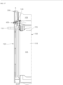
- FIG. 23 is a cross-sectional view illustrating an air flow inside the cooking appliance according to the first embodiment of the present disclosure
- FIG. 24 is an enlarged view of a portion of the cooking appliance as illustrated in FIG. 23
- FIG. 25 is an enlarged view of a portion of the cooking appliance as illustrated in FIG. 24 .
- external air may be introduced from a rear side of the cooking appliance into the electric component chamber 103 under the operation of the fan module 170. As described above, the air introduced into the electric component chamber 103 may flow in a frontward direction inside the electric component chamber 103 and may cool the electric components inside the electric component chamber 103.
- the external air may be introduced into the cooking appliance through a lower end of the main body 100.
- the external air introduced through the lower end of the main body 100 may cool various components disposed in the rear space of the cooking appliance, for example, a motor for driving the convection unit 160 while flowing through the rear space of the cooking appliance in which the convection unit 160 and the like are disposed.
- the air flowing upward while flowing through the rear space of the cooking appliance may flow toward the electric component chamber 103 through a space covered with the electric component chamber cover 135 and defined between the rear space of the cooking appliance and the electric component chamber 103.
- the air having flowed into the electric component chamber 103 may be suctioned by the fan module 170 and introduced into the cooling flow path 105.
- the air introduced into the cooling flow path 105 may flow in a frontward direction in the cooling flow path 105 and may cool the electric components in the electric component chamber 103.
- the air having flowed in a frontward direction in the electric component chamber 103 may be discharged to a position in front of the electric component chamber 103, that is, the front space S through the exhaust port 122.
- the air in the door 150 heated by the heat transferred from the cooking chamber 101 during the cooking process may be discharged to the outside out of the door 150 through the door exhaust port 152 defined in the upper end of the door 150.
- the external air in the lower end of the front portion of the cooking appliance may be introduced into the door 150 through an air flow hole defined in the lower end of the door 150 and may flow upwardly therein.
- the door 150 heated by the heat transferred from the cooking chamber 101 to the door 150 may be cooled by the air.
- the air rising in the door 150 while cooling the door 150 may be discharged to the front space S through the door exhaust port 152. That is, the air discharged through the exhaust port 122 and the air discharged through the door exhaust port 152 may merge with each other in the front space S and then may be discharged to a position in front of the cooking device.
- the front space S may be a space surrounded with the door 150, the front panel 120, and the control panel 200.
- the air guide 300 may be disposed in the front space S.
- the exhaust port 122 may communicate with the front space S while being disposed in rear of the front space S.
- the door exhaust port 152 may communicate with the front space S while being disposed under the front space S.
- the front space S may be opened toward a position in front of the cooking appliance.
- the door exhaust port 152 may be disposed between the air guide 300 and the front panel 120. Specifically, the door exhaust port 152 may be disposed in front of the exhaust port 122. That is, in the front-rear direction, the door exhaust port 152 may be disposed between the air guide 300 and the exhaust port 122.
- the door exhaust port 152 may be disposed under the air guide 300 and the exhaust port 122. In addition, the door exhaust port 152 may be defined in the upper end of the door 150, and may be defined in the second half 150b thereof.
- the door exhaust port 152 may be disposed at a position biased rearwardly in the door 150, and may be disposed at a lower vertical level than a vertical level of an uppermost end of the door 150 constituted by the front half portion 150a.
- the door exhaust port 152 is disposed at a position in the door 150 closest to the exhaust port 122 in the front-rear direction.
- the door exhaust port 152 is disposed in the front half portion 150a rather than the rear portion 150b of the door 150, the possibility that the hot air discharged through the exhaust port 122 flows back into the door 150 through the door exhaust port 152 is increased.
- the door exhaust port 152 is located at a front side in the front space S, the possibility that the air discharged through the exhaust port 122 is introduced into the door exhaust port 152 is increased.
- the hot air discharged through the exhaust port 122 flows back into the door 150 through the door exhaust port 152, cooling of the door 150 may not be smoothly performed, and the heat introduced into the front space S may not be smoothly discharged to the outside out of the cooking device.
- the door exhaust port 152 may be disposed in the rear portion 150b of the door 150, and thus, the door exhaust port 152 may be disposed at a position in the door 150 closest to the exhaust port 122 in the front-rear direction.
- the door exhaust port 152 may be disposed at a position which may be furthest from the flow area in which the air discharged through the exhaust port 122 flows, among possible positions in the front-rear direction in the door 150.
- the door exhaust port 152 may be disposed in the rear half portion 150b, and thus may be disposed at a lower vertical level than that of the uppermost end of the door 150 constituted by the front half portion 150a. That is, the door exhaust port 152 may be disposed at a position farther downwardly from the flow area in which the air discharged through the exhaust port 122 flows.
- the door exhaust port 152 may be disposed at a position which may be furthest from the flow area in which the air discharged through the exhaust port 122 flows.
- the door exhaust port 152 positioned as described above may contribute to preventing the hot air discharged into the front space S from flowing backward into the door 150.
- the door exhaust port 152 may not overlap the air guide 300 in the vertical direction, but may be disposed in rear of the air guide 300 in the front-rear direction. Accordingly, the flow of air discharged from the door exhaust port 152 may smoothly flow toward the front space S without being disturbed by the air guide 300.
- the door exhaust port 152 may be disposed between the air guide 300 and the front panel 120. That is, the air guide 300 may be disposed in front of the exhaust port 122 and the door exhaust port 152. The air guide 300 may be disposed at a position biased in a frontward direction in the front space S.
- the air guide 300 positioned as described above may guide the flow of air discharged from the exhaust port 122 and the door exhaust port 152 to the front space S toward a position in front of the front space S.
- the air discharged from the exhaust port 122 and air discharged from the door exhaust port 152 to the front space S may merge with each other in the front space S and then be discharged to a position in front of the cooking appliance.
- the air guide 300 may be disposed in a flow path (hereinafter, referred to as an "air discharge flow path") along which the air discharged from the front space S flows to a position in front of the cooking appliance.
- the air guide 300 positioned as described above may be provided in the form of a frame having a width greater than each of a length and a thickness and having a thickness smaller than each of a length and a width.
- the air guide 300 disposed at the central position of the front gap may be disposed at the center in the vertical direction of the front space S.
- the air guide 300 may be disposed in the air discharge flow path to partition the air discharge flow path into an upper portion and a lower portion. Accordingly, the air introduced into the front space S through the exhaust port 122 and the door exhaust port 152 may be divided into upper and lower portions while flowing through the air discharge flow path partitioned into the upper portion and the lower portion and the upper and lower portions of the air flow in a frontward direction in a separate manner.
- the vortex may be generated in the front space S.
- the air introduced into the front space S may not be properly discharged to the outside out of the cooking appliance, or the air in the front space S may flow back into the door 150 through the door exhaust port 152.
- the air guide 300 is disposed at the front side of the front space S, and the flow of air flowing through the air discharge flow path is divided into the upper and lower portions by the air guide 300.
- the air guide 300 disposed in the front space S and at the front side of the front space S may be disposed in the air discharge flow path to divide the flow of air flowing through the air discharge flow path into the separate upper and lower portions, thereby effectively suppressing the generation of the vortex in the front space S.
- the inner cover protrusion 220 provided to fix the air guide 300 to the control panel 200 may be disposed between the exhaust port 122 and the exhaust port 122.
- the inner cover protrusion 220 positioned as described above may screen the partition wall 121 while being disposed in front of the partition wall 121.
- the inner cover protrusion 220 may be disposed at a position at which the inner cover protrusion 220 does not overlap the exhaust port 122 in the front-rear direction, thereby effectively lowering a flow path resistance caused by the cover protrusions 210 and 220 or the air guide 300.
- a front end 301 of the air guide 300 disposed in the front space S and at the front side of the front space S may be disposed at a position vertically overlapping at least a portion of the front glass 153 of the door 150.
- the front end 301 of the air guide 300 may coincide with a rear end of the front glass 152 in the front-rear direction, or may be disposed at a position positioned in a frontward direction beyond the rear end of the front glass 152.
- the air guide 300 is disposed at a position biased in a frontward direction in the front space S, the flow of air flowing from the front space S toward a position in front of the cooking appliance may be more effectively guided by the air guide 300.
- the air guide 300 is disposed at a position where the air guide 300 is visible to the outside out of the cooking appliance as described above, an esthetic sense resulting from the air guide 300 may be more effectively expressed.
- the condensed water deposited on the lower end of the control panel 200 falls down onto the upper end of the door 150, the water may collide with the door 150 and may bounce therefrom toward the surroundings around the door 150 to contaminate the surroundings.
- the air guide 300 When, as described above, the air guide 300 is disposed at a position biased in a frontward direction in the front space S, the air guide may block the space between the control panel 200 and the door 150 so that the condensate or the condensed water deposited on the lower end of the control panel 200 does not fall onto the door 150.
- the air guide 300 having the above-described configuration, the occurrence of the contamination of the cooking appliance due to the condensed water may be significantly reduced.
- the rear end 303 of the air guide 300 may be disposed in front of the door exhaust port 152 in the front-rear direction.
- a passage having a sufficient height for discharging the air inside the door 150 to the front space S through the door exhaust port 152 may be formed between the door exhaust port 152 and the air guide 300.
- the first flow path S1 may be formed between the door 150 and the first guide portion 400a
- the second flow path S2 may be formed between the first guide portion 400a and the second guide portion 400b
- the third flow path S3 may be formed between the second guide portion 400b and the control panel 200.
- the air guide 400 may be disposed under the control panel 200 so as to be coupled to the control panel 200.
- the air guide 400 may be coupled to the plurality of cover protrusions 210 and 220 spaced apart from each other in the lateral direction and thus may be stably fixed to the lower end of the control panel 200 via the plurality of cover protrusions 210 and 220.
- the connector 400c may be formed in a form of a protrusion which vertically extends so as to connect the first guide portion 400a and the second guide portion 400b to each other and is exposed to a position on top of the second guide portion 400b.
- the connector 400c may be exposed to a position on top of the second guide portion 400b so as to face the cover protrusion 210 and 220, and may be coupled to one of the cover protrusions 210 and 220.
- the plurality of cover protrusions 210 and 220 may be laterally arranged and may be disposed on the lower end of the control panel 200.
- the air guide 400 may include a plurality of connectors 400c arranged along the lateral direction.
- the plurality of cover protrusions 210 and 220 may be disposed on the control panel 200 so as to be spaced apart from each other by a predetermined distance in the lateral direction.
- the number of connectors 400c corresponding to the number of cover protrusions 210 and 220 may be disposed in the air guide 400 and may be arranged to be spaced apart from each other in a lateral direction by a spacing corresponding to the spacing between adjacent ones of the cover protrusions 210 and 220.
- the connectors 400c disposed as described above may be connected to the cover protrusions 210 and 220 in the vertical direction, respectively.
- the air guide 400 may be coupled to the control panel 200.
- Each of the guide portions 400a and 400b may include a guide main body 310 and an extension 320, as shown in FIGS. 30 and 31 .
- the air guide 400 of the present embodiment provided as described above may be disposed in the gap between the control panel 200 and the door 150, that is, in the front gap.
- the air guide 400 which is disposed as described above may screen a portion of each of the front panel 120, the latch 140, the electronic components, and the like while being disposed in front thereof.
- the air guide 400 may screen a portion of the front gap between the control panel 200 and the door 150, and accordingly, a portion of each of the front panel 120, the latch 140, and the electronic components which is otherwise exposed to a position in front of the cooking appliance through the front gap may be screened with the air guide 400.
- the air guide 400 of the present embodiment may include the plurality of guide portions 400a and 400b.
- the air guide 400 may include the plurality of guide portions 400a and 400b.
- the area size screened with the air guide 400 is increased, thereby effectively improving the front appearance of the cooking appliance, while suppressing the decrease in the air discharge efficiency through the front gap.
- the air guide 400 may be coupled to the control panel 200 via the cover protrusions 210 and 220.
- the air guide 400 may be provided with the connector 400c connected to the cover protrusions 210 and 220.
- the connector 400c may be connected to the cover protrusions 210 and 220 in the vertical direction so as to couple the air guide 400 to the control panel 200.
- FIG. 32 is a front view illustrating a portion of a front surface of the cooking appliance according to the second embodiment of the present disclosure
- FIG. 33 is an enlarged view of a portion of a front surface of the cooking appliance as illustrated in FIG. 32 .
- each of the connectors 400c respectively connected to the cover protrusions 210 and 220, particularly, the inner cover protrusions 220 may be disposed at a position at which the inner cover protrusions 220 screens the partition wall 121 while being disposed in front thereof, as shown in FIGS. 32 and 33 . That is, each connector 400c constructed to be connected to the inner cover protrusion 220 may screen the partition 121 while being disposed in front thereof as the inner cover protrusion 220 may.
- the connector 400c disposed as described above not only provides a function of connecting the plurality of guide portions 400a and 400b to each other, and a function of coupling the air guide 400 to the control panel 200, but also provides an effect of lowering the risk of heat deformation of the air guide 400 without interrupting the discharge of air through the exhaust port 122 and an effect of improving the front appearance of the cooking appliance.
- the partition wall 121 when the partition wall 121 is screened with the inner cover protrusion 220 and the connector 400c connected to each other in the vertical direction as described above, the areas size screened with the partition wall 121 may be expanded, thereby more effectively improving the esthetic appearance of the front surface of the cooking appliance.
- FIG. 34 is a cross-sectional perspective view illustrating a coupling structure between the air guide and the control panel
- FIG. 35 is a cross-sectional exploded perspective view illustrating a removed state of the air guide and the control panel as shown in FIG. 34 from each other.
- the cover protrusions 210 and 220 may be included in the control panel 200.
- the cover protrusions 210 and 220 may be integrally formed with the control panel 200. More specifically, the cover protrusions 210 and 220 may be integrally formed with the lower end of the control panel 200.
- the lower end of the control panel 200 and the cover protrusions 210 and 220 are made of a plastic material. Since the cover protrusions 210 and 220 are integrally formed with the lower end of the control panel 200 and are made of the plastic material, a cost required for the addition of the cover protrusions 210 and 220 may be reduced, and the weight of the cover protrusions 210 and 220 may be considerably lowered than that in a case when the cover protrusions 210 and 220 are made of a metal material.
- the air guide 400 may be made of a metal material.
- the air guide 400 may be made of a metal material having excellent heat resistance and metal-specific gloss.
- the air guide 400 may not be easily deformed even under high-temperature heat, may not be easily damaged even when impact is applied thereto, and may contribute to improving the aesthetics of the cooking appliance due to the metal gloss.
- the air guide 400 may be made of the metal material in consideration of the facts that the air guide 400 is disposed in a path through which high-temperature air is discharged, the air guide 400 is disposed at a position at which the air guide is visible to the user in front of the cooking appliance, and the contact of the air guide with the user frequently occurs.
- the cover protrusions 210 and 220 may be coupled to the connector 400c.
- a hollow may be formed in each of the cover protrusions 210 and 220, and a fastening hole communicating with the hollow may be formed to vertically extend through the connector 400c.
- Each of the cover protrusions 210 and 220 and the connector 400c may be coupled to each other via a fastening member 201 such as a screw.
- FIG. 36 is a cross-sectional view illustrating an air flow inside the cooking appliance according to the second embodiment of the present disclosure
- FIG. 37 is an enlarged view of a portion of the cooking appliance as illustrated in FIG. 36
- FIG. 38 is an enlarged view of a portion of the cooking appliance as illustrated in FIG. 37 .
- the air guide 400 may guide the flow of air discharged from the exhaust port 122 and the door exhaust port 152 into the front space S to the front side of the front space S.
- the air discharged from the exhaust port 122 and the air discharged from the door exhaust port 152 to the front space S may merge with each other in the front space S and be discharged to a position in front of the cooking appliance.
- the air guide 400 may be disposed in a flow path through which the air is discharged from the front space S to a position in front of the cooking appliance, that is, the air discharge flow path.
- the air guide 400 disposed as described above may include the first guide portion 400a and the second guide portion 400b.
- Each of the guide portions 400a and 400b may be provided in a form of a frame having a width greater than each of a length and a thickness and smaller than each of a length and a width.
- the air guide 400 including the first guide portion 400a and the second guide portion 400b may be disposed in the air discharge flow path so as to divide the air discharge flow path into a plurality of flow paths.
- the air discharge flow path is divided into the three flow paths S 1, S2, and S3.
- the air discharge flow path may be divided into the first flow path S1 formed between the door 150 and the first guide portion 400a, the second flow path S2 formed between the first guide portion 400a and the second guide portion 400b, and the third flow path S3 formed between the second guide portion 400b and the control panel 200.
- the air introduced into the front space S through the exhaust port 122 and the door exhaust port 152 may be divided into separate upper, middle, and lower portions through the flow paths S 1, S2, and S3 divided as described above, and then, the separate upper, middle, and lower portions may flow in the frontward direction in the separate manner.
- first discharged air The air (hereinafter, referred to as "first discharged air") discharged through the door exhaust port 152 may mainly flow through the first flow path S1 disposed at the lowermost level among the flow paths S1, S2, and S3.
- second discharged air discharged through the exhaust port 122 may mainly flow through the third flow path S3 disposed at the uppermost level among the flow paths S 1, S2, and S3.
- the mixed air in which the first discharged air and the second discharged air are mixed with each other may flow through the second flow path S2 disposed between the first flow path S 1 and the third flow path S3.
- Each of the first discharged air and the second discharged air is high-temperature air. Accordingly, each of the first discharged air and the second discharged air may flow upwardly while flowing through the front space S.
- the first discharged air discharged upwardly from the door exhaust port 152 further induces the upward flow of the air flowing through the front space S. Accordingly, an amount of the high-temperature air flowing through the front space S and contacting the control panel 200 may be further increased.
- the air guide 400 is disposed in the front space S formed between the door 150 and the control panel 200.
- only a portion of the flow of air flowing through the front space S may flow in a frontward direction through the third flow path S3. Since the control panel 200 is disposed on top of the third flow path S3, only the air flowing through the third flow path S3 may be in contact with the control panel 200. It may be difficult for the air flowing through the first flow path S 1 or the air flowing through the second flow path S2 to contact the control panel 200.
- the air guide 400 of the present embodiment may divide the flow of air flowing through the front space S into a plurality of the portions of the air flow arranged in the vertical direction, thereby reducing the amount of the air flowing through the front space S so as to contact the control panel 200.
- the air guide 400 as described above may block the upward flow of the first discharged air by blocking the space between the door 150 and the control panel 200.
- the condensed water may be deposited on the lower end of the control panel 200.
- the air guide 400 When, as described above, the air guide 400 is disposed at a position biased in a frontward direction in the front space S, the air guide may block the space between the control panel 200 and the door 150 so that the condensate deposited on the lower end of the control panel 200 does not fall onto the door 150.
- the air guide 400 having the above-described configuration, the occurrence of contamination of the structures of the cooking appliance due to the condensed water may be significantly reduced.
- the humidity and temperature of the first discharged air may be different from the humidity and temperature of the second discharged air.
- the vortex may be generated in the front space S.
- the air introduced into the front space S may not be properly discharged to the outside out of the cooking appliance, or the air in the front space S may flow back into the door 150 through the door exhaust port 152.
- the air guide 400 may be disposed at a position biased in the frontward direction in the front space S, and the air guide 400 may serve to prevent the first discharged air and the second discharged air from being excessively mixed with each other in the front space S.
- the first discharged air may mainly flow in a frontward direction through the first flow path S 1
- the second discharged air may mainly flow in a frontward direction through the third flow path S3.
- the mixed air in which a portion of an upper portion of the first discharged air and a portion of a lower portion of the second discharged air are mixed with each other may flow in a frontward direction through the second flow path S2.
- the air guide 400 may allow the first discharged air and the second discharged air in a frontward direction through the first flow path S 1 and the third flow path S3, respectively in a state in which a substantial portion of the first discharged air and a substantial portion of the second discharged air are not mixed with each other, thereby preventing the first discharged air and the second discharged air from being excessively mixed with each other in the front space S.
- the air guide 400 may effectively suppress the generation of the vortex in the front space S, and thus may effectively suppress degradation of air discharge performance due to the vortex and occurrence of the air backflow into the inside of the door 150 due to the vortex.
- the inner cover protrusion 220 and the connector 400c provided to fix the air guide 400 to the control panel 200 may be disposed between the exhaust ports 122 adjacent to each other in the lateral direction.
- the inner cover protrusion 220 and the connector 400c disposed as described above may screen the partition wall 121 while being disposed in front of the partition wall 121, and may be disposed at a position at which the inner cover protrusion 220 and the connector 400c do not overlap the exhaust port 122 in the font-rear direction, thereby effectively lowering a flow path resistance generated by the inner cover protrusions 220 or the connector 400c.
- the front end 401 of the air guide 400 disposed at the front side of the front space S and in the front space S may be disposed at a position vertically overlapping at least a portion of the front glass 153 of the door 150.
- the front end 401 of the air guide 400 may coincide with the rear end of the front glass 152 in the front-rear direction, or may be disposed at a position biased in a frontward direction from the rear end of the front glass 152.
- the air guide 400 is disposed at a position biased in a frontward direction in the front space S, flow of air flowing from the front space S toward a position in front of the cooking appliance may be more effectively guided by the air guide 400.
- the air guide 400 is disposed at a position where the air guide 400 is well visible to the user in front of the cooking appliance as described above, the esthetic sense resulting from the air guide 400 may be more effectively expressed.
- FIG. 39 is an enlarged view of a portion of a cooking appliance having an air guide according to a third embodiment of the present disclosure
- FIG. 40 is an enlarged view of a portion of the cooking appliance as shown in FIG. 39 .
- a first guide portion 500a and a second guide portion 500b may extend in a non-parallel manner to each other, as illustrated in FIGS. 39 and 40 .
- Each of the first guide portion 500a and the second guide portion 500b may constitute a partition surface extending across the front space in the horizontal direction.
- an upper surface and a lower surface of each of the first guide portion 500a and the second guide portion 500b may constitute the partition surface, and each partition surface may be formed as a flat surface.
- the partition surface of the first guide portion 500a and the partition surface of the second guide portion 500b may extend in a non-parallel manner to each other.
- a vertical distance between a front end of the first guide portion 500a and a front end of the second guide portion 500b is greater than a vertical distance between a rear end of the first guide portion 500a and a rear end of the second guide portion 500b.
- the air flowing through the air guide 500 may be spread across a wide range along the vertical direction and may be discharged in the frontward direction, thereby further improving the air discharge efficiency through the front gap of the cooking appliance.
- each of an air inlet of the first flow path S 1 and an air inlet of the third flow path S3 may be larger than an air inlet of the second flow path S2.
- the probability at which the first discharged air and the second discharged air are mainly discharged through the first flow path S 1 and the third flow path S3, respectively is higher than the probability at which the first discharged air and the second discharged air are mainly discharged through the second flow path S2, such that excessive mixing between the first discharged air and the second discharged air in the front space S may be more effectively suppressed.
- FIG. 41 is an enlarged view of a portion of a cooking appliance according to a fourth embodiment of the present disclosure
- FIG. 42 is a front view illustrating a cooking appliance according to the fourth embodiment of the present disclosure
- FIG. 43 is a rear exploded perspective view illustrating an exploded state of the door, the control panel, and the air guide as shown in FIG. 42
- FIG. 44 is an enlarged view of a portion of the door and the air guide as shown in FIG. 43 .
- an air guide 600 may be disposed between the door 150 and the control panel 200, like the air guides illustrated in the above-described embodiments.
- the air guide 600 may divide the space between the door 150 and the control panel 200 into upper and lower portions/
- the air guide 600 may be disposed in the front space S, and may divide at least a portion of the front space S into the first space S1 and the second space S2.
- a lateral dimension, i.e. a width, of the air guide 600 may correspond to a lateral dimension of the front space S.
- the width of the air guide 600 may correspond to at least one of a lateral dimension of the control panel 200 and a lateral dimension of the door 150.
- the first space S1 may be a space between the control panel 200 and the air guide 600
- the second space S2 may be defined as a space between the air guide 600 and the door 150.
- first space S1 may be a space between a guide main body 610 which will be described later and the control panel 200
- second space S2 may be defined as a space between the guide main body 610 which will be described later and the door 150.
- the first space S1 and the second space S2 may be vertically isolated from each other via the guide main body 610.
- the air guide 600 may be disposed in the front space S, and may be disposed at a position biased in a frontward direction in the front space S.
- the air guide 600 may divide a front area of the front space S into the first space S1 and the second space S2.
- the air guide 600 may include the guide main body 610.
- the guide main body 610 may occupy a significant portion of the air guide 600, and may constitute a significant portion of the appearance of the air guide 600.
- the guide main body 610 may be disposed between the control panel 200 and the door 150 so as to vertically partition a space between the control panel 200 and the door 150.
- the guide main body 610 may partition the space between the control panel 200 and the door 150 into the first space S1 and the second space S2.
- the guide main body 610 may be formed in a planar shape parallel to the bottom surface of the control panel 200 or the top surface of the door 150.
- the guide main body 610 may be formed in a shape including a plane perpendicular to the vertical axis.
- the air guide 600 may further include an extension 615.
- the extension 615 may be disposed on each of both opposing lateral sides of the guide main body 610.
- the extension 615 may protrude from the guide main body 610 in a lateral direction.
- the extension 615 is not a part involved in a coupling between the air guide 600 and the main body 100, but is not a part involved in inducing the air discharge flow.
- a length of the extension 615 may be set to be smaller than a length of the guide main body 610.
- the extension 615 is formed in a shape in which the length of the extension 615 is smaller than the length of the guide main body 610, the overall size and weight of the air guide 600 may not unnecessarily increase.
- the extension 615 may be disposed in a position biased in a frontward direction in the air guide 600. Further, the guide main body 610 and the extension 615 may be laterally connected to each other so that a front end of the extension 615 and a front end of the guide main body 610 are aligned with each other in the same line.
- the outer appearance of the air guide 600 visible to the user in front of the cooking appliance may be continuous and smooth.
- the extension 615 may be disposed in front of the protruding surface portion 123 (see FIG. 4 ). As described above, the protruding surface portion 123 is formed to protrude in a frontward direction from the lateral end of the front panel 120.
- the extension 615 disposed in front of the protruding surface portion 123 may be formed to have the length smaller than that of the guide main body 610 and may be disposed in a position biased in a frontward direction in the air guide 600, thereby avoiding interference with the protruding surface portion 123.
- the extension 615 formed in the shape as described above may provide an effect of maintaining the aesthetics of the air guide 600 visible to a position in front of the cooking appliance, and an effect of not unnecessarily increasing the size and weight of the air guide 600 while avoiding interference with the protruding surface portion 123.
- FIG. 45 is a side cross-sectional view illustrating an internal structure of a door and an air guide of a cooking appliance according to the fourth embodiment of the present disclosure
- FIG. 46 is a cross-sectional perspective view illustrating a connection structure between an air guide and a door.
- the air guide 600 may be disposed between the door 150 and the control panel 200 and may be installed on the door 150.
- the air guide 600 may be installed on the top cover 157 constituting an upper end of the door 150.
- the air guide 600 is illustrated as being integrally formed with the door 150.
- the air guide 600 may be installed on the door 150 so as to be coupled to the top cover 157.
- the air guide 600 may further include a connection protrusion 620.
- the connection protrusion 620 may protrude upwardly from the door 150 toward the guide main body of the air guide 600.
- connection protrusion 620 may be disposed between the top cover 157 and the guide main body 610.
- the connection protrusion 620 may connect the top cover 157 and the guide main body 620 to each other such that the top cover 157 and the guide main body 620 are spaced from each other at a predetermined spacing in the vertical direction. That is, the connection protrusion 620 may connect the door 150 and the air guide 600 to each other so as to space the door 150 from the air guide 600 by a predetermined distance in the vertical direction.
- a plurality of connection protrusions 620 may be disposed between the door 150 and the air guide 600, more specifically, between the top cover 157 and the guide main body 610.
- the plurality of connection protrusions 620 may be arranged to be spaced apart from each other by a predetermined distance in the lateral direction.
- the guide main body 610 may be spaced, by a predetermined distance, upwardly from the door 150.
- a passage for opening the front space S toward a position in front of the cooking appliance may be formed between adjacent ones of the plurality of connection protrusions 620.
- the air guide 600 may be integrally formed with the top cover 157.
- the top cover 157, the connection protrusion 620, and the guide main body 610 may be integrally formed with each other.
- the extensions 615 respectively disposed on both opposing sides of the guide main body 610 may be integrally formed with the top cover 157, the connection protrusion 620, and the guide main body 610.
- the top cover 157 and the air guide 600 including the connection protrusion 620 may be made of a plastic material.
- the top cover 157 together with the air guide 600 including the connection protrusion 620 may be injection-molded such that the top cover 157 may be integrally formed with the air guide 600.
- the manufacturing of the top cover 157, the manufacturing of the air guide 600, and the coupling work of the top cover 157 and the air guide 600 to each other may be completed by one molding work, such that a cost and time required for manufacturing and installing the air guide 600 may be reduced.
- the air guide 600 may be made of a metal material.
- the air guide 600 may be made of a metal material having excellent heat resistance and metal-specific gloss. The air guide 600 may not be easily deformed even under high-temperature heat, may not be easily damaged even when impact is applied thereto, and may contribute to improving the aesthetics of the cooking appliance due to the metal gloss.
- the top cover 157 and the air guide 600 may be made of a metal material together.
- the top cover 157 may be made of a plastic material, and only the air guide 600 may be made of a metal material.
- top cover 157 and the air guide 600 are made of the metal material together, the top cover 157 and the air guide 600 may be integrally cast with each other.
- the top cover 157 is made of a plastic material and only the air guide 600 is made of a metal material
- the top cover 157 and the air guide 600 may be manufactured in an insert injection molding manner such that only a lower end of the connection protrusion 620 is inserted into the top cover 157.
- the top cover 157 may be detachably coupled to the door 150. That is, the top cover 157 and the air guide 600 of the present embodiment may be removed from the door 150 as necessary, and may be recombined with the door 150.
- the top cover 157 and the air guide 600 may be easily cleaned or repaired in a state of being removed from the door 150, and may be easily and quickly replaced upon aging or damage.
- the air guide 600 integrally formed with the top cover 157 may move together with movement of the door 150. For example, when the door 150 pivots in a frontward direction to open the cooking chamber 101, the air guide 600 may move in a frontward direction under the movement of the door 150.
- the air guide 600 When the air guide 600 is installed on the control panel 200, the air guide 600 may be disposed at a position at which the exhaust port 122 is screened with the air guide while being disposed in front of the exhaust port 122.
- the air guide 600 disposed at this position may be an obstacle that prevents the user from accessing the exhaust port 122 from a position in front of the cooking appliance.
- the air guide 600 fixed to the lower end of the control panel 200 may become an obstacle which prevents the user from accessing the exhaust port 122.
- the air guide 600 is installed on the door 150 as illustrated in the present embodiment. In this case, when the door 150 pivots in a frontward direction for the user to clean the exhaust port 122 and the surroundings around the exhaust port 122, the air guide 600 also moves together with the movement of the door 150.
- the front side of the exhaust port 122 blocked with the air guide 600 is entirely opened, and the user may easily access the exhaust port 122 and the surroundings around the exhaust port 122.
- the air guide 600 is installed on the door 150 instead of being installed on the lower end of the control panel 200, the exhaust port 122 and the surroundings around the exhaust port 122 may be effectively cleaned.
- FIG. 47 is a front view illustrating a portion of a front surface of the cooking appliance according to an embodiment.
- the air guide 600 may be connected to the door 150 via the connection protrusion 620 and may be supported by the door 150.
- connection protrusion 620 may space the guide main body 610 upwardly from the door 150 and support the guide main body 610. Further, the air guide 600 supported on the connection protrusion 620 may be disposed at the central position.
- At least one of the plurality of connection protrusions 620 may be disposed at a position at which the at least one connection protrusion 620 screens at least a portion of the latch 140 while being disposed in front thereof. At least a portion of the latch 140 is screened with the connection protrusion 620 disposed as described above. Accordingly, in the front view, at least a portion of the latch 140 is screened with the connection protrusion 620 and is not visible.
- connection protrusion 620 may protrude from the upper end of the door 150 to the central position.
- the connection protrusion 620 may screen the lower half portion of the latch 140 exposed through the front gap while being disposed in front thereof.
- a vertical level of the upper half portion of the latch 140 may be higher than a vertical level of the air guide 600 and thus the upper half portion of the latch 140 may not be screened with the air guide.
- connection protrusion 620 may protrude from the door 150 by a length required to connect the air guide 600 with the door 150 to each other, and may protrude from the control panel 200 by a length required to screen the lower half portion of the latch 140.
- connection protrusion 620 may protrude by only a predetermined length so as to fix the air guide 600 so that the air guide is positioned at the center position and at the same time so as to screen the lower half portion of the latch 140, and may not protrude by a length greater than the predetermined length.
- connection protrusion 620 may screen a portion of the latch 140 which may affect the front aesthetics of the cooking appliance, and may allow the air guide 600 to be disposed at the center position, thereby contributing to effectively improving the front aesthetics of the cooking appliance.
- the air guide 600 may be disposed in the front gap, and may be disposed at a position biased in a downward direction from a vertical center of the front gap.
- the air guide 600 should be disposed at the above-defined position so that the user may better identify the air guide 300.
- the aesthetic sense of the home appliance resulting from the air guide 600 may be more effectively expressed.
- the air guide 600 may be disposed at a position biased downwardly from the vertical center of the front gap, such that the aesthetic sense may be effectively expressed.
- connection protrusion 620 may be shortened correspondingly.
- connection protrusion 620 When, as described above, the vertical dimension of the connection protrusion 620 is shortened, the supporting of the air guide 600 by the connection protrusion 620 may be more stable.
- At least one of the plurality of connection protrusions 620 may be disposed at a position at which the at least one of the plurality of connection protrusions 620 screens at least a portion of the partition wall 121 while being disposed in front thereof. At least a portion of the partition wall 121 is screened with the connection protrusion 620 disposed as described above. Accordingly, in the front view of the cooking appliance, at least a portion of the partition wall 121 is not screened with the connection protrusion 620.
- connection protrusion 620 is disposed at a position at which the connection protrusion 620 screens the partition 121 while being disposed in front thereof, so that the number of vertical structures exposed through the front gap to the outside is not increased, and the connection protrusion 620 is disposed at a position so as to non-overlap the exhaust port 122 in the front-rear direction.
- FIG. 48 is a cross-sectional view illustrating an air flow inside the cooking appliance according to the fourth embodiment of the present disclosure
- FIG. 49 is an enlarged view of a portion of the cooking appliance as illustrated in FIG. 48
- FIG. 50 is an enlarged view of a portion of the cooking appliance as illustrated in FIG. 49
- FIG. 51 is an enlarged view of a portion of the cooking appliance as illustrated in FIG. 50 .
- the air guide 600 may be disposed between the control panel 200 and the door 150, and may divide the space between the control panel 200 and the door 150 into the first space S1 and the second space S2.
- each of the air introduced into the front space S through the exhaust port 122 and the air introduced into the front space S through the door exhaust port 152 may be divided into upper and lower portions through the air discharge flow path partitioned into the first space S1 and the second space S and then the upper and lower portions may flow in the frontward direction in a separate manner.
- first discharged air The air introduced into the front space S through the exhaust port 122 (hereinafter, referred to as "first discharged air”) is discharged in a high-temperature state, and thus flows upwardly while flowing through the front space S. Accordingly, the main flow of the first discharged air may be guided toward the first space S1.
- first discharged air may flow toward the first space S1 or be mixed with air introduced into the front space S through the door exhaust port 152, the main flow of the first discharged air may be directed toward the first space S1.
- the door exhaust port 152 may be disposed at a lower vertical level than that of the air guide 600. Accordingly, the main flow of the air (hereinafter, referred to as "second discharged air") introduced into the front space S through the door exhaust port 152 may be guided toward the second space S2 formed under the guide main body 610.
- second discharged air the main flow of the air
- the main flow of the second discharged air may be directed toward the second space S2.
- the vortex may be generated in the front space S.
- the air introduced into the front space S may not be properly discharged to the outside out of the cooking appliance, or the air in the front space S may flow back into the door 150 through the door exhaust port 152.
- the air guide 600 is disposed at the front side of the front space S in the front space S, and the flow of air flowing through the air discharge flow path is divided into the upper and lower portions via the air guide 600.
- the air guide 600 disposed at the front side of the front space S in the front space S may be disposed in the air discharge flow path so as to divide the flow of air flowing through the air discharge flow path into the isolated upper and lower portions, thereby effectively suppressing the generation of the vortex in the front space S.
- the temperature of the first discharged air discharged from the electric component chamber 103 may be higher than the temperature of the second discharged air discharged from the door 150.
- the air guide 600 of the present embodiment may guide the flow of air so that the first discharged air flows through the first space S1.
- the air guide 600 may guide the flow of air so that the first discharged air relatively hotter than the second discharged air flows through the first space S1 as a space positioned at a position biased upwardly in the front space.
- the air guide 600 may guide an air discharge flow so that a distance between the flow of the first discharged air and the door 150 increases.
- the air is discharged from a position far away from the door 150 in the front space S toward a position in front of the cooking appliance, such that a distance between the hot air discharged to a position in front of the cooking appliance and the door 150 is increased correspondingly.
- FIG. 52 is an enlarged view of a portion of a cooking appliance according to a fifth embodiment of the present disclosure
- FIG. 53 is a front view illustrating a cooking appliance according to the fifth embodiment of the present disclosure
- FIG. 54 is a front exploded perspective view illustrating an exploded state of the door, the control panel, and the air guide as shown in FIG. 53
- FIG. 55 is a rear exploded perspective view illustrating an exploded state of the door, the control panel, and the air guide as shown in FIG. 53
- FIG. 56 is a front perspective view separately illustrating the air guide according to the fifth embodiment of the present disclosure
- FIG. 57 is a rear perspective view of the air guide as shown in FIG. 56 .
- an air guide 700 may be disposed between the door 150 and the control panel 200, like the air guides illustrated in the above-described embodiments.
- the air guide 700 may partition the space between the door 150 and the control panel 200 into upper and lower spaces.
- the air guide 700 may be disposed in the front space S, and may partition at least a portion of the front space S into the first space S1 and the second space S2.
- the air guide 700 may include a guide main body 710.
- the guide main body 710 may occupy a significant portion of an area of the air guide 700, and may constitute a significant portion of the appearance of the air guide 700.
- the guide main body 710 may be disposed between the control panel 200 and the door 150 to vertically partition a space between the control panel 200 and the door 150.
- the guide main body 710 may divide the space between the control panel 200 and the door 150 into the first space S1 and the second space S2.
- the guide main body 710 may be formed in a planar shape parallel to the bottom surface of the control panel 200 or the top surface of the door 150.
- the guide main body 710 may be formed in a shape including a plane perpendicular to the vertical axis.
- the air guide 700 may further include an extension 715.
- the extension 715 may be disposed at each of both opposing lateral sides of the guide main body 710.
- the extension 715 may protrude from the guide main body 710 in a lateral direction.
- a length of the extension 715 may be set to be smaller than a length of the guide main body 710. Since the extension 715 is formed in a form in which the length of the extension 715 is smaller than the length of the guide main body 710, the overall size and weight of the air guide 700 may not unnecessarily increase.
- the extension 715 may be disposed in a position biased in a frontward direction in the air guide 700. Further, the guide main body 710 and the extension 715 may be laterally connected to each other so that a front end of the extension 715 and a front end of the guide main body 710 are aligned with each other in the same line.
- extension 715 protrudes from the guide main body 710 such that a front end of the extension 715 and a front end of the guide main body 710 are aligned with each other in the same line.
- the outer appearance of the air guide 700 visible to a position in front of the cooking appliance may be continuous and smooth.
- FIG. 58 is an enlarged view illustrating a coupling portion between the air guide and the front panel
- FIG. 59 is a cross-sectional perspective view illustrating a coupling structure between the air guide and the front panel.
- the air guide 700 may further include a coupling portion 720.
- the air guide 700 may be coupled to the front surface of the main body 100, more specifically, the front panel 120.
- the coupling portion 720 may be provided for coupling the front panel 120 and the air guide 700 to each other.
- the coupling portions 720 may be disposed on both opposing lateral sides of the guide main body 710, respectively.
- the guide main body 710 may constitute a middle portion of the air guide 700, and the coupling portion 720 may constitute each of both opposing lateral ends of the air guide 700.
- each of the coupling portions 720 and the guide main body 710 may be connected to each other via the extension 715.
- a significant portion of the guide main body 710 may be disposed in front of the exhaust port 122.
- each of the coupling portions 720 may be disposed in front of the protruding surface portion 123.
- a significant portion of the extension 715 may be disposed in front of the front panel 120, and may be disposed in an area between the exhaust port 122 and the protruding surface portion 123.
- the front panel 120 may include a panel main body 125 and the protruding surface portion 123.
- the panel main body 125 may be disposed in front of the cavity 111 and may constitute a significant portion of the appearance of the front panel 120.
- the exhaust port 122 and the opening 126 may be formed in the panel main body 125.
- the protruding surface portions 123 may constitute both opposing ends of the front panel 120, respectively. Each of the protruding surface portions 123 may protrude in a frontward direction from the panel main body 125.
- the panel main body 125 may constitute a vertical plane.
- the protruding surface portion 123 may constitute a plane parallel to the panel main body 125, and may constitute a plane disposed in front of the panel main body 125.
- a pair of protruding surface portions 123 may be respectively disposed on both lateral sides of the panel main body 125.
- the exhaust port 122 may be formed in the panel main body 125, and the pair of protruding surface portions 123 may be spaced apart from each other in a lateral direction while the exhaust ports 122 are interposed therebetween.
- the air guide 700 may be coupled to the front panel 120 in an area between a lateral end of the front panel 120 and the exhaust port 122. That is, the coupling between the coupling portion 720 and the front panel 120 may be present in the area between the lateral end of the front panel 120 and the exhaust port 122.
- the pair of coupling portions 720 may be spaced apart from each other by a spacing corresponding to a spacing between the pair of protruding surface portions 123.
- Each of the coupling portions 720 disposed as described above may be disposed in front of the protruding surface portion 123 and coupled to each of the protruding surface portions 123.
- the pair of coupling portions 720 may be spaced apart from each other in the lateral direction while the exhaust ports 122 formed in the panel main body 125 are disposed therebetween.
- the pair of coupling portions 720 may be coupled to the protruding surface portions 123 while being disposed in front of the protruding surface portion 123, respectively.
- Each coupling portion 720 may be formed to protrude laterally from the lateral end of the extension 715.
- each coupling portion 720 may be formed in a hollow cylindrical shape.
- the coupling portion 720 may be disposed to face and contact the front panel 120, more specifically, the protruding surface portion 123 in the front-rear direction.
- the hollow formed in the coupling portion 720 may open an inside of the coupling portion 720 in the front-rear direction.
- the front panel 120 and the air guide 700 may be coupled to each other.
- the coupling between the protruding surface portion 123 and the coupling portion 720 may be achieved via a fastening member 705 such as a screw passing through the front panel 120 and the coupling portion 720.
- a fastening work of the front panel 120 and the coupling portion 720 using the fastening member 705 may be performed in a state in which a front surface of the main body 100 is opened. Since a fastened portion of the coupling portion 720 is exposed in the frontward direction, a worker may perform the fastening work while viewing the coupling portion 720 while being positioned in front thereof.
- the air guide 700 is constructed to allow the worker to install the air guide 700 onto the cooking appliance while viewing the air guide 700 while being positioned in front thereof, such that the installation and disassembly of the air guide 700 may be very easily performed.
- the air guide 700 may be constructed such that the worker may easily and quickly assemble the air guide 700 with the cooking appliance, and also may easily and quickly perform maintenance and repair of the air guide 700.
- the coupling between the air guide 700 and the front panel 120 may be achieved in an area adjacent to the lateral end of the air guide 700 and the lateral end of the front panel 120.
- the coupling between the air guide 700 and the front panel 120 may be achieved by coupling between the coupling portion 720 and the protruding surface portion 123 to each other.
- the pair of protruding surface portions 123 may be spaced apart from each other in a lateral direction while the exhaust ports 122 are interposed therebetween, and the pair of coupling portions 720 may be coupled to the protruding surface portions 123, respectively.
- the coupling between the air guide 700 and the front panel 120 may be achieved in an area that does not overlap the exhaust port 122 in the front-rear direction or such that the coupling does not screen the exhaust port 122, that is, may be achieved in an area other than an area overlapping the exhaust port 122 in the front-rear direction.
- a thickness of the coupling portion 720 coupled to the fastening member 705 may be greater than a thickness of the guide main body 710.
- the coupling portion 720 and the fastening member 705 may interfere with the air discharge through the exhaust port 122.
- the coupling between the air guide 700 and the front panel 120 is achieved in the area other than an area overlapping the exhaust port 122 in the front-rear direction. Accordingly, in the cooking appliance according to the present embodiment, the air discharge through the exhaust port 122 may not be disturbed, and the air guide 700 may be effectively installed.
- the air guide 700 according to the present embodiment which is installed as described above, may effectively improve the front aesthetics of the cooking appliance while allowing the front shape of the cooking appliance to be visible to the user in a more stable manner.
- FIG. 60 is a cross-sectional view illustrating an air flow inside the cooking appliance according to the fifth embodiment of the present disclosure
- FIG. 61 is an enlarged view of a portion of the cooking appliance as illustrated in FIG. 60
- FIG. 62 is an enlarged view of a portion of the cooking appliance as illustrated in FIG. 61
- FIG. 63 is an enlarged view of a portion of the cooking appliance as illustrated in FIG. 62 .
- the air guide 700 may be disposed between the control panel 200 and the door 150, and may divide the space between the control panel 200 and the door 150 into the first space S1 and the second space S2.
- the air introduced into the front space S through the exhaust port 122 and the door exhaust port 152 may be divided into upper and lower portions through the air discharge flow path partitioned into the first space S1 and the second space S and then the upper and lower portions may flow in the frontward direction in an isolated manner from each other.
- first discharged air The air introduced into the front space S through the exhaust port 122 (hereinafter, referred to as "first discharged air”) is discharged in a high-temperature state, and thus the first discharged air may flow upwardly while flowing through the front space S. Accordingly, the main flow of the first discharged air may be guided toward the first space S1.
- first discharged air may flow toward the first space S1 or be mixed with the air introduced into the front space S through the door exhaust port 152, the main flow of the first discharged air may be directed toward the first space S1.
- the door exhaust port 152 may be disposed at a lower vertical level than that of the air guide 700. Accordingly, the flow of the air (hereinafter, referred to as "second discharged air") introduced into the front space S through the door exhaust port 152 may be mainly guided toward the second space S2 formed under the air guide 700.
- second discharged air the flow of the air
- the main flow of the second discharged air may be directed toward the second space S2.
- the vortex may be generated in the front space S.
- the air introduced into the front space S may not be properly discharged to the outside out of the cooking appliance, or the air in the front space S may flow back into the door 150 through the door exhaust port 152.
- the air guide 700 is disposed at the front side of the front space S in the front space, and the flow of air flowing through the air discharge flow path may be divided into the upper and lower portions by the air guide 700.
- the air guide 700 disposed at the front side of the front space S in the front space S may be disposed in the air discharge flow path so as to divide the flow of air flowing through the air discharge flow path into the isolated upper and lower portions, thereby effectively suppressing the generation of the vortex in the front space S.
- the temperature of the first discharged air discharged from the electric component chamber 103 may be higher than the temperature of the second discharged air discharged from the door 150.
- the air guide 700 of the present embodiment may guide the flow of air so that the first discharged air flows through the first space S1.
- the air guide 700 may guide the flow of air so that the first discharged air relatively hotter than the second discharged air flows through the first space S1 as a space positioned at a position biased upwardly in the front space.
- the air guide 700 may guide an air discharge flow so that a distance between the flow of the first discharged air and the door 150 increases.
- the air is discharged from a position far away from the door 150 in the front space S toward a position in front of the cooking appliance, a distance between the hot air discharged to a position in front of the cooking appliance and the door 150 is increased correspondingly.
- Reference numerals 100 Main body 145: Latch driver 110: Cavity 150: Door 120: Front panel 150a: First half portion 121: Partition wall 150b: Second half portion 122: Exhaust port 151: Door frame 124: Latch hole 151a: Catching groove 130: Cooking chamber 152: Door exhaust port 131: Upper panel 153: Front glass 132: Air inlet hole 154: Inner glass 133: Electric component chamber cover 155: Handle 135: Cooling flow path cover 160: Convection unit 140: Latch 200: Control panel 250: Electric component chamber 255: Cooling flow path 260: Fan 300: Air guide 301: Fastening member 310: Guide main body 320: Extension S: Front space
Landscapes
- Engineering & Computer Science (AREA)
- Chemical & Material Sciences (AREA)
- Combustion & Propulsion (AREA)
- Mechanical Engineering (AREA)
- General Engineering & Computer Science (AREA)
- Chemical Kinetics & Catalysis (AREA)
- Electric Ovens (AREA)
Abstract
Description
- The present disclosure relates to a cooking appliance, and more particularly, to a cooking appliance having a door for opening and closing a cooking chamber.
- A cooking appliance is one home appliance installed in a kitchen space for cooking food. The cooking appliance cooks food according to a user's intention. The cooking appliances may be classified based on a type of a used heat source and a type of used fuel.
- The cooking appliances may be classified based on a shape of a space in which the food is placed. In this regard, the cooking appliances may be classified into an open type cooking appliance and a closed type cooking appliance. The closed type cooking appliance may include an oven, a microwave oven, and the like. Examples of the open type cooking appliance include a cook top, a hob, a griddle, and the like.
- The closed type cooking appliance is a cooking appliance in which a space where food is located is closed. This closed type cooking appliance may cook food by heating the closed space.
- A cooking chamber is provided in the closed type cooking appliance. The cooking chamber is a space in which food is placed, and is a space that is closed when the cooking appliance cooks the food. The cooking chamber is a space in which food is substantially cooked.
- A door for selectively opening and closing the cooking chamber may be pivotally provided in the closed type cooking appliance. The door may be pivotally installed at a main body having the cooking chamber defined therein via a door hinge disposed between the main body and the door. The door may have a portion coupled to the main body via the door hinge and may pivot about around the door hinge, thereby selectively opening and closing the cooking chamber.
- A heat source may be provided in an inner space of the cooking chamber opened and closed by the door. The heat source is provided to heat the cooking chamber. A gas burner or an electric heater may be used as the heat source.
- An electric component chamber may be disposed on top of the cooking chamber. The electric component chamber may accommodate therein electric components necessary for an operation of the closed type cooking appliance. The electric component chamber is formed as a space removed from the cooking chamber.
- A cooling fan for cooling the electric component chamber may be provided in the inner space of the electric component chamber. The cooling fan may be provided in a form of a centrifugal fan such as a sirocco fan, and may be disposed to be closer to a rear surface of the electric component chamber.
- The cooling fan may cool the electric component chamber by sucking external air and introducing the external air into the electric component chamber and forcibly discharging the hot air inside the electric component chamber to the outside.
- The main body may include a cavity and a front panel. The cavity constitutes a framework of the main body, and the cooking chamber may be formed inside the cavity. The front panel may be disposed in front of the cavity to constitute a front surface of the main body.
- The electric component chamber may be disposed on top of the cavity. In addition, a front surface of the electric component chamber may be shielded by the front panel. For example, at least a portion of the front panel may protrude upwardly beyond the cavity, and an upper area of the front panel disposed on top of the cavity may shield the front surface of the electric component chamber.
- The front panel may be provided with an exhaust port. The exhaust port may be formed to extend through the front panel in a front-rear direction. The exhaust port may constitute a passage defined in the front panel for discharging air inside the electric component chamber to the outside.
- The exhaust port may be disposed in a front surface of the front panel, that is, an upper area of the front surface of the front panel. A discharge flow path may be formed in front of the exhaust port. A control panel and a door may be disposed in front of the exhaust port, and a gap having a predetermined height may be formed between the control panel and the door arranged in a vertical direction. The discharge flow path may be formed in the gap between the control panel and the door.
- The exhaust port may be exposed to the discharge flow path and may be connected to the discharge flow path. In addition, at least a portion of the exhaust port may be exposed to a position in front of the cooking appliance through the discharge flow path. That is, at least a portion of the exhaust port may be exposed to a position in front of the cooking appliance through the gap between the control panel and the door.
- The air introduced into the electric component chamber under the operation of the cooling fan inside the electric component chamber may be discharged to the outside out of the electronic room through the exhaust port. The air discharged through the exhaust port may be discharged to a position in front of the cooking appliance through the discharge flow path between the control panel and the door.
- Heat inside the cooking chamber generated during a cooking process may be transferred to the outside out of the door through the door. To shield the conductive heat, a plurality of glasses may be installed in the door.
- For example, a front glass constituting an outer surface of the door and a rear glass constituting an inner surface of the door may be installed, and a plurality of middle glass may be installed between the front glass and the rear glass. Each middle glass may be provided in a form in which a radiant energy reflective coating for heat shielding is formed thereon.
- The heat inside the cooking chamber may be transferred to the inner surface of the door and then may be transferred through the middle glasses inside the door and then to the front glass. The conductive heat may be shielded by the radiant energy reflection coating of the inner middle glass.
- In addition, a discharge port may be defined in an upper end of the door. The discharge port may be formed to extend through the upper end of the door in the vertical direction. Hot air inside the door may be discharged to the discharge flow path through the discharge port. At the same time, cold air may be suctioned through a lower portion of the door into the inside of the door from which the hot air has been discharged.
- That is, the cooling of the door may be performed under the air flow in which the hot air in the door is discharged to a position on top of the door and the cold air is introduced into the door through the lower portion of the door.
- As described above, the discharge port is disposed in the upper end of the door. The discharge port disposed in the upper end of the door may be connected to the discharge flow path. That is, the hot air discharged through the exhaust port and the hot air discharged through the discharge port may merge with each other in the discharge flow path.
- The hot air discharged through the exhaust port from the inside of the electric component chamber may flow through the discharge flow path, pass through an upper area of the discharge port, and then be discharged to the outside out of the cooking appliance. In this process, the hot air flowing in the discharge flow path may flow backward into the door through the discharge port.
- That is, the air discharged from the inside of the electric component chamber cannot be discharged to the outside out of the cooking appliance and may flow back into the door through the discharge port. When the backflow occurs, the inflow of the cold air into the door is not properly achieved, and accordingly, it is difficult to smoothly cool the door.
- Prior art document 1 (
Korean Patent Application Publication No. 10-2015-0030016 - As illustrated in
FIGS. 46 and65 , theoven 1 disclosed in the Prior ArtDocument 1 may include acasing 10 provided with a cooking chamber 20 and adoor 30 for opening and closing an open front surface of the cooking chamber 20. - The cooking chamber 20 is a cooking space defined by a
top plate 21, abottom plate 22, both opposing side plates 23, and arear plate 24. Various components constituting theoven 1 may be embedded in a space (hereinafter, referred to as an "electric component chamber") between an outside of the cooking chamber 20 and thecasing 10. A control panel 12 for controlling the operation of theoven 1 may be installed on an upper end of thecasing 10. - A cooling
fan 50 may be installed outside thetop plate 21. The coolingfan 50 may introduce outside air into the electric component chamber through at least one opening defined in the rear plate 11 of thecasing 10, and then discharge the air introduced into the electric component chamber again to the outside. - A
cooling flow path 55 may be provided in the inner space of the electric component chamber. Thecooling flow path 55 constitutes a passage allowing the air suctioned by the coolingfan 50 to flow toward the front surface of theoven 1. - A
cooling discharge port 57 may be provided in front of thecooling flow path 55. The air having flowed through thecooling flow path 55 may be discharged to a position on top of thedoor 30 through thecooling discharge port 57. Thecooling discharge port 57 may be located in rear of thedoor 30. - A cooling
guide 80 may be installed at a front end of thecooling discharge port 57. The coolingguide 80 may be provided in a form of a bracket bent to narrow a width of thecooling discharge port 57. - In the
cooling discharge port 57 of which the width is narrowed due to thecooling guide 80, a flow speed of air having flowed through thecooling discharge port 57 may be increased. Accordingly, the air having flowed through thecooling discharge port 57 may be discharged to the outside out of theoven 1 at a high speed, while as the pressure of thecooling discharge port 57 is lowered, the air around thecooling discharge port 57 may flow toward thecooling discharge port 57. - As described above, under a force generated when the air around the
cooling discharge port 57 flows toward a position on top of thedoor 30, the discharge of the air inside thedoor 30 to the position on top of thedoor 30 may be achieved. - The
Prior Art Document 1 suggests that the inflow of the cold air into the inside of thedoor 30 is activated by the discharge of the air inside thedoor 30 to the outside out thereof, and the backflow of the air discharged through thecooling discharge port 57 into thedoor 30 may be suppressed. - However, the approach in the
Prior Art Document 1 has following problems. - According to the
Prior Art Document 1, the air having flowed through thecooling discharge port 57 and the air discharged from thedoor 30 are discharged to a space located in front of thecooling discharge port 57 and on top of thedoor 30. - That is, the air discharged through the
cooling discharge port 57 and the air discharged from the inside of thedoor 30 may merge with each other in the same space such that vortex may be generated in the corresponding space. As the vortex is generated as described above, the air having flowed through thecooling discharge port 57 and the air discharged from thedoor 30 may not be properly discharged to the outside out of theoven 1, and rather, the air in the space may flow backward into thedoor 30. - In this case, it is difficult to properly cool the inside of the electric component chamber and cool the inside of the
door 30. - Further, in the
Prior Art Document 1, the coolingguide 80 extends in an elongated manner in a longitudinal direction thereof under and along thecooling discharge port 57, and thecooling guide 80 is fixed to the bottom of thecooling discharge port 57. - When the
cooling discharge port 57 is divided into a plurality of portions arranged along a width direction of theoven 1, the coolingguide 80 fixed to the bottom of thecooling discharge port 57 should be divided into a plurality of portions arranged along the width direction of theoven 1. - In this case, the number of assembly processes and the number of components required to install the
cooling guide 80 may be increased. - In addition, when the
cooling discharge port 57 continuously extends in the width direction of theoven 1, that is, when only one elongatecooling discharge port 57 is formed in theoven 1, a strength of the front surface of thecasing 1 may be weakened. - When meat or food containing meat is heated and cooked using the above-described closed type cooking appliance, oily ingredients such as fat or oil may float inside the cooking chamber, and then may be attached to a wall surface of the cooking chamber to contaminate the inner wall of the cooking chamber.
- The oil ingredients attached (adhered) to the wall surface of the cooking chamber is polymerized so as to be tightly fixed thereto, thereby making it difficult to clean (remove) the polymerized oil ingredients.
- A self-cleaning function for automatically removing the contaminants such as oil and the like is mounted in a cooking appliance that is being released recently.
- The self-cleaning function of the cooking appliance is a function of automatically removing the contaminants such as oil that is attached (adhered) to the wall surface of the cooking chamber.
- When the contaminants such as oil are attached to the wall surface of the cooking chamber, the self-cleaning in the cooking appliance is mainly performed using a pyrolysis scheme in which the contaminants are removed by heating the inside of the cooking chamber using a heat source such as a burner or a heater so that the temperature inside the cooking chamber is maintained at a high temperature for a long time.
- The
Prior Art Document 1 also discloses a pyrolysis cleaning function which is the same as or similar to the self-cleaning function. Accordingly, acontrol unit 38 of thePrior Art Document 1 may perform a washing mode in which the temperature inside the cooking chamber 20 is increased to thermally decompose and remove foreign substances. In this case, the pyrolysis washing may be performed by maintaining the internal temperature of the cooking chamber 20 at a high temperature for a long time using anelectric heater 42 to burn and remove contaminants therefrom. - When the pyrolysis washing is performed as described above, the inside of the cooking chamber 20 is maintained at a very high temperature. Therefore, in order to prevent a safety accident, the door of the cooking appliance needs to be closed while the self-cleaning operation is performed.
- To this end, the
oven 1 may be provided with a door locking device. The door locking device may be installed on the front surface of theoven 1, and may include a latch provided so as to be engaged with thedoor 30 and a driving unit for operating the latch. - The driving unit may include a motor, and the driving unit and the latch may be connected to each other via a link structure. While the
door 30 needs to be maintained in the closed state, the latch is maintained to be engaged with thedoor 30. When thedoor 30 is no greater maintained in the closed state, the state in which the latch is engaged with thedoor 30 may be released. - The latch may be installed on the front surface of the
oven 1, pivot in a frontward direction, and protrude in the frontward direction of theoven 1. The latch may pivot in the frontward direction to be engaged with thedoor 30, and pivot in a backward direction so as to be removed from thedoor 30. - A catching groove may be defined in the upper end of the
door 30, and the latch may move from a position on top of the catching grooves so as to be inserted into the catching groove and may be engaged with thedoor 30, and thus thedoor 30 may be locked by the door locking device. - The latch may be installed on the front surface of the
oven 1 so as to be exposed so that the latch may protrude in the frontward direction of theoven 1 when necessary. In addition, the latch may be disposed on top of thedoor 30 such that the latch may be inserted into or removed from the catching groove defined in the upper end of thedoor 30. - In the
Prior Art Document 1, when the latch is installed at the position as described above, the latch is exposed to a position in front of theoven 1 when thedoor 30 opens the cooking chamber 20 as well as when thedoor 30 closes the cooking chamber 20. - That is, the latch disposed on top of the
door 30 is exposed to a position in front of theoven 1 through a gap between thedoor 30 and the control panel, thereby reducing the aesthetics of theoven 1. - A purpose of the present disclosure is to provide a cooking appliance having an improved structure to prevent air discharged from an electric component chamber from flowing backward into a door.
- Another purpose of the present disclosure is to provide a cooking appliance having an improved structure constructed so that air discharged from an electric component chamber and air discharged from a door may be prevented from merging with each other a position on top of a door and thus vortex may be prevented from being generated.
- Still another purpose of the present disclosure is to provide a cooking appliance having an improved structure to prevent aesthetics of the cooking appliance from being lowered due to a structure such as a latch of a door locking device which is exposed to an outside through a gap between a control panel and a door.
- Still another purpose of the present disclosure is to provide a cooking appliance with an improved structure to improve aesthetics of the cooking appliance while reducing the influence of high-temperature air discharged from the cooking appliance.
- Still another purpose of the present disclosure is to provide a cooking appliance having an improved structure to simultaneously satisfy the purpose of suppressing the vortex generation and the purpose of improving the aesthetics of the cooking appliance.
- A cooking appliance according to one embodiment of the present disclosure for achieving the above purpose is characterized in that an air guide is disposed in a gap between the door and the control panel, and the air guide screens at least a portion of the front panel while being disposed in front thereof.
- Thus, according to the present disclosure, the gap between the door and the control panel may be partially screened, thereby improving the front aesthetics of the cooking appliance.
- Another embodiment of the present disclosure is characterized in that an air guide is disposed in a gap between the door and the control panel.
- Another embodiment of the present disclosure is characterized in that a front space surrounded with the control panel, the front panel, and the door is formed between the control panel and the door, and an air guide disposed in the front space is exposed to a position in front of the cooking appliance through a gap between the door and the control panel.
- Another embodiment of the present disclosure is characterized in that an air guide is disposed in a gap between the door and the control panel, and the air guide screens at least a portion of a structure disposed at the same vertical level as a vertical level of the gap between the door and the control panel while being disposed in front thereof.
- Further, another embodiment of the present disclosure is characterized in that a door exhaust port defined in the door is disposed between the exhaust port and the air guide.
- Accordingly, the cooking appliance of the cooking appliance of the present disclosure may effectively suppress the backflow of air discharged from the electric component chamber into the door.
- Further, another embodiment of the present disclosure is characterized in that the door exhaust port is disposed at a position in the door biased in a rearward direction.
- Further, another embodiment of the present disclosure is characterized in that the door is divided into a front half portion and a rear half portion arranged in the front-rear direction, the door exhaust port is disposed in the rear half portion disposed in rear of the front half portion, and the door exhaust port is disposed at a lower vertical level than that of an upper end of the front half portion.
- Another embodiment of the present disclosure is characterized in that at least a portion of the structure disposed at the same vertical level as that of the gap between the door and the control panel is screened with a cover protrusion provided to fix the air guide to the control panel.
- Further, another embodiment of the present disclosure is characterized in that a cover protrusion provided to fix the air guide to the control panel is disposed to screen a partition wall disposed between the exhaust ports.
- Accordingly, the cooking appliance of the present disclosure may provide an effect of improving the aesthetics of the cooking appliance while reducing the influence of high-temperature air discharged from the cooking appliance.
- Further, another embodiment of the present disclosure is characterized in that a front space surrounded with the control panel, the front panel, and the door is formed between the control panel and the door, and the air guide may be disposed in the front space and at position biased toward a front side of the front space.
- This may an effect of improving the aesthetics of the cooking appliance while suppressing vortex generation.
- According to another embodiment of the present disclosure, an air guide may be disposed in a gap between the door and the control panel, and the air guide may include a plurality of guide portions extending across a space between the door and the control panel.
- Accordingly, the cooking appliance of the present disclosure may suppress vortex generation and air backflow due to the vortex generation.
- Further, in another embodiment of the present disclosure, an air guide may be disposed in a gap between the door and the control panel, and the air guide may screen at least a portion of a front surface of the cavity or the front panel while being disposed in front thereof.
- Further, another embodiment of the present disclosure is characterized in that an air guide is disposed in a gap between the door and the control panel, and the air guide blocks a space between the exhaust port and the door exhaust port.
- Accordingly, the cooking appliance of the present disclosure may suppress vortex generation and air backflow due to the vortex generation.
- Further, in another embodiment of the present disclosure, the air guide may be disposed in a gap between the door and the control panel, and the air guide may isolate a space between the control panel and the air guide and a space between the air guide and the door from each other.
- Further, in another embodiment of the present disclosure, an air guide may be disposed in a gap between the door and the control panel, and the air guide may be installed on the door.
- Further, in another embodiment of the present disclosure, an air guide may be disposed in a gap between the door and the control panel, and the air guide may be integrally formed with the door.
- Further, in another embodiment of the present disclosure, an air guide may be disposed in a gap between the door and the control panel, a top cover constituting an outer appearance of an upper surface of the door may be detachably installed at a top portion of the door, and the air guide may be integrally formed with the top cover.
- Further, in another embodiment of the present disclosure, an air guide may be disposed in a gap between the door and the control panel, and the air guide may screen at least a portion of the front surface of the cavity or front panel while being disposed in front thereof.
- Further, another embodiment of the present disclosure is characterized in that at least a portion of a structure disposed at a vertical level as that of the gap between the door and the control panel is screened with a connection protrusion provided to connect the door and the air guide to each other.
- Further, another embodiment of the present disclosure is characterized in that a cover protrusion provided to connect the door and the air guide to each other is disposed to screen a partition wall that defines each of the exhaust ports.
- Accordingly, the cooking appliance of the present disclosure may provide an effect of improving the aesthetics of the cooking appliance while reducing the influence of high-temperature air discharged from the cooking appliance.
- Further, in another embodiment of the present disclosure, an air guide may be disposed in a gap between the door and the control panel, and the air guide may be coupled to the front surface of the main body or the front panel.
- Further, in another embodiment of the present disclosure, an air guide may be disposed in a gap between the door and the control panel, and the air guide may be coupled to the front surface of the main body or the front panel in an area non-overlapping the exhaust port in the front-rear direction.
- A cooking appliance according to one aspect of the present disclosure may include a cavity having a cooking chamber defined therein and having an open front surface; a door disposed in front of the cavity to open and close the cooking chamber; a control panel disposed on top of the cavity and the door; a front panel disposed between the cavity and the door; and an air guide disposed in front of the front panel so as to screen at least a portion of the front panel, wherein the air guide is disposed between the door and the control panel.
- Further, the cooking appliance may further include a cover protrusion protruding downwardly from a lower end of the control panel.
- Further, the air guide may be spaced apart from the lower end of the control panel and is coupled to the control panel via the cover protrusion.
- Further, a plurality of cover protrusions may be arranged to be spaced apart from each other by a predetermined distance, and the air guide may be coupled to each of the plurality of cover protrusions.
- Further, the cover protrusion may be integrally formed with a lower end of the control panel.
- Further, the cooking appliance may further include a cover protrusion protruding upwardly from the air guide toward the control panel and coupled to the control panel.
- The air guide may be spaced apart from the lower end of the control panel and may be coupled to the control panel via the cover protrusion.
- The cooking appliance may further include a plurality of inner cover protrusions protruding downwardly from a lower end of the control panel.
- Further, a plurality of exhaust ports may be formed in the front panel, and may be spaced apart from each other by a predetermined distance in a lateral direction, wherein a partition wall may be formed between two adjacent exhaust ports, wherein the inner cover protrusion may be disposed in front of each partition wall so as to screen each partition wall.
- Further, the cooking appliance may further include a latch disposed in the cavity and selectively engaged with the door, and an outer cover protrusion protruding downwardly from a lower end of the control panel.
- Further, at least a portion of the latch may be exposed to a position in front of the front panel, wherein the outer cover protrusion may be disposed in front of the latch and screens at least a portion of the latch.
- Further, the air guide may be disposed at a central position in the vertical direction between the door having closed the cooking chamber and the control panel.
- Further, the outer cover protrusion may be disposed between the control panel and the air guide and may screen at least a portion of the latch while being disposed in front thereof.
- Further, a pair of outer cover protrusions may be arranged symmetrically with each other around a lateral center of the cooking chamber.
- Further, the inner cover protrusion may be disposed between the pair of outer cover protrusions.
- Further, the air guide may be disposed in a front space surrounded with the door, the front panel, and the control panel.
- Further, a door exhaust port configured to communicate an inner space of the door with the front space may be formed in an upper end of the door facing the control panel.
- Further, the door exhaust port may be disposed between the air guide and the front panel in a front-rear direction.
- Further, an electric component chamber may be formed on top of the cavity, wherein at least a portion of the front panel may be disposed in front of the electric component chamber.
- An exhaust port for communicating an inner space of the electric component chamber with the front space may be formed in the front panel.
- Further, the door exhaust port may be disposed between the air guide and the exhaust port of the front panel in the front-rear direction.
- Further, a plurality of exhaust ports may be formed in the front panel, and may be spaced apart from each other by a predetermined distance in a lateral direction, wherein each of the inner cover protrusions may be disposed between two adjacent exhaust ports.
- Further, the lower end of the control panel and the cover protrusion may be integrally formed with each other and may be made of a plastic material.
- Further, the air guide may be made of a metal material.
- Further, the door may be divided into a front half portion and a rear half portion arranged in the front-rear direction, and the door exhaust port may be defined in the rear half portion disposed in rear of the front half portion.
- Further, the second half portion may have an inclined surface inclined downwardly as the second half portion extends in a rearward direction.
- Further, the door exhaust port may be positioned at a lower vertical level than a vertical level of an upper end of the first half portion.
- Further, the air guide may divide at least a portion of the front space into an upper space and a lower space.
- Further, a lateral dimension of the air guide may correspond to at least one of a lateral dimension of the control panel and a lateral dimension of the door.
- Further, the air guide may be formed in a shape in which a dimension in the front-rear direction is larger than a vertical dimension.
- A vertical dimension of the air guide may be equal to or smaller than a vertical dimension of the front space.
- In addition, a cooking appliance according to another aspect of the present disclosure may include a main body having a cooking chamber defined therein; a door disposed in front of the main body so as to open and close the cooking chamber; a control panel disposed on top of the door; and an air guide disposed in front of the main body and constructed to screen at least a portion of the main body.
- Further, the air guide may include a guide portion extend across a space between the door and the control panel,
- Further, the air guide may include a plurality of guide portions arranged in a vertical direction.
- Further, a space may be defined between the door and the guide portion, a space may be defined between the guide portion and the control panel, and a space may be defined between two guide portions adjacent to each other vertically.
- Further, the air guide may be disposed in a front space surrounded with the door, the front surface of the main body, and the control panel.
- Further, the plurality of guide portions may divide at least a portion of the front space into a plurality of flow paths arranged in a vertical direction.
- Further, a door exhaust port may be defined in an upper end of the door facing the control panel and communicates an inner space of the door with the front space.
- Further, the door exhaust port may be positioned between the air guide and the main body in a front-back direction.
- Further, an electric component chamber may be disposed on top of the cavity, wherein an exhaust port for communicating an inner space of the electric component chamber with the front space may be formed in a front portion of the main body.
- Further, the door exhaust port may be disposed between the air guide and the exhaust port in the front-rear direction.
- Further, the air guide may include: a first guide portion extending across a space between the door and the control panel in a lateral direction; and a second guide portion extending across a space between the first guide portion and the control panel in the lateral direction.
- Further, a front space may be defined between the door and the control panel, wherein at least a portion of the front space may be divided into a first flow path formed between the door and the first guide portion, a second flow path formed between the first guide portion and the second guide portion, and a third flow path formed between the second guide portion and the control panel.
- Further, each of the first guide portion and the second guide portion has a partition surface extending across a front space in the lateral direction.
- Further, in a side view of the cooking appliance, the partition surface of the first guide portion and the partition surface of the second guide portion may not be parallel to each other.
- Further, the first guide portion and the second guide portion may be oriented such that a distance between a front end of the first guide portion and a front end of the second guide portion is greater than a distance between a rear end of the first guide portion and a rear end of the second guide portion.
- Further, a plurality of exhaust ports may be disposed in the front surface of the main body and may be spaced from each other by a predetermined distance in a lateral direction, wherein the exhaust port and the air guide may be disposed between the door and the control panel, and the air guide may be disposed in front of the exhaust port.
- Further, the air guide may further include a connector connecting the plurality of guide portions to each other.
- Further, a plurality of exhaust ports may be disposed in a front surface of the main body and may be arranged so as to be spaced apart from each other by a predetermined distance in a lateral direction, wherein a partition wall may be formed between two adjacent exhaust holes, wherein the connector may be disposed in front of the partition wall so as to screen the partition wall.
- Further, the cooking appliance may further include a cover protrusion protruding downwardly from a lower end of the control panel.
- Further, the cover protrusion may be disposed in front of the partition wall so as to screen the partition wall while being disposed in front thereof.
- Further, the connector and the cover protrusion may be connected to each other in a vertical direction, and may screen the partition wall while being disposed in front thereof.
- In addition, a cooking appliance according to sill another aspect of the present disclosure may include a main body having a cooking chamber defined therein; a door disposed in front of the main body so as to open and close the cooking chamber; a control panel disposed on top of the door and the main body; and an air guide disposed between the door and the control panel, and installed on the door.
- Further, the air guide may be integrally formed with the door.
- Further, the door may include: a door frame constituting a framework of the door; and a top cover coupled to an upper end of the door frame and defining an outer appearance of an upper surface of the door.
- Further, the air guide may be coupled to the top cover.
- Further, the air guide may be integrally formed with the top cover.
- Further, the cooking appliance may further include a connection protrusion protruding upwardly from the door toward the air guide.
- Further, the connection protrusion may space the door and the air guide from each other by a predetermined distance in a vertical direction and may connect the door and the air guide to each other.
- Further, the connection protrusion may include a plurality of connection protrusions disposed between the door and the air guide and arranged to be spaced apart from each other by a predetermined spacing in a lateral direction.
- Further, the top cover, the connection protrusion, and the air guide may be integrally formed with each other.
- Further, the air guide may be disposed in a front space surrounded with the door, the front surface of the main body, and the control panel.
- Further, a door exhaust port may be defined in an upper end of the door facing the control panel and may communicate an inner space of the door with the front space.
- Further, the door exhaust port may be positioned between the air guide and the main body in a front-back direction.
- Further, an electric component chamber may be disposed on top of the cavity, wherein an exhaust port for communicating an inner space of the electric component chamber with the front space may be formed in the main body.
- Further, the door exhaust port may be disposed between the air guide and the exhaust port in the front-rear direction.
- In addition, a cooking appliance according to sill another aspect of the present disclosure may include a main body having a cooking chamber defined therein; a door disposed in front of the main body so as to open and close the cooking chamber; a control panel disposed on top of the door and the main body; and an air guide disposed between the door and the control panel, and installed on the main body.
- Further, the air guide may be coupled to the front surface of the main body.
- The main body may include a cavity having the cooking chamber defined therein, and a front panel disposed between the cavity and the door.
- Further, the air guide may be coupled to the front panel.
- Further, an electric component chamber may be disposed on top of the cavity, wherein at least a portion of the front panel may be disposed in front of the electric component chamber, wherein an exhaust port for communicating an inner space of the electric component chamber with the front space may be formed in the front panel.
- Further, the air guide may be coupled to the front panel in an area between a lateral end of the front panel and the exhaust port.
- Further, the air guide may include: a guide main body disposed between the door and the control panel; and a pair of coupling portions respectively disposed on both opposing lateral ends of the guide main body.
- Further, the pair of coupling portions are spaced apart from each other while the exhaust port may be interposed therebetween, wherein each of the pair of coupling portions may be coupled to the front panel.
- Further, the air guide further may include each extension connecting the guide main body to each of the coupling portions.
- Further, a front-back directional dimension of the extension may be smaller than a front-back directional dimension of the guide main body.
- Further, the extension may be disposed in an area between a lateral end of the front panel and the exhaust port.
- Further, a pair of extension portions may be spaced apart from each other in a lateral direction while the guide body portion and the exhaust port are interposed therebetween.
- Further, a front end of the guide main body and a front end of the extension may be aligned with each other in the same line.
- Further, the front panel may include: a panel main body disposed in front of the cavity; and a pair of protruding surface portions respectively disposed on both opposing lateral ends of the panel main body.
- Further, each of the protruding surface portions protrudes in a frontward direction from the panel main body.
- Further, the air guide may be coupled to the protruding surface portions.
- Further, the pair of protruding surface portions are laterally spaced apart from each other while the exhaust port may be disposed therebetween.
- Further, the air guide may be disposed in a front space surrounded with the door, the main body, and the control panel.
- Further, a door exhaust port may be defined in an upper end of the door facing the control panel and may communicate an inner space of the door with the front space.
- Further, the door exhaust port may be positioned between the air guide and the main body in a front-back direction.
- Further, the door exhaust port may be disposed between the air guide and the exhaust port in the front-rear direction.
- According to the cooking appliance of the present disclosure, the door exhaust port is disposed at a position which is farthest from a flow area in which the air discharged through the exhaust port flows, thereby effectively suppressing a phenomenon in which the hot air discharged to the front space flows backward into the door.
- In addition, according to the present disclosure, the air guide disposed in the front space and at the front side of the front space S may be disposed in the air discharge flow path to divide the flow of air flowing through the air discharge flow path into the separate upper and lower portions, thereby effectively suppressing the generation of the vortex in the front space S.
- In addition, according to the present disclosure, a portion of each of the structures exposed through the front gap may be screened with the air guide as a structure that laterally extends across the front gap and screens the front gap, thereby improving the front aesthetics of the cooking appliance.
- In addition, according to the present disclosure, the air guide may allow a line of sight of the user that views the front gap to be concentrated on the air guide, thereby providing an effect that it seems like that only the
air guide 300 is present in the front gap, thereby improving the front aesthetics of the cooking appliance. - Further, the air guide may constitute the structure that screens the front gap while being disposed at the central position of the front gap so that the upper area of the front gap and the lower area of the front gap are symmetrical to each other, and thus the front shape of the cooking appliance may be visible to the user in a more stable and balanced form, thereby effectively improving the front aesthetics of the cooking appliance.
- In addition, according to the present disclosure, the outer cover protrusion provided to fix the air guide to the control panel may screen a large and complicated structure such as a latch, thereby providing an effect of allowing stable fixing of the air guide to the control panel and improving the front aesthetics of the cooking appliance.
- In addition, according to the present disclosure, the inner cover protrusion may be disposed at a position so as to screen the partition wall distinguishing the exhaust ports from each other while being positioned in front of the partition wall, thereby reducing the risk of thermal deformation of the inner cover protrusion without interrupting the discharge of air through the exhaust port and further improving the front aesthetics of the cooking appliance.
- In addition, according to the present disclosure, the air guide may be made of a metal material having excellent heat resistance and metal-specific gloss. Thus, the air guide may not be easily deformed even under high-temperature heat, may not be easily damaged even when an impact is applied thereto, and may contribute to improving the aesthetics of the cooking appliance due to the metal gloss.
- In addition, the air guide according to the present embodiment may be positioned in the front space so s to be biased toward the front side of the front space, thereby providing an effect of suppressing the vortex generation in the front space and an effect of improving the aesthetics of the cooking appliance.
- In addition, according to the cooking appliance of the present disclosure, the air discharge flow may be controlled by the air guide so that the two air flows respectively discharged from different places and having different properties are not excessively mixed with each other in the front space, air discharge performance degradation and the air backflow into the door due to the vortex may be effectively suppressed.
- In addition, according to the present disclosure, the flow resistance generated while the two airflows merge with each other is reduced, thereby significantly reducing the possibility that the vortex is generated in front of the air guide and the cooking appliance.
- Accordingly, the cooking appliance of the present disclosure may effectively increase the air volume of the air which cools the cooking appliance and is discharged therefrom, and may also provide an effect of reducing noise that may occur due to flow resistance and vortex.
- In addition, according to the present disclosure, the air discharge flow is controlled by the air guide so that the two air flows respectively discharged from different places and having different properties are not excessively mixed with each other in the front space, air discharge performance degradation due to the vortex and occurrence of the air backflow into the door due to the vortex may be effectively suppressed.
- In addition, according to the present disclosure, the air guide may be installed on the door instead of being installed on the lower end of the control panel, such that the worker may easily access the exhaust port and the surroundings around the exhaust port, such that the exhaust port and the surrounding may be efficiently cleaned.
- In addition, according to the present disclosure, the flow of air may be guided so that high-temperature air is discharged through the first space defined at a position biased upwardly in the front space, so that the distance between the hot air discharged to a position in front of the cooking appliance and the door may increase.
- According to the present disclosure, the cooking appliance may effectively lower the risk of increasing the door temperature due to the contact between the hot discharged air flow and the door.
- In addition, the air guide of the present disclosure may be fixed to the control panel rather than the door, and thus may not move in the frontward direction when the door is opened.
- The cooking appliance including the above air guide may reduce the possibility at which the user contacts the air guide which may be in a high-temperature state due to contact with the hot discharged air flow. Thus, when the door is opened by the user, the risk of the user getting burned may be lowered.
- In addition, according to the present disclosure, the flow resistance generated while the two airflows merge with each other is reduced, and the air may flow in the space on top of the air guide far away from the door, thereby effectively suppressing the phenomenon in which the air discharged from the electric component chamber flows back into the door.
- In addition, the fastened portion of the air guide is not visible to a position in front of the cooking appliance, such that the front aesthetics of the cooking appliance may be more effectively improved.
- In addition, according to the present disclosure, the first guide portion constituting the front surface of the air guide may be disposed at the center position of the front gap such that the upper area of the front gap and the lower aera of the front gap are symmetrical with each other, and thus, the front aesthetics of the cooking appliance is visible in a more stable manner, and thus, the aesthetics of the cooking appliance may be further improved.
- Furthermore, the lower area of the front gap may be further screened with the second guide portion disposed at a position at which the second guide portion is less visible to the position in front of the cooking appliance than the first guide portion constituting the front surface of the air guide.
- According to the present disclosure, the front aesthetics of the cooking appliance may be effectively improved while the front shape of the cooking apparatus is viewed in a more stable form.
-
-
FIG. 1 is a perspective view illustrating a cooking appliance according to a first embodiment of the present disclosure. -
FIG. 2 is a side cross-sectional view illustrating an internal structure of the cooking appliance as illustrated inFIG. 1 . -
FIG. 3 is an enlarged view of a portion of the cooking appliance as illustrated inFIG. 2 . -
FIG. 4 is a front view of a front panel as illustrated inFIG. 2 . -
FIG. 5 is a plan cross-sectional view illustrating an internal structure of an electric component chamber as illustrated inFIG. 2 .FIG. 6 is an enlarged view of a portion of the cooking appliance as illustrated inFIG. 5 . -
FIG. 7 is an enlarged view of a portion of the cooking appliance as illustrated inFIG. 6 . -
FIGS. 8 and 9 are side cross-sectional views illustrating a structure of a door locking device according to the first embodiment of the present disclosure. -
FIG. 10 is a front view illustrating a cooking appliance according to the first embodiment of the present disclosure. -
FIG. 11 is a front exploded perspective view illustrating an exploded state of a door, a control panel, and an air guide as illustrated inFIG. 10 . -
FIG. 12 is a rear exploded perspective view illustrating an exploded state of the door, the control panel, and the air guide as illustrated inFIG. 10 . -
FIG. 13 is a front perspective view separately illustrating an air guide according to the first embodiment of the present disclosure. -
FIG. 14 is a rear perspective view of the air guide as illustrated inFIG. 13 . -
FIG. 15 is a front view illustrating a portion of a front surface of the cooking appliance in a state in which the air guide is excluded. -
FIG. 16 is an enlarged view of a portion of a front surface of the cooking appliance as illustrated inFIG. 15 . -
FIG. 17 is a front view illustrating a portion of a front surface of the cooking appliance according to the first embodiment of the present disclosure. -
FIG. 18 is an enlarged view of a portion of a front surface of the cooking appliance as illustrated inFIG. 17 . -
FIG. 19 is a cross-sectional perspective view illustrating a coupling structure between an air guide and a control panel. -
FIG. 20 is a cross-sectional exploded perspective view illustrating a removed state of the air guide and the control panel as illustrated inFIG. 19 from each other. -
FIG. 21 is a perspective view illustrating another example of the air guide as illustrated inFIG. 13 . -
FIG. 22 is a cross-sectional exploded perspective view illustrating a coupling structure between the air guide and the control panel as illustrated inFIG. 21 . -
FIG. 23 is a cross-sectional view illustrating an air flow inside the cooking appliance according to the first embodiment of the present disclosure. -
FIG. 24 is an enlarged view of a portion of the cooking appliance as illustrated inFIG. 23 . -
FIG. 25 is an enlarged view of a portion of the cooking appliance as illustrated inFIG. 24 . -
FIG. 26 is an enlarged view of a portion of a cooking appliance according to a second embodiment of the present disclosure. -
FIG. 27 is a front view illustrating a cooking appliance according to the second embodiment of the present disclosure. -
FIG. 28 is a front exploded perspective view illustrating an exploded state of the door, the control panel, and the air guide as illustrated inFIG. 27 . -
FIG. 29 is a rear exploded perspective view illustrating an exploded state of the door, the control panel, and the air guide as illustrated inFIG. 27 . -
FIG. 30 is a front perspective view separately illustrating an air guide according to the second embodiment of the present disclosure. -
FIG. 31 is a rear perspective view of the air guide as illustrated inFIG. 30 . -
FIG. 32 is a front view illustrating a portion of a front surface of the cooking appliance according to the second embodiment. -
FIG. 33 is an enlarged view of a portion of a front surface of the cooking appliance as illustrated inFIG. 32 . -
FIG. 34 is a cross-sectional perspective view illustrating a coupling structure between an air guide and a control panel. -
FIG. 35 is a cross-sectional exploded perspective view illustrating a removed state of the air guide and the control panel as illustrated inFIG. 36 from each other. -
FIG. 36 is a cross-sectional view illustrating an air flow inside the cooking appliance according to the second embodiment of the present disclosure. -
FIG. 37 is an enlarged view of a portion of the cooking appliance as illustrated inFIG. 36 . -
FIG. 38 is an enlarged view of a portion of the cooking appliance as illustrated inFIG. 37 . -
FIG. 39 is an enlarged view of a portion of a cooking appliance having an air guide according to a third embodiment of the present disclosure. -
FIG. 40 is an enlarged view of a portion of the cooking appliance as illustrated inFIG. 39 . -
FIG. 41 is an enlarged view of a portion of a cooking appliance according to a fourth embodiment of the present disclosure. -
FIG. 42 is a front view illustrating a cooking appliance according to a fourth embodiment of the present disclosure. -
FIG. 43 is a rear exploded perspective view illustrating an exploded state of the door, the control panel, and the air guide as illustrated inFIG. 42 . -
FIG. 44 is an enlarged view of a portion of each of the door and the air guide as illustrated inFIG. 43 . -
FIG. 45 is a side cross-sectional view illustrating an internal structure of a door and an air guide of a cooking appliance according to the fourth embodiment of the present disclosure. -
FIG. 46 is a cross-sectional perspective view illustrating a connection structure between an air guide and a door. -
FIG. 47 is a front view illustrating a portion of a front surface of a cooking appliance according to the fourth embodiment of the present disclosure. -
FIG. 48 is a cross-sectional view illustrating an air flow inside the cooking appliance according to the fourth embodiment of the present disclosure. -
FIG. 49 is an enlarged view of a portion of the cooking appliance as illustrated inFIG. 48 . -
FIG. 50 is an enlarged view of a portion of the cooking appliance as illustrated inFIG. 49 . -
FIG. 51 is an enlarged view of a portion of the cooking appliance as illustrated inFIG. 50 . -
FIG. 52 is an enlarged view of a portion of a cooking appliance according to a fifth embodiment of the present disclosure. -
FIG. 53 is a front view illustrating a cooking appliance according to the fifth embodiment of the present disclosure. -
FIG. 54 is a front exploded perspective view illustrating an exploded state of the door, the control panel, and the air guide as illustrated inFIG. 53 . -
FIG. 55 is a rear exploded perspective view illustrating an exploded state of the door, the control panel, and the air guide as illustrated inFIG. 53 . -
FIG. 56 is a front perspective view separately illustrating an air guide according to the fifth embodiment of the present disclosure. -
FIG. 57 is a rear perspective view of the air guide as illustrated inFIG. 56 . -
FIG. 58 is an enlarged view of a coupling portion between an air guide and a front panel. -
FIG. 59 is a cross-sectional perspective view illustrating a coupling structure between the air guide and the front panel. -
FIG. 60 is a cross-sectional view illustrating an air flow inside the cooking appliance according to the fifth embodiment of the present disclosure. -
FIG. 61 is an enlarged view of a portion of the cooking appliance as illustrated inFIG. 60 . -
FIG. 62 is an enlarged view of a portion of the cooking appliance as illustrated inFIG. 61 . -
FIG. 63 is an enlarged view of a portion of the cooking appliance as illustrated inFIG. 62 . -
FIG. 64 is a side cross-sectional view of a conventional oven. -
FIG. 65 is an enlarged view of a portion ofFIG. 64 . - The above-described purposes, features, and advantages will be described in detail with reference to the accompanying drawings, and thus, those skilled in the art to which the present disclosure pertains may easily implement the technical spirit of the present disclosure. In the following description of the present disclosure, a detailed description of known functions and configurations incorporated herein will be omitted when it may make the subject matter of the present disclosure rather unclear. Hereinafter, preferred embodiments of the present disclosure will be described in detail with reference to the accompanying drawings. In the drawings, like reference numerals refer to like or similar components.
- It will be understood that, although the terms first, second, etc. may be used herein to describe various components, these components should not be limited by these terms. These terms are only used to distinguish one component from another component, and unless otherwise stated, the first component may be the second component.
- The present disclosure is not limited to the embodiments disclosed herein, but may be implemented in various different forms. The present embodiment is provided to fully inform a person of ordinary skill in the art that the present disclosure is complete. Therefore, it should be understood that the present disclosure is not limited to the embodiments disclosed below, but includes all modifications, equivalents, and substitutes included in the technical spirit and scope of the present disclosure, and the configuration of one embodiment may be added to or replaced with the configuration of another embodiment.
- The accompanying drawings are used to allow the skilled person to the art to easily understand the technical idea of the present disclosure. It should be understood that the idea of the present disclosure is not limited by the accompanying drawings, and the present disclosure is not limited to the embodiments disclosed below, and includes all modifications, equivalents, and substitutes included in the technical spirit and scope of the present disclosure. In the drawings, the components may be expressed to be exaggerated or reduced in size or thickness in consideration of convenience of understanding. However, the scope of protection of the present disclosure should not be construed as limited by the expression.
- The terminology used herein is directed to the purpose of describing particular embodiments only and is not intended to be limiting of the present disclosure. As used herein, the singular constitutes "a" and "an" are intended to include the plural constitutes as well, unless the context clearly indicates otherwise. It will be further understood that the terms "comprises" and/or "including," when used herein, specify the presence of stated features, integers, steps, operations, components, and/or parts. That is, it should be understood that the terms "comprising," " including, " and the like as used herein does not preclude the presence or addition of one or more other features, numbers, steps, operations, components, parts, or combinations thereof.
- It will be understood that, although the terms first, second, etc. may be used herein to describe various components, these components should not be limited by these terms. The terms are used only for the purpose of distinguishing one component from another component.
- It will be understood that when a component is referred to as being "connected" or "coupled" to another component, it may be directly connected or coupled to another component or an intervening component may also be present therebetween. On the other hand, when a component is referred to as being "directly coupled with/to" or "directly connected to" another component, it should be understood that there is no intervening component present therebetween.
- It should be understood that when a component is referred to as being "on" or "under" another component, it may be directly disposed on or under another component or an intervening component may also be present therebetween.
- Unless otherwise defined, all terms including technical and scientific terms used herein have the same meaning as commonly understood by one of ordinary skill in the art to which this inventive concept belongs. It will be further understood that terms, such as those defined in commonly used dictionaries, should be interpreted as having a meaning that is consistent with their meaning in the context of the relevant art and will not be interpreted in an idealized or overly formal sense unless expressly so defined herein.
- In a state in which the cooking appliance is placed on the floor, a side at which the door is installed is defined as a front side around a center of the cooking appliance. Accordingly, a direction in which the food enters the cooking appliance after the door is opened is a rearward direction. For convenience, the front-rear direction may be referred to as a first direction. Thus, the front side may be one side in the first direction, and the rear side may be the other side in the first direction.
- Further, the direction of gravity may be defined as a downward direction. A direction opposite to the direction of gravity may be defined as an upward direction.
- A horizontal direction perpendicular to the front-rear direction of the cooking appliance, that is, a width direction of the cooking appliance when the cooking appliance is viewed by a viewer in front of the door of the cooking appliance may be referred to as a left-right direction. For convenience, the left-right direction may be referred to as a second direction. Then, the right side may be one side in the second direction, and the left side may be the other side in the second direction.
- Further, a width direction of the cooking appliance may be referred to as a lateral direction. Then, the right side may be referred to as one side in the lateral direction, and the left side may be referred to as the other side in the lateral direction.
- Further, the above-described vertical direction may be referred to as a third direction. Then, an upper side may be referred to as one side in the third direction, and a lower side may be referred to as the other side in the third direction.
- In addition, the above-described vertical direction may be referred to as an up-down direction. Then, the horizontal direction may include the front-rear direction, and the left-right direction, that is, the first direction and the second direction.
- As used herein, "A and/or B" means A, B or A and B, unless specifically stated otherwise. As used herein, "C to D" means C inclusive to D inclusive unless otherwise specified.
-
FIG. 1 is a perspective view illustrating a cooking appliance according to the first embodiment of the present disclosure, andFIG. 2 is a side cross-sectional view illustrating an internal structure of the cooking appliance as illustrated inFIG. 1 . Further,FIG. 3 is an enlarged view of a portion of the cooking appliance as illustrated inFIG. 2 , andFIG. 4 is a front view separately illustrating a front panel as illustrated inFIG. 2 . - Referring to
FIGS. 1 to 4 , the cooking appliance according to the first embodiment of the present disclosure has an outer appearance defined by amain body 100. Themain body 100 may have a substantially rectangular parallelepiped shape. Themain body 100 may be made of a material having a predetermined strength to protect a plurality of components installed in an inner space of the main body. - The
main body 100 may include acavity 110. Thecavity 110 may constitute a framework of themain body 100. - In addition, the
main body 100 may further include afront panel 120. Thefront panel 120 may be disposed in front of thecavity 110 to constitute a front surface of themain body 100. - In another example, the
front panel 120 may not be provided separately from thecavity 110, and a front surface of thecavity 110 may constitute the front surface of themain body 100. - For example, the
main body 100 may be constructed such that thecavity 110 and thefront panel 120 may be integrally formed with each other. - A
cooking chamber 101 may be defined in thecavity 110. Anopening 126 may be defined in thefront panel 120 so as to communicate with thecooking chamber 101. - The
cooking chamber 101 may have a hexahedral shape with an open front surface. In a state in which thecooking chamber 101 is closed, the cooking appliance may cook food by heating the inner space of thecooking chamber 101. That is, in the cooking appliance, the inner space of thecooking chamber 101 is a space in which the food is substantially cooked. - The cooking appliance may be provided with a heating unit for heating the
cooking chamber 101. In an example of the heating unit, aconvection unit 160 for convection of hot air to heat the inner space of thecooking chamber 101 may be provided as the heating unit and may be disposed in rear of thecooking chamber 101. In addition, anupper heater 165 or an upper burner for heating the inner space of thecooking chamber 101 from an upper side thereof may be provided as a heating unit and may be disposed on top of thecooking chamber 101. In addition, a lower heater or a lower burner for heating the inner space of thecooking chamber 101 may be disposed under thecooking chamber 101 and may also be provided as a heating unit. - A
door 150 that selectively opens and closes thecooking chamber 101 may be pivotally provided in front of themain body 100. Thedoor 150 may open and close thecooking chamber 101 in a pull-down manner in which an upper end of thedoor 150 pivots upwardly or downwardly about a lower end thereof. - The
door 150 may be formed in a hexahedral shape having a predetermined thickness. Ahandle 155 that may be gripped by the user when the user wants to pivot thedoor 150 may be installed on a front surface of thedoor 150. - In addition, a see-through window may be provided in the
door 150. The see-through window may be made of a transparent material such as glass or transparent plastic. According to the cooking appliance to which the see-through window is applied, the see-through window may need to be formed to endure high temperature and high pressure, and a function of waterproofing, heat dissipation, and the like may also be required in the see-through window. - A
control panel 200 may be provided on an upper portion of the front surface of the cooking appliance, that is, on a front surface of a portion on top of thecavity 110. Thecontrol panel 200 may constitute a portion of the front appearance of the cooking appliance. A display unit may be provided on thecontrol panel 200. The display unit may include an input unit for adjusting an operation of the cooking appliance and a display for displaying an operation state of the cooking appliance. - In an example, the input unit and the lay may be integrated into one panel. For example, the input unit and the display may be integrated into the touch panel receiving a user's touch input.
- The display may display a user experience interface (UI) or a graphic user interface (GUI) related to the operation of the cooking appliance.
- Specifically, the display may include at least one of a liquid crystal display (LCD), a thin film transistor-liquid crystal display (TFT-LCD), an organic light-emitting diode (OLED), a flexible display, and a three-dimensional (3D) display.
- When the display and a touch sensor for sensing a touch operation are stacked in a layered manner to constitute a touch screen, the display may be used as an input device as well as an output device. The touch sensor may be implemented as a touch film, a touch sheet, a touch pad, or the like.
- In addition, the touch sensor may be configured to convert a change in a pressure applied to a specific portion of the display or a capacitance generated at a specific portion of the display into an electric input signal.
- A plurality of buttons may be displayed on the
control panel 200 having such a display. For example, a knock-on button for setting a function of turning on/off alamp 70 installed in thecooking chamber 101 by the user's knock input may be displayed on thecontrol panel 200. - In addition, a lamp button for setting a function of manually turning on/off the lamp may be displayed on the
control panel 200. Further, when the cooking appliance is an oven, a self-cleaning button for setting a self-cleaning function of thecooking chamber 101 may be displayed on thecontrol panel 200. - An
electric component chamber 103 may be provided outside thecavity 110, more specifically, on top of thecavity 110. Theelectric component chamber 103 may be disposed on top of thecavity 110 and in rear of thecontrol panel 200. A space for installing electric components therein may be defined inside theelectric component chamber 103. - A front surface of the
electric component chamber 103 may be shielded with thefront panel 120. Thefront panel 120 may be disposed between thecavity 110 and thedoor 150. At least a portion of thefront panel 120 may be disposed to block the front surface of theelectric component chamber 103. - For example, an upper area of the
front panel 120 disposed on top of thecooking chamber 101 may shield the front surface of theelectric component chamber 103. A portion of thefront panel 120 may protrude upwardly beyond thecavity 110 to define a front boundary surface of theelectric component chamber 103. - The
front panel 120 may be provided with anexhaust port 122. Theexhaust port 122 may be formed to extend through thefront panel 120 in the front-rear direction. Theexhaust port 122 may constitute a passage defined in thefront panel 120 through which air inside theelectric component chamber 103 flows through thefront panel 120 and is discharged to an outside out of theelectric component chamber 103. - The
exhaust port 122 may be disposed at a position closer to one end of thefront panel 120 in the left-right direction around a center of thefront panel 120 in the left-right direction. For example, theexhaust port 122 may be disposed between the center of thefront panel 120 in the left-right direction and a right side of thefront panel 120. - In another example, the
front panel 120 may not be provided separately from thecavity 110, and the front surface of thecavity 110 may constitute the front surface of themain body 100. In this case, theexhaust port 122 may be defined in a front surface of thecavity 110 formed in a shape corresponding to a shape of thefront panel 120. - Referring to
FIGS. 1 to 3 , thedoor 150 may include adoor frame 151 and afront glass 153. - The
door frame 151 may constitute a framework of thedoor 150 and may constitute an upper surface, a lower surface, and a side surface of thedoor 150. Thedoor frame 151 may be formed in a hexahedral shape with open front and rear surfaces. - A hinge for pivotally coupling the
door frame 151 to themain body 100 may be installed at a bottom of thedoor frame 151. Such a hinge may be installed at a lower end of thedoor frame 151, and the hinges may be installed at both opposing lateral sides of thedoor frame 151, respectively. - The
front glass 153 may be disposed in front of thedoor frame 151. Thefront glass 153 may be coupled to thedoor frame 151 while being disposed in front of thedoor frame 151 to constitute a front appearance of thedoor 150. - Further, the
door 150 may further include arear glass 156. Therear glass 156 may be coupled to thedoor frame 151 and may be disposed in rear of thedoor frame 151 and may constitute a rear appearance of thedoor 150. - In addition, the
door 150 may further include aninner glass 154. In this embodiment, it is illustrated that thedoor 150 includes a plurality ofinner glass 154. Theinner glass 154 may be disposed in rear of thefront glass 153 and in front of therear glass 156, and may be coupled to thedoor frame 151 while being disposed in rear of thefront glass 153 and in front of therear glass 156. - The plurality of
inner glass 154 may be disposed inside thedoor 150 so as to be spaced apart from each other by a predetermined distance in the front-rear direction. The plurality ofinner glass 154 may include the rearmostinner glass 154 and may be disposed between therear glass 156 and thefront glass 153. - The inside of the
door 150 may be partitioned into a plurality of spaces arranged in the front-rear direction via theinner glasses 154 positioned as described above. The plurality ofinner glass 154 positioned as described above may serve to prevent heat transferred from the inside of thecooking chamber 101 to thedoor 150 from being transferred to the front surface of thedoor 150. - External air may be introduced into the
door 150 in which theinner glass 154 has been disposed. For example, the external air may be introduced into thedoor 150 through an open lower end of thedoor 150. The air introduced into thedoor 150 may flow through the inside of thedoor 150 and cool thedoor 150. - A
door exhaust port 152 may be provided in an upper end of thedoor 150 facing thecontrol panel 200. Thedoor exhaust port 152 may constitute a passage defined in the upper end of thedoor 150 for communicating the inside of thedoor 150 with the outside out of thedoor 150. Thedoor exhaust port 152 may vertically extend through the upper end of thedoor frame 151. - According to the present embodiment, the upper end of the
door frame 151 may be divided into afront half portion 150a and arear half portion 150b. Thefirst half 150a may constitute a front side of the upper end of thedoor frame 151, and thesecond half 150b may constitute a rear side of the upper end of thedoor frame 151. - The
front half portion 150a may constitute a horizontal plane perpendicular to the vertical axis. Therear half portion 150b disposed in rear of thefront half portion 150a may constitute an inclined surface inclined downwardly toward the rear side. - The
door exhaust port 152 may be provided in the upper end of thedoor 150, and may be defined in therear half portion 150b. Accordingly, thedoor exhaust port 152 may be disposed at a position biased rearwardly in the front-rear direction of thedoor 150, and may be disposed at a lower vertical level than a vertical level of the uppermost end of thedoor 150 constituted by thefront half portion 150a. -
FIG. 5 is a plan cross-sectional view illustrating an internal structure of the electric component chamber as illustrated inFIG. 2 . - Referring to
FIGS. 3 and5 , a lower boundary surface of theelectric component chamber 103 may be defined by a blocking plate 131 (an upper panel 130) disposed on top of thecavity 110. An upper boundary surface of theelectric component chamber 103 may be defined by an electriccomponent chamber cover 135 covering a top of theelectric component chamber 103. - In addition, a side surface and a rear boundary surface of the
electric component chamber 103 may be defined by both opposing side surfaces and a rear surface of the electriccomponent chamber cover 135, or may be defined by both opposing side surfaces of a portion of thecavity 110 protruding upwardly of thecooking chamber 101 and the rear surface of the electriccomponent chamber cover 135. - As described above, various electric components may be disposed in the
electric component chamber 103. In an example, a circuit board may be disposed inside theelectric component chamber 103. Various components, circuits, and the like related to the reception of an operation signal input through thecontrol panel 200, generation of a control signal for controlling an operation of the heating unit, and the like may be provided on the circuit board. - The
upper panel 130 may include the blockingplate 131 and aduct 133. - The blocking
plate 131 may be disposed to block a space between thecavity 110 and theelectric component chamber 103. The blockingplate 131 may be disposed on top of thecavity 110 so as to define the lower boundary surface of theelectric component chamber 103. - The
duct 133 may protrude upwardly from the blockingplate 131. Theduct 133 may constitute a passage through which air inside theelectric component chamber 103 is discharged to the outside out of theelectric component chamber 103 through the inside of theduct 133. That is, theduct 133 may constitute a passage through which air suctioned by afan module 170 to be described later flows toward theexhaust port 122. - The
fan module 170 may be disposed in theelectric component chamber 103. Thefan module 170 may be disposed at a position adjacent to the rear surface of thecavity 110, that is, a position inside theelectric component chamber 103 closer to a rear side of theelectric component chamber 103. - The
fan module 170 may include a turbo fan installed in theelectric component chamber 103. Thefan module 170 may suck the external air through the rear side of theelectric component chamber 103 and discharge the air to the front side thereof. - The external air in rear of and adjacent laterally to the cooking appliance may be introduced into the
electric component chamber 103 under an operation of thefan module 170. - For example, after the external air introduced through the lower portion of the
main body 100 flows through the rear space of the cooking appliance, the external air may be introduced into theelectric component chamber 103 through avent hole 104 formed at the rear side of theelectric component chamber 103. In addition, the external air may be introduced into theelectric component chamber 103 through avent hole 104 formed a lateral side of theelectric component chamber 103. - As described above, the air introduced into the
electric component chamber 103 may flow in a frontward direction inside theelectric component chamber 103 and may cool the electric components inside theelectric component chamber 103. - As described above, the air introduced into the
electric component chamber 103 may be suctioned into theduct 133 under the operation of thefan module 170. The air introduced into theduct 133 may flow in a frontward direction inside theduct 133 and then be discharged to a position in front of theelectric component chamber 103 through theexhaust port 122. - A
cooling flow path 105 may be provided inside theelectric component chamber 103. Thecooling flow path 105 may constitute a passage allowing the air suctioned under the operation of thefan module 170 to flow toward theexhaust port 122. - A lower boundary surface of the
cooling flow path 105 may be defined by the blockingplate 131 disposed between an upper surface of thecavity 110 and the electriccomponent chamber cover 135. Further, upper, side, and rear boundary surfaces of thecooling flow path 105 may be defined by theduct 133 covering a top of thecooling flow path 105. - In addition, the
upper panel 131 may have anair inlet hole 132 defined therein. Theair inflow hole 132 may be disposed at a position at which the hole may communicate with thecooling flow path 105. Theair inflow hole 131 may be formed to extend through the blockingplate 131 in the vertical direction. - The
air inflow hole 132 may constitute a passage connecting a space between the upper surface of thecavity 110 and the blockingplate 131 to thecooling flow path 105. Due to theheated cavity 110, the heated air present between the upper surface of thecavity 110 and the blockingplate 131 may be introduced into thecooling flow path 105 through theair inflow hole 132 and then discharged to the outside out of the cooking appliance through theexhaust port 122. - A temperature of the space between the upper surface of the
cavity 110 and the blockingplate 131 may significantly affect a temperature of theelectric component chamber 103. Therefore, when the temperature of the space between the upper surface of thecavity 110 and the blockingplate 131 can be lowered, the temperature of theelectric component chamber 103 can be effectively lowered. - In consideration of this fact, in the present embodiment, the heat in the space between the upper surface of the
cavity 110 and the blockingplate 131 may be discharged to the outside through theair inflow hole 132, so that the cooling of theelectric component chamber 103 may be more effectively performed. - [Protruding Surface Portion of Front Panel and Surrounding Structure Thereof]
-
FIG. 6 is an enlarged view of a portion of the cooking appliance as illustrated inFIG. 5 , andFIG. 7 is an enlarged view of a portion of the cooking appliance as illustrated inFIG. 6 . - Referring to
FIGS. 3 to 7 , thefront panel 120 may be provided with a protrudingsurface portion 123. The protrudingsurface portions 123 may be disposed at both opposing ends of thefront panel 120, respectively. - Each of the protruding
surface portions 123 may protrude in a frontward direction from each lateral end portion of thefront panel 120. For example, each of the protrudingsurface portions 123 may include a first protrudingsurface 123a and a secondprotruding surface 123b. - The first protruding
surface 123a may protrude in a frontward direction from a lateral end of thefront panel 120. The secondprotruding surface 123b may extend laterally from the first protrudingsurface 123a. The first protrudingsurface 123a may protrude in a direction perpendicular to thefront panel 120, and the second protrudingsurface 123b may extend in a direction parallel to thefront panel 120. - The
door 150 disposed in front of thefront panel 120 may cover the protrudingsurface portion 123 and close thecooking chamber 101. - For example, a side surface of the
door 150 may cover the first protrudingsurface 123 a, and a rear edge of thedoor 150 may cover the second protrudingsurface 123a and close thecooking chamber 101. - According to this embodiment, the
front glass 153 of thedoor 150 may be formed to protrude further laterally beyond the remaining components of thedoor 150, that is, thedoor frame 151, theinner glass 154, and therear glass 156. - A portion of the
front glass 156 protruding further laterally beyond the remaining components of thedoor 150 may cover the second protrudingsurface 123b while being disposed in front thereof. A side surface of thedoor frame 151 may cover the first protrudingsurface 123a while being disposed laterally and inwardly of the protrudingsurface portion 123. - The
door 150 provided to cover the protrudingsurface portion 123 while being disposed in front thereof may entirely cover themain body 100 while being disposed in front thereof and close thecooking chamber 101. - In one example, the cooking appliance of the present embodiment may further include a reinforcing
member 125. According to the present embodiment, the protrudingsurface portion 123 may be a protrusion integrally formed with thefront panel 120. The reinforcingmember 125 may be provided to reinforce a strength of the protrudingsurface portion 123 as the protrusion extending from thefront panel 120. - A rear side of the reinforcing
member 125 may be coupled to thefront panel 120, and a front side of the reinforcingmember 125 may be coupled to the protrudingsurface portion 123. More specifically, the front side of the reinforcingmember 125 may be coupled to the second protrudingsurface 123b. - Further, a front surface of the reinforcing
member 125 may constitute a plane parallel to the second protrudingsurface 123b. The front surface of the reinforcingmember 125 may be in surface contact with the second protrudingsurface 123b and may be coupled to the second protrudingsurface 123b. - The reinforcing
member 125 coupled to the protrudingsurface portion 123 may firmly support the protrudingsurface portion 123, particularly, the second protrudingsurface 123b, and may reinforce the strength of the protrudingsurface portion 123. - As described above, as the strength of the protruding
surface portion 123 is reinforced, the protrudingsurface portion 123 may stably support thedoor 120 closing thecooking chamber 101 and may be in close contact with thedoor 120. - In addition, the protruding
surface portion 123 may further include afastening boss 123c. Thefastening boss 123c may protrude rearwardly from thesecond protrusion surface 123b. The secondprotruding surface 123b and the reinforcingmember 125 may be coupled to each other by a fastening member such as a screw in a state in which the second protrudingsurface 123b and the reinforcingmember 125 contact and face each other in the front-rear direction. - The fastening member coupling the second protruding
surface 123b and the reinforcingmember 125 to each other may be stably supported on the protrudingsurface portion 123 by thecoupling boss 123b. In addition, as a thickness of the second protrudingsurface 123b is increased due to thefastening boss 123b, the strength of the protrudingsurface portion 123, particularly, the second protrudingsurface 123b may be more effectively strengthened. -
FIGS. 8 and 9 are side cross-sectional views illustrating a structure of a door locking device of the cooking appliance as illustrated inFIG. 1 . - Referring to
FIGS. 2 to 8 , a front space S may be formed in front of theelectric component chamber 103. The front space S may be disposed in front of thefront panel 120. In addition, the front space S may be disposed under thecontrol panel 200. In addition, the front space S may be disposed on top of thedoor 150 that closes thecooking chamber 101. - In this embodiment, the front space S may be a space surrounded with the
door 150, thefront panel 120, and thecontrol panel 200. That is, the front space S may be a space formed between thecontrol panel 200 and thedoor 150 while being in front of thefront panel 120. - The front space S may be exposed to a position in front of the cooking appliance through a gap between the
control panel 200 and thedoor 150. - The
exhaust port 122 may be disposed in rear of the front space S. As described above, theexhaust port 122 may be formed in thefront panel 120. The air flowing in a frontward direction while cooling the electric components in theelectric component chamber 103 may be discharged to the front space S through theexhaust port 122. - According to this embodiment, the
front panel 120 may be provided with a plurality ofexhaust ports 122. The plurality ofexhaust ports 122 may be arranged to be spaced apart from each other by a predetermined distance in the lateral direction. - In addition, a
partition wall 121 may be formed between the twoexhaust ports 122 adjacent to each other in the lateral direction. Thepartition wall 121 may serve to improve the strength of thefront panel 120 by supporting thefront panel 120 while being disposed between the twoadjacent exhaust ports 122. - The
door exhaust port 152 may be disposed under the front space S. As described above, thedoor exhaust port 152 may be formed in the upper end of thedoor 150. The air flowing upwardly while cooling thedoor 150 inside thedoor 150 may be discharged to the front space S through thedoor exhaust port 152. - The door locking device may be provided at a front side of the
main body 100. The door locking device may be installed on the front surface of themain body 100. The door locking device may include alatch 140 provided to be engaged with thedoor 150 and alatch driver 145 for operating thelatch 140. - The
latch driver 145 and thelatch 140 may be connected to each other via a link structure. While thedoor 150 needs to be maintained to be closed, the latch is maintained to be engaged with thedoor 150. When thedoor 150 is no greater maintained in the closed state, the state in which thelatch 140 is engaged with thedoor 150 may be released. - The
latch 140 may be installed on the front surface of themain body 100, for example, on the front side of thecavity 110 or at thefront panel 120, and may pivot in a frontward direction and protrude in the frontward direction of themain body 100. Thelatch 140 may pivot in a frontward direction and protrude in a frontward direction to be engaged with the door 150 (seeFIG. 9 ), may pivot backwardly, and may be removed from the door 150 (seeFIG. 8 ). - A catching
groove 151a may be defined in the upper end of thedoor 150. The catchinggroove 151a may be recessed downwardly in the upper end of thedoor frame 151. Thelatch 140 may move from a position on top of the catchinggroove 151a so as to be inserted into the catchinggroove 151a and may be engaged with thedoor 150, and accordingly, thedoor 150 may be locked by the door locking device. - The
latch 140 may be installed on the front surface of themain body 1 so as to be exposed to a position in front of themain body 1 so that thelatch 140 may protrude in a frontward direction toward thedoor 150 when necessary. In addition, thelatch 140 may be disposed on top of thedoor 150 such that the latch is inserted into or removed from the catchinggroove 151a provided in the upper end of thedoor 150. - According to the present embodiment, the cooking appliance may provide a self-cleaning function. The self-cleaning may include heating the inside of the
cooking chamber 101 using the heating unit so that the temperature inside thecooking chamber 101 is maintained at a high temperature for a long time, thereby burning and removing contaminants. - In the present embodiment, an example in which the door locking device locks the
door 150 while thelatch 140 is engaged with thedoor 150 during the self-cleaning is illustrated. Accordingly, thelatch 140 may be maintained in a state of being inserted into themain body 100 usually. The latch may protrude in a frontward direction and may lock thedoor 150 only during the self-cleaning process. - In this embodiment, a vertical level of the
latch 140 is illustrated as being equal to a vertical level of theexhaust port 122. Accordingly, thelatch 140 may be disposed at a position higher than that of thedoor 150 and at a lower position than that of thecontrol panel 200. - For example, a
latch hole 124 may be formed in thefront panel 120 so as to extend through thefront panel 120 in the front-rear direction. In addition, thelatch 140 may be installed such that the latch enters or exits the inside of themain body 100 through thelatch hole 124. - For example, the
latch 140 may be exposed to a position in front of themain body 100 through thelatch hole 124, and may protrude in a frontward direction of themain body 100 through thelatch hole 124. At least a portion of thelatch 140 positioned as described above may be exposed to the front space S and thus may be exposed to a position in front of the cooking appliance through the gap between thedoor 150 and thecontrol panel 200. -
FIG. 10 is a front view illustrating a cooking appliance according to the first embodiment of the present disclosure,FIG. 11 is a front exploded perspective view illustrating an exploded state of the door, the control panel, and the air guide as illustrated inFIG. 10 , andFIG. 12 is a rear exploded perspective view illustrating an exploded state of the door, the control panel, and the air guide as illustrated inFIG. 10 . Further,FIG. 13 is a front perspective view separately illustrating an air guide according to the first embodiment of the present disclosure, andFIG. 14 is a rear perspective view of the air guide as illustrated inFIG. 13 . - Referring to
FIGS. 3 and10 to 12 , the cooking appliance according to the present embodiment may further include anair guide 300. - The
air guide 300 may be disposed between thedoor 150 and thecontrol panel 200. More specifically, theair guide 300 may screen at least a portion of thefront panel 120 and may be disposed between thedoor 150 and thecontrol panel 200. - The
air guide 300 may be disposed in a space surrounded with thedoor 150, thefront panel 120, and thecontrol panel 200, that is, the front space S. - In this embodiment, the
air guide 300 is illustrated as being formed in a frame shape having a lateral dimension much larger than each of a longitudinal dimension and a vertical dimension thereof. Theair guide 300 may be formed in a shape in which the dimension in the front-rear direction is larger than the vertical dimension. - Hereinafter, the dimension in the front-rear direction of the
air guide 300 may be referred to as a "length", the lateral dimension of theair guide 300 may be referred to as a "width", and the vertical dimension of theair guide 300 may be referred to as a "thickness". - According to the present embodiment, the
air guide 300 may be formed in a frame shape having the width greater than each of the length and the thickness and having the thickness smaller than each of the length and the width. - The vertical dimension, that is, the thickness of the
air guide 300 may be equal to or smaller than the vertical dimension of the front space S. Theair guide 300 may be accommodated in the front space S. Further, the air discharged from theexhaust port 122 or thedoor exhaust port 152 may flow in a frontward direction from the front space S and then flow through theair guide 300, and may be discharged to the outside out of the cooking appliance through theair guide 300. - The
air guide 300 disposed in the front space S may partition at least a portion of the front space S into an upper space and a lower space. - The lateral dimension, i.e. the width, of the
air guide 300 may be a dimension corresponding to a lateral dimension of the front space S. For example, the width of theair guide 300 may correspond to at least one of a lateral dimension of thecontrol panel 200 and a lateral dimension of thedoor 150. - The
air guide 300 may be disposed in the front space S, and may be disposed at a position biased in the frontward direction around a center of the front space S. Theair guide 300 may divide a front area of the front space S into an upper space and a lower space. - In addition, the
air guide 300 may be disposed under thecontrol panel 200 so as to be coupled to thecontrol panel 200. To this end, acover protrusion control panel 200 and theair guide 300. - The
cover protrusion control panel 200. Theair guide 300 may be coupled to thecover protrusion control panel 200. Theair guide 300 may be disposed under thecontrol panel 200 so as to be spaced apart from thecontrol panel 200 by a predetermined distance. - According to the present embodiment, a plurality of
cover protrusions air guide 300 may be coupled to each of the plurality ofcover protrusions control panel 200. - Referring to
FIGS. 9 ,13, and 14 , theair guide 300 may include a guidemain body 310 and anextension 320. - The guide
main body 310 may occupy a significant portion of an area of theair guide 300, and may constitute a significant portion of an outer appearance of theair guide 300. According to this embodiment, thecover protrusions main body 310. To this end, a length of the guidemain body 310 in a length of theair guide 300 may be set to be equal to or greater than a length by which thecover protrusions - That is, the guide
main body 310 may be formed to have a sufficient length required for coupling with all of thecover protrusions - The
extensions 320 may be respectively disposed on both opposing lateral ends of the guidemain body 310. Theextension 320 may protrude from the guidemain body 310 in a lateral direction. - The
extension 320 may not be coupled to thecover protrusions extension 320 may be set to be smaller than the length of the guidemain body 310. - Since the
extension 320 is formed in a shape in which the length of theextension 320 is smaller than the length of the guidemain body 310, an overall size and weight of theair guide 300 may not unnecessarily increase. - The
extension 320 may be positioned to be biased in a frontward direction of theair guide 300. Further, the guidemain body 310 and theextension 320 may be laterally connected to each other so that a front end of theextension 320 and a front end of the guidemain body 310 are aligned with each other along the same line. - Accordingly, even though the length of the
extension 320 is set to be smaller than the length of the guidemain body 310, a front outer appearance of theair guide 300 may be continuous and smooth. - In addition, the
extension 320 may be disposed in front of the protrudingsurface portion 123. As described above, the protrudingsurface portion 123 is formed to protrude in a frontward direction from the lateral end of thefront panel 120. - The
extension 320 disposed in front of the protrudingsurface portion 123 may be formed to have the length smaller than that of the guidemain body 310 and may be positioned to be biased in a frontward direction of theair guide 300, thereby avoiding interference with the protrudingsurface portion 123. - That is, the
extension 320 formed in the above-described shape may provide an effect of maintaining the front aesthetics of theair guide 300 and an effect of not unnecessarily increasing the size and weight of theair guide 300 while avoiding the interference with the protrudingsurface portion 123. -
FIG. 15 is a front view illustrating a portion of a front surface of the cooking appliance in a state in which the air guide is excluded, andFIG. 16 is an enlarged view of a portion of a front surface of the cooking appliance as illustrated inFIG. 15 . Further,FIG. 17 is a front view illustrating a portion of a front surface of the cooking appliance according to the first embodiment of the present disclosure, andFIG. 18 is an enlarged view of a portion of a front surface of the cooking appliance as illustrated inFIG. 17 . - Referring to
FIGS. 15 and 16 , when the air guide is excluded from the cooking appliance, various portions of the cooking appliance may be exposed to a position in front of the cooking appliance through the gap (hereinafter, referred to as a "front gap") between thecontrol panel 200 and thedoor 150. - For example, a portion of the
front panel 120 may be exposed to a position in front of the cooking appliance through the front gap. Specifically, the plurality ofexhaust ports 122 provided in thecontrol panel 200 may be exposed to a position in front of the cooking appliance through the front gap. In addition, thepartition wall 121 disposed between theexhaust ports 122 may also be exposed to a position in front of the cooking appliance through the front gap. - In addition, some disposed in rear of the exhaust ports among various electric components disposed in the
electric component chamber 103 may be exposed to a position in front of the cooking appliance through the front gap. - In addition, at least a portion of the door locking device may also be exposed to a position in front of the cooking appliance through the front gap. For example, a significant portion of the
latch 140 may be exposed to a position in front of the cooking appliance through the front gap. In addition, a portion of thelatch driver 145 together with thelatch 140 may be exposed to a position in front of the cooking appliance through the front gap. - When those described above are exposed to a position in front of the cooking appliance, they may have a poor effect on the aesthetics of the front surface of the cooking appliance. That is, the structure formed in the
front panel 120 such as theexhaust port 122 and thepartition wall 121, a complex-shaped structure such as thelatch 140, and the like, and the electric components exposed through theexhaust port 122 may be components that may deteriorate the front aesthetics of the cooking appliance. - In order to reduce the negative effect of the components as described above on the aesthetics of the front surface of the cooking appliance, the
air guide 300 may be provided in the cooking appliance, as illustrated inFIGS. 15 and 16 . - The
air guide 300 may be disposed in the front gap. Theair guide 300 is disposed between thecontrol panel 200 and thedoor 150, and may be provided to screen a portion of each of thefront panel 120, thelatch 140, the electric components, and the like while being positioned in front of thefront panel 120, thelatch 140, and the electric components. - The
air guide 300 may be disposed between thecontrol panel 200 and thedoor 150 so as to screen a portion of the front gap, and accordingly, a portion of each of thefront panel 120, thelatch 140, and the electric components which is otherwise exposed to a position in front of the cooking appliance through the front gap may be screened with theair guide 300. - As the thickness of the
air guide 300 increases, the area size screened with theair guide 300 may be expanded. As the area size screened with theair guide 300 increases, the front aesthetics of the cooking appliance may be improved. However, it may be difficult for the air to be discharged to a position in front of the cooking appliance through the front space S (seeFIG. 3 ) as the area size screened with theair guide 300 increases. - On the contrary, as the thickness of the
air guide 300 becomes smaller, the area size screened with theair guide 300 may be reduced. As the area size screened with theair guide 300 is reduced, the effect of improving the aesthetics of the front surface of the cooking appliance will be reduced. However, instead, the discharge of the air to a position in front of the cooking appliance through the front space S may be more smoothly performed. - In consideration of the above facts, it is preferable that the thickness of the
air guide 300 is set to the largest thickness within a range in which the discharge of the air to a position in front of the cooking appliance through the front space is smoothly performed. - When the thickness of the
air guide 300 is set to satisfy the above condition, the discharge efficiency of the air through the front gap may be maintained at a certain level or greater, while the front aesthetics of the cooking appliance may be effectively improved. - According to the present embodiment, a portion of an area exposed to a position in front of the cooking appliance through the front gap may be screened with the
air guide 300, thereby improving the front aesthetics of the cooking appliance. - In an example, the
air guide 300 may be disposed in the front gap, and may be disposed at a center in the vertical direction of the front gap. That is, theair guide 300 may be disposed between thedoor 150 closing the cooking chamber and thecontrol panel 200, and may be disposed at a position (hereinafter, referred to as a "central position") at which a vertical distance between theair guide 300 and thecontrol panel 200 is set to be equal to a vertical distance between theair guide 300 and thedoor 150. - Accordingly, the
air guide 300 may act as a structure that screens the front gap while being positioned at the vertical center of the front gap, that is, the central position. Theair guide 300 may allow the upper area of the front gap and the lower area of the front gap to be symmetrical each other around theair guide 300, so that the front shape of the cooking appliance may be visible to the user in a more stable form, thereby contributing to improving the front aesthetics of the cooking appliance. - As described above, the
air guide 300 may be coupled to thecontrol panel 200 via thecover protrusions - For example, the
cover protrusions outer cover protrusions 210. - The
outer cover protrusion 210 may protrude downwardly from the lower end of thecontrol panel 200. Theouter cover protrusion 210 may be coupled to theair guide 300 disposed under thecontrol panel 200. Due to the coupling between theouter cover protrusion 210 and theair guide 300, theair guide 300 may be spaced apart from the lower end of thecontrol panel 200 by a predetermined distance and may be coupled to thecontrol panel 200. - Further, when the
outer cover protrusion 210 is coupled to theair guide 300, theair guide 300 may be disposed at the central position. - The
outer cover protrusion 210 may be positioned such that at least a portion of theouter cover protrusion 210 may screen at least a portion of thelatch 140 while being disposed in front thereof. For example, theouter cover protrusion 210 may protrude downwardly from the lower end of thecontrol panel 200 and may overlap the upper portion of thelatch 140 in the front-rear direction. - At least a portion of the
latch 140 is screened with theouter cover protrusion 210 positioned as described above. Accordingly, in the front view, at least a portion of thelatch 140 is screened with theouter cover protrusion 210 and is not visible to the viewer. - For example, the
outer cover protrusion 210 may protrude from the lower end of thecontrol panel 200 to the central position. In addition, a width of theouter cover protrusion 210 may be set to be equal to or greater than a width of thelatch 140. Theouter cover protrusion 210 may screen the upper half of thelatch 140 exposed through the front gap while being positioned in front thereof. The lower half of thelatch 140 may be disposed at a lower vertical level that that of theair guide 300 and thus may be exposed to the outside. - According to the present embodiment, a side view shape of the
latch 140 may be set to have an approximately "an inverted L" shape. Thelatch 140 may be formed in a shape in which an upper end portion of thelatch 140 protrudes in a frontward direction. Accordingly, in a front view, the upper half of thelatch 140 has a more complicated shape than that of the lower half of thelatch 140. - The
outer cover protrusion 210 may protrude from thecontrol panel 200 by a length required for theouter cover protrusion 210 to be coupled to theair guide 300, and may protrude from thecontrol panel 200 by a length required for theouter cover protrusion 210 to screen the upper half of thelatch 140. - That is, the
outer cover protrusion 210 may not protrude by a length greater than the length by which theouter cover protrusion 210 protrudes to fix theair guide 300 at the center position and at the same time to screen the upper half of thelatch 140. - If the
outer cover protrusion 210 protrudes by a length greater than the length by which theouter cover protrusion 210 protrudes to fix theair guide 300 at the center position and at the same time to screen the upper half of thelatch 140, theouter cover protrusion 210 may screen a larger portion of thelatch 140, while the coupling structure of theouter cover protrusion 210 and theair guide 300 may become complicated or it may be difficult to couple theouter cover protrusion 210 and theair guide 300 to each other. In addition, due to an unnecessarily protruding structure, a problem in which the front aesthetics of the cooking appliance is deteriorated may also occur. - In consideration of the above fact, in the present embodiment, the
outer cover protrusion 210 does not protrude by the unnecessarily increased length. Rather, theouter cover protrusion 210 may protrude by the length by which theouter cover protrusion 210 may fix theair guide 300 at the center position and at the same time, may screen the upper half of thelatch 140. - The
outer cover protrusion 210 may protrude to screen the upper half portion of thelatch 140 capable of adversely affecting the front aesthetics of the cooking appliance, while theouter cover protrusion 210 may protrude such that theair guide 300 is disposed at the center position, thereby contributing to effectively improving the front aesthetics of the cooking appliance. - In another example, the
air guide 300 may be disposed in the front gap, and may be disposed at a position further biased downwardly from the vertical center of the front gap. - In consideration of that a vertical level of eyes of the user is higher than the vertical level of the
air guide 300 disposed between thedoor 150 and thecontrol panel 200, theair guide 300 should be disposed at the above-defined position so that the user may better identify theair guide 300. - In addition, when the
air guide 300 is disposed at a position where theair guide 300 is visible to the outside out of the cooking appliance, the aesthetic sense of the home appliance resulting from theair guide 300 may be more effectively expressed. - That is, the
air guide 300 may be disposed at a position biased downwardly from the vertical center of the front gap, such that the aesthetic sense may be effectively expressed. - In addition, when the
air guide 300 is disposed at the above defined position, the vertical dimension of thecover protrusion outer cover protrusion 210 should be increased correspondingly. - When the vertical dimension of the
outer cover protrusion 200 is increased, theouter cover protrusion 210 may screen the upper half of thelatch 140 and a further area thereof. As described above, the larger area size of thelatch 140 may be screened with theouter cover protrusion 210, such that the front aesthetics of the cooking appliance may be more effectively improved. - In one example, in the present embodiment, the
latch 140 is illustrated as being disposed at one lateral side of themain body 100 in the lateral direction. For example, in the cooking appliance, onelatch 140 may be disposed at a position biased in the lateral direction to one lateral side of themain body 100. In this case, thelatch 140 may be disposed closer to one lateral side of themain body 100 in the lateral direction than theexhaust port 122 may be. - According to this embodiment, a pair of
outer cover protrusions 210 may be disposed between thecontrol panel 200 and theair guide 300. The pair ofouter cover protrusions 210 may be arranged symmetrically with each other around a lateral center of the cooking chamber, that is, around a lateral center of themain body 100. In other words, the pair ofouter cover protrusions 210 may be arranged symmetrically with each other around the lateral center of thecontrol panel 200. - One of the pair of
outer cover protrusions 210 may be disposed in front of thelatch 140 to screen the upper half of thelatch 140. The other of the pair ofouter cover protrusions 210 may not be disposed in front of thelatch 140. - However, the pair of
outer cover protrusions 210 are symmetrically arranged with each other as described above, the shape of thecover protrusions air guide 300 exposed through the front gap may be visible to the viewer in front of the home appliance in a more balanced manner. - The cover protrusions 210 and 220 may include
inner cover protrusions 220. - The
inner cover protrusion 220 may protrude downwardly from the lower end of thecontrol panel 200. Theinner cover protrusion 220 may be coupled to theair guide 300 disposed under thecontrol panel 200. Due to the coupling between theinner cover protrusion 220 and theair guide 300, theair guide 300 may be spaced apart from the lower end of thecontrol panel 200 by a predetermined distance and may be coupled to thecontrol panel 200. - Further, when the
inner cover protrusion 220 is coupled to theair guide 300, theair guide 300 may be disposed at the central position. - The
inner cover protrusion 220 may be disposed at a position at which at least a portion of thepartition wall 121 may be screened with at least a portion of theinner cover protrusion 220 disposed in front of thepartition wall 121. For example, theinner cover protrusion 220 may protrude downwardly from the lower end of thecontrol panel 200, and may overlap the upper portion of thepartition wall 121 in the front-rear direction. - At least a portion of the
partition wall 121 is screened with theinner cover protrusion 220 positioned as described above. Accordingly, in the front view, at least a portion of thepartition wall 121 is screened with theinner cover protrusion 220 so as not to be visible to the viewer in front of the cooking appliance. - The
inner cover protrusion 220 positioned as described above may be disposed between the pair ofouter cover protrusions 210. For example, among the plurality ofcover protrusions outer cover protrusions 210 may be respectively disposed at both outermost ends in the lateral direction, and theinner cover protrusions 220 may be disposed between the plurality ofcover protrusions - Due to the
inner cover protrusion 220 and theouter cover protrusion 210 provided as described above, theair guide 300 may be coupled to thecover protrusions control panel 200. - That is, the
inner cover protrusion 220 may increase the number of the coupling points between thecontrol panel 200 and theair guide 300, thereby contributing to more stably fixing theair guide 300 to the control panel. - In addition, the
inner cover protrusion 220 is disposed at a position at which thepartition wall 121 may be screened with theinner cover protrusion 220 disposed in front thereof, so that the number of vertical structures exposed through the front gap is not increased. - That is, the
inner cover protrusion 220 may be disposed such that theinner cover protrusion 220 screens thepartition wall 121 as a vertical structure exposed through the front gap. As a result, the number of vertical structures exposed through the front gap and visible to the outside may not be increased. - This may effectively prevent the front aesthetics of the cooking appliance from being degraded due to the vertical structure exposed through the front gap.
- In addition, the
inner cover protrusion 220 positioned as described above may be disposed at a position at which theinner cover protrusion 220 non-overlaps theexhaust port 122 in the front-rear direction. Theexhaust port 122 may constitute a passage through which the air in the electric component chamber 250 (seeFIG. 3 ) is discharged to the front space S. - The air introduced into the
electric component chamber 103 under the operation of the fan 260 (seeFIG. 3 ) may be heat-exchanged in theelectric component chamber 103 and may cool the electric components. The air heat-exchanged in theelectric component chamber 103 may be discharged to the front space S through theexhaust port 122 in a high temperature state. - It is assumed that the
inner cover protrusion 220 is made of a plastic material. In this case, when theinner cover protrusion 220 is always exposed to the high-temperature air discharged through theexhaust port 122, the risk of thermal deformation of theinner cover protrusion 220 may be increased. - For example, if the
inner cover protrusion 220 overlaps theexhaust port 122 other than thepartition wall 121 in the front-rear direction, thermal deformation of theinner cover protrusion 220 may occur due to the high-temperature air discharged through theexhaust port 122. - In consideration of this fact, in the present embodiment, the
inner cover protrusion 220 nonoverlaps theexhaust port 122 but overlaps thepartition wall 121 in the front-rear direction. - Accordingly, the generation of thermal deformation of the
inner cover protrusion 220 may be effectively prevented, and the discharge of air through theexhaust port 122 may be smoothly performed without being disturbed by theinner cover protrusion 220. - That is, the
inner cover protrusion 220 according to the present embodiment may be disposed at a position at which theinner cover protrusion 220 nonoverlaps theexhaust port 122 in the front-rear direction, thereby lowering the risk of heat deformation of theinner cover protrusion 220 without interrupting the discharge of air through theexhaust port 122, and further, improving the front aesthetics of the cooking appliance. - In summary, the effects provided by the
air guide 300 and thecover protrusions air guide 300 to the control panel are as follows. - First, a portion of each of the structures exposed through the front gap may be screened with the
air guide 300 as a structure that laterally extends across the front gap and screens the front gap, thereby improving the front aesthetics of the cooking appliance. - The
air guide 300 covers a portion of each of other structures in rear of theair guide 300, and at the same time, allows a line of sight of the user that views the front gap to be concentrated on theair guide 300, thereby providing an effect that it seems like that only theair guide 300 is present in the front gap. - Further, the
air guide 300 may constitute the structure that screens the front gap while being disposed at the central position of the front gap so that the upper area of the front gap and the lower area of the front gap are symmetrical to each other, and thus the front shape of the cooking appliance may be visible to the user in a more stable and balanced form. - Accordingly, the
air guide 300 may contribute to effectively improving the front aesthetics of the cooking appliance. - Second, at least a portion of a large complex structure such as the
latch 140 is screened with theouter cover protrusion 210, so that the front aesthetics of the cooking appliance can be more effectively improved. - According to the present embodiment, the upper half of the
latch 140 which may affect the adverse effect on the front aesthetics of the cooking appliance may be screened with theouter cover protrusion 210 provided to fix theair guide 300 to the control panel. - That is, since the position of the
outer cover protrusion 210 provided to fix theair guide 300 to the control panel is set to a position overlapping thelatch 140 in the front-rear direction, the stable fixing of theair guide 300 and the improvement of the front aesthetics of the cooking appliance may be achieved together. - Third, the
inner cover protrusion 220 is disposed at a position so as to screen thepartition wall 121 distinguishing theexhaust ports 122 from each other while being positioned in front of thepartition wall 121, thereby reducing the risk of thermal deformation of theinner cover protrusion 220 without interrupting the discharge of air through theexhaust port 122 and further improving the front aesthetics of the cooking appliance. -
FIG. 19 is a cross-sectional perspective view illustrating a coupling structure between the air guide and the control panel, andFIG. 20 is a cross-sectional exploded perspective view illustrating a removed state of the air guide and the control panel as illustrated inFIG. 19 from each other. Further,FIG. 21 is a perspective view illustrating another example of the air guide as illustrated inFIG. 13 , andFIG. 22 is a cross-sectional exploded perspective view illustrating a coupling structure between the air guide and the control panel as illustrated inFIG. 21 - Referring to
FIGS. 13 and17 to 20 , thecover protrusions front panel 120. For example, thecover protrusions control panel 120. More specifically, thecover protrusions control panel 200. - In this embodiment, the lower end of the
control panel 200 and thecover protrusions control panel 200, and thecover protrusions control panel 200 may be monolithic and may be made of the plastic material, Thus, a cost required for the addition of thecover protrusions cover protrusions cover protrusions - The
air guide 300 may be made of a metal material. In an example, theair guide 300 may be made of a metal material having excellent heat resistance and metal-specific gloss. Theair guide 300 may not be easily deformed even under high-temperature heat, may not be easily damaged even when an impact is applied thereto, and may contribute to improving the aesthetics of the cooking appliance due to the metal gloss. - In this embodiment, the
air guide 300 may be made of the metal material in consideration of the fact that theair guide 300 is disposed at a path through which high-temperature air is discharged, theair guide 300 is disposed at a position on the front surface of the cooking appliance so as to be visible to the user, and the contact of theair guide 300 with the user frequently occurs. - The cover protrusions 210 and 220 may be coupled to the guide
main body 310. A hollow may be formed in each of thecover protrusions main body 310 in the vertical direction. The cover protrusions 210 and 220 and the guidemain body 310 may be coupled to each other via afastening member 201 such as a screw. - In another example, as illustrated in
FIGS. 21 and 22 , coverprotrusions air guide 300a. For example, thecover protrusions air guide 300a. - In this embodiment, the
cover protrusions air guide 300a are illustrated as being made of a metal material. In an example, the main body of theair guide 300 and thecover protrusions - As described above, since the
cover protrusions air guide 300a and are monolithic and are made of the metal material, thecover protrusions - In addition, since all of the
cover protrusions air guide 300a as most of the structures exposed through the front gap are made of the metal material having metal gloss, the aesthetics of the cooking appliance may be more effectively improved. -
FIG. 23 is a cross-sectional view illustrating an air flow inside the cooking appliance according to the first embodiment of the present disclosure,FIG. 24 is an enlarged view of a portion of the cooking appliance as illustrated inFIG. 23 , andFIG. 25 is an enlarged view of a portion of the cooking appliance as illustrated inFIG. 24 . - Referring to
FIGS. 23 to 26 , external air may be introduced from a rear side of the cooking appliance into theelectric component chamber 103 under the operation of thefan module 170. As described above, the air introduced into theelectric component chamber 103 may flow in a frontward direction inside theelectric component chamber 103 and may cool the electric components inside theelectric component chamber 103. - More specifically, the external air may be introduced into the cooking appliance through a lower end of the
main body 100. The external air introduced through the lower end of themain body 100 may cool various components disposed in the rear space of the cooking appliance, for example, a motor for driving theconvection unit 160 while flowing through the rear space of the cooking appliance in which theconvection unit 160 and the like are disposed. - The air flowing upward while flowing through the rear space of the cooking appliance may flow toward the
electric component chamber 103 through a space covered with the electriccomponent chamber cover 135 and defined between the rear space of the cooking appliance and theelectric component chamber 103. - The air having flowed into the
electric component chamber 103 may be suctioned by thefan module 170 and introduced into thecooling flow path 105. The air introduced into thecooling flow path 105 may flow in a frontward direction in thecooling flow path 105 and may cool the electric components in theelectric component chamber 103. - As described above, the air having flowed in a frontward direction in the
electric component chamber 103 may be discharged to a position in front of theelectric component chamber 103, that is, the front space S through theexhaust port 122. - In addition, the air in the
door 150 heated by the heat transferred from thecooking chamber 101 during the cooking process may be discharged to the outside out of thedoor 150 through thedoor exhaust port 152 defined in the upper end of thedoor 150. - As the hot air inside the
door 150 is discharged, the external air in the lower end of the front portion of the cooking appliance may be introduced into thedoor 150 through an air flow hole defined in the lower end of thedoor 150 and may flow upwardly therein. In this process, thedoor 150 heated by the heat transferred from thecooking chamber 101 to thedoor 150 may be cooled by the air. - In addition, the air rising in the
door 150 while cooling thedoor 150 may be discharged to the front space S through thedoor exhaust port 152. That is, the air discharged through theexhaust port 122 and the air discharged through thedoor exhaust port 152 may merge with each other in the front space S and then may be discharged to a position in front of the cooking device. - According to the present embodiment, the front space S may be a space surrounded with the
door 150, thefront panel 120, and thecontrol panel 200. Theair guide 300 may be disposed in the front space S. - The
exhaust port 122 may communicate with the front space S while being disposed in rear of the front space S. Thedoor exhaust port 152 may communicate with the front space S while being disposed under the front space S. In addition, the front space S may be opened toward a position in front of the cooking appliance. - The
door exhaust port 152 may be disposed between theair guide 300 and thefront panel 120. Specifically, thedoor exhaust port 152 may be disposed in front of theexhaust port 122. That is, in the front-rear direction, thedoor exhaust port 152 may be disposed between theair guide 300 and theexhaust port 122. - In addition, the
door exhaust port 152 may be disposed under theair guide 300 and theexhaust port 122. In addition, thedoor exhaust port 152 may be defined in the upper end of thedoor 150, and may be defined in thesecond half 150b thereof. - Accordingly, the
door exhaust port 152 may be disposed at a position biased rearwardly in thedoor 150, and may be disposed at a lower vertical level than a vertical level of an uppermost end of thedoor 150 constituted by thefront half portion 150a. - Referring to the arrangement relationship between the
exhaust port 122, thedoor exhaust port 152, and theair guide 300, thedoor exhaust port 152 is disposed at a position in thedoor 150 closest to theexhaust port 122 in the front-rear direction. - If the
door exhaust port 152 is disposed in thefront half portion 150a rather than therear portion 150b of thedoor 150, the possibility that the hot air discharged through theexhaust port 122 flows back into thedoor 150 through thedoor exhaust port 152 is increased. - The air discharged through the
exhaust port 122 gradually diffuses in the front space S and flows the front space S in a frontward direction. That is, the air discharged through theexhaust port 122 may flow in a frontward direction while being spread in the vertical direction as well as the left-right direction in the front space S. - Therefore, as the
door exhaust port 152 is located at a front side in the front space S, the possibility that the air discharged through theexhaust port 122 is introduced into thedoor exhaust port 152 is increased. When the hot air discharged through theexhaust port 122 flows back into thedoor 150 through thedoor exhaust port 152, cooling of thedoor 150 may not be smoothly performed, and the heat introduced into the front space S may not be smoothly discharged to the outside out of the cooking device. - In consideration of this fact, in the present embodiment, the
door exhaust port 152 may be disposed in therear portion 150b of thedoor 150, and thus, thedoor exhaust port 152 may be disposed at a position in thedoor 150 closest to theexhaust port 122 in the front-rear direction. - Accordingly, the
door exhaust port 152 may be disposed at a position which may be furthest from the flow area in which the air discharged through theexhaust port 122 flows, among possible positions in the front-rear direction in thedoor 150. - In addition, according to the present embodiment, the
door exhaust port 152 may be disposed in therear half portion 150b, and thus may be disposed at a lower vertical level than that of the uppermost end of thedoor 150 constituted by thefront half portion 150a. That is, thedoor exhaust port 152 may be disposed at a position farther downwardly from the flow area in which the air discharged through theexhaust port 122 flows. - Accordingly, the
door exhaust port 152 may be disposed at a position which may be furthest from the flow area in which the air discharged through theexhaust port 122 flows. Thedoor exhaust port 152 positioned as described above may contribute to preventing the hot air discharged into the front space S from flowing backward into thedoor 150. - In addition, the
door exhaust port 152 may not overlap theair guide 300 in the vertical direction, but may be disposed in rear of theair guide 300 in the front-rear direction. Accordingly, the flow of air discharged from thedoor exhaust port 152 may smoothly flow toward the front space S without being disturbed by theair guide 300. - According to this embodiment, the
door exhaust port 152 may be disposed between theair guide 300 and thefront panel 120. That is, theair guide 300 may be disposed in front of theexhaust port 122 and thedoor exhaust port 152. Theair guide 300 may be disposed at a position biased in a frontward direction in the front space S. - The
air guide 300 positioned as described above may guide the flow of air discharged from theexhaust port 122 and thedoor exhaust port 152 to the front space S toward a position in front of the front space S. - For example, the air discharged from the
exhaust port 122 and air discharged from thedoor exhaust port 152 to the front space S may merge with each other in the front space S and then be discharged to a position in front of the cooking appliance. Theair guide 300 may be disposed in a flow path (hereinafter, referred to as an "air discharge flow path") along which the air discharged from the front space S flows to a position in front of the cooking appliance. - The
air guide 300 positioned as described above may be provided in the form of a frame having a width greater than each of a length and a thickness and having a thickness smaller than each of a length and a width. In addition, theair guide 300 disposed at the central position of the front gap may be disposed at the center in the vertical direction of the front space S. - The
air guide 300 may be disposed in the air discharge flow path to partition the air discharge flow path into an upper portion and a lower portion. Accordingly, the air introduced into the front space S through theexhaust port 122 and thedoor exhaust port 152 may be divided into upper and lower portions while flowing through the air discharge flow path partitioned into the upper portion and the lower portion and the upper and lower portions of the air flow in a frontward direction in a separate manner. - When the flow of air discharged from the
exhaust port 122 and the flow of air discharged from thedoor exhaust port 152 merge with each other in the front space S, the vortex may be generated in the front space S. - When the vortex is generated in the front space S, the air introduced into the front space S may not be properly discharged to the outside out of the cooking appliance, or the air in the front space S may flow back into the
door 150 through thedoor exhaust port 152. - In consideration of this fact, in the present embodiment, the
air guide 300 is disposed at the front side of the front space S, and the flow of air flowing through the air discharge flow path is divided into the upper and lower portions by theair guide 300. - As described above, when the flow of air in the front space S is divided into the upper and lower portions by the
air guide 300, and then the upper and lower portions flow in the separate manner, the possibility at which the vortex is generated in the front space S may be significantly reduced. - That is, the
air guide 300 disposed in the front space S and at the front side of the front space S may be disposed in the air discharge flow path to divide the flow of air flowing through the air discharge flow path into the separate upper and lower portions, thereby effectively suppressing the generation of the vortex in the front space S. - In addition, the
inner cover protrusion 220 provided to fix theair guide 300 to thecontrol panel 200 may be disposed between theexhaust port 122 and theexhaust port 122. - The
inner cover protrusion 220 positioned as described above may screen thepartition wall 121 while being disposed in front of thepartition wall 121. Theinner cover protrusion 220 may be disposed at a position at which theinner cover protrusion 220 does not overlap theexhaust port 122 in the front-rear direction, thereby effectively lowering a flow path resistance caused by thecover protrusions air guide 300. - In addition, as described above, a
front end 301 of theair guide 300 disposed in the front space S and at the front side of the front space S may be disposed at a position vertically overlapping at least a portion of thefront glass 153 of thedoor 150. - For example, the
front end 301 of theair guide 300 may coincide with a rear end of thefront glass 152 in the front-rear direction, or may be disposed at a position positioned in a frontward direction beyond the rear end of thefront glass 152. - Since the
air guide 300 is disposed at a position biased in a frontward direction in the front space S, the flow of air flowing from the front space S toward a position in front of the cooking appliance may be more effectively guided by theair guide 300. - In addition, since the
air guide 300 is disposed at a position where theair guide 300 is visible to the outside out of the cooking appliance as described above, an esthetic sense resulting from theair guide 300 may be more effectively expressed. - In the process in which hot air is discharged from the front space S, a portion of the discharged air may contact the lower end of the
control panel 200, and thus condensed water may be deposited on the lower end of thecontrol panel 200. - As described above, when the condensed water deposited on the lower end of the
control panel 200 falls down onto the upper end of thedoor 150, the water may collide with thedoor 150 and may bounce therefrom toward the surroundings around thedoor 150 to contaminate the surroundings. - When, as described above, the
air guide 300 is disposed at a position biased in a frontward direction in the front space S, the air guide may block the space between thecontrol panel 200 and thedoor 150 so that the condensate or the condensed water deposited on the lower end of thecontrol panel 200 does not fall onto thedoor 150. - Since a distance between the
control panel 200 and theair guide 300 is much smaller to a distance between thecontrol panel 200 and thedoor 150, an amount of the water splashed to the surroundings around theair guide 300 is not large even when the condensed water drops onto theair guide 300. - That is, due to the
air guide 300 having the above-described configuration, the occurrence of the contamination of the cooking appliance due to the condensed water may be significantly reduced. - In addition, the
rear end 303 of theair guide 300 may be disposed in front of thedoor exhaust port 152 in the front-rear direction. - Accordingly, a passage having a sufficient height for discharging the air inside the
door 150 to the front space S through thedoor exhaust port 152 may be formed between thedoor exhaust port 152 and theair guide 300. - Accordingly, the air discharged from the
door exhaust port 152 may be sufficiently mixed with the air discharged from the exhaust port 112 in the front space S, and then the mixed air may flow through an area in which theair guide 300 is disposed. - In addition, when the
rear end 300 of theair guide 300 is disposed at the above defined position, theair guide 300 may not be an obstacle disposed on top of thedoor exhaust port 152. Due to theair guide 300, the flow path resistance around thedoor exhaust port 152 may be effectively reduced. - More specifically, the
rear end 303 of theair guide 300 may be disposed in front of the rear half portion or therear half portion 150b of thedoor 150 in the front-rear direction. - When the position of the
rear end 303 of theair guide 300 is set as described above, a distance between theair guide 300 and thedoor exhaust port 152 required to allow the air discharged from thedoor exhaust port 152 to smoothly flow may be sufficiently secured. - In another example, the
front end 301 of theair guide 300 may coincide with at least one of the front end of thecontrol panel 200 and the front end of thedoor 150 in the front-rear direction. - For example, in the side view, the
front end 301 of theair guide 300 and the front lower edge of thecontrol panel 200 may be aligned with each other in the same line. In addition, in the side view, thefront end 301 of theair guide 300 and a front upper edge of thedoor 150 may be aligned with each other in the same line. - As the
air guide 300 is positioned as described above, the positions of thecontrol panel 200, theair guide 300, and thedoor 150 may be aligned with each other, such that the appearance of the cooking appliance may be visible to the user in the more balanced manner, thereby further improving the aesthetics of the cooking appliance. - As described above, the
air guide 300 is positioned in the front space S so as to be biased toward the front side of the front space S, thereby improving the aesthetics of the cooking appliance. - That is, the
air guide 300 according to the present embodiment may be positioned in the front space S so s to be biased toward the front side of the front space S, thereby providing an effect of suppressing the vortex generation in the front space S and an effect of improving the aesthetics of the cooking appliance. - Although the present disclosure has been described with reference to the embodiments illustrated in the drawings, the embodiments are merely examples. It may be appreciated that those skilled in the art may made various modifications and other equivalent embodiments therefrom. Accordingly, the true technical protection scope of the present disclosure should be defined by following claims.
-
FIG. 26 is an enlarged view of a portion of a cooking appliance according to a second embodiment of the present disclosure, andFIG. 27 is a front view illustrating a cooking appliance according to the second embodiment of the present disclosure. Further,FIG. 28 is a front exploded perspective view illustrating an exploded state of the door, the control panel, and the air guide as shown inFIG. 27 , andFIG. 29 is a rear exploded perspective view illustrating an exploded state of the door, the control panel, and the air guide as shown inFIG. 27 . In addition,FIG. 30 is a front perspective view separately illustrating the air guide according to the second embodiment of the present disclosure, andFIG. 31 is a rear perspective view of the air guide as shown inFIG. 30 . - Referring to
FIGS. 26 to 29 , the cooking appliance according to the second embodiment of the present disclosure may include anair guide 400. - Like the air guide in the above-described embodiment, the
air guide 400 may screen at least a portion of thefront panel 120 and may be disposed between thedoor 150 and thecontrol panel 200. - The
air guide 400 may be disposed in a space surrounded by thedoor 150, thefront panel 120, and thecontrol panel 200, that is, the front space S. - The
air guide 400 may include a plurality ofguide portions guide portions door 150 and thecontrol panel 200. - In the present embodiment, each of the
guide portions guide portions - Hereinafter, the dimension in the front-rear direction of each of the
guide portions guide portions guide portions - According to the present embodiment, each of the
guide portions - The vertical dimension, that is, the thickness of each of the
guide portions air guide 400 including the plurality ofguide portions - The
air guide 400 may be accommodated in the front space S. In addition, the air discharged from theexhaust port 122 or thedoor exhaust port 152 may flow in a frontward direction in the front space S and may flow through theair guide 400, and may flow by theguide portions - The
air guide 400 disposed in the front space S as described above may divide at least a portion of the front space S into a plurality of flow paths arranged in the vertical direction. - The lateral dimension, i.e. the width, of the
air guide 400 may correspond to a lateral dimension of the front space S. For example, the width of theair guide 400 may correspond to at least one of a lateral dimension of thecontrol panel 200 and a lateral dimension of thedoor 150. - The
air guide 400 may be disposed in the front space S, and may be disposed in an area biased in a frontward direction in the front space S. Theair guide 400 may divide a front area of the front space S into a plurality of flow paths arranged in the vertical direction. - For example, a space may be formed between the
door 150 and theguide portion 400a, between theguide portion 400b and thecontrol panel 200, and between the twoadjacent guide portions air guide 400, that is, a flow path. - For example, the
air guide 400 may include twoguide portions air guide 400 may include three or more guide portions. - In this embodiment, the
air guide 400 is illustrated as including twoguide portions air guide 400 will be described in an example in which theair guide 400 includes the twoguide portions - For example, the
air guide 400 may include afirst guide portion 400a and asecond guide portion 400b. - The
first guide portion 400a may be disposed between thedoor 150 and thecontrol panel 200 and may laterally extend across a space between thedoor 150 and thecontrol panel 200. Thesecond guide portion 400b may be disposed between thefirst guide portion 400a and thecontrol panel 200, and may laterally extend across a space between thefirst guide portion 400a and thecontrol panel 200. - The
first guide portion 400a and thesecond guide portion 400b disposed as described above may divide the front area of the front space S into a plurality of flow paths. - For example, at least a portion of the front space S may be partitioned into a first flow path S1, a second flow path S2, and a third flow path S3.
- The first flow path S1 may be formed between the
door 150 and thefirst guide portion 400a, and the second flow path S2 may be formed between thefirst guide portion 400a and thesecond guide portion 400b. In addition, the third flow path S3 may be formed between thesecond guide portion 400b and thecontrol panel 200. - The
air guide 400 may be disposed under thecontrol panel 200 so as to be coupled to thecontrol panel 200. Theair guide 400 may be coupled to the plurality ofcover protrusions control panel 200 via the plurality ofcover protrusions - The
air guide 400 may further include aconnector 400c. Theconnector 400c is provided to connect the plurality ofguide portions connector 400c may connect thefirst guide portion 400a and thesecond guide portion 400b arranged in the vertical direction to each other. - In an example, the
connector 400c may be formed in a form of a protrusion which vertically extends so as to connect thefirst guide portion 400a and thesecond guide portion 400b to each other and is exposed to a position on top of thesecond guide portion 400b. - The
connector 400c may be exposed to a position on top of thesecond guide portion 400b so as to face thecover protrusion cover protrusions - The plurality of
cover protrusions control panel 200. In addition, theair guide 400 may include a plurality ofconnectors 400c arranged along the lateral direction. - For example, the plurality of
cover protrusions control panel 200 so as to be spaced apart from each other by a predetermined distance in the lateral direction. In addition, the number ofconnectors 400c corresponding to the number ofcover protrusions air guide 400 and may be arranged to be spaced apart from each other in a lateral direction by a spacing corresponding to the spacing between adjacent ones of thecover protrusions - The
connectors 400c disposed as described above may be connected to thecover protrusions connectors 400c have been coupled to thecover protrusions air guide 400 may be coupled to thecontrol panel 200. - Each of the
guide portions main body 310 and anextension 320, as shown inFIGS. 30 and 31 . - The
air guide 400 of the present embodiment provided as described above may be disposed in the gap between thecontrol panel 200 and thedoor 150, that is, in the front gap. Theair guide 400 which is disposed as described above may screen a portion of each of thefront panel 120, thelatch 140, the electronic components, and the like while being disposed in front thereof. - The
air guide 400 may screen a portion of the front gap between thecontrol panel 200 and thedoor 150, and accordingly, a portion of each of thefront panel 120, thelatch 140, and the electronic components which is otherwise exposed to a position in front of the cooking appliance through the front gap may be screened with theair guide 400. - In addition, the
air guide 400 of the present embodiment may include the plurality ofguide portions guide portions air guide 400 itself, the area size screened with theair guide 400 is increased, thereby effectively improving the front appearance of the cooking appliance, while suppressing the decrease in the air discharge efficiency through the front gap. - As described above, the
air guide 400 may be coupled to thecontrol panel 200 via thecover protrusions air guide 400 may be provided with theconnector 400c connected to thecover protrusions connector 400c may be connected to thecover protrusions air guide 400 to thecontrol panel 200. -
FIG. 32 is a front view illustrating a portion of a front surface of the cooking appliance according to the second embodiment of the present disclosure, andFIG. 33 is an enlarged view of a portion of a front surface of the cooking appliance as illustrated inFIG. 32 . - As described above, each of the
connectors 400c respectively connected to thecover protrusions inner cover protrusions 220 may be disposed at a position at which theinner cover protrusions 220 screens thepartition wall 121 while being disposed in front thereof, as shown inFIGS. 32 and33 . That is, eachconnector 400c constructed to be connected to theinner cover protrusion 220 may screen thepartition 121 while being disposed in front thereof as theinner cover protrusion 220 may. - The
connector 400c disposed as described above not only provides a function of connecting the plurality ofguide portions air guide 400 to thecontrol panel 200, but also provides an effect of lowering the risk of heat deformation of theair guide 400 without interrupting the discharge of air through theexhaust port 122 and an effect of improving the front appearance of the cooking appliance. - In addition, when the
partition wall 121 is screened with theinner cover protrusion 220 and theconnector 400c connected to each other in the vertical direction as described above, the areas size screened with thepartition wall 121 may be expanded, thereby more effectively improving the esthetic appearance of the front surface of the cooking appliance. -
FIG. 34 is a cross-sectional perspective view illustrating a coupling structure between the air guide and the control panel, andFIG. 35 is a cross-sectional exploded perspective view illustrating a removed state of the air guide and the control panel as shown inFIG. 34 from each other. - Referring to
FIGS. 32 to 35 , thecover protrusions control panel 200. For example, thecover protrusions control panel 200. More specifically, thecover protrusions control panel 200. - In this embodiment, an example in which the lower end of the
control panel 200 and thecover protrusions cover protrusions control panel 200 and are made of the plastic material, a cost required for the addition of thecover protrusions cover protrusions cover protrusions - The
air guide 400 may be made of a metal material. In an example, theair guide 400 may be made of a metal material having excellent heat resistance and metal-specific gloss. Theair guide 400 may not be easily deformed even under high-temperature heat, may not be easily damaged even when impact is applied thereto, and may contribute to improving the aesthetics of the cooking appliance due to the metal gloss. - In this embodiment, the
air guide 400 may be made of the metal material in consideration of the facts that theair guide 400 is disposed in a path through which high-temperature air is discharged, theair guide 400 is disposed at a position at which the air guide is visible to the user in front of the cooking appliance, and the contact of the air guide with the user frequently occurs. - The cover protrusions 210 and 220 may be coupled to the
connector 400c. A hollow may be formed in each of thecover protrusions connector 400c. Each of thecover protrusions connector 400c may be coupled to each other via afastening member 201 such as a screw. -
FIG. 36 is a cross-sectional view illustrating an air flow inside the cooking appliance according to the second embodiment of the present disclosure,FIG. 37 is an enlarged view of a portion of the cooking appliance as illustrated inFIG. 36 , andFIG. 38 is an enlarged view of a portion of the cooking appliance as illustrated inFIG. 37 . - Referring to
FIGS. 36 to 38 , theair guide 400 may guide the flow of air discharged from theexhaust port 122 and thedoor exhaust port 152 into the front space S to the front side of the front space S. - For example, the air discharged from the
exhaust port 122 and the air discharged from thedoor exhaust port 152 to the front space S may merge with each other in the front space S and be discharged to a position in front of the cooking appliance. Theair guide 400 may be disposed in a flow path through which the air is discharged from the front space S to a position in front of the cooking appliance, that is, the air discharge flow path. - The
air guide 400 disposed as described above may include thefirst guide portion 400a and thesecond guide portion 400b. Each of theguide portions - The
air guide 400 including thefirst guide portion 400a and thesecond guide portion 400b may be disposed in the air discharge flow path so as to divide the air discharge flow path into a plurality of flow paths. In this embodiment, it is illustrated that the air discharge flow path is divided into the threeflow paths S 1, S2, and S3. - The air discharge flow path may be divided into the first flow path S1 formed between the
door 150 and thefirst guide portion 400a, the second flow path S2 formed between thefirst guide portion 400a and thesecond guide portion 400b, and the third flow path S3 formed between thesecond guide portion 400b and thecontrol panel 200. - Accordingly, the air introduced into the front space S through the
exhaust port 122 and thedoor exhaust port 152 may be divided into separate upper, middle, and lower portions through theflow paths S 1, S2, and S3 divided as described above, and then, the separate upper, middle, and lower portions may flow in the frontward direction in the separate manner. - The air (hereinafter, referred to as "first discharged air") discharged through the
door exhaust port 152 may mainly flow through the first flow path S1 disposed at the lowermost level among the flow paths S1, S2, and S3. - In addition, the air (hereinafter, referred to as "second discharged air") discharged through the
exhaust port 122 may mainly flow through the third flow path S3 disposed at the uppermost level among theflow paths S 1, S2, and S3. - The mixed air in which the first discharged air and the second discharged air are mixed with each other may flow through the second flow path S2 disposed between the first
flow path S 1 and the third flow path S3. - Each of the first discharged air and the second discharged air is high-temperature air. Accordingly, each of the first discharged air and the second discharged air may flow upwardly while flowing through the front space S.
- Accordingly, contact between the first discharged air and the second discharged air flowing through the front space S and the
control panel 200 disposed on top of the front space S may occur. Due to this contact, water vapor may be condensed on the lower end of thecontrol panel 200. - In addition, the first discharged air discharged upwardly from the
door exhaust port 152 further induces the upward flow of the air flowing through the front space S. Accordingly, an amount of the high-temperature air flowing through the front space S and contacting thecontrol panel 200 may be further increased. - When the amount of the high-temperature air flowing through the front space S and contacting the
control panel 200 is increased, the amount of water condensed on the lower end of thecontrol panel 200 is excessively increased, and water vapor contained in the air penetrates into thecontrol panel 200, thereby increasing the risk that the inside of thecontrol panel 200 may be wet. - In consideration of this situation, in the present embodiment, the
air guide 400 is disposed in the front space S formed between thedoor 150 and thecontrol panel 200. - The
air guide 400 disposed as described above may be disposed in the air discharge flow path to divide the air discharge flow path into the plurality of flow paths S1, S2, and S3. Theair guide 400 may divide the flow of air flowing through the front space S into a plurality of portions of the air flow arranged in the vertical direction. - For example, only a portion of the flow of air flowing through the front space S may flow in a frontward direction through the third flow path S3. Since the
control panel 200 is disposed on top of the third flow path S3, only the air flowing through the third flow path S3 may be in contact with thecontrol panel 200. It may be difficult for the air flowing through the firstflow path S 1 or the air flowing through the second flow path S2 to contact thecontrol panel 200. - That is, the
air guide 400 of the present embodiment may divide the flow of air flowing through the front space S into a plurality of the portions of the air flow arranged in the vertical direction, thereby reducing the amount of the air flowing through the front space S so as to contact thecontrol panel 200. - In addition, the
air guide 400 as described above may block the upward flow of the first discharged air by blocking the space between thedoor 150 and thecontrol panel 200. - The
air guide 400 may prevent the first discharged air in a high temperature state from coming into contact with thecontrol panel 200, and may prevent the first discharged air from inducing the upward flow of air flowing through the front space S. - Despite the effect of the
air guide 400 as described above, the condensed water may be deposited on the lower end of thecontrol panel 200. - When the condensed water deposited on the lower end of the
control panel 200 falls downs onto the upper end of thedoor 150, the water colliding with thedoor 150 may bounce toward the surroundings around thedoor 150 to contaminate the surroundings. - When, as described above, the
air guide 400 is disposed at a position biased in a frontward direction in the front space S, the air guide may block the space between thecontrol panel 200 and thedoor 150 so that the condensate deposited on the lower end of thecontrol panel 200 does not fall onto thedoor 150. - Since a distance between the
control panel 200 and theair guide 400 is much smaller to a distance between thecontrol panel 200 and thedoor 150, the amount of water splashed toward surroundings around theair guide 400 is not large even when the condensed water drops onto theair guide 400. - That is, due to the
air guide 400 having the above-described configuration, the occurrence of contamination of the structures of the cooking appliance due to the condensed water may be significantly reduced. - Since the first discharged air flows through an area different from an area through which the second discharged air flows, the humidity and temperature of the first discharged air may be different from the humidity and temperature of the second discharged air.
- When the air flows having different humidities and temperatures from each other are excessively mixed with each other in the front space S, the vortex may be generated in the front space S.
- When the vortex is generated in the front space S, the air introduced into the front space S may not be properly discharged to the outside out of the cooking appliance, or the air in the front space S may flow back into the
door 150 through thedoor exhaust port 152. - In consideration of this situation, in the present embodiment, the
air guide 400 may be disposed at a position biased in the frontward direction in the front space S, and theair guide 400 may serve to prevent the first discharged air and the second discharged air from being excessively mixed with each other in the front space S. - According to the present embodiment, the first discharged air may mainly flow in a frontward direction through the first
flow path S 1, and the second discharged air may mainly flow in a frontward direction through the third flow path S3. In addition, the mixed air in which a portion of an upper portion of the first discharged air and a portion of a lower portion of the second discharged air are mixed with each other may flow in a frontward direction through the second flow path S2. - That is, the
air guide 400 according to the present embodiment may allow the first discharged air and the second discharged air in a frontward direction through the firstflow path S 1 and the third flow path S3, respectively in a state in which a substantial portion of the first discharged air and a substantial portion of the second discharged air are not mixed with each other, thereby preventing the first discharged air and the second discharged air from being excessively mixed with each other in the front space S. - The
air guide 400 may effectively suppress the generation of the vortex in the front space S, and thus may effectively suppress degradation of air discharge performance due to the vortex and occurrence of the air backflow into the inside of thedoor 150 due to the vortex. - In addition, the
inner cover protrusion 220 and theconnector 400c provided to fix theair guide 400 to thecontrol panel 200 may be disposed between theexhaust ports 122 adjacent to each other in the lateral direction. - The
inner cover protrusion 220 and theconnector 400c disposed as described above may screen thepartition wall 121 while being disposed in front of thepartition wall 121, and may be disposed at a position at which theinner cover protrusion 220 and theconnector 400c do not overlap theexhaust port 122 in the font-rear direction, thereby effectively lowering a flow path resistance generated by theinner cover protrusions 220 or theconnector 400c. - In addition, as described above, the front end 401 of the
air guide 400 disposed at the front side of the front space S and in the front space S may be disposed at a position vertically overlapping at least a portion of thefront glass 153 of thedoor 150. - In one example, the front end 401 of the
air guide 400 may coincide with the rear end of thefront glass 152 in the front-rear direction, or may be disposed at a position biased in a frontward direction from the rear end of thefront glass 152. - Since the
air guide 400 is disposed at a position biased in a frontward direction in the front space S, flow of air flowing from the front space S toward a position in front of the cooking appliance may be more effectively guided by theair guide 400. - In addition, since the
air guide 400 is disposed at a position where theair guide 400 is well visible to the user in front of the cooking appliance as described above, the esthetic sense resulting from theair guide 400 may be more effectively expressed. -
FIG. 39 is an enlarged view of a portion of a cooking appliance having an air guide according to a third embodiment of the present disclosure, andFIG. 40 is an enlarged view of a portion of the cooking appliance as shown inFIG. 39 . - Compared to the
air guide 400 shown inFIGS. 37 and38 in which thefirst guide portion 400a and thesecond guide portion 400a extend in a parallel manner to each other, afirst guide portion 500a and asecond guide portion 500b may extend in a non-parallel manner to each other, as illustrated inFIGS. 39 and 40 . - Each of the
first guide portion 500a and thesecond guide portion 500b may constitute a partition surface extending across the front space in the horizontal direction. For example, an upper surface and a lower surface of each of thefirst guide portion 500a and thesecond guide portion 500b may constitute the partition surface, and each partition surface may be formed as a flat surface. - According to the present embodiment, when the cooking appliance is viewed in the lateral direction, the partition surface of the
first guide portion 500a and the partition surface of thesecond guide portion 500b may extend in a non-parallel manner to each other. - For example, a vertical distance between a front end of the
first guide portion 500a and a front end of thesecond guide portion 500b is greater than a vertical distance between a rear end of thefirst guide portion 500a and a rear end of thesecond guide portion 500b. - Accordingly, the air flowing through the
air guide 500 may be spread across a wide range along the vertical direction and may be discharged in the frontward direction, thereby further improving the air discharge efficiency through the front gap of the cooking appliance. - In addition, as the
first guide portion 500a and thesecond guide portion 500b extend in an inclined manner as described above, each of an air inlet of the firstflow path S 1 and an air inlet of the third flow path S3 may be larger than an air inlet of the second flow path S2. - Accordingly, the probability at which the first discharged air and the second discharged air are mainly discharged through the first
flow path S 1 and the third flow path S3, respectively is higher than the probability at which the first discharged air and the second discharged air are mainly discharged through the second flow path S2, such that excessive mixing between the first discharged air and the second discharged air in the front space S may be more effectively suppressed. -
FIG. 41 is an enlarged view of a portion of a cooking appliance according to a fourth embodiment of the present disclosure, andFIG. 42 is a front view illustrating a cooking appliance according to the fourth embodiment of the present disclosure. Further,FIG. 43 is a rear exploded perspective view illustrating an exploded state of the door, the control panel, and the air guide as shown inFIG. 42 , andFIG. 44 is an enlarged view of a portion of the door and the air guide as shown inFIG. 43 . - Referring to
FIGS. 41 to 44 , anair guide 600 may be disposed between thedoor 150 and thecontrol panel 200, like the air guides illustrated in the above-described embodiments. Theair guide 600 may divide the space between thedoor 150 and thecontrol panel 200 into upper and lower portions/ - The
air guide 600 may be disposed in the front space S, and may divide at least a portion of the front space S into the first space S1 and the second space S2. - A lateral dimension, i.e. a width, of the
air guide 600 may correspond to a lateral dimension of the front space S. For example, the width of theair guide 600 may correspond to at least one of a lateral dimension of thecontrol panel 200 and a lateral dimension of thedoor 150. - In the present embodiment, the first space S1 may be a space between the
control panel 200 and theair guide 600, and the second space S2 may be defined as a space between theair guide 600 and thedoor 150. - More specifically, the first space S1 may be a space between a guide
main body 610 which will be described later and thecontrol panel 200, and the second space S2 may be defined as a space between the guidemain body 610 which will be described later and thedoor 150. The first space S1 and the second space S2 may be vertically isolated from each other via the guidemain body 610. - The
air guide 600 may be disposed in the front space S, and may be disposed at a position biased in a frontward direction in the front space S. Theair guide 600 may divide a front area of the front space S into the first space S1 and the second space S2. - The
air guide 600 may include the guidemain body 610. The guidemain body 610 may occupy a significant portion of theair guide 600, and may constitute a significant portion of the appearance of theair guide 600. - The guide
main body 610 may be disposed between thecontrol panel 200 and thedoor 150 so as to vertically partition a space between thecontrol panel 200 and thedoor 150. The guidemain body 610 may partition the space between thecontrol panel 200 and thedoor 150 into the first space S1 and the second space S2. - For example, the guide
main body 610 may be formed in a planar shape parallel to the bottom surface of thecontrol panel 200 or the top surface of thedoor 150. The guidemain body 610 may be formed in a shape including a plane perpendicular to the vertical axis. - The
air guide 600 may further include anextension 615. Theextension 615 may be disposed on each of both opposing lateral sides of the guidemain body 610. Theextension 615 may protrude from the guidemain body 610 in a lateral direction. - The
extension 615 is not a part involved in a coupling between theair guide 600 and themain body 100, but is not a part involved in inducing the air discharge flow. A length of theextension 615 may be set to be smaller than a length of the guidemain body 610. - Since the
extension 615 is formed in a shape in which the length of theextension 615 is smaller than the length of the guidemain body 610, the overall size and weight of theair guide 600 may not unnecessarily increase. - The
extension 615 may be disposed in a position biased in a frontward direction in theair guide 600. Further, the guidemain body 610 and theextension 615 may be laterally connected to each other so that a front end of theextension 615 and a front end of the guidemain body 610 are aligned with each other in the same line. - In this embodiment, it is illustrated that the front end of the
extension 615 and the front end of the guidemain body 610 are aligned with each other in the same line. - Accordingly, even though the length of the
extension 615 is set to be smaller than the length of the guide main body, the outer appearance of theair guide 600 visible to the user in front of the cooking appliance may be continuous and smooth. - In addition, the
extension 615 may be disposed in front of the protruding surface portion 123 (seeFIG. 4 ). As described above, the protrudingsurface portion 123 is formed to protrude in a frontward direction from the lateral end of thefront panel 120. - The
extension 615 disposed in front of the protrudingsurface portion 123 may be formed to have the length smaller than that of the guidemain body 610 and may be disposed in a position biased in a frontward direction in theair guide 600, thereby avoiding interference with the protrudingsurface portion 123. - That is, the
extension 615 formed in the shape as described above may provide an effect of maintaining the aesthetics of theair guide 600 visible to a position in front of the cooking appliance, and an effect of not unnecessarily increasing the size and weight of theair guide 600 while avoiding interference with the protrudingsurface portion 123. -
FIG. 45 is a side cross-sectional view illustrating an internal structure of a door and an air guide of a cooking appliance according to the fourth embodiment of the present disclosure, andFIG. 46 is a cross-sectional perspective view illustrating a connection structure between an air guide and a door. - Referring to
FIGS. 43 to 46 , theair guide 600 may be disposed between thedoor 150 and thecontrol panel 200 and may be installed on thedoor 150. Theair guide 600 may be installed on thetop cover 157 constituting an upper end of thedoor 150. - In this embodiment, the
air guide 600 is illustrated as being integrally formed with thedoor 150. Theair guide 600 may be installed on thedoor 150 so as to be coupled to thetop cover 157. - To this end, the
air guide 600 may further include aconnection protrusion 620. Theconnection protrusion 620 may protrude upwardly from thedoor 150 toward the guide main body of theair guide 600. - The
connection protrusion 620 may be disposed between thetop cover 157 and the guidemain body 610. Theconnection protrusion 620 may connect thetop cover 157 and the guidemain body 620 to each other such that thetop cover 157 and the guidemain body 620 are spaced from each other at a predetermined spacing in the vertical direction. That is, theconnection protrusion 620 may connect thedoor 150 and theair guide 600 to each other so as to space thedoor 150 from theair guide 600 by a predetermined distance in the vertical direction. - A plurality of
connection protrusions 620 may be disposed between thedoor 150 and theair guide 600, more specifically, between thetop cover 157 and the guidemain body 610. The plurality ofconnection protrusions 620 may be arranged to be spaced apart from each other by a predetermined distance in the lateral direction. - Accordingly, the guide
main body 610 may be spaced, by a predetermined distance, upwardly from thedoor 150. A passage for opening the front space S toward a position in front of the cooking appliance may be formed between adjacent ones of the plurality ofconnection protrusions 620. - For example, the
air guide 600 may be integrally formed with thetop cover 157. Accordingly, thetop cover 157, theconnection protrusion 620, and the guidemain body 610 may be integrally formed with each other. In addition, theextensions 615 respectively disposed on both opposing sides of the guidemain body 610 may be integrally formed with thetop cover 157, theconnection protrusion 620, and the guidemain body 610. - For example, the
top cover 157 and theair guide 600 including theconnection protrusion 620 may be made of a plastic material. Thetop cover 157 together with theair guide 600 including theconnection protrusion 620 may be injection-molded such that thetop cover 157 may be integrally formed with theair guide 600. - In this case, the manufacturing of the
top cover 157, the manufacturing of theair guide 600, and the coupling work of thetop cover 157 and theair guide 600 to each other may be completed by one molding work, such that a cost and time required for manufacturing and installing theair guide 600 may be reduced. - In another example, the
air guide 600 may be made of a metal material. For example, theair guide 600 may be made of a metal material having excellent heat resistance and metal-specific gloss. Theair guide 600 may not be easily deformed even under high-temperature heat, may not be easily damaged even when impact is applied thereto, and may contribute to improving the aesthetics of the cooking appliance due to the metal gloss. - In this case, the
top cover 157 and theair guide 600 may be made of a metal material together. Alternatively, thetop cover 157 may be made of a plastic material, and only theair guide 600 may be made of a metal material. - When the
top cover 157 and theair guide 600 are made of the metal material together, thetop cover 157 and theair guide 600 may be integrally cast with each other. - When the
top cover 157 is made of a plastic material and only theair guide 600 is made of a metal material, thetop cover 157 and theair guide 600 may be manufactured in an insert injection molding manner such that only a lower end of theconnection protrusion 620 is inserted into thetop cover 157. - In one example, the
top cover 157 may be detachably coupled to thedoor 150. That is, thetop cover 157 and theair guide 600 of the present embodiment may be removed from thedoor 150 as necessary, and may be recombined with thedoor 150. - The
top cover 157 and theair guide 600 may be easily cleaned or repaired in a state of being removed from thedoor 150, and may be easily and quickly replaced upon aging or damage. - In one example, the
air guide 600 integrally formed with thetop cover 157 may move together with movement of thedoor 150. For example, when thedoor 150 pivots in a frontward direction to open thecooking chamber 101, theair guide 600 may move in a frontward direction under the movement of thedoor 150. - When the
air guide 600 is installed on thecontrol panel 200, theair guide 600 may be disposed at a position at which theexhaust port 122 is screened with the air guide while being disposed in front of theexhaust port 122. Theair guide 600 disposed at this position may be an obstacle that prevents the user from accessing theexhaust port 122 from a position in front of the cooking appliance. - For example, when the user intends to clean the
exhaust port 122 and surroundings around theexhaust port 122, theair guide 600 fixed to the lower end of thecontrol panel 200 may become an obstacle which prevents the user from accessing theexhaust port 122. - However, the
air guide 600 is installed on thedoor 150 as illustrated in the present embodiment. In this case, when thedoor 150 pivots in a frontward direction for the user to clean theexhaust port 122 and the surroundings around theexhaust port 122, theair guide 600 also moves together with the movement of thedoor 150. - Accordingly, the front side of the
exhaust port 122 blocked with theair guide 600 is entirely opened, and the user may easily access theexhaust port 122 and the surroundings around theexhaust port 122. - That is, the
air guide 600 is installed on thedoor 150 instead of being installed on the lower end of thecontrol panel 200, theexhaust port 122 and the surroundings around theexhaust port 122 may be effectively cleaned. -
FIG. 47 is a front view illustrating a portion of a front surface of the cooking appliance according to an embodiment. - Referring to
FIG. 47 , theair guide 600 may be connected to thedoor 150 via theconnection protrusion 620 and may be supported by thedoor 150. - The
connection protrusion 620 may space the guidemain body 610 upwardly from thedoor 150 and support the guidemain body 610. Further, theair guide 600 supported on theconnection protrusion 620 may be disposed at the central position. - At least one of the plurality of
connection protrusions 620 may be disposed at a position at which the at least oneconnection protrusion 620 screens at least a portion of thelatch 140 while being disposed in front thereof. At least a portion of thelatch 140 is screened with theconnection protrusion 620 disposed as described above. Accordingly, in the front view, at least a portion of thelatch 140 is screened with theconnection protrusion 620 and is not visible. - For example, the
connection protrusion 620 may protrude from the upper end of thedoor 150 to the central position. Theconnection protrusion 620 may screen the lower half portion of thelatch 140 exposed through the front gap while being disposed in front thereof. A vertical level of the upper half portion of thelatch 140 may be higher than a vertical level of theair guide 600 and thus the upper half portion of thelatch 140 may not be screened with the air guide. - The
connection protrusion 620 may protrude from thedoor 150 by a length required to connect theair guide 600 with thedoor 150 to each other, and may protrude from thecontrol panel 200 by a length required to screen the lower half portion of thelatch 140. - That is, the
connection protrusion 620 may protrude by only a predetermined length so as to fix theair guide 600 so that the air guide is positioned at the center position and at the same time so as to screen the lower half portion of thelatch 140, and may not protrude by a length greater than the predetermined length. - The
connection protrusion 620 may screen a portion of thelatch 140 which may affect the front aesthetics of the cooking appliance, and may allow theair guide 600 to be disposed at the center position, thereby contributing to effectively improving the front aesthetics of the cooking appliance. - In another example, the
air guide 600 may be disposed in the front gap, and may be disposed at a position biased in a downward direction from a vertical center of the front gap. - In consideration of that a vertical level of eyes of the user is higher than the vertical level of the
air guide 600 disposed between thedoor 150 and thecontrol panel 200, theair guide 600 should be disposed at the above-defined position so that the user may better identify theair guide 300. - In addition, when the
air guide 600 is disposed at a position where theair guide 300 is visible to the outside out of the cooking appliance, the aesthetic sense of the home appliance resulting from theair guide 600 may be more effectively expressed. - That is, the
air guide 600 may be disposed at a position biased downwardly from the vertical center of the front gap, such that the aesthetic sense may be effectively expressed. - In addition, when the
air guide 300 is disposed at the above defined position, the vertical dimension of theconnection protrusion 620 may be shortened correspondingly. - When, as described above, the vertical dimension of the
connection protrusion 620 is shortened, the supporting of theair guide 600 by theconnection protrusion 620 may be more stable. - At least one of the plurality of
connection protrusions 620 may be disposed at a position at which the at least one of the plurality ofconnection protrusions 620 screens at least a portion of thepartition wall 121 while being disposed in front thereof. At least a portion of thepartition wall 121 is screened with theconnection protrusion 620 disposed as described above. Accordingly, in the front view of the cooking appliance, at least a portion of thepartition wall 121 is not screened with theconnection protrusion 620. - The
connection protrusion 620 is disposed at a position at which theconnection protrusion 620 screens thepartition 121 while being disposed in front thereof, so that the number of vertical structures exposed through the front gap to the outside is not increased, and theconnection protrusion 620 is disposed at a position so as to non-overlap theexhaust port 122 in the front-rear direction. -
FIG. 48 is a cross-sectional view illustrating an air flow inside the cooking appliance according to the fourth embodiment of the present disclosure, andFIG. 49 is an enlarged view of a portion of the cooking appliance as illustrated inFIG. 48 . Further,FIG. 50 is an enlarged view of a portion of the cooking appliance as illustrated inFIG. 49 , andFIG. 51 is an enlarged view of a portion of the cooking appliance as illustrated inFIG. 50 . - Referring to
FIGS. 48 to 51 , theair guide 600 according to the present embodiment may be disposed between thecontrol panel 200 and thedoor 150, and may divide the space between thecontrol panel 200 and thedoor 150 into the first space S1 and the second space S2. - Accordingly, each of the air introduced into the front space S through the
exhaust port 122 and the air introduced into the front space S through thedoor exhaust port 152 may be divided into upper and lower portions through the air discharge flow path partitioned into the first space S1 and the second space S and then the upper and lower portions may flow in the frontward direction in a separate manner. - The air introduced into the front space S through the exhaust port 122 (hereinafter, referred to as "first discharged air") is discharged in a high-temperature state, and thus flows upwardly while flowing through the front space S. Accordingly, the main flow of the first discharged air may be guided toward the first space S1.
- Although a portion of the first discharged air may flow toward the first space S1 or be mixed with air introduced into the front space S through the
door exhaust port 152, the main flow of the first discharged air may be directed toward the first space S1. - The
door exhaust port 152 may be disposed at a lower vertical level than that of theair guide 600. Accordingly, the main flow of the air (hereinafter, referred to as "second discharged air") introduced into the front space S through thedoor exhaust port 152 may be guided toward the second space S2 formed under the guidemain body 610. - Although a portion of the second discharged air may flow toward the second space S2 or be mixed with the first discharged air, the main flow of the second discharged air may be directed toward the second space S2.
- When the flow of the first discharged air and the flow of the second discharged air are excessively mixed with each other in the front space S, the vortex may be generated in the front space S.
- When the vortex is generated in the front space S, the air introduced into the front space S may not be properly discharged to the outside out of the cooking appliance, or the air in the front space S may flow back into the
door 150 through thedoor exhaust port 152. - In consideration of this situation, in the present embodiment, the
air guide 600 is disposed at the front side of the front space S in the front space S, and the flow of air flowing through the air discharge flow path is divided into the upper and lower portions via theair guide 600. - When the flow of air is divided into the upper and lower portions via the
air guide 600 in the front space S, the possibility at which the vortex is generated in the front space S may be significantly reduced. - That is, the
air guide 600 disposed at the front side of the front space S in the front space S may be disposed in the air discharge flow path so as to divide the flow of air flowing through the air discharge flow path into the isolated upper and lower portions, thereby effectively suppressing the generation of the vortex in the front space S. - In general, the temperature of the first discharged air discharged from the
electric component chamber 103 may be higher than the temperature of the second discharged air discharged from thedoor 150. In consideration of this fact, theair guide 600 of the present embodiment may guide the flow of air so that the first discharged air flows through the first space S1. - That is, the
air guide 600 according to the present embodiment may guide the flow of air so that the first discharged air relatively hotter than the second discharged air flows through the first space S1 as a space positioned at a position biased upwardly in the front space. Theair guide 600 may guide an air discharge flow so that a distance between the flow of the first discharged air and thedoor 150 increases. - Accordingly, the air is discharged from a position far away from the
door 150 in the front space S toward a position in front of the cooking appliance, such that a distance between the hot air discharged to a position in front of the cooking appliance and thedoor 150 is increased correspondingly. - As the distance between the hot air discharged to a position in front of the cooking appliance and the
door 150 increases, the risk of increasing the temperature of thedoor 150 due to the contact between the hot air and thedoor 150 is lowered. -
FIG. 52 is an enlarged view of a portion of a cooking appliance according to a fifth embodiment of the present disclosure, andFIG. 53 is a front view illustrating a cooking appliance according to the fifth embodiment of the present disclosure. Further,FIG. 54 is a front exploded perspective view illustrating an exploded state of the door, the control panel, and the air guide as shown inFIG. 53 , andFIG. 55 is a rear exploded perspective view illustrating an exploded state of the door, the control panel, and the air guide as shown inFIG. 53 . Further,FIG. 56 is a front perspective view separately illustrating the air guide according to the fifth embodiment of the present disclosure, andFIG. 57 is a rear perspective view of the air guide as shown inFIG. 56 . - Referring to
FIGS. 53 to 55 , anair guide 700 may be disposed between thedoor 150 and thecontrol panel 200, like the air guides illustrated in the above-described embodiments. Theair guide 700 may partition the space between thedoor 150 and thecontrol panel 200 into upper and lower spaces. - The
air guide 700 may be disposed in the front space S, and may partition at least a portion of the front space S into the first space S1 and the second space S2. - Referring to
FIGS. 52 ,56, and 57 , theair guide 700 may include a guidemain body 710. The guidemain body 710 may occupy a significant portion of an area of theair guide 700, and may constitute a significant portion of the appearance of theair guide 700. - The guide
main body 710 may be disposed between thecontrol panel 200 and thedoor 150 to vertically partition a space between thecontrol panel 200 and thedoor 150. The guidemain body 710 may divide the space between thecontrol panel 200 and thedoor 150 into the first space S1 and the second space S2. - For example, the guide
main body 710 may be formed in a planar shape parallel to the bottom surface of thecontrol panel 200 or the top surface of thedoor 150. The guidemain body 710 may be formed in a shape including a plane perpendicular to the vertical axis. - The
air guide 700 may further include anextension 715. Theextension 715 may be disposed at each of both opposing lateral sides of the guidemain body 710. Theextension 715 may protrude from the guidemain body 710 in a lateral direction. - A length of the
extension 715 may be set to be smaller than a length of the guidemain body 710. Since theextension 715 is formed in a form in which the length of theextension 715 is smaller than the length of the guidemain body 710, the overall size and weight of theair guide 700 may not unnecessarily increase. - The
extension 715 may be disposed in a position biased in a frontward direction in theair guide 700. Further, the guidemain body 710 and theextension 715 may be laterally connected to each other so that a front end of theextension 715 and a front end of the guidemain body 710 are aligned with each other in the same line. - In this embodiment, it is illustrated that the
extension 715 protrudes from the guidemain body 710 such that a front end of theextension 715 and a front end of the guidemain body 710 are aligned with each other in the same line. - Accordingly, even though the length of the
extension 715 is set to be smaller than the length of the guidemain body 710, the outer appearance of theair guide 700 visible to a position in front of the cooking appliance may be continuous and smooth. -
FIG. 58 is an enlarged view illustrating a coupling portion between the air guide and the front panel, andFIG. 59 is a cross-sectional perspective view illustrating a coupling structure between the air guide and the front panel. - Referring to
FIGS. 56 to 59 , theair guide 700 may further include acoupling portion 720. According to this embodiment, theair guide 700 may be coupled to the front surface of themain body 100, more specifically, thefront panel 120. Thecoupling portion 720 may be provided for coupling thefront panel 120 and theair guide 700 to each other. - The
coupling portions 720 may be disposed on both opposing lateral sides of the guidemain body 710, respectively. In an example, the guidemain body 710 may constitute a middle portion of theair guide 700, and thecoupling portion 720 may constitute each of both opposing lateral ends of theair guide 700. In addition, each of thecoupling portions 720 and the guidemain body 710 may be connected to each other via theextension 715. - A significant portion of the guide
main body 710 may be disposed in front of theexhaust port 122. In addition, each of thecoupling portions 720 may be disposed in front of the protrudingsurface portion 123. In addition, a significant portion of theextension 715 may be disposed in front of thefront panel 120, and may be disposed in an area between theexhaust port 122 and the protrudingsurface portion 123. - According to this embodiment, the
front panel 120 may include a panelmain body 125 and the protrudingsurface portion 123. - The panel
main body 125 may be disposed in front of the cavity 111 and may constitute a significant portion of the appearance of thefront panel 120. Theexhaust port 122 and theopening 126 may be formed in the panelmain body 125. - The protruding
surface portions 123 may constitute both opposing ends of thefront panel 120, respectively. Each of the protrudingsurface portions 123 may protrude in a frontward direction from the panelmain body 125. - For example, the panel
main body 125 may constitute a vertical plane. In addition, the protrudingsurface portion 123 may constitute a plane parallel to the panelmain body 125, and may constitute a plane disposed in front of the panelmain body 125. - A pair of protruding
surface portions 123 may be respectively disposed on both lateral sides of the panelmain body 125. Theexhaust port 122 may be formed in the panelmain body 125, and the pair of protrudingsurface portions 123 may be spaced apart from each other in a lateral direction while theexhaust ports 122 are interposed therebetween. - According to this embodiment, the
air guide 700 may be coupled to thefront panel 120 in an area between a lateral end of thefront panel 120 and theexhaust port 122. That is, the coupling between thecoupling portion 720 and thefront panel 120 may be present in the area between the lateral end of thefront panel 120 and theexhaust port 122. - In the
air guide 700, the pair ofcoupling portions 720 may be spaced apart from each other by a spacing corresponding to a spacing between the pair of protrudingsurface portions 123. Each of thecoupling portions 720 disposed as described above may be disposed in front of the protrudingsurface portion 123 and coupled to each of the protrudingsurface portions 123. - That is, the pair of
coupling portions 720 may be spaced apart from each other in the lateral direction while theexhaust ports 122 formed in the panelmain body 125 are disposed therebetween. The pair ofcoupling portions 720 may be coupled to the protrudingsurface portions 123 while being disposed in front of the protrudingsurface portion 123, respectively. - Each
coupling portion 720 may be formed to protrude laterally from the lateral end of theextension 715. For example, eachcoupling portion 720 may be formed in a hollow cylindrical shape. - The
coupling portion 720 may be disposed to face and contact thefront panel 120, more specifically, the protrudingsurface portion 123 in the front-rear direction. The hollow formed in thecoupling portion 720 may open an inside of thecoupling portion 720 in the front-rear direction. - As the coupling between the protruding
surface portion 123 and thecoupling portion 720 facing and contacting each other in the front-rear direction is achieved in the above described manner, thefront panel 120 and theair guide 700 may be coupled to each other. The coupling between the protrudingsurface portion 123 and thecoupling portion 720 may be achieved via afastening member 705 such as a screw passing through thefront panel 120 and thecoupling portion 720. - A fastening work of the
front panel 120 and thecoupling portion 720 using thefastening member 705 may be performed in a state in which a front surface of themain body 100 is opened. Since a fastened portion of thecoupling portion 720 is exposed in the frontward direction, a worker may perform the fastening work while viewing thecoupling portion 720 while being positioned in front thereof. - As described above, the
air guide 700 is constructed to allow the worker to install theair guide 700 onto the cooking appliance while viewing theair guide 700 while being positioned in front thereof, such that the installation and disassembly of theair guide 700 may be very easily performed. - The
air guide 700 may be constructed such that the worker may easily and quickly assemble theair guide 700 with the cooking appliance, and also may easily and quickly perform maintenance and repair of theair guide 700. - In one example, the coupling between the
air guide 700 and thefront panel 120 may be achieved in an area adjacent to the lateral end of theair guide 700 and the lateral end of thefront panel 120. - According to the present embodiment, the coupling between the
air guide 700 and thefront panel 120 may be achieved by coupling between thecoupling portion 720 and the protrudingsurface portion 123 to each other. - The pair of protruding
surface portions 123 may be spaced apart from each other in a lateral direction while theexhaust ports 122 are interposed therebetween, and the pair ofcoupling portions 720 may be coupled to the protrudingsurface portions 123, respectively. - That is, the coupling between the
air guide 700 and thefront panel 120 may be achieved in an area that does not overlap theexhaust port 122 in the front-rear direction or such that the coupling does not screen theexhaust port 122, that is, may be achieved in an area other than an area overlapping theexhaust port 122 in the front-rear direction. - A thickness of the
coupling portion 720 coupled to thefastening member 705 may be greater than a thickness of the guidemain body 710. When thethick coupling portion 720 and thefastening member 705 are disposed at a position at which theexhaust port 122 is screened with thecoupling portion 720 and thefastening member 705 in the front-rear direction, thecoupling portion 720 and thefastening member 705 may interfere with the air discharge through theexhaust port 122. - In consideration of this situation, in the present embodiment, the coupling between the
air guide 700 and thefront panel 120 is achieved in the area other than an area overlapping theexhaust port 122 in the front-rear direction. Accordingly, in the cooking appliance according to the present embodiment, the air discharge through theexhaust port 122 may not be disturbed, and theair guide 700 may be effectively installed. - The
air guide 700 according to the present embodiment, which is installed as described above, may effectively improve the front aesthetics of the cooking appliance while allowing the front shape of the cooking appliance to be visible to the user in a more stable manner. -
FIG. 60 is a cross-sectional view illustrating an air flow inside the cooking appliance according to the fifth embodiment of the present disclosure, andFIG. 61 is an enlarged view of a portion of the cooking appliance as illustrated inFIG. 60 . Further,FIG. 62 is an enlarged view of a portion of the cooking appliance as illustrated inFIG. 61 , andFIG. 63 is an enlarged view of a portion of the cooking appliance as illustrated inFIG. 62 . - Referring to
FIGS. 60 to 63 , theair guide 700 according to the present embodiment may be disposed between thecontrol panel 200 and thedoor 150, and may divide the space between thecontrol panel 200 and thedoor 150 into the first space S1 and the second space S2. - Accordingly, the air introduced into the front space S through the
exhaust port 122 and thedoor exhaust port 152 may be divided into upper and lower portions through the air discharge flow path partitioned into the first space S1 and the second space S and then the upper and lower portions may flow in the frontward direction in an isolated manner from each other. - The air introduced into the front space S through the exhaust port 122 (hereinafter, referred to as "first discharged air") is discharged in a high-temperature state, and thus the first discharged air may flow upwardly while flowing through the front space S. Accordingly, the main flow of the first discharged air may be guided toward the first space S1.
- Although a portion of the first discharged air may flow toward the first space S1 or be mixed with the air introduced into the front space S through the
door exhaust port 152, the main flow of the first discharged air may be directed toward the first space S1. - The
door exhaust port 152 may be disposed at a lower vertical level than that of theair guide 700. Accordingly, the flow of the air (hereinafter, referred to as "second discharged air") introduced into the front space S through thedoor exhaust port 152 may be mainly guided toward the second space S2 formed under theair guide 700. - Although a portion of the second discharged air may flow toward the second space S2 or be mixed with the first discharged air, the main flow of the second discharged air may be directed toward the second space S2.
- When the flow of the first discharged air and the flow of the second discharged air are excessively mixed with each other in the front space S, the vortex may be generated in the front space S.
- When the vortex is generated in the front space S, the air introduced into the front space S may not be properly discharged to the outside out of the cooking appliance, or the air in the front space S may flow back into the
door 150 through thedoor exhaust port 152. - In consideration of this fact, in the present embodiment, the
air guide 700 is disposed at the front side of the front space S in the front space, and the flow of air flowing through the air discharge flow path may be divided into the upper and lower portions by theair guide 700. - When, as described above, the flow of air flowing through the air discharge flow path is divided into the upper and lower portions by the
air guide 700 in the front space S, the possibility at which the vortex is generated in the front space S may be significantly reduced. - That is, the
air guide 700 disposed at the front side of the front space S in the front space S may be disposed in the air discharge flow path so as to divide the flow of air flowing through the air discharge flow path into the isolated upper and lower portions, thereby effectively suppressing the generation of the vortex in the front space S. - In general, the temperature of the first discharged air discharged from the
electric component chamber 103 may be higher than the temperature of the second discharged air discharged from thedoor 150. In consideration of this fact, theair guide 700 of the present embodiment may guide the flow of air so that the first discharged air flows through the first space S1. - That is, the
air guide 700 according to the present embodiment may guide the flow of air so that the first discharged air relatively hotter than the second discharged air flows through the first space S1 as a space positioned at a position biased upwardly in the front space. Theair guide 700 may guide an air discharge flow so that a distance between the flow of the first discharged air and thedoor 150 increases. - Accordingly, the air is discharged from a position far away from the
door 150 in the front space S toward a position in front of the cooking appliance, a distance between the hot air discharged to a position in front of the cooking appliance and thedoor 150 is increased correspondingly. - As the distance between the hot air discharged to a position in front of the cooking appliance and the
door 150 increases, the risk of increasing the temperature of thedoor 150 due to the contact between the hot air and thedoor 150 is lowered. - Although the present disclosure has been described with reference to the embodiments illustrated in the drawings, the embodiments are merely examples. It may be appreciated that those skilled in the art may made various modifications and other equivalent embodiments therefrom. Accordingly, the true technical protection scope of the present disclosure should be defined by following claims.
Reference numerals 100: Main body 145: Latch driver 110: Cavity 150: Door 120: Front panel 150a: First half portion 121: Partition wall 150b: Second half portion 122: Exhaust port 151: Door frame 124: Latch hole 151a: Catching groove 130: Cooking chamber 152: Door exhaust port 131: Upper panel 153: Front glass 132: Air inlet hole 154: Inner glass 133: Electric component chamber cover 155: Handle 135: Cooling flow path cover 160: Convection unit 140: Latch 200: Control panel 250: Electric component chamber 255: Cooling flow path 260: Fan 300: Air guide 301: Fastening member 310: Guide main body 320: Extension S: Front space
Claims (10)
- A cooking appliance comprising:a main body having a cooking chamber defined therein;a door disposed in front of the main body so as to open and close the cooking chamber;a control panel disposed on top of the door; andan air guide disposed in front of the main body and constructed to screen at least a portion of the main body.
- The cooking appliance of claim 1, wherein the air guide includes a guide portion extend across a space between the door and the control panel
wherein the air guide includes a plurality of guide portions arranged in a vertical direction. - The cooking appliance of claim 2, wherein a space is defined between the door and the guide portion, a space is defined between the guide portion and the control panel, and a space is defined between two guide portions adjacent to each other vertically.
- The cooking appliance of claim 2, wherein the air guide includes:a first guide portion extending across a space between the door and the control panel in a lateral direction; anda second guide portion extending across a space between the first guide portion and the control panel in the lateral direction,
wherein each of the first guide portion and the second guide portion has a partition surface extending across a front space in the lateral direction,wherein in a side view of the cooking appliance, the partition surface of the first guide portion and the partition surface of the second guide portion are not parallel to each other. - The cooking appliance of claim 1, wherein the air guide is disposed between the door and the control panel, and is installed on the door.
- The cooking appliance of claim 5, wherein the air guide is integrally formed with the door.
- The cooking appliance of claim 5, wherein the door includes:a door frame constituting a framework of the door; anda top cover coupled to an upper end of the door frame and defining an outer appearance of an upper surface of the door,wherein the air guide is coupled to the top cover.
- The cooking appliance of claim 1, wherein the air guide is disposed between the door and the control panel and is installed on the main body.
- The cooking appliance of claim 8, wherein the main body includes:a cavity having the cooking chamber defined therein; anda front panel disposed between the cavity and the door,wherein the air guide is coupled to the front panel.
- The cooking appliance of claim 9, wherein an electric component chamber is disposed on top of the cavity,wherein at least a portion of the front panel is disposed in front of the electric component chamber,wherein an exhaust port for communicating an inner space of the electric component chamber with the front space is formed in the front panel,wherein the air guide is coupled to the front panel in an area between a lateral end of the front panel and the exhaust port.
Applications Claiming Priority (5)
| Application Number | Priority Date | Filing Date | Title |
|---|---|---|---|
| KR1020220015418A KR20230119372A (en) | 2022-02-07 | 2022-02-07 | Cooking appliance |
| KR1020220108422A KR20240029980A (en) | 2022-08-29 | 2022-08-29 | Cooking appliance |
| KR1020220111621A KR20240032522A (en) | 2022-09-02 | 2022-09-02 | Cooking appliance |
| KR1020220111620A KR20240032521A (en) | 2022-09-02 | 2022-09-02 | Cooking appliance |
| PCT/KR2022/017642 WO2023149624A1 (en) | 2022-02-07 | 2022-11-10 | Cooking apparatus |
Publications (2)
| Publication Number | Publication Date |
|---|---|
| EP4474715A1 true EP4474715A1 (en) | 2024-12-11 |
| EP4474715A4 EP4474715A4 (en) | 2025-04-30 |
Family
ID=87552449
Family Applications (1)
| Application Number | Title | Priority Date | Filing Date |
|---|---|---|---|
| EP22925091.5A Pending EP4474715A4 (en) | 2022-02-07 | 2022-11-10 | COOKING APPLIANCE |
Country Status (3)
| Country | Link |
|---|---|
| US (1) | US20250164117A1 (en) |
| EP (1) | EP4474715A4 (en) |
| WO (1) | WO2023149624A1 (en) |
Family Cites Families (9)
| Publication number | Priority date | Publication date | Assignee | Title |
|---|---|---|---|---|
| FR2271515A1 (en) * | 1973-10-23 | 1975-12-12 | Cepem | Self-cleaning baking-oven cooled by air-convection - has outlets to control device, and surrounding space |
| US3889099A (en) * | 1974-07-31 | 1975-06-10 | Gen Electric | Door cooling system |
| DE7604397U1 (en) * | 1976-02-14 | 1976-06-24 | Kueppersbusch Ag, 4650 Gelsenkirchen | HOUSEHOLD BAKING AND ROASTING OVEN |
| FR2681127A1 (en) * | 1991-09-06 | 1993-03-12 | Europ Equip Menager | DEVICE FOR COOLING THE DOOR OF A COOKING APPARATUS. |
| KR100743713B1 (en) * | 2005-04-15 | 2007-07-30 | 엘지전자 주식회사 | Cooker |
| KR101207301B1 (en) * | 2005-06-10 | 2012-12-03 | 삼성전자주식회사 | Oven |
| JP2010112638A (en) * | 2008-11-07 | 2010-05-20 | Panasonic Corp | Built-in compatible heating cooker |
| KR101273825B1 (en) * | 2011-07-21 | 2013-06-11 | 엘지전자 주식회사 | Door for oven |
| KR102124833B1 (en) | 2013-09-11 | 2020-06-19 | 삼성전자주식회사 | Oven |
-
2022
- 2022-11-10 WO PCT/KR2022/017642 patent/WO2023149624A1/en not_active Ceased
- 2022-11-10 EP EP22925091.5A patent/EP4474715A4/en active Pending
- 2022-11-10 US US18/836,458 patent/US20250164117A1/en active Pending
Also Published As
| Publication number | Publication date |
|---|---|
| US20250164117A1 (en) | 2025-05-22 |
| EP4474715A4 (en) | 2025-04-30 |
| WO2023149624A1 (en) | 2023-08-10 |
Similar Documents
| Publication | Publication Date | Title |
|---|---|---|
| US8637793B2 (en) | Electric oven | |
| CA2606955C (en) | Door assembly for a cooking appliance | |
| US20060196495A1 (en) | Oven | |
| US20130019854A1 (en) | Oven door | |
| EP3557136B1 (en) | Cooking appliance | |
| US20220221158A1 (en) | Cooking appliance | |
| US8875695B2 (en) | Built-in cooking appliance | |
| EP2107318B1 (en) | Door for electric oven | |
| EP4317791B1 (en) | Cooking appliance | |
| EP4474715A1 (en) | Cooking apparatus | |
| EP4474716A1 (en) | Cooking apparatus | |
| EP4474710A1 (en) | Cooking apparatus | |
| KR102850856B1 (en) | Microwave oven having hood | |
| US12540733B2 (en) | Cooking apparatus | |
| KR20240072718A (en) | Control box assembly and electronic device including thereof | |
| US20250003598A1 (en) | Cooking apparatus | |
| KR20240029981A (en) | Cooking appliance | |
| KR20240018307A (en) | Cooking appliance | |
| KR20240032521A (en) | Cooking appliance | |
| KR20240029980A (en) | Cooking appliance | |
| KR20080062783A (en) | Oven | |
| KR20240032522A (en) | Cooking appliance | |
| CN223881047U (en) | Door body assembly and cooking equipment | |
| KR20240029982A (en) | Cooking appliance | |
| CN101600907B (en) | Built-in cooking appliance |
Legal Events
| Date | Code | Title | Description |
|---|---|---|---|
| STAA | Information on the status of an ep patent application or granted ep patent |
Free format text: STATUS: THE INTERNATIONAL PUBLICATION HAS BEEN MADE |
|
| PUAI | Public reference made under article 153(3) epc to a published international application that has entered the european phase |
Free format text: ORIGINAL CODE: 0009012 |
|
| STAA | Information on the status of an ep patent application or granted ep patent |
Free format text: STATUS: REQUEST FOR EXAMINATION WAS MADE |
|
| 17P | Request for examination filed |
Effective date: 20240905 |
|
| AK | Designated contracting states |
Kind code of ref document: A1 Designated state(s): AL AT BE BG CH CY CZ DE DK EE ES FI FR GB GR HR HU IE IS IT LI LT LU LV MC ME MK MT NL NO PL PT RO RS SE SI SK SM TR |
|
| A4 | Supplementary search report drawn up and despatched |
Effective date: 20250402 |
|
| RIC1 | Information provided on ipc code assigned before grant |
Ipc: F24C 15/04 20060101ALI20250327BHEP Ipc: F24C 15/00 20060101AFI20250327BHEP |
|
| DAV | Request for validation of the european patent (deleted) | ||
| DAX | Request for extension of the european patent (deleted) |