EP4474708B1 - Ofengehäuse - Google Patents
Ofengehäuse Download PDFInfo
- Publication number
- EP4474708B1 EP4474708B1 EP23177923.2A EP23177923A EP4474708B1 EP 4474708 B1 EP4474708 B1 EP 4474708B1 EP 23177923 A EP23177923 A EP 23177923A EP 4474708 B1 EP4474708 B1 EP 4474708B1
- Authority
- EP
- European Patent Office
- Prior art keywords
- plates
- pivot
- pivots
- casing
- oven
- Prior art date
- Legal status (The legal status is an assumption and is not a legal conclusion. Google has not performed a legal analysis and makes no representation as to the accuracy of the status listed.)
- Active
Links
Images


Classifications
-
- F—MECHANICAL ENGINEERING; LIGHTING; HEATING; WEAPONS; BLASTING
- F24—HEATING; RANGES; VENTILATING
- F24B—DOMESTIC STOVES OR RANGES FOR SOLID FUELS; IMPLEMENTS FOR USE IN CONNECTION WITH STOVES OR RANGES
- F24B1/00—Stoves or ranges
- F24B1/02—Closed stoves
- F24B1/022—Closed stoves easily collapsible or easily removable
-
- F—MECHANICAL ENGINEERING; LIGHTING; HEATING; WEAPONS; BLASTING
- F24—HEATING; RANGES; VENTILATING
- F24C—DOMESTIC STOVES OR RANGES ; DETAILS OF DOMESTIC STOVES OR RANGES, OF GENERAL APPLICATION
- F24C3/00—Stoves or ranges for gaseous fuels
- F24C3/14—Stoves or ranges for gaseous fuels with special adaptation for travelling, e.g. collapsible
-
- F—MECHANICAL ENGINEERING; LIGHTING; HEATING; WEAPONS; BLASTING
- F24—HEATING; RANGES; VENTILATING
- F24C—DOMESTIC STOVES OR RANGES ; DETAILS OF DOMESTIC STOVES OR RANGES, OF GENERAL APPLICATION
- F24C7/00—Stoves or ranges heated by electric energy
- F24C7/10—Stoves or ranges heated by electric energy with special adaptation for travelling, e.g. collapsible
Definitions
- the present invention relates generally to a casing of an oven, and more particularly to a casing, which could be disassembled and assembled.
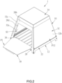
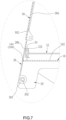
- the two second inner surfaces 32a of the second plates 32 face each other, wherein the second inner surface 32a of each of the second plates 32 obliquely abuts against one of the side edges 28c of each of the two first plates 28, and a distance between the two second inner surfaces 32a decreases upward along the height direction of the base 12, so that the two second plate 32 could be positioned without being held by the user.
- each of the two folded edges 32clocated on the two sides of the second plate 32 abuts against the first outer surface 28b of each of the two first plates 28, so that a gap between the adjacent first plate 28 and the adjacent second plate 32 could be closed.
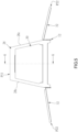
- each of the second plates 32 pivots in the direction away from the substrate 18, each of the second plates 32 could pivot to a second expanded position P22 as shown in FIG. 10 .
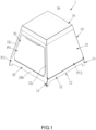
- the casing 10 further includes a top cover 34.
- the top cover 34 detachably fits around a top of each of the two first plates 28 and a top of each of the two second plates 32, so that a top of the baking space S1 could be closed by the top cover 34, and each of the second plates 32 could be restricted to the second assembled position P12 by the top cover 34.
- the heat source 36 (heater) of the oven 1 is disposed in the top cover 34, but not limited thereto. In other embodiments, the heat source 36, for example a heater or charcoals, could be placed on the substrate 18.
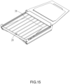
- the oven 1 further includes an oven rack 38, wherein the oven rack 38 could be disposed on the substrate 18.
- the baking object could be placed on the oven rack 38, or directly on the substrate 18 after oven rack 38 is removed from the substrate 18.
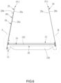
- each of the first plates 28 is pivotable relative to the base 12 to pivot to a first folded position P31
- each of the second plates 32 is pivotable relative to the base 12 to pivot to a second folded position P32.
- each of the second plate 32 could pivot to the second folded position P32.
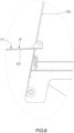
- the two second axes A2a, A2b are spaced apart from each other in the height direction of the base 12, the two second plate 32 could be stacked on the substrate 18, i.e., one of the second plates 32 abuts against the top surface 182 of the substrate 18, and the other second plate 32 abuts against the second outer surface 32b of the second plate 32.
- the first plate 28 pivots to the first folded position P31.
- the first plate 28 abuts against a bottom surface 186 of the substrate 18, and the first inner surface 28a of the first plate 28 is opposite to the bottom surface 186 of the substrate 18.
- the oven rack 38 is placed on the first plate 28.
- the first plate 28 having the door 30 pivots to the first folded position P31.
- the two first axes A1a, A1b are spaced apart from each other in the height direction of the base 12, the two first plates 28 could be stacked on the substrate 18.
- each of the first plates 28 is located below the substrate 18 and each of the second plates 32 is located above the substrate 18, so that a size of the casing 10 could be effectively reduced, thereby conducive to storing or bringing.
- the top cover 34 could be placed on the two second plates 32 for being stored or brought together.
- a casing 10 according to an alternative embodiment of the present invention is illustrated in FIG. 18 and has almost the same structure as that of the first embodiment, except that the height of the each of the two first pivot supports 24 of the alternative embodiment in the height direction of the base 12 is higher than that of the first embodiment, and the height of each of the second pivot supports 26 of the alternative embodiment in the height direction of the base 12 is higher than that of the first embodiment.
- a receiving space S3 is formed between the substrate 18 and one of the second plates 32 closer to the substrate 18 and is adapted to receive the top cover 34, so that a position of the top cover 34 could be restricted, thereby more conducive to storing and bringing the casing 10.
- the height of each of the second pivot supports 26 in the height direction of the base 12 could be further increased, so that the receiving space S3 could be formed between the two second plates 32 and be adapted to receive the top cover 34.
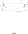
- FIG. 19 and FIG. 20 An oven 2 according to a second embodiment of the present invention is illustrated in FIG. 19 and FIG. 20 and further includes two supporting structures 40 disposed on an inside of the top cover 34 based on the first embodiment, wherein each of the two supporting structures 40 is located one of two opposite sides of the inside of the top cover 34.
- the top cover 34 fits around the top of each of the two first plates 28, the top of each of the two first plates 28 is inserted into a positioning groove 402 of one of the two supporting structures 40, so that each of the supporting structures 40 abuts the top of one of the two first plates 28.
- each of the first plates 28 is supported by one of the supporting structures 40, and a bottom of each of the first plate 28 is supported by one of the blocking portions 144 of the base 12, so that a strength of each of the first plates 28 could be increased.
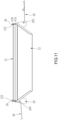
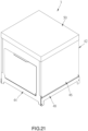
- FIG. 21 An oven 3 according to a third embodiment of the present invention is illustrated in FIG. 21 and has almost the same structure as that of the first embodiment, except that each of the first plates 44 and each of the second plates 46 of the casing 42 is a rectangular plate.
- a folded state of the casing 42 is the same as that of the first embodiment, i.e., the two first plates 44 are stacked on the bottom of the base 48, and the two second plates 46 are stacked on the top of the base 48, and therefore the folded state of the casing 42 is not repeated here.
- each of the first plates 44 stands straight to abut against one of the blocking portions 144 of the base 48 for positioning, but not limited thereto.
- each of the first plates 44 could be positioned through magnetic attraction or being stuck.
- the two supporting structures 40 of the second embodiment could be disposed in the inside of the top cover 50 of the casing 42 of the third embodiment to respectively support the top of one of the two first plates 44
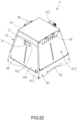
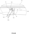
- FIG. 22 to FIG. 29 An oven 4 according to a fourth embodiment of the present invention is illustrated in FIG. 22 to FIG. 29 and has almost the same structure as that of the first embodiment, except that: A gas connector 542 is disposed on a rear side of the top cover 54 of the casing 52 and is connected between the heater and a gas source. Two anti-scald handles 56 are respectively connected to two sides of the top cover 54. The two anti-scald handles 56 could be made of thermal insulation materials, for example wood or Bakelite. The top cover 54 could be held through the two anti-scald handles 56.
- two grip pads 62 are respectively disposed on two sides of the base 60, wherein a thickness of each of the two grip pads 62 is greater than a thickness of plates located on the two sides of the base 60, so that a user could move the casing 52 more comfortably.
- An inside of the top cover 54 has at least two locking members 58 that are elastic. At least two of the top of the two first plates 64 and the top of the two second plates 66 have at least one locking hole 642a, 666.
- the at least two locking members 58 includes four locking members 58 respectively located at a position close to one of four corners of the top cover 54.
- Two sides of each of the first plates 64 respectively have a folded edge 642, wherein a top of each of the folded edges 642 has a locking hole 642a forming an open side on an edge of the corresponding folded edge 642.
- Two sides of each of the second plates 66 respectively have a locking hole 666 located at a position on the corresponding second plate 66 close to one of the folded edges 662.
- first outer surface 64a of each of the first plates 64 respectively have a recess 64b.
- An inside of each of the folded edges 662 of each of the second plates 66 has a protrusion 664. Both the recesses 64b and the protrusions 664 are formed by stamping.
- each of the protrusions 664 enters one of the recesses 64b for positioning by the protrusions matching with the recesses, so that each of the first plates 64 and each of the second plates 66 could not be easily moved due to an external force.
- the second plate 66 shown in FIG. 27 is partially removed for illustrating the locking hole 642a.
- Each of the locking holes 642a of the folded edges 642 of each of the first plates 64 corresponds to one of the locking holes 666 of one of the second plates 66.
- each of the locking members 58 could form a supporting structure, wherein each of the locking holes 642a of the folded edges 642 of each of the first plates 64 could abut against a side edge of one of the locking members 58. In this way, when each of the first plates 64 is pressed due to an external force, a hole edge of each of the locking holes 642a could abut against the side edge of one of the locking members 58, thereby increasing a strength of each of the first plates 64.
- each of the locking member 58 is pressed and the top cover 54 is lifted, so that the top cover 54 could be removed.
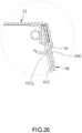
- the door 68 has a handle 70.
- the handle 70 is disposed on an outer surface 68a of the door 68 through a pivot support 72, wherein the handle 70 could be made of thermal insulation materials, for example wood or Bakelite.
- the pivot support 72 has a pivot 722 and a blocking rod 724.
- the handle 70 is pivotally connected to the pivot 722.
- the blocking rod 724 is located on a side of the pivot 722.
- the handle 70 is pivotable between a first position P41 and a second position P42. When the handle 70 is located at the first position P41, a free end 702 of the handle 70 is close to the door 68.
- the pivot degree ⁇ of the handle 70 between the first position P41 and the second position P42 is greater than 90°, preferably ranging between 110° and 130°. In the current embodiment, the pivot degree ⁇ substantially is 120°.
- the handle 70 could be pulled to pivot the door 68.
- the free end 702 of the handle 70 abuts against a loading surface F.
- the handle 70 forms a support of the door 68, so that the loading capacity of the door 68 is increased, thereby allowing a user to temporarily place objects, such as food, cooking utensils, or oven rack, on the opened door 68.
Landscapes
- Engineering & Computer Science (AREA)
- Chemical & Material Sciences (AREA)
- Combustion & Propulsion (AREA)
- Mechanical Engineering (AREA)
- General Engineering & Computer Science (AREA)
- Baking, Grill, Roasting (AREA)
Claims (14)
- Gehäuse (10, 42, 52) eines Ofens (1, 2, 3, 4), aufweisend:eine Basis (12, 48, 60), welche zwei erste Seitenabschnitte (14) und zwei zweite Seitenabschnitte (16) hat, wobei jeder von den zwei ersten Seitenabschnitten (14) zwei erste Schwenkabschnitte (142) hat; wobei jeder von den zwei zweiten Seitenabschnitten (16) zwei zweite Schwenkabschnitte (162) hat; wobei zwei erste Achsen (A1a, A1b) und zwei zweite Achsen (A2a, A2b) definiert sind, wobei jede von den zwei ersten Achsen (A1a, A1b) durch die zwei ersten Schwenkabschnitte (142) von einem von den zwei ersten Seitenabschnitten (14) hindurchgeht; wobei jede von den zwei zweiten Achsen (A2a, A2b) durch die zwei zweiten Schwenkabschnitte (162) von einem von den zwei zweiten Seitenabschnitten (16) hindurchgeht;zwei erste Platten (28, 44, 64), welche jeweils zwei erste Schwenkvorsprünge (282) haben, wobei jeder von den zwei ersten Schwenkvorsprüngen (282) von jeder von den zwei ersten Platten (28, 44, 64) in schwenkbarer Weise mit einem von den zwei ersten Schwenkabschnitten (142) von einem von den zwei ersten Seitenabschnitten (14) verbunden ist; wobei jede von den zwei ersten Platten (28, 44, 64) zwischen einer ersten zusammengeklappten Position (P31) und einer ersten zusammengebauten Position (P11) relativ zu der Basis (12, 48, 60) schwenkbar ist; undzwei zweite Platten (32, 46, 66), welche jeweils zwei zweite Schwenkvorsprünge (322) haben, wobei jede von den zwei zweiten Schwenkvorsprüngen (322) von jeder von den zwei zweiten Platten (32, 46, 66) in schwenkbarer Weise mit einem von den zwei zweiten Schwenkabschnitten (162) von einem von den zwei zweiten Seitenabschnitten (16) verbunden ist; wobei jede von den zwei zweiten Platten (32, 46, 66) zwischen einer zweiten zusammengeklappten Position (P32) und einer zweiten zusammengebauten Position (P12) relativ zu der Basis (12, 48, 60) schwenkbar ist;wobei, wenn jede von den zwei ersten Platten (28, 44, 64) hin zu der ersten zusammengebauten Position (P11) schwenkt und jede von den zwei zweiten Platten (32, 46, 66) hin zu der zweiten zusammengebauten Position (P12) schwenkt, die zwei ersten Platten (28, 44, 64) und die zwei zweiten Platten (32, 46, 66) gemeinsam umrahmend angeordnet sind, um einen Backraum (S1) zu bilden;wobei sich jede von den zwei ersten Achsen (A1a, A1b) und den zwei zweiten Achsen (A2a, A2b) in einer Höhenrichtung der Basis (12, 48, 60) im Abstand voneinander befinden;wobei, wenn jede von den zwei ersten Platten (28, 44, 64) hin zu der ersten zusammengeklappten Position (P31) schwenkt, die zwei ersten Platten (28, 44, 64) in der Höhenrichtung der Basis (12, 48, 60) gestapelt werden;wobei, wenn jede von den zwei zweiten Platten (32, 46, 66) hin zu der zweiten zusammengeklappten Position (P32) schwenkt, die zwei zweiten Platten (32, 46, 66) in der Höhenrichtung der Basis (12, 48, 60) gestapelt werden;wobei die Basis (12, 48, 60) ein Substrat (18) aufweist; wobei sich die zwei ersten Schwenkabschnitte (142) unterhalb des Substrats (18) befinden, und sich die zwei zweiten Schwenkabschnitte (162) oberhalb des Substrats (18) befinden;wobei, wenn jede von den zwei ersten Platten (28, 44, 64) hin zu der ersten zusammengeklappten Position (P31) schwenkt, sich jede von den zwei ersten Platten (28, 44, 64) unterhalb des Substrats (18) befindet; wobei, wenn jede von den zwei zweiten Platten (32, 46, 66) hin zu der zweiten zusammengeklappten Position (P32) schwenkt, sich jede von den zwei zweiten Platten (32, 46, 66) oberhalb des Substrats (18) befindet.
- Gehäuse (10, 42, 52) des Ofens (1, 2, 3, 4) gemäß Anspruch 1, wobei die zwei ersten Seitenabschnitte (14) in jeweils zugeordneter Weise an zwei entgegengesetzten Seiten der Basis (12, 48, 60) angeordnet sind; wobei jede von den zwei ersten Platten (28, 44, 64) eine erste innere Fläche (28a) und zwei Seitenränder (28c) hat; wobei jede von den zwei zweiten Platten (32, 46, 66) eine zweite innere Fläche (32a) hat; wobei jeder von den zwei ersten Seitenabschnitten (14) der Basis (12, 48, 60) einen Blockierungsabschnitt (144) hat; wobei, wenn jede von den zwei ersten Platten (28, 44, 64) hin zu der ersten zusammengebauten Position (P11) schwenkt, jede von den zwei ersten Platten (28, 44, 64) an dem Blockierungsabschnitt (144) von einem von den zwei ersten Seitenabschnitten (14) anliegt zur Positionierung; wobei, wenn jede von den zwei ersten Platten (28, 44, 64) hin zu der ersten zusammengebauten Position (P11) schwenkt und jede von den zwei zweiten Platten (32, 46, 66) hin zu der zweiten zusammengebauten Position (P12) schwenkt, die erste innere Fläche (28a) von jeder von den zwei ersten Platten (28, 44, 64) der ersten inneren Fläche (28a) von der anderen ersten Platte (28, 44, 64) zugewandt ist, und die zweite innere Fläche (32a) von jeder von den zwei zweiten Platten (32, 46, 66) der zweiten inneren Fläche (32a) von der anderen zweiten Platte (32, 46, 66) zugewandt ist und an einer von den zwei Seitenrändern (28c) von jeder von den zwei ersten Platten (28, 44, 64) anliegt.
- Gehäuse (10, 42, 52) des Ofens (1, 2, 3, 4) gemäß Anspruch 2, wobei die Basis (12, 48, 60) zwei erste Schwenklager (24), zwei zweite Schwenklager (26), eine erste Stützplatte (20) und eine zweite Stützplatte (22) aufweist, wobei die zwei ersten Schwenklager (24) mit einer oberen Fläche (182) des Substrats (18) in Eingriff stehen und einen von den zwei zweiten Schwenkabschnitten (162) bilden; wobei die zwei zweiten Schwenklager (26) mit der oberen Fläche (182) des Substrats (18) in Eingriff stehen, sich an einer Seite der oberen Fläche (182) des Substrats (18), welche entgegengesetzt zu den zwei ersten Schwenklagern (24) ist, befinden und den anderen zweiten Schwenkabschnitt (162) bilden; wobei die erste Stützplatte (20) und die zweite Stützplatte (22) in jeweils zugeordneter Weise mit zwei entgegengesetzten Seitenrändern (184) des Substrats (18) in Eingriff stehen; wobei ein Ende der ersten Stützplatte (20) und ein Ende der zweiten Stützplatte (22) einen von den zwei ersten Schwenkabschnitten (142) bilden, und ein anderes Ende der ersten Stützplatte (20) und ein anderes Ende der zweiten Stützplatte (22) den anderen ersten Schwenkabschnitt (142) bilden.
- Gehäuse (10, 42, 52) des Ofens (1, 2, 3, 4) gemäß Anspruch 2, wobei, wenn jede von den zwei ersten Platten (28, 44, 64) hin zu der ersten zusammengebauten Position (P11) schwenkt, jede von den zwei ersten Platten (28, 44, 64) in schräger Weise an dem Blockierungsabschnitt (144) von einem von den zwei ersten Seitenabschnitten (14) anliegt zur Positionierung.
- Gehäuse (10, 42, 52) des Ofens (1, 2, 3, 4) gemäß Anspruch 4, wobei eine von den zwei ersten Platten (28, 44, 64) einen Einlass (28d) und eine Tür (30, 68) hat, welche schwenkbar ist; wobei, wenn die erste Platte (28, 44, 64) hin zu der ersten zusammengebauten Position (P11) schwenkt, die Tür (30, 68) zwischen einer geschlossenen Position (P0) und einer offenen Position (P1) schwenkbar ist; wobei, wenn sich die Tür (30, 68) an der geschlossenen Position (P0) befindet, die Tür (30, 68) in schräger Weise an der ersten Platte (28, 44, 64) anliegt und den Einlass (28d) verschließt; wobei, wenn sich die Tür (30, 68) an der offenen Position (P1) befindet, der Einlass (28d) geöffnet ist.
- Gehäuse (52) des Ofens (4) gemäß Anspruch 5, wobei ein Handgriff (70) an der Tür (68) angeordnet ist und zwischen einer ersten Position (P41) und einer zweiten Position (P42) schwenkbar ist; wobei, wenn sich der Handgriff (70) an der ersten Position (P41) befindet, sich ein freies Ende (702) des Handgriffs (70) nahe zu der Tür (68) befindet; wobei, wenn sich der Handgriff (70) an der zweiten Position (P42) befindet, das freie Ende (702) des Handgriffs (70) von der Tür (68) entfernt gelegen ist; wobei, wenn sich die Tür (68) an der offenen Position (P1) befindet und sich der Handgriff (70) an der zweiten Position (P42) befindet, das freie Ende (702) angepasst ist, um an einer Lastaufnahmefläche (F) anzuliegen.
- Gehäuse (10, 42, 52) des Ofens (1, 2, 3, 4) gemäß Anspruch 2, wobei das Substrat (18) zwei Seitenränder (184) aufweist, welche in jeweils zugeordneter Weise den Blockierungsabschnitt (144) von einem von den zwei ersten Seitenabschnitten (14) bilden.
- Gehäuse (52) des Ofens (4) gemäß Anspruch 2, wobei jede von den zwei ersten Platten (64) eine erste äußere Fläche (64a) hat, wobei zwei Seiten von jeder von den zwei zweiten Platten (66) jeweils einen umgebogenen Rand (662) haben; wobei, wenn jede von den zwei ersten Platten (64) hin zu der ersten zusammengebauten Position (P11) schwenkt und jede von den zwei zweiten Platten (66) hin zu der zweiten zusammengebauten Position (P12) schwenkt, jeder von den zwei umgebogenen Rändern (662) von jeder von den zwei zweiten Platten (66) an der ersten äußeren Fläche (64a) von jeder von den zwei ersten Platten (64) anliegt.
- Gehäuse (52) des Ofens (4) gemäß Anspruch 8, wobei eine Innenseite von jedem von den zwei umgebogenen Rändern (662) von jeder von den zwei zweiten Platten (66) einen Vorsprung (664) hat; wobei zwei Seiten von der ersten äußeren Fläche (64a) von jeder von den zwei ersten Platten (64) jeweils eine Ausnehmung (64b) haben; wobei, wenn jede von den zwei ersten Platten (64) hin zu der ersten zusammengebauten Position (P11) schwenkt und jede von den zwei zweiten Platten (66) hin zu der zweiten zusammengebauten Position (P12) schwenkt, jeder von den Vorsprüngen (664) mit einer von den Ausnehmungen (64b) zusammenpasst zur Positionierung.
- Gehäuse (10, 42, 52) des Ofens (1, 2, 3, 4) gemäß Anspruch 1, welches ferner eine obere Abdeckung (34, 50, 54) aufweist, wobei, wenn jede von den zwei ersten Platten (28, 44, 64) hin zu der ersten zusammengebauten Position (P11) schwenkt und jede von den zwei zweiten Platten (32, 46, 66) hin zu der zweiten zusammengebauten Position (P12) schwenkt, die obere Abdeckung (34, 50, 54) in abnehmbarer Weise um eine obere Seite von jeder von den zwei ersten Platten (28, 44, 64) und eine obere Seite von jeder von den zwei zweiten Platten (32, 46, 66) herumpasst; wobei, wenn jede von den zwei zweiten Platten (32, 46, 66) hin zu der zweiten zusammengeklappten Position (P32) schwenkt, ein Aufnahmeraum (S3) zwischen dem Substrat (18) und einer von den zwei zweiten Platten (32, 46, 66) gebildet wird und dafür geeignet ist, die obere Abdeckung (34, 50, 54) aufzunehmen.
- Gehäuse (10, 42, 52) des Ofens (1, 2, 3, 4) gemäß Anspruch 1, welches ferner eine obere Abdeckung (34, 50, 54) aufweist, wobei, wenn jede von den zwei ersten Platten (28, 44, 64) hin zu der ersten zusammengebauten Position (P11) schwenkt und jede von den zwei zweiten Platten (32, 46, 66) hin zu der zweiten zusammengebauten Position (P12) schwenkt, die obere Abdeckung in abnehmbarer Weise um eine obere Seite von jeder von den zwei ersten Platten (28, 44, 64) und eine obere Seite von jeder von den zwei zweiten Platten (32, 46, 66) herumpasst; wobei, wenn jede von den zwei zweiten Platten (32, 46, 66) hin zu der zweiten zusammengeklappten Position (P32) schwenkt, ein Aufnahmeraum (S3) zwischen den zwei zweiten Platten (32, 46, 66) gebildet wird und dafür geeignet ist, die obere Abdeckung (34, 50, 54) aufzunehmen.
- Gehäuse (10, 42, 52) des Ofens (1, 2, 3, 4) gemäß Anspruch 1, welches ferner eine obere Abdeckung (34, 50, 54) aufweist, wobei, wenn jede von den zwei ersten Platten (28, 44, 64) hin zu der ersten zusammengebauten Position (P11) schwenkt und jede von den zwei zweiten Platten (32, 46, 66) hin zu der zweiten zusammengebauten Position (P12) schwenkt, die obere Abdeckung (34, 50, 54) in abnehmbarer Weise um eine obere Seite von jeder von den zwei ersten Platten (28, 44, 64) und eine obere Seite von jeder von den zwei zweiten Platten (32, 46, 66) herumpasst.
- Gehäuse (10) des Ofens (2) gemäß Anspruch 12, wobei eine Innenseite der oberen Abdeckung (34) zwei Lagerstrukturen (40) hat; wobei, wenn die obere Abdeckung (34) um die obere Seite von jeder von den zwei ersten Platten (28) herumpasst, jede von den zwei Lagerstrukturen (40) eine von den zwei ersten Platten (28) blockiert.
- Gehäuse (52) des Ofens (4) gemäß Anspruch 12, wobei eine Innenseite der oberen Abdeckung (54) mindestens zwei Verriegelungselemente (58) hat; wobei mindestens zwei von den oberen Seiten von den zwei ersten Platten (64) und den oberen Seiten von den zwei zweiten Platten (66) mindestens ein Verriegelungsloch (642a, 666) haben; wobei, wenn die obere Abdeckung (54) um die obere Seite von jeder von den zwei ersten Platten (64) und die obere Seite von jeder von den zwei zweiten Platten (66) herumpasst, jedes von den mindestens zwei Verriegelungselementen (58) entweder in das mindestens eine Verriegelungsloch (642a, 666) von einer von den zwei ersten Platten (64) oder in das mindestens eine Verriegelungsloch (642a, 666) von einer von den zwei zweiten Platten (66) eintritt.
Priority Applications (1)
| Application Number | Priority Date | Filing Date | Title |
|---|---|---|---|
| EP23177923.2A EP4474708B1 (de) | 2023-06-07 | 2023-06-07 | Ofengehäuse |
Applications Claiming Priority (1)
| Application Number | Priority Date | Filing Date | Title |
|---|---|---|---|
| EP23177923.2A EP4474708B1 (de) | 2023-06-07 | 2023-06-07 | Ofengehäuse |
Publications (3)
| Publication Number | Publication Date |
|---|---|
| EP4474708A1 EP4474708A1 (de) | 2024-12-11 |
| EP4474708C0 EP4474708C0 (de) | 2025-07-02 |
| EP4474708B1 true EP4474708B1 (de) | 2025-07-02 |
Family
ID=86732105
Family Applications (1)
| Application Number | Title | Priority Date | Filing Date |
|---|---|---|---|
| EP23177923.2A Active EP4474708B1 (de) | 2023-06-07 | 2023-06-07 | Ofengehäuse |
Country Status (1)
| Country | Link |
|---|---|
| EP (1) | EP4474708B1 (de) |
Family Cites Families (3)
| Publication number | Priority date | Publication date | Assignee | Title |
|---|---|---|---|---|
| GB189647A (en) * | 1921-12-02 | 1922-12-07 | Alexander John Marsh | Improvements on gas cookers |
| TW564736U (en) * | 2002-08-01 | 2003-12-01 | Ting Chin Ind Co Ltd | Foldable BBQ stove |
| KR200390591Y1 (ko) * | 2005-04-29 | 2005-07-21 | 이영민 | 휴대용버너의 바람막이 |
-
2023
- 2023-06-07 EP EP23177923.2A patent/EP4474708B1/de active Active
Also Published As
| Publication number | Publication date |
|---|---|
| EP4474708C0 (de) | 2025-07-02 |
| EP4474708A1 (de) | 2024-12-11 |
Similar Documents
| Publication | Publication Date | Title |
|---|---|---|
| AU2019226181B2 (en) | Room service table | |
| US20090165771A1 (en) | Foldable and removable side table for bbq grill | |
| US20140246418A1 (en) | Toaster Oven with Improved Access to Cooking Cavity | |
| EP4474708B1 (de) | Ofengehäuse | |
| EP4474709A1 (de) | Ofengehäuse | |
| JP2004261280A (ja) | グリル | |
| US20130298896A1 (en) | Combinational portable cooking device | |
| US8739772B2 (en) | Grill with multi-sided access | |
| TWM647067U (zh) | 烤箱之箱體 | |
| US20240407598A1 (en) | Casing of oven | |
| TWI840166B (zh) | 烤箱之箱體 | |
| TWI840165B (zh) | 烤箱之箱體 | |
| CN220158105U (zh) | 烤箱的箱体 | |
| CN220236670U (zh) | 烤箱的箱体 | |
| TWM647700U (zh) | 烤箱之箱體 | |
| CN220546175U (zh) | 一种烧烤装置 | |
| CN220459209U (zh) | 一种便于收纳的空气炸锅 | |
| CN223569205U (zh) | 一种方便收纳的烧烤架 | |
| CN110150821B (zh) | 一种军用便捷餐盒 | |
| CN217309951U (zh) | 一种烤盘和带有此烤盘的空气炸锅 | |
| US20250176761A1 (en) | Frying pan, frying basket assembly and air fryer | |
| CN215686961U (zh) | 烹饪器具 | |
| CN218219960U (zh) | 一种可折叠式烧烤炉 | |
| CN223773512U (zh) | 烹饪器具 | |
| JP2025162909A (ja) | ホットプレート |
Legal Events
| Date | Code | Title | Description |
|---|---|---|---|
| PUAI | Public reference made under article 153(3) epc to a published international application that has entered the european phase |
Free format text: ORIGINAL CODE: 0009012 |
|
| STAA | Information on the status of an ep patent application or granted ep patent |
Free format text: STATUS: REQUEST FOR EXAMINATION WAS MADE |
|
| 17P | Request for examination filed |
Effective date: 20240716 |
|
| AK | Designated contracting states |
Kind code of ref document: A1 Designated state(s): AL AT BE BG CH CY CZ DE DK EE ES FI FR GB GR HR HU IE IS IT LI LT LU LV MC ME MK MT NL NO PL PT RO RS SE SI SK SM TR |
|
| GRAP | Despatch of communication of intention to grant a patent |
Free format text: ORIGINAL CODE: EPIDOSNIGR1 |
|
| STAA | Information on the status of an ep patent application or granted ep patent |
Free format text: STATUS: GRANT OF PATENT IS INTENDED |
|
| INTG | Intention to grant announced |
Effective date: 20250103 |
|
| GRAS | Grant fee paid |
Free format text: ORIGINAL CODE: EPIDOSNIGR3 |
|
| GRAA | (expected) grant |
Free format text: ORIGINAL CODE: 0009210 |
|
| STAA | Information on the status of an ep patent application or granted ep patent |
Free format text: STATUS: THE PATENT HAS BEEN GRANTED |
|
| AK | Designated contracting states |
Kind code of ref document: B1 Designated state(s): AL AT BE BG CH CY CZ DE DK EE ES FI FR GB GR HR HU IE IS IT LI LT LU LV MC ME MK MT NL NO PL PT RO RS SE SI SK SM TR |
|
| REG | Reference to a national code |
Ref country code: GB Ref legal event code: FG4D |
|
| REG | Reference to a national code |
Ref country code: CH Ref legal event code: EP |
|
| REG | Reference to a national code |
Ref country code: DE Ref legal event code: R096 Ref document number: 602023004455 Country of ref document: DE |
|
| REG | Reference to a national code |
Ref country code: IE Ref legal event code: FG4D |
|
| U01 | Request for unitary effect filed |
Effective date: 20250714 |
|
| U07 | Unitary effect registered |
Designated state(s): AT BE BG DE DK EE FI FR IT LT LU LV MT NL PT RO SE SI Effective date: 20250718 |
|
| PG25 | Lapsed in a contracting state [announced via postgrant information from national office to epo] |
Ref country code: IS Free format text: LAPSE BECAUSE OF FAILURE TO SUBMIT A TRANSLATION OF THE DESCRIPTION OR TO PAY THE FEE WITHIN THE PRESCRIBED TIME-LIMIT Effective date: 20251102 |
|
| PG25 | Lapsed in a contracting state [announced via postgrant information from national office to epo] |
Ref country code: NO Free format text: LAPSE BECAUSE OF FAILURE TO SUBMIT A TRANSLATION OF THE DESCRIPTION OR TO PAY THE FEE WITHIN THE PRESCRIBED TIME-LIMIT Effective date: 20251002 |
|
| PG25 | Lapsed in a contracting state [announced via postgrant information from national office to epo] |
Ref country code: HR Free format text: LAPSE BECAUSE OF FAILURE TO SUBMIT A TRANSLATION OF THE DESCRIPTION OR TO PAY THE FEE WITHIN THE PRESCRIBED TIME-LIMIT Effective date: 20250702 |
|
| PG25 | Lapsed in a contracting state [announced via postgrant information from national office to epo] |
Ref country code: GR Free format text: LAPSE BECAUSE OF FAILURE TO SUBMIT A TRANSLATION OF THE DESCRIPTION OR TO PAY THE FEE WITHIN THE PRESCRIBED TIME-LIMIT Effective date: 20251003 |
|
| PG25 | Lapsed in a contracting state [announced via postgrant information from national office to epo] |
Ref country code: CZ Free format text: LAPSE BECAUSE OF FAILURE TO SUBMIT A TRANSLATION OF THE DESCRIPTION OR TO PAY THE FEE WITHIN THE PRESCRIBED TIME-LIMIT Effective date: 20250702 |
|
| PG25 | Lapsed in a contracting state [announced via postgrant information from national office to epo] |
Ref country code: PL Free format text: LAPSE BECAUSE OF FAILURE TO SUBMIT A TRANSLATION OF THE DESCRIPTION OR TO PAY THE FEE WITHIN THE PRESCRIBED TIME-LIMIT Effective date: 20250702 |
|
| PG25 | Lapsed in a contracting state [announced via postgrant information from national office to epo] |
Ref country code: RS Free format text: LAPSE BECAUSE OF FAILURE TO SUBMIT A TRANSLATION OF THE DESCRIPTION OR TO PAY THE FEE WITHIN THE PRESCRIBED TIME-LIMIT Effective date: 20251002 |
|
| PG25 | Lapsed in a contracting state [announced via postgrant information from national office to epo] |
Ref country code: ES Free format text: LAPSE BECAUSE OF FAILURE TO SUBMIT A TRANSLATION OF THE DESCRIPTION OR TO PAY THE FEE WITHIN THE PRESCRIBED TIME-LIMIT Effective date: 20250702 |
|
| PG25 | Lapsed in a contracting state [announced via postgrant information from national office to epo] |
Ref country code: SM Free format text: LAPSE BECAUSE OF FAILURE TO SUBMIT A TRANSLATION OF THE DESCRIPTION OR TO PAY THE FEE WITHIN THE PRESCRIBED TIME-LIMIT Effective date: 20250702 |