EP4474709A1 - Ofengehäuse - Google Patents
Ofengehäuse Download PDFInfo
- Publication number
- EP4474709A1 EP4474709A1 EP23177894.5A EP23177894A EP4474709A1 EP 4474709 A1 EP4474709 A1 EP 4474709A1 EP 23177894 A EP23177894 A EP 23177894A EP 4474709 A1 EP4474709 A1 EP 4474709A1
- Authority
- EP
- European Patent Office
- Prior art keywords
- plates
- pivot
- pivots
- casing
- oven
- Prior art date
- Legal status (The legal status is an assumption and is not a legal conclusion. Google has not performed a legal analysis and makes no representation as to the accuracy of the status listed.)
- Pending
Links
- 230000000903 blocking effect Effects 0.000 claims abstract description 19
- 239000000758 substrate Substances 0.000 claims description 46
- 210000005069 ears Anatomy 0.000 claims description 14
- 238000000034 method Methods 0.000 abstract description 4
- 230000007423 decrease Effects 0.000 description 4
- 206010053615 Thermal burn Diseases 0.000 description 3
- 229920001342 Bakelite® Polymers 0.000 description 2
- 239000004637 bakelite Substances 0.000 description 2
- 239000012774 insulation material Substances 0.000 description 2
- 239000002023 wood Substances 0.000 description 2
- 238000010411 cooking Methods 0.000 description 1
- 239000002184 metal Substances 0.000 description 1
Images


Classifications
-
- F—MECHANICAL ENGINEERING; LIGHTING; HEATING; WEAPONS; BLASTING
- F24—HEATING; RANGES; VENTILATING
- F24C—DOMESTIC STOVES OR RANGES ; DETAILS OF DOMESTIC STOVES OR RANGES, OF GENERAL APPLICATION
- F24C1/00—Stoves or ranges in which the fuel or energy supply is not restricted to solid fuel or to a type covered by a single one of the following groups F24C3/00 - F24C9/00; Stoves or ranges in which the type of fuel or energy supply is not specified
- F24C1/16—Stoves or ranges in which the fuel or energy supply is not restricted to solid fuel or to a type covered by a single one of the following groups F24C3/00 - F24C9/00; Stoves or ranges in which the type of fuel or energy supply is not specified with special adaptation for travelling, e.g. collapsible
-
- F—MECHANICAL ENGINEERING; LIGHTING; HEATING; WEAPONS; BLASTING
- F24—HEATING; RANGES; VENTILATING
- F24B—DOMESTIC STOVES OR RANGES FOR SOLID FUELS; IMPLEMENTS FOR USE IN CONNECTION WITH STOVES OR RANGES
- F24B1/00—Stoves or ranges
- F24B1/20—Ranges
- F24B1/202—Ranges specially adapted for travelling
- F24B1/205—Ranges specially adapted for travelling collapsible
Definitions
- the present invention relates generally to a casing of an oven, and more particularly to a casing, which could be disassembled and assembled.
- a conventional oven includes a casing and a heater, wherein the casing has a baking space therein adapted to receive a baking object.
- the heater is disposed in the casing and is adapted to heat the baking space, so that the baking object is heated in the baking space.
- the casing of the oven is constituted of a plurality of plates and the plates are fixed to one another, the shape of the casing is fixed and the casing occupies a considerable space, and thus a user is required to carry the casing upon moving the oven, thereby causing inconvenience in moving the oven.
- a larger storage space is required to store the casing of the oven.
- the oven Due to the inconvenience in moving and storing the oven, the oven is generally disposed and used at a fixed position in home, and is seldomly brought and used during outdoor camping.
- the conventional oven still has room for improvement.
- the primary objective of the present invention is to provide a casing of an oven which could be disassembled and assembled, wherein when the casing is assembled, at least two plates could be positioned, thereby facilitating the assembling process.
- the present invention provides a casing of an oven including a base, two first plates, and two second plate.
- the base has two first side portions and two second side portions, wherein each of the two first side portions has a blocking portion and two first pivot portions located below the blocking portion.
- Each of the two second side portions has two second pivot portions.
- Each of the two first plates has two first pivot ears, wherein each of the two first pivot ears of each of the two first plates is pivotally connected to one of the two first pivot portions of one of the two first side portions.
- Each of the two first plates is pivotable relative to the base. When each of the two first plates pivots to a first assembled position, each of the two first plates obliquely abuts against the blocking portion of one of the two first side portions for positioning.
- the two second plates respectively have two first pivot ears, wherein each of the two second pivot ears of each of the two second plates is pivotally connected to one of the two second pivot portions of one of the two second side portions.
- Each of the two second plates is pivotable relative to the base.
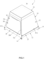
- FIG. 1 to FIG. 17 An oven 1 according to a first embodiment of the present invention is illustrated in FIG. 1 to FIG. 17 and includes a casing 10 and a heat source 36, wherein the casing 10 is adapted to receive a baking object therein.
- the heat source 36 is adapted to heat an inside of the casing 10.
- the heat source 36 could be, for example, charcoals or a heater such as a gas burner or an electric heater, .
- the casing 10 includes a base 12, two first plates 28, and two second plates 32.
- the base 12 has four side portions including two first side portions 14 and two second side portions 16.
- the two first side portions 14 are respectively located on two opposite sides of the base 12, and the two second side portions 16 are respectively located on another two opposite sides of the base 12 and between the two first side portions 14, but not limited thereto.
- one of the first side portions 14 and one of the second side portions 16 are respectively located on the two opposite sides of the base 12, and the other first side portion 14 and the other second side portion 16 are respectively located on the another two opposite sides of the base 12.
- Each of the first side portions 14 has a blocking portion 144 and two first pivot portions 142 located below the blocking portion 144.
- Each of the second side portions 16 has two second pivot portions 162.
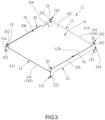
- the base 12 includes a substrate 18, a first support plate 20, a second support plate 22, two first pivot supports 24, and two second pivot supports 26.
- the substrate 18 is a rectangular plate and has four side edges 184, wherein two of the opposite side edges 184 of the substrate 18 respectively constitute the blocking portion 144 of one of the two first side portions 14, and the other two opposite side edges 184 of the substrate 18 are respectively engaged with the first support plate 20 and the second support plate 22.
- An end of the first support plate 20 has a first pivot hole 202, and another end of the first support plate 20 has a second pivot hole 204.
- An end of the second support plate 22 has a first pivot hole 222, and another end of the second support plate 22 has a second pivot hole 224.
- the first pivot hole 202 of the first support plate 20 and the first pivot hole 222 of the second support plate 22 face each other.
- the second pivot hole 204 of the first support plate 20 and the second pivot hole 224 of the second support plate 22 face each other.
- a position of the first pivot hole 202 of the first support plate 20 and a position of the first pivot hole 222 of the second support plate 22 are higher than a position of the second pivot hole 204 of the first support plate 20 and a position of the second pivot hole 224 of the second support plate 22 in a height direction of the base 12.
- first support plate 20 and the end of the second support plate 22 constitute one of the first pivot portions 142
- the another end of the first support plate 20 and the another end of the second support plate 22 constitute the other first pivot portion 142, so that the first support plate 20 and the second support plate 22 jointly have the two first pivot portions 142 located below the substrate 18.
- Two first axes A1a, A1b are defined, wherein one of the first axes A1a passes through the two first pivot holes 202 ,222, and the other first axis A1b passes through the two second pivot holes 204 ,224.
- each of the two first axes A1a, A1b passes through the two first pivot portions 142 of one of the two first side portions 14, and the two first axes A1a, A1b are spaced apart from each other.
- the two first pivot supports 24 and the two second pivot supports 26 are respectively disposed on four corners of a top surface 182 of the substrate 18, wherein the two first pivot supports 24 are close to the first support plate 20, and the two second pivot supports 26 are close to the second support plate 22.
- the two first pivot supports 24 are engaged with the top surface 182 of the substrate 18 to constitute one of the second pivot portions 162.
- Each of the first pivot supports 24 has a first pivot hole 242, wherein the two first pivot hole 242 of the first pivot supports 24 face each other.
- the two second pivot supports 26 are engaged with the top surface 182 of the substrate 18 and are located on a side of the top surface 182 of the substrate 18 opposite to the two first pivot supports 24.
- the two second pivot supports 26 constitute the other second pivot portion 162.
- Each of the second pivot supports 26 has a second pivot hole 262, wherein the two second pivot holes 262 of the first pivot supports 24 face each other. Positions of the two second pivot holes 262 of the second pivot supports 26 are higher than position of the two first pivot holes 242 of the first pivot supports 24 in the height direction of the base 12. In this way, the two first pivot supports 24 and the two second pivot supports 26 respectively form one of the two second pivot portions 162 located on a top of the substrate 18.
- Two second axes A2a, A2b are defined, wherein one of the second axes A2a passes through the two first pivot holes 242 of the first pivot supports 24, and the other second axis A2b passes through the two second pivot holes 262 of the second pivot supports 26.
- each of the second axes A2a, A2b passes through the two second pivot portions 162 of one of the second side portions 16.
- the two second axes A2a, A2b are spaced apart from each other and the two first axes A1a, A1b.
- a height of each of the second pivot supports 26 in the height direction of the base 12 is greater than a height of each of the first pivot supports 24 in the height direction of the base 12.
- the first support plate 20 has an extending section 206 extending upward to be higher than the top surface 182 of the substrate 18 in the height direction of the substrate 18 and be located between the two first pivot supports 24, so that the extending section 206 of the first support plate 20 covers a gap between the two first pivot supports 24.
- the second support plate 22 has an extending section 226 extending upward to be higher than the top surface 182 of the substrate 18 in the height direction of the substrate 18 and be located between the two second pivot supports 26, so that the extending section 226 of the second support plate 22 covers a gap between the two second pivot supports 26.
- a height of the extending section 226 of the second support plate 22 in the height direction of the base 12 is greater than a height of the extending section 206 of the first support plate 20 in the height direction of the base 12.
- each of the first plates 28 has two first pivot ears 282 respectively and pivotally connected to one of the two first pivot portions 142 of one of the first side portions 14, so that each of the first plates 28 is pivotable relative to the base 12. More specifically, each of the two first pivot ears 282 of one of the first plates 28 is pivotally connected to either the first pivot hole 202 of the first support plate 20 or the first pivot hole 222 of the second support plate 22, and each of the first pivot ears 282 of the other first plate 28 is pivotally connected to either the second pivot hole 204 of the first support plate 20 or the second pivot hole 224 of the second support plate 22.
- Each of the first plates 28 has a first inner surface 28a, a first outer surface 28b, and two side edges 28c.
- each of the first plates 28 is a trapezoidal plate, wherein each of the side edges 28c is an oblique side edge of the trapezoid, and a distance between the two side edges 28c decreases upward along the height direction of the base 12.
- each of the first plates 28 When each of the first plates 28 pivots to a first assembled position P11, each of the first plates 28 obliquely abuts against one of the blocking portions 144 for positioning, i.e., the inner surface 28a of each of the first plates 28 abuts against one of the side edges 184 of the substrate 18, so that each of the first plates 28 could be firmly positioned due to a weight of each of the first plates 28 without being held by a user.
- the two first inner surfaces 28a of the first plates 28 face each other, and a distance between the two first inner surface 28a gradually decrease upward along the height direction of the base 12.
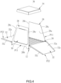
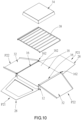
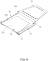
- each of the first plates 28 When each of the first plate 28 pivots in a direction away from the substrate 18, each of the first plates 28 could pivot to a first expanded position P21 as shown in FIG. 10 .
- each of the first plates 28 could be positioned in a way other than obliquely abutting against one of the blocking portions 144, for example magnetic attraction or being stuck.
- one of the first plates 28 located on a front side of the oven 1 has entrance 28d, a door 30 which is pivotable is disposed on the first plate 28.
- the door 30 is pivotable between a closed position P0 and an open position P1.
- the door 30 obliquely abuts against the first plate 28 and closes the entrance 28d.
- the entrance 28d could be firmly closed due to a weight of the door 30.
- the door 30 when the door 30 is located at the open position P1, the entrance 28d is opened, and an outer surface 302 of the door 30 abuts against a bottom edge of the entrance 28d for positioning. At that time, the door 30 is supported by the first plate 28 to be located at a position higher than the base 12 in the height direction of the base 12. In this way, when the casing 10 is disposed on a loading surface having a small area, the door 30 could be suspended without being supported by the loading surface.
- Each of the second plates 32 has two second pivot ears 322 respectively and pivotally connected to one of the two second pivot portions 162 of one of the two second side portions 16, so that each of the second plates 32 is pivotable relative to the base 12. More specifically, each of the two second pivot ears 322 of one of the second plates 32 is pivotally connected to one of the two first pivot holes 242 of the first pivot support 24, and each of the two second pivot ears 322 of the other second plate 32 is pivotally connected to one of the two second pivot holes 262 of the second pivot support 26.
- Each of the second plates 32 has a second inner surface 32a, a second outer surface 32b, and two folded edges 32c.
- each of the second plates 32 is a trapezoidal plate, wherein each of the two folded edges 32c is located on one of two sides of each of the second plates 32, and a distance between the two folded edges 32c of each of the second plates 32 decreases upward along the height direction of the base 12.
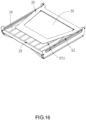
- FIG. 1 and FIG. 2 when each of the first plates 28 pivots to the first assembled position P11 and each of the second plates 32 pivots to a second assembled position P12, the two second plates 32 and the two first plates 28 jointly surround to form a baking space S1.
- the two second inner surfaces 32a of the second plates 32 face each other, wherein the second inner surface 32a of each of the second plates 32 obliquely abuts against one of the side edges 28c of each of the two first plates 28, and a distance between the two second inner surfaces 32a decreases upward along the height direction of the base 12, so that the two second plate 32 could be positioned without being held by the user.
- each of the two folded edges 32clocated on the two sides of the second plate 32 abuts against the first outer surface 28b of each of the two first plates 28, so that a gap between the adjacent first plate 28 and the adjacent second plate 32 could be closed.
- each of the second plates 32 pivots in the direction away from the substrate 18, each of the second plates 32 could pivot to a second expanded position P22 as shown in FIG. 10 .
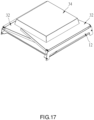
- the casing 10 further includes a top cover 34.
- the top cover 34 detachably fits around a top of each of the two first plates 28 and a top of each of the two second plates 32, so that a top of the baking space S1 could be closed by the top cover 34, and each of the second plates 32 could be restricted to the second assembled position P12 by the top cover 34.
- the heat source 36 (heater) of the oven 1 is disposed in the top cover 34, but not limited thereto. In other embodiments, the heat source 36, for example a heater or charcoals, could be placed on the substrate 18.
- the base 12, the two first plates 28, the two second plates 32, the door 30, and the top cover 34 are respectively made of a metal plate.
- the oven 1 further includes an oven rack 38, wherein the oven rack 38 could be disposed on the substrate 18.
- the baking object could be placed on the oven rack 38, or directly on the substrate 18 after oven rack 38 is removed from the substrate 18.
- the baking object having a size larger than a size of the entrance 28d could be placed on the substrate 18 or the oven rack 38, and then each of the two first plates 28 is moved to the first assembled position P11 and each of the two second plates 32 is moved to the second assembled position P12, so that the baking object having the large size could be placed in the baking space S 1.
- each of the first plates 28 is pivotable relative to the base 12 to pivot to a first folded position P31
- each of the second plates 32 is pivotable relative to the base 12 to pivot to a second folded position P32.
- each of the second plate 32 could pivot to the second folded position P32.
- the two second axes A2a, A2b are spaced apart from each other in the height direction of the base 12, the two second plate 32 could be stacked on the substrate 18, i.e., one of the second plates 32 abuts against the top surface 182 of the substrate 18, and the other second plate 32 abuts against the second outer surface 32b of the second plate 32.
- the first plate 28 pivots to the first folded position P31.
- the first plate 28 abuts against a bottom surface 186 of the substrate 18, and the first inner surface 28a of the first plate 28 is opposite to the bottom surface 186 of the substrate 18.
- the oven rack 38 is placed on the first plate 28.
- the first plate 28 having the door 30 pivots to the first folded position P31.
- the two first axes A1a, A1b are spaced apart from each other in the height direction of the base 12, the two first plates 28 could be stacked on the substrate 18.
- a receiving space S2 is formed between the two first plates 28 and is adapted to receive the oven rack 38, but not limited thereto.
- the receiving space S2 could be formed between the substrate 18 and one of the two first plates 28 closer to the substrate 18 and be adapted to receive the oven rack 38; additionally, the oven rack 38 could be placed between another receiving space formed between the substrate 18 and one of the two second plates 32 closer to the substrate 18.
- each of the first plates 28 is located below the substrate 18 and each of the second plates 32 is located above the substrate 18, so that a size of the casing 10 could be effectively reduced, thereby conducive to storing or bringing.
- the top cover 34 could be placed on the two second plates 32 for being stored or brought together.
- a casing 10 according to an alternative embodiment of the present invention is illustrated in FIG. 18 and has almost the same structure as that of the first embodiment, except that the height of the each of the two first pivot supports 24 of the alternative embodiment in the height direction of the base 12 is higher than that of the first embodiment, and the height of each of the second pivot supports 26 of the alternative embodiment in the height direction of the base 12 is higher than that of the first embodiment.
- a receiving space S3 is formed between the substrate 18 and one of the second plates 32 closer to the substrate 18 and is adapted to receive the top cover 34, so that a position of the top cover 34 could be restricted, thereby more conducive to storing and bringing the casing 10.
- the height of each of the second pivot supports 26 in the height direction of the base 12 could be further increased, so that the receiving space S3 could be formed between the two second plates 32 and be adapted to receive the top cover 34.
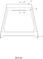
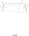
- FIG. 19 and FIG. 20 An oven 2 according to a second embodiment of the present invention is illustrated in FIG. 19 and FIG. 20 and further includes two supporting structures 40 disposed on an inside of the top cover 34 based on the first embodiment, wherein each of the two supporting structures 40 is located one of two opposite sides of the inside of the top cover 34.
- the top cover 34 fits around the top of each of the two first plates 28, the top of each of the two first plates 28 is inserted into a positioning groove 402 of one of the two supporting structures 40, so that each of the supporting structures 40 abuts the top of one of the two first plates 28.
- each of the first plates 28 is supported by one of the supporting structures 40, and a bottom of each of the first plate 28 is supported by one of the blocking portions 144 of the base 12, so that a strength of each of the first plates 28 could be increased.
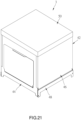
- FIG. 21 An oven 3 according to a third embodiment of the present invention is illustrated in FIG. 21 and has almost the same structure as that of the first embodiment, except that each of the first plates 44 and each of the second plates 46 of the casing 42 is a rectangular plate.
- a folded state of the casing 42 is the same as that of the first embodiment, i.e., the two first plates 44 are stacked on the bottom of the base 48, and the two second plates 46 are stacked on the top of the base 48, and therefore the folded state of the casing 42 is not repeated here.
- each of the first plates 44 stands straight to abut against one of the blocking portions 144 of the base 48 for positioning, but not limited thereto.
- each of the first plates 44 could be positioned through magnetic attraction or being stuck.
- the two supporting structures 40 of the second embodiment could be disposed in the inside of the top cover 50 of the casing 42 of the third embodiment to respectively support the top of one of the two first plates 44
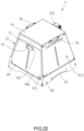
- FIG. 22 to FIG. 29 An oven 4 according to a fourth embodiment of the present invention is illustrated in FIG. 22 to FIG. 29 and has almost the same structure as that of the first embodiment, except that:
- a gas connector 542 is disposed on a rear side of the top cover 54 of the casing 52 and is connected between the heater and a gas source.
- Two anti-scald handles 56 are respectively connected to two sides of the top cover 54.
- the two anti-scald handles 56 could be made of thermal insulation materials, for example wood or Bakelite.
- the top cover 54 could be held through the two anti-scald handles 56.
- two grip pads 62 are respectively disposed on two sides of the base 60, wherein a thickness of each of the two grip pads 62 is greater than a thickness of plates located on the two sides of the base 60, so that a user could move the casing 52 more comfortably.
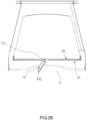
- An inside of the top cover 54 has at least two locking members 58 that are elastic. At least two of the top of the two first plates 64 and the top of the two second plates 66 have at least one locking hole 642a, 666.
- the at least two locking members 58 includes four locking members 58 respectively located at a position close to one of four corners of the top cover 54.
- Two sides of each of the first plates 64 respectively have a folded edge 642, wherein a top of each of the folded edges 642 has a locking hole 642a forming an open side on an edge of the corresponding folded edge 642.
- Two sides of each of the second plates 66 respectively have a locking hole 666 located at a position on the corresponding second plate 66 close to one of the folded edges 662.
- first outer surface 64a of each of the first plates 64 respectively have a recess 64b.
- An inside of each of the folded edges 666 of each of the second plates 66 has a protrusion 664. Both the recesses 64b and the protrusions 664 are formed by stamping.
- each of the protrusions 664 enters one of the recesses 64b for positioning by the protrusions matching with the recesses, so that each of the first plates 64 and each of the second plates 66 could not be easily moved due to an external force.
- the second plate 66 shown in FIG. 27 is partially removed for illustrating the locking hole 642a.
- Each of the locking holes 642a of the folded edges 642 of each of the first plates 64 corresponds to one of the locking holes 666 of one of the second plates 66.
- each of the locking members 58 could form a supporting structure, wherein each of the locking holes 642a of the folded edges 642 of each of the first plates 64 could abut against a side edge of one of the locking members 58. In this way, when each of the first plates 64 is pressed due to an external force, a hole edge of each of the locking holes 642a could abut against the side edge of one of the locking members 58, thereby increasing a strength of each of the first plates 64.
- each of the locking member 58 is pressed and the top cover 54 is lifted, so that the top cover 54 could be removed.
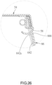
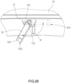
- the door 68 has a handle 70.
- the handle 70 is disposed on an outer surface 68a of the door 68 through a pivot support 72, wherein the handle 70 could be made of thermal insulation materials, for example wood or Bakelite.
- the pivot support 72 has a pivot 722 and a blocking rod 724.
- the handle 70 is pivotally connected to the pivot 722.
- the blocking rod 724 is located on a side of the pivot 722.
- the handle 70 is pivotable between a first position P41 and a second position P42. When the handle 70 is located at the first position P41, a free end 702 of the handle 70 is close to the door 68.
- the pivot degree ⁇ of the handle 70 between the first position P41 and the second position P42 is greater than 90°, preferably ranging between 110° and 130°. In the current embodiment, the pivot degree ⁇ substantially is 120°.
- the handle 70 could be pulled to pivot the door 68.
- the free end 702 of the handle 70 abuts against a loading surface F.
- the handle 70 forms a support of the door 68, so that the loading capacity of the door 68 is increased, thereby allowing a user to temporarily place objects, such as food, cooking utensils, or oven rack, on the opened door 68.
Landscapes
- Engineering & Computer Science (AREA)
- Chemical & Material Sciences (AREA)
- Combustion & Propulsion (AREA)
- Mechanical Engineering (AREA)
- General Engineering & Computer Science (AREA)
- Baking, Grill, Roasting (AREA)
Priority Applications (1)
| Application Number | Priority Date | Filing Date | Title |
|---|---|---|---|
| EP23177894.5A EP4474709A1 (de) | 2023-06-07 | 2023-06-07 | Ofengehäuse |
Applications Claiming Priority (1)
| Application Number | Priority Date | Filing Date | Title |
|---|---|---|---|
| EP23177894.5A EP4474709A1 (de) | 2023-06-07 | 2023-06-07 | Ofengehäuse |
Publications (1)
| Publication Number | Publication Date |
|---|---|
| EP4474709A1 true EP4474709A1 (de) | 2024-12-11 |
Family
ID=86732104
Family Applications (1)
| Application Number | Title | Priority Date | Filing Date |
|---|---|---|---|
| EP23177894.5A Pending EP4474709A1 (de) | 2023-06-07 | 2023-06-07 | Ofengehäuse |
Country Status (1)
| Country | Link |
|---|---|
| EP (1) | EP4474709A1 (de) |
Citations (4)
| Publication number | Priority date | Publication date | Assignee | Title |
|---|---|---|---|---|
| EP0109144A2 (de) * | 1982-11-12 | 1984-05-23 | Pyromid Inc. | Veränderbares Kochgerät |
| US4508094A (en) * | 1982-11-12 | 1985-04-02 | Pyromid, Inc. | Convertible cooking unit |
| US4545359A (en) * | 1983-02-09 | 1985-10-08 | Pyromid, Inc. | Outdoor stove |
| US6823858B1 (en) * | 2003-05-29 | 2004-11-30 | Gao-Shan Chen | Foldable conduction oven (IV) |
-
2023
- 2023-06-07 EP EP23177894.5A patent/EP4474709A1/de active Pending
Patent Citations (4)
| Publication number | Priority date | Publication date | Assignee | Title |
|---|---|---|---|---|
| EP0109144A2 (de) * | 1982-11-12 | 1984-05-23 | Pyromid Inc. | Veränderbares Kochgerät |
| US4508094A (en) * | 1982-11-12 | 1985-04-02 | Pyromid, Inc. | Convertible cooking unit |
| US4545359A (en) * | 1983-02-09 | 1985-10-08 | Pyromid, Inc. | Outdoor stove |
| US6823858B1 (en) * | 2003-05-29 | 2004-11-30 | Gao-Shan Chen | Foldable conduction oven (IV) |
Similar Documents
| Publication | Publication Date | Title |
|---|---|---|
| EP2613114B1 (de) | Kühlschrank mit Lagerbehälter | |
| US11330936B2 (en) | Covering member for an opening of a cooking cavity of a mini-oven | |
| US20140246418A1 (en) | Toaster Oven with Improved Access to Cooking Cavity | |
| EP4474709A1 (de) | Ofengehäuse | |
| EP4474708A1 (de) | Ofengehäuse | |
| US20240407598A1 (en) | Casing of oven | |
| TWM647067U (zh) | 烤箱之箱體 | |
| CN220158105U (zh) | 烤箱的箱体 | |
| TWI840166B (zh) | 烤箱之箱體 | |
| CN220236670U (zh) | 烤箱的箱体 | |
| TWI840165B (zh) | 烤箱之箱體 | |
| TWM647700U (zh) | 烤箱之箱體 | |
| US9476597B1 (en) | Adjustable oven | |
| CN220459209U (zh) | 一种便于收纳的空气炸锅 | |
| US20220372803A1 (en) | Oven | |
| CN223695549U (zh) | 锅具和烹饪器具 | |
| JP2025162909A (ja) | ホットプレート | |
| GB2179439A (en) | Heating appliance door | |
| CN222055180U (zh) | 烹饪设备 | |
| CN220793200U (zh) | 具备储物空间的集成灶 | |
| CN223773512U (zh) | 烹饪器具 | |
| JP2016153708A (ja) | オーブン装置 | |
| CN218832581U (zh) | 便携式烧烤炉 | |
| CN211673757U (zh) | 烹饪器具 | |
| CN217309951U (zh) | 一种烤盘和带有此烤盘的空气炸锅 |
Legal Events
| Date | Code | Title | Description |
|---|---|---|---|
| PUAI | Public reference made under article 153(3) epc to a published international application that has entered the european phase |
Free format text: ORIGINAL CODE: 0009012 |
|
| STAA | Information on the status of an ep patent application or granted ep patent |
Free format text: STATUS: REQUEST FOR EXAMINATION WAS MADE |
|
| 17P | Request for examination filed |
Effective date: 20240708 |
|
| AK | Designated contracting states |
Kind code of ref document: A1 Designated state(s): AL AT BE BG CH CY CZ DE DK EE ES FI FR GB GR HR HU IE IS IT LI LT LU LV MC ME MK MT NL NO PL PT RO RS SE SI SK SM TR |