EP4474700A1 - Power supply device - Google Patents
Power supply device Download PDFInfo
- Publication number
- EP4474700A1 EP4474700A1 EP24178270.5A EP24178270A EP4474700A1 EP 4474700 A1 EP4474700 A1 EP 4474700A1 EP 24178270 A EP24178270 A EP 24178270A EP 4474700 A1 EP4474700 A1 EP 4474700A1
- Authority
- EP
- European Patent Office
- Prior art keywords
- fan
- chassis
- connector
- control board
- disposed
- Prior art date
- Legal status (The legal status is an assumption and is not a legal conclusion. Google has not performed a legal analysis and makes no representation as to the accuracy of the status listed.)
- Granted
Links
Images





Classifications
-
- F—MECHANICAL ENGINEERING; LIGHTING; HEATING; WEAPONS; BLASTING
- F21—LIGHTING
- F21V—FUNCTIONAL FEATURES OR DETAILS OF LIGHTING DEVICES OR SYSTEMS THEREOF; STRUCTURAL COMBINATIONS OF LIGHTING DEVICES WITH OTHER ARTICLES, NOT OTHERWISE PROVIDED FOR
- F21V33/00—Structural combinations of lighting devices with other articles, not otherwise provided for
- F21V33/0088—Ventilating systems
- F21V33/0096—Fans, e.g. ceiling fans
-
- H—ELECTRICITY
- H05—ELECTRIC TECHNIQUES NOT OTHERWISE PROVIDED FOR
- H05K—PRINTED CIRCUITS; CASINGS OR CONSTRUCTIONAL DETAILS OF ELECTRIC APPARATUS; MANUFACTURE OF ASSEMBLAGES OF ELECTRICAL COMPONENTS
- H05K7/00—Constructional details common to different types of electric apparatus
- H05K7/20—Modifications to facilitate cooling, ventilating, or heating
- H05K7/2089—Modifications to facilitate cooling, ventilating, or heating for power electronics, e.g. for inverters for controlling motor
- H05K7/20909—Forced ventilation, e.g. on heat dissipaters coupled to components
-
- G—PHYSICS
- G06—COMPUTING OR CALCULATING; COUNTING
- G06F—ELECTRIC DIGITAL DATA PROCESSING
- G06F1/00—Details not covered by groups G06F3/00 - G06F13/00 and G06F21/00
- G06F1/16—Constructional details or arrangements
- G06F1/18—Packaging or power distribution
- G06F1/183—Internal mounting support structures, e.g. for supporting printed circuit boards
- G06F1/188—Mounting of power supply units
-
- G—PHYSICS
- G06—COMPUTING OR CALCULATING; COUNTING
- G06F—ELECTRIC DIGITAL DATA PROCESSING
- G06F1/00—Details not covered by groups G06F3/00 - G06F13/00 and G06F21/00
- G06F1/16—Constructional details or arrangements
- G06F1/18—Packaging or power distribution
- G06F1/189—Power distribution
-
- G—PHYSICS
- G06—COMPUTING OR CALCULATING; COUNTING
- G06F—ELECTRIC DIGITAL DATA PROCESSING
- G06F1/00—Details not covered by groups G06F3/00 - G06F13/00 and G06F21/00
- G06F1/16—Constructional details or arrangements
- G06F1/20—Cooling means
-
- H—ELECTRICITY
- H05—ELECTRIC TECHNIQUES NOT OTHERWISE PROVIDED FOR
- H05K—PRINTED CIRCUITS; CASINGS OR CONSTRUCTIONAL DETAILS OF ELECTRIC APPARATUS; MANUFACTURE OF ASSEMBLAGES OF ELECTRICAL COMPONENTS
- H05K7/00—Constructional details common to different types of electric apparatus
- H05K7/20—Modifications to facilitate cooling, ventilating, or heating
- H05K7/20009—Modifications to facilitate cooling, ventilating, or heating using a gaseous coolant in electronic enclosures
- H05K7/20136—Forced ventilation, e.g. by fans
- H05K7/20172—Fan mounting or fan specifications
Definitions
- the technical field relates to a power supply device, and more particularly relates to a power supply device for easy assembly.
- Fans are commonly employed in various electronic devices to facilitate cooling.
- power supply devices often utilize fans to dissipate heat to ensure that the internal components of the power supply device operate within a suitable temperature range for normal functionality.
- a typical method of fan connection involves extending a wire directly from inside the fan and attaching a connector to its conductive end. This connector is then used to establish electrical connection with the control board of the power supply device to control the operation of fan and supply necessary power.
- fans need to be designed with wire lengths and exit positions corresponding to the location of the circuit board. Therefore, even fans of the same size may not be interchangeable among different power supply devices due to differences in wire length and exit position. For example, if the fan wire is too long or the exit location is not optimal, it may interfere with other electronic components and result in wiring and assembly difficulties. If the fan wire is too short, the fan may fail to establish electrical connection with the control board and may not function.
- This disclosure provides a power supply device for simplifying the connection structure of the fan modules and increasing the convenience of use.
- This disclosure is a power supply device including a chassis, a control board, an input connector, an output connector, a fan module, a flexible printed circuit board and a light-guiding handle.
- the control board is disposed within the chassis.
- the input connector and the output connector are disposed within the chassis and electrically connected to the control board.
- the fan module is mounted within the chassis.
- the fan module includes a fan frame and a fan connector disposed on an outer surface of the fan frame.
- the flexible printed circuit board includes a conducting section, a fan connecting section and a lighting connecting section. One end of the conducting section is electrically connected to the control board, and another end of the conducting section is electrically connected to the fan connecting section and the lighting connecting section.
- the fan connecting section is electrically connected to the fan connector.
- the light-guiding handle is coupled to the chassis.
- the lighting component is disposed on the lighting connecting section and faces the light-guiding handle.
- the power supply device further includes a fan circuit board, wherein an insertion slot communicating with the hollow slot is defined on the fan frame, and the fan circuit board is inserted in the insertion slot.
- one end of the conducting section is pressed (sandwiched) between the control board and the chassis.
- the light-guiding handle and the lighting component are mounted on the fan frame.
- the fan module and the input connector are mounted on the front end of the chassis away from the output connector, and the fan connector is disposed between the fan frame and the input connector.
- control board and fan module in this disclosure are installed within the chassis, and the fan connector is disposed on the outer surface of the fan frame of the fan module.
- the fan module is electrically connected to the control board through one end of the connecting component inserting to the fan connector and another end of the connecting component inserting to the control board, thereby simplifying the connection structure between the electronic device and the fan.
- the connecting component may include a flexible printed circuit board that may be pressed between the control board and the chassis to prevent interference with other electronic components within the chassis, thereby enhancing practicality and convenience of use.
- a power supply device 1 includes a chassis 10, a control board 20, an adapter board 30, an input connector 40, an output connector 50, a fan module 60, a connecting component 70 and a light-guiding handle 80.
- the control board 20 and the adapter board 30 are arranged in the chassis 10.
- the input connector 40 and the output connector 50 are disposed within the chassis 10. In this embodiment, the input connector 40 and the output connector 50 are respectively located on the front and rear sides of the chassis 10 and electrically connected to the control board 20.
- the fan module 60 is mounted within the chassis 10 and electrically connected to the control board 20 via the connecting component 70.
- both the control board 20 and adapter board 30 are equipped with appropriate circuit components to fulfill the required functions.
- the adapter board 30 may be omitted.
- the adapter board 30 is positioned vertically and electrically connected to the control board 20.
- the control board 20 is positioned horizontally on the bottom surface of the chassis 10.
- the input connector 40 may be an IEC 60320 C14 or another suitable connector, while the output connector 50 may also adopt suitable specifications.
- the power supply device 1 is connected to the power grid to receive electrical power through the input connector 40. After conversion to the appropriate voltage by the control board 20, the power is supplied to one or more external electronic devices via the output connector 50.
- the fan module 60 includes a fan frame 61 and a fan connector 62 disposed on the outer surface of the fan frame 61.
- the fan frame 61 is used to accommodate components such as fan blades and motors.
- the fan connector 62 includes a wire-to-board connector or other suitable connectors.
- the fan module 60 further includes a fan circuit board 63 fixed on the fan frame 61.
- the fan connector 62 is positioned and electrically connected to the fan circuit board 63.
- the fan module 60 and the input connector 40 are mounted at the front end of the chassis 10 away from the output connector 50.
- the fan connector 62 is disposed on the outer surface of the fan frame 61 which is not adjacent to the chassis 10 (as shown in FIG. 1 to FIG.3 , disposed between the fan frame 61 and the input connector 40) to facilitate the assembly between the connecting component 70 and the fan connector 62.
- the fan connector 62 is disposed on the outer surface of the fan frame 61 adjacent to the chassis 10 (for example, between the fan frame 61 and the bottom surface of the chassis 10) to simplify the routing of the connecting components 70.
- the fan connector 62 may be disposed at a suitable position on the outer surface of the fan frame 61 based on different design considerations.
- the connecting component 70 is implemented in the form of a flexible printed circuit board, and includes a conducting section 71, a fan connecting section 72 and a lighting connecting section 73.
- One end of the conducting section 71 is electrically connected to the control board 20, and another end of the conducting section 71 is electrically connected to the fan connecting section 72 and the lighting connecting section 73.
- one end of the fan connecting section 72 is electrically connected to the fan connector 62.
- the fan module 60 is electrically connected to the control board 20 through the fan connecting section 72 and the conducting section 71.
- the control board 20 supplies the requisite power and/or other control functions essential for the operation of the fan module 60.
- the lighting connecting section 73 is disposed corresponding to the light-guiding handle 80 and is adjacent to the chassis 10.
- the lighting component 82 is disposed on the lighting connecting section 73 and faces the light-guiding handle 80.
- the lighting component 82 is electrically connected to the control board 20 through the lighting connecting section 73 and the conducting section 71.
- the control board 20 provides the necessary power and/or other control functions required for illuminating the lighting component 82 and makes the lighting element 82 to emit light.
- the light-guiding handle 80 is coupled to the chassis 10 for users to move the power supply device1.
- the light-guiding handle 80 may be made of a translucent material to transmit light emitted from the lighting component 82, and the light-guiding handle 80 is configured in a U shape.
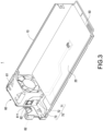
- FIG. 3 and FIG. 4 illustrate a schematic view of the connection between the flexible printed circuit board and the fan module in this disclosure and a schematic view of the combination of the fan circuit board and the fan frame in this disclosure.
- a hollow slot 611 and an insertion slot 612 communicating with the hollow slot 611 are defined on the fan frame 61.
- the fan circuit board 63 is inserted in the insertion slot 612, and that makes the fan connector 62 be exposed from the hollow slot 611.
- FIG. 5 illustrates another embodiment of the light-guiding handle in this disclosure.
- the light-guiding handle 80 is disposed on the right side in front of the chassis 10 and is not adjacent to the fan frame 61.
- the light-guiding handle 80 is mounted on the fan frame 61.
- the light-guiding handle 80 may be made of a translucent material to transmit the light emitted from the lighting component 82.
- the light-guiding handle 80 is configured in a U shape and includes a gripping section 811 and a pair of supporting sections 812 connected to the gripping section 811. Two ends of the pair of supporting sections 812 are used to be fixed on the fan frame 61 (and/or the chassis 10).
- the light-guiding handle 80 is affixed to the lighting component 82. Light emitted from the lighting component 82 may pass through the light-guiding handle 80. As a result, users may easily discern the position of the light-guiding handle 80 in areas with inadequate lighting, so as to facilitate the user to apply force on the light-guiding handle 80 to move the power supply device 1.
- a lighting hole 83 and a screw hole 84 are defined on the end surface of the supporting sections 812 of the light-guiding handle 80.
- the lighting hole 83 is arranged corresponding to the position of the lighting component 82.
- the light-guiding handle 80 is secured to the fan frame 61 (and/or the chassis 10) utilizing multiple screws inserted through the screw holes 84.
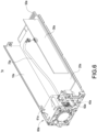
- a power supply device 1a includes a chassis 10a, a control board 20a, an adapter board 30a, an input connector 40a, an output connector 50a and a fan module 60a.
- the fan module 60a is mounted within the chassis 10a and includes a fan frame 61a and a fan connector 62a disposed on the outer surface of the fan frame 61a.
- the connecting component 70a is in the form of a conducting wire, and the fan connector 62a is electrically connected to the adapter board 30a via the connecting component 70a.
- the fan module 60, 60a includes a fan connector 62, 62a exposed from the surface of the fan frames 61, 61a. Then, the fan module 60, 60a is electrically connected to the control board 20 or the adapter board 30a through one end of the connecting component 70, 70a (such as a flexible printed circuit board or a conducting wire) electrically connected to the fan connector 62, 62a and another end of the connecting component 70, 70a electrically connected to the control board 20 or the adapter board 30a. Therefore, the power supply device 1 in this disclosure does not require specific wire lengths or exit positions corresponding to the control board 20 or the adapter board 30a to simplify the connection structure of the fan modules 60, 60a. Additionally, when the connecting component is implemented in the form of a flexible printed circuit board, the flexible printed circuit board may be pressed between the control board 20 and the chassis 10 to prevent interference with other electronic components inside the chassis 1 and increase the convenience of installation.
- the connecting component is implemented in the form of a flexible printed circuit board
- the flexible printed circuit board may be
Landscapes
- Engineering & Computer Science (AREA)
- Theoretical Computer Science (AREA)
- Physics & Mathematics (AREA)
- Microelectronics & Electronic Packaging (AREA)
- General Engineering & Computer Science (AREA)
- Human Computer Interaction (AREA)
- General Physics & Mathematics (AREA)
- Power Engineering (AREA)
- Thermal Sciences (AREA)
- Computer Hardware Design (AREA)
- Cooling Or The Like Of Electrical Apparatus (AREA)
- Arrangement Of Elements, Cooling, Sealing, Or The Like Of Lighting Devices (AREA)
Abstract
Description
- The technical field relates to a power supply device, and more particularly relates to a power supply device for easy assembly.
- Fans are commonly employed in various electronic devices to facilitate cooling. For example, power supply devices often utilize fans to dissipate heat to ensure that the internal components of the power supply device operate within a suitable temperature range for normal functionality. A typical method of fan connection involves extending a wire directly from inside the fan and attaching a connector to its conductive end. This connector is then used to establish electrical connection with the control board of the power supply device to control the operation of fan and supply necessary power.
- Additionally, because power supply devices have varying internal designs, fans need to be designed with wire lengths and exit positions corresponding to the location of the circuit board. Therefore, even fans of the same size may not be interchangeable among different power supply devices due to differences in wire length and exit position. For example, if the fan wire is too long or the exit location is not optimal, it may interfere with other electronic components and result in wiring and assembly difficulties. If the fan wire is too short, the fan may fail to establish electrical connection with the control board and may not function.
- In view of the above drawbacks, the inventor proposes this disclosure based on his expert knowledge and elaborate researches in order to solve the problems of related art.
- This disclosure provides a power supply device for simplifying the connection structure of the fan modules and increasing the convenience of use.
- This disclosure is a power supply device including a chassis, a control board, an input connector, an output connector, a fan module, a flexible printed circuit board and a light-guiding handle. The control board is disposed within the chassis. The input connector and the output connector are disposed within the chassis and electrically connected to the control board. The fan module is mounted within the chassis. The fan module includes a fan frame and a fan connector disposed on an outer surface of the fan frame. The flexible printed circuit board includes a conducting section, a fan connecting section and a lighting connecting section. One end of the conducting section is electrically connected to the control board, and another end of the conducting section is electrically connected to the fan connecting section and the lighting connecting section. The fan connecting section is electrically connected to the fan connector. The light-guiding handle is coupled to the chassis. The lighting component is disposed on the lighting connecting section and faces the light-guiding handle.
- In one embodiment, a hollow slot is defined on the fan frame, and the fan connector is exposed from the hollow slot.
- In one embodiment, the power supply device further includes a fan circuit board, wherein an insertion slot communicating with the hollow slot is defined on the fan frame, and the fan circuit board is inserted in the insertion slot.
- In one embodiment, one end of the conducting section is pressed (sandwiched) between the control board and the chassis.
- In one embodiment, the light-guiding handle and the lighting component are mounted on the fan frame.
- In one embodiment, the fan module and the input connector are mounted on the front end of the chassis away from the output connector, and the fan connector is disposed between the fan frame and the input connector.
- In comparison with the related art, the control board and fan module in this disclosure are installed within the chassis, and the fan connector is disposed on the outer surface of the fan frame of the fan module. Moreover, the fan module is electrically connected to the control board through one end of the connecting component inserting to the fan connector and another end of the connecting component inserting to the control board, thereby simplifying the connection structure between the electronic device and the fan. Additionally, the connecting component may include a flexible printed circuit board that may be pressed between the control board and the chassis to prevent interference with other electronic components within the chassis, thereby enhancing practicality and convenience of use.
- The features of the disclosure believed to be novel are set forth with particularity in the appended claims. The disclosure itself, however, may be best understood by reference to the following detailed description of the disclosure, which describes a number of exemplary embodiments of the disclosure, taken in conjunction with the accompanying drawings, in which:
-
FIG. 1 andFIG. 2 illustrate perspective schematic views of the power supply device from two sides thereof in this disclosure. -
FIG. 3 illustrates a schematic view of the connection between the flexible printed circuit board and the fan module in this disclosure. -
FIG. 4 illustrates a schematic view depicting the combination of the fan circuit board and the fan frame in this disclosure. -
FIG. 5 illustrates another embodiment of the light-guiding handle in this disclosure. -
FIG. 6 andFIG. 7 illustrate schematic views of the application of another embodiment of the power supply device in this disclosure. - The technical contents of this disclosure will become apparent with the detailed description of embodiments accompanied with the illustration of related drawings as follows. It is intended that the embodiments and drawings disclosed herein are to be considered illustrative rather than restrictive.
- Please refer to
FIG. 1 andFIG. 2 , which depict perspective schematic views of the power supply device from two sides thereof in this disclosure. Apower supply device 1 includes achassis 10, acontrol board 20, anadapter board 30, aninput connector 40, anoutput connector 50, afan module 60, a connectingcomponent 70 and a light-guidinghandle 80. Thecontrol board 20 and theadapter board 30 are arranged in thechassis 10. Theinput connector 40 and theoutput connector 50 are disposed within thechassis 10. In this embodiment, theinput connector 40 and theoutput connector 50 are respectively located on the front and rear sides of thechassis 10 and electrically connected to thecontrol board 20. Thefan module 60 is mounted within thechassis 10 and electrically connected to thecontrol board 20 via the connectingcomponent 70. - In this embodiment, both the
control board 20 andadapter board 30 are equipped with appropriate circuit components to fulfill the required functions. In some embodiments, theadapter board 30 may be omitted. Theadapter board 30 is positioned vertically and electrically connected to thecontrol board 20. Thecontrol board 20 is positioned horizontally on the bottom surface of thechassis 10. Theinput connector 40 may be an IEC 60320 C14 or another suitable connector, while theoutput connector 50 may also adopt suitable specifications. For example, thepower supply device 1 is connected to the power grid to receive electrical power through theinput connector 40. After conversion to the appropriate voltage by thecontrol board 20, the power is supplied to one or more external electronic devices via theoutput connector 50. - Please also refer to
FIG. 3 andFIG. 4 , which illustrate a schematic view of the connection between the flexible printed circuit board and the fan module in this disclosure, and a schematic view depicting the combination of the fan circuit board and the fan frame in this disclosure. Thefan module 60 includes afan frame 61 and afan connector 62 disposed on the outer surface of thefan frame 61. Thefan frame 61 is used to accommodate components such as fan blades and motors. Thefan connector 62 includes a wire-to-board connector or other suitable connectors. Additionally, thefan module 60 further includes afan circuit board 63 fixed on thefan frame 61. Thefan connector 62 is positioned and electrically connected to thefan circuit board 63. - In this embodiment, the
fan module 60 and theinput connector 40 are mounted at the front end of thechassis 10 away from theoutput connector 50. In this embodiment, thefan connector 62 is disposed on the outer surface of thefan frame 61 which is not adjacent to the chassis 10 (as shown inFIG. 1 to FIG.3 , disposed between thefan frame 61 and the input connector 40) to facilitate the assembly between the connectingcomponent 70 and thefan connector 62. In another embodiment, thefan connector 62 is disposed on the outer surface of thefan frame 61 adjacent to the chassis 10 (for example, between thefan frame 61 and the bottom surface of the chassis 10) to simplify the routing of theconnecting components 70. In other embodiments, thefan connector 62 may be disposed at a suitable position on the outer surface of thefan frame 61 based on different design considerations. - In this embodiment, the connecting
component 70 is implemented in the form of a flexible printed circuit board, and includes a conductingsection 71, afan connecting section 72 and alighting connecting section 73. One end of the conductingsection 71 is electrically connected to thecontrol board 20, and another end of the conductingsection 71 is electrically connected to thefan connecting section 72 and thelighting connecting section 73. Additionally, one end of thefan connecting section 72 is electrically connected to thefan connector 62. Thefan module 60 is electrically connected to thecontrol board 20 through thefan connecting section 72 and the conductingsection 71. - Accordingly, the
control board 20 supplies the requisite power and/or other control functions essential for the operation of thefan module 60. In this embodiment, thelighting connecting section 73 is disposed corresponding to the light-guidinghandle 80 and is adjacent to thechassis 10. Thelighting component 82 is disposed on thelighting connecting section 73 and faces the light-guidinghandle 80. Thelighting component 82 is electrically connected to thecontrol board 20 through thelighting connecting section 73 and the conductingsection 71. Thus, thecontrol board 20 provides the necessary power and/or other control functions required for illuminating thelighting component 82 and makes thelighting element 82 to emit light. - The light-guiding
handle 80 is coupled to thechassis 10 for users to move the power supply device1. In this embodiment, the light-guidinghandle 80 may be made of a translucent material to transmit light emitted from thelighting component 82, and the light-guidinghandle 80 is configured in a U shape. - Please refer to
FIG. 3 andFIG. 4 , which illustrate a schematic view of the connection between the flexible printed circuit board and the fan module in this disclosure and a schematic view of the combination of the fan circuit board and the fan frame in this disclosure. In this embodiment, ahollow slot 611 and aninsertion slot 612 communicating with thehollow slot 611 are defined on thefan frame 61. Moreover, thefan circuit board 63 is inserted in theinsertion slot 612, and that makes thefan connector 62 be exposed from thehollow slot 611. - Please further refer to
FIG. 5 , which illustrates another embodiment of the light-guiding handle in this disclosure. In the embodiment ofFIG. 1 , the light-guidinghandle 80 is disposed on the right side in front of thechassis 10 and is not adjacent to thefan frame 61. However, inFIG. 5 , the light-guidinghandle 80 is mounted on thefan frame 61. In this embodiment, the light-guidinghandle 80 may be made of a translucent material to transmit the light emitted from thelighting component 82. The light-guidinghandle 80 is configured in a U shape and includes agripping section 811 and a pair of supportingsections 812 connected to thegripping section 811. Two ends of the pair of supportingsections 812 are used to be fixed on the fan frame 61 (and/or the chassis 10). - Specifically, the light-guiding
handle 80 is affixed to thelighting component 82. Light emitted from thelighting component 82 may pass through the light-guidinghandle 80. As a result, users may easily discern the position of the light-guidinghandle 80 in areas with inadequate lighting, so as to facilitate the user to apply force on the light-guidinghandle 80 to move thepower supply device 1. - Furthermore, a
lighting hole 83 and ascrew hole 84 are defined on the end surface of the supportingsections 812 of the light-guidinghandle 80. Thelighting hole 83 is arranged corresponding to the position of thelighting component 82. Additionally, the light-guidinghandle 80 is secured to the fan frame 61 (and/or the chassis 10) utilizing multiple screws inserted through the screw holes 84. - Please further refer to
FIG. 6 andFIG. 7 , which illustrate schematic views of the application of another embodiment of the power supply device in this disclosure. Apower supply device 1a includes achassis 10a, acontrol board 20a, anadapter board 30a, aninput connector 40a, anoutput connector 50a and afan module 60a. Thefan module 60a is mounted within thechassis 10a and includes afan frame 61a and afan connector 62a disposed on the outer surface of thefan frame 61a. In this embodiment, the connectingcomponent 70a is in the form of a conducting wire, and thefan connector 62a is electrically connected to theadapter board 30a via the connectingcomponent 70a. - In summary, the
fan module fan connector fan module control board 20 or theadapter board 30a through one end of the connectingcomponent fan connector component control board 20 or theadapter board 30a. Therefore, thepower supply device 1 in this disclosure does not require specific wire lengths or exit positions corresponding to thecontrol board 20 or theadapter board 30a to simplify the connection structure of thefan modules control board 20 and thechassis 10 to prevent interference with other electronic components inside thechassis 1 and increase the convenience of installation.
Claims (6)
- A power supply device (1), comprising:a chassis (10);a control board (20), disposed in the chassis (10);an input connector (40), disposed in the chassis (10) and electrically connected to the control board (20);an output connector (50), disposed in the chassis (10) and electrically connected to the control board (20);a fan module (60), disposed in the chassis (10), comprising a fan frame (61) and a fan connector (62) disposed on an outer surface thereof;a flexible printed circuit board (70), comprising a conducting section (71), a fan connecting section (72) and a lighting connecting section (73), one end of the conducting section (71) electrically connected to the control board (20), another end of the conducting section (71) electrically connected to the fan connecting section (72) and the lighting connecting section (73), and the fan connecting section (72) electrically connected to the fan connector (62);a light-guiding handle (80), coupled to the chassis (10); anda lighting component (82), disposed on the lighting connecting section (73) and facing the light-guiding handle (80).
- The power supply device (1) according to claim 1, wherein a hollow slot (611) is defined on the fan frame (61), and the fan connector (62) is exposed from the hollow slot (611).
- The power supply device (1) according to claim 2, further comprising a fan circuit board (63), wherein an insertion slot (612) is defined on the fan frame (61) and communicates with the hollow slot (611), and the fan circuit board (63) is inserted in the insertion slot (612).
- The power supply device (1) according to claim 1, wherein one end of the conducting section (71) is sandwiched between the control board (20) and the chassis (10).
- The power supply device (1) according to claim 1, wherein the light-guiding handle (80) and the lighting component (82) are mounted on the fan frame (61).
- The power supply device (1) according to claim 1, wherein the fan module (60) and the input connector (40) are mounted on a front end of the chassis (10) away from the output connector (50), and the fan connector (62) is disposed between the fan frame (61) and the input connector (40).
Applications Claiming Priority (2)
| Application Number | Priority Date | Filing Date | Title |
|---|---|---|---|
| CN202310660362.2A CN119093518A (en) | 2023-06-06 | 2023-06-06 | Power supply device for anti-vibration fan stand with luminous handle |
| CN202410286610.6A CN119095295A (en) | 2023-06-06 | 2024-03-13 | Power supply device |
Publications (3)
| Publication Number | Publication Date |
|---|---|
| EP4474700A1 true EP4474700A1 (en) | 2024-12-11 |
| EP4474700B1 EP4474700B1 (en) | 2025-08-13 |
| EP4474700C0 EP4474700C0 (en) | 2025-08-13 |
Family
ID=91184827
Family Applications (1)
| Application Number | Title | Priority Date | Filing Date |
|---|---|---|---|
| EP24178270.5A Active EP4474700B1 (en) | 2023-06-06 | 2024-05-27 | Power supply device in combination with a vibration resistant fan module and an illuminated handle |
Country Status (3)
| Country | Link |
|---|---|
| US (1) | US20240414896A1 (en) |
| EP (1) | EP4474700B1 (en) |
| PL (1) | PL4474700T3 (en) |
Families Citing this family (2)
| Publication number | Priority date | Publication date | Assignee | Title |
|---|---|---|---|---|
| WO2023058442A1 (en) * | 2021-10-07 | 2023-04-13 | 日立Astemo株式会社 | Electronic control device |
| US20240329701A1 (en) * | 2023-03-27 | 2024-10-03 | Evga Corporation | Communication system for display card and power supply |
Citations (7)
| Publication number | Priority date | Publication date | Assignee | Title |
|---|---|---|---|---|
| US20130202429A1 (en) * | 2012-02-07 | 2013-08-08 | Aic Inc. | Combining assembly for fan fixing base |
| EP3310143A1 (en) * | 2016-10-11 | 2018-04-18 | Quanta Computer Inc. | Computer device and hot swappable fan module thereof |
| US20190182982A1 (en) * | 2017-12-07 | 2019-06-13 | Seagate Technology Llc | Low profile fan assemblies |
| US20190317577A1 (en) * | 2018-04-13 | 2019-10-17 | Cooler Master Technology Inc. | Heat dissipating device having colored lighting and persistence effect |
| US20200303883A1 (en) * | 2019-03-21 | 2020-09-24 | Delta Electronics (Shanghai) Co., Ltd. | Power supply structure |
| US20200341188A1 (en) * | 2019-04-23 | 2020-10-29 | Lumileds Holding B.V. | Flexible printed wiring structure for led light engine |
| CN212515613U (en) * | 2020-07-28 | 2021-02-09 | 苏州浪潮智能科技有限公司 | Fan module |
-
2024
- 2024-05-21 US US18/669,538 patent/US20240414896A1/en active Pending
- 2024-05-27 EP EP24178270.5A patent/EP4474700B1/en active Active
- 2024-05-27 PL PL24178270.5T patent/PL4474700T3/en unknown
Patent Citations (7)
| Publication number | Priority date | Publication date | Assignee | Title |
|---|---|---|---|---|
| US20130202429A1 (en) * | 2012-02-07 | 2013-08-08 | Aic Inc. | Combining assembly for fan fixing base |
| EP3310143A1 (en) * | 2016-10-11 | 2018-04-18 | Quanta Computer Inc. | Computer device and hot swappable fan module thereof |
| US20190182982A1 (en) * | 2017-12-07 | 2019-06-13 | Seagate Technology Llc | Low profile fan assemblies |
| US20190317577A1 (en) * | 2018-04-13 | 2019-10-17 | Cooler Master Technology Inc. | Heat dissipating device having colored lighting and persistence effect |
| US20200303883A1 (en) * | 2019-03-21 | 2020-09-24 | Delta Electronics (Shanghai) Co., Ltd. | Power supply structure |
| US20200341188A1 (en) * | 2019-04-23 | 2020-10-29 | Lumileds Holding B.V. | Flexible printed wiring structure for led light engine |
| CN212515613U (en) * | 2020-07-28 | 2021-02-09 | 苏州浪潮智能科技有限公司 | Fan module |
Also Published As
| Publication number | Publication date |
|---|---|
| US20240414896A1 (en) | 2024-12-12 |
| EP4474700B1 (en) | 2025-08-13 |
| PL4474700T3 (en) | 2025-10-20 |
| EP4474700C0 (en) | 2025-08-13 |
Similar Documents
| Publication | Publication Date | Title |
|---|---|---|
| EP4474700B1 (en) | Power supply device in combination with a vibration resistant fan module and an illuminated handle | |
| CN101960204B (en) | Integrated LED driver for LED socket | |
| US7317617B2 (en) | Temperature control of heat-generating devices | |
| WO2006126645A1 (en) | Socket for electronic part | |
| JP2007533135A (en) | Flexible high performance LED lighting system | |
| TWI874163B (en) | Power supply device | |
| US5569981A (en) | Ballast device for compact fluorescent lamp | |
| EP0079805A2 (en) | Communication equipment housing | |
| EP4475641B1 (en) | Power supply device with illuminated handle | |
| CN208113073U (en) | Electronic circuit cell and electrical equipment | |
| CN115218165B (en) | Power connection structure of LED wire groove lamp | |
| HU215612B (en) | Printed circuit board with connector assembly for electrical connecting it to electric wires of an independent electric unit | |
| CN119095295A (en) | Power supply device | |
| ITTO20030777A1 (en) | CONTROL UNIT PARTICULARLY FOR MOTOR VEHICLES | |
| CN221962009U (en) | PCB circuit board with power supply unit | |
| GB2344379B (en) | Electric fan and electrical connector | |
| JP2001135130A (en) | Downlight | |
| CN114650702A (en) | Array type connecting structure and electronic equipment | |
| CN210861583U (en) | IPM module mounting structure and air conditioner | |
| EP0094823A2 (en) | A DC power supply unit | |
| US20020193002A1 (en) | Connector structure for power supply apparatus | |
| US20220228733A1 (en) | Driver for driving a light engine of a luminaire | |
| KR100503316B1 (en) | Connector module for earth of a vehicle | |
| KR20090004165U (en) | Lighting LED Module | |
| KR20000015313U (en) | Self of communication device |
Legal Events
| Date | Code | Title | Description |
|---|---|---|---|
| PUAI | Public reference made under article 153(3) epc to a published international application that has entered the european phase |
Free format text: ORIGINAL CODE: 0009012 |
|
| STAA | Information on the status of an ep patent application or granted ep patent |
Free format text: STATUS: REQUEST FOR EXAMINATION WAS MADE |
|
| 17P | Request for examination filed |
Effective date: 20240915 |
|
| AK | Designated contracting states |
Kind code of ref document: A1 Designated state(s): AL AT BE BG CH CY CZ DE DK EE ES FI FR GB GR HR HU IE IS IT LI LT LU LV MC ME MK MT NL NO PL PT RO RS SE SI SK SM TR |
|
| GRAP | Despatch of communication of intention to grant a patent |
Free format text: ORIGINAL CODE: EPIDOSNIGR1 |
|
| STAA | Information on the status of an ep patent application or granted ep patent |
Free format text: STATUS: GRANT OF PATENT IS INTENDED |
|
| RIC1 | Information provided on ipc code assigned before grant |
Ipc: H05K 1/18 20060101ALI20250131BHEP Ipc: G06F 1/18 20060101ALI20250131BHEP Ipc: G02B 6/00 20060101ALI20250131BHEP Ipc: H05K 7/20 20060101ALI20250131BHEP Ipc: G06F 1/20 20060101ALI20250131BHEP Ipc: F21V 33/00 20060101AFI20250131BHEP |
|
| INTG | Intention to grant announced |
Effective date: 20250312 |
|
| GRAS | Grant fee paid |
Free format text: ORIGINAL CODE: EPIDOSNIGR3 |
|
| GRAA | (expected) grant |
Free format text: ORIGINAL CODE: 0009210 |
|
| STAA | Information on the status of an ep patent application or granted ep patent |
Free format text: STATUS: THE PATENT HAS BEEN GRANTED |
|
| AK | Designated contracting states |
Kind code of ref document: B1 Designated state(s): AL AT BE BG CH CY CZ DE DK EE ES FI FR GB GR HR HU IE IS IT LI LT LU LV MC ME MK MT NL NO PL PT RO RS SE SI SK SM TR |
|
| REG | Reference to a national code |
Ref country code: GB Ref legal event code: FG4D |
|
| REG | Reference to a national code |
Ref country code: CH Ref legal event code: EP |
|
| REG | Reference to a national code |
Ref country code: DE Ref legal event code: R096 Ref document number: 602024000448 Country of ref document: DE |
|
| REG | Reference to a national code |
Ref country code: IE Ref legal event code: FG4D |
|
| U01 | Request for unitary effect filed |
Effective date: 20250821 |
|
| U07 | Unitary effect registered |
Designated state(s): AT BE BG DE DK EE FI FR IT LT LU LV MT NL PT RO SE SI Effective date: 20250827 |
|
| PG25 | Lapsed in a contracting state [announced via postgrant information from national office to epo] |
Ref country code: IS Free format text: LAPSE BECAUSE OF FAILURE TO SUBMIT A TRANSLATION OF THE DESCRIPTION OR TO PAY THE FEE WITHIN THE PRESCRIBED TIME-LIMIT Effective date: 20251213 |
|
| PG25 | Lapsed in a contracting state [announced via postgrant information from national office to epo] |
Ref country code: NO Free format text: LAPSE BECAUSE OF FAILURE TO SUBMIT A TRANSLATION OF THE DESCRIPTION OR TO PAY THE FEE WITHIN THE PRESCRIBED TIME-LIMIT Effective date: 20251113 |
|
| PG25 | Lapsed in a contracting state [announced via postgrant information from national office to epo] |
Ref country code: HR Free format text: LAPSE BECAUSE OF FAILURE TO SUBMIT A TRANSLATION OF THE DESCRIPTION OR TO PAY THE FEE WITHIN THE PRESCRIBED TIME-LIMIT Effective date: 20250813 |
|
| PG25 | Lapsed in a contracting state [announced via postgrant information from national office to epo] |
Ref country code: GR Free format text: LAPSE BECAUSE OF FAILURE TO SUBMIT A TRANSLATION OF THE DESCRIPTION OR TO PAY THE FEE WITHIN THE PRESCRIBED TIME-LIMIT Effective date: 20251114 |
|
| PG25 | Lapsed in a contracting state [announced via postgrant information from national office to epo] |
Ref country code: RS Free format text: LAPSE BECAUSE OF FAILURE TO SUBMIT A TRANSLATION OF THE DESCRIPTION OR TO PAY THE FEE WITHIN THE PRESCRIBED TIME-LIMIT Effective date: 20251113 |
|
| PG25 | Lapsed in a contracting state [announced via postgrant information from national office to epo] |
Ref country code: ES Free format text: LAPSE BECAUSE OF FAILURE TO SUBMIT A TRANSLATION OF THE DESCRIPTION OR TO PAY THE FEE WITHIN THE PRESCRIBED TIME-LIMIT Effective date: 20250813 |
|
| PG25 | Lapsed in a contracting state [announced via postgrant information from national office to epo] |
Ref country code: SM Free format text: LAPSE BECAUSE OF FAILURE TO SUBMIT A TRANSLATION OF THE DESCRIPTION OR TO PAY THE FEE WITHIN THE PRESCRIBED TIME-LIMIT Effective date: 20250813 |
|
| PG25 | Lapsed in a contracting state [announced via postgrant information from national office to epo] |
Ref country code: CZ Free format text: LAPSE BECAUSE OF FAILURE TO SUBMIT A TRANSLATION OF THE DESCRIPTION OR TO PAY THE FEE WITHIN THE PRESCRIBED TIME-LIMIT Effective date: 20250813 |
|
| PG25 | Lapsed in a contracting state [announced via postgrant information from national office to epo] |
Ref country code: SK Free format text: LAPSE BECAUSE OF FAILURE TO SUBMIT A TRANSLATION OF THE DESCRIPTION OR TO PAY THE FEE WITHIN THE PRESCRIBED TIME-LIMIT Effective date: 20250813 |