EP4474648A1 - Peristaltikpumpe - Google Patents
Peristaltikpumpe Download PDFInfo
- Publication number
- EP4474648A1 EP4474648A1 EP24179558.2A EP24179558A EP4474648A1 EP 4474648 A1 EP4474648 A1 EP 4474648A1 EP 24179558 A EP24179558 A EP 24179558A EP 4474648 A1 EP4474648 A1 EP 4474648A1
- Authority
- EP
- European Patent Office
- Prior art keywords
- rotor
- peristaltic pump
- support surface
- hose segment
- pump
- Prior art date
- Legal status (The legal status is an assumption and is not a legal conclusion. Google has not performed a legal analysis and makes no representation as to the accuracy of the status listed.)
- Pending
Links
Images



Classifications
-
- F—MECHANICAL ENGINEERING; LIGHTING; HEATING; WEAPONS; BLASTING
- F04—POSITIVE - DISPLACEMENT MACHINES FOR LIQUIDS; PUMPS FOR LIQUIDS OR ELASTIC FLUIDS
- F04B—POSITIVE-DISPLACEMENT MACHINES FOR LIQUIDS; PUMPS
- F04B43/00—Machines, pumps, or pumping installations having flexible working members
- F04B43/12—Machines, pumps, or pumping installations having flexible working members having peristaltic action
- F04B43/1253—Machines, pumps, or pumping installations having flexible working members having peristaltic action by using two or more rollers as squeezing elements, the rollers moving on an arc of a circle during squeezing
-
- F—MECHANICAL ENGINEERING; LIGHTING; HEATING; WEAPONS; BLASTING
- F04—POSITIVE - DISPLACEMENT MACHINES FOR LIQUIDS; PUMPS FOR LIQUIDS OR ELASTIC FLUIDS
- F04B—POSITIVE-DISPLACEMENT MACHINES FOR LIQUIDS; PUMPS
- F04B43/00—Machines, pumps, or pumping installations having flexible working members
- F04B43/12—Machines, pumps, or pumping installations having flexible working members having peristaltic action
- F04B43/1223—Machines, pumps, or pumping installations having flexible working members having peristaltic action the actuating elements, e.g. rollers, moving in a straight line during squeezing
-
- A—HUMAN NECESSITIES
- A61—MEDICAL OR VETERINARY SCIENCE; HYGIENE
- A61M—DEVICES FOR INTRODUCING MEDIA INTO, OR ONTO, THE BODY; DEVICES FOR TRANSDUCING BODY MEDIA OR FOR TAKING MEDIA FROM THE BODY; DEVICES FOR PRODUCING OR ENDING SLEEP OR STUPOR
- A61M1/00—Suction or pumping devices for medical purposes; Devices for carrying-off, for treatment of, or for carrying-over, body-liquids; Drainage systems
- A61M1/14—Dialysis systems; Artificial kidneys; Blood oxygenators ; Reciprocating systems for treatment of body fluids, e.g. single needle systems for hemofiltration or pheresis
-
- A—HUMAN NECESSITIES
- A61—MEDICAL OR VETERINARY SCIENCE; HYGIENE
- A61M—DEVICES FOR INTRODUCING MEDIA INTO, OR ONTO, THE BODY; DEVICES FOR TRANSDUCING BODY MEDIA OR FOR TAKING MEDIA FROM THE BODY; DEVICES FOR PRODUCING OR ENDING SLEEP OR STUPOR
- A61M60/00—Blood pumps; Devices for mechanical circulatory actuation; Balloon pumps for circulatory assistance
- A61M60/10—Location thereof with respect to the patient's body
- A61M60/104—Extracorporeal pumps, i.e. the blood being pumped outside the patient's body
- A61M60/109—Extracorporeal pumps, i.e. the blood being pumped outside the patient's body incorporated within extracorporeal blood circuits or systems
- A61M60/113—Extracorporeal pumps, i.e. the blood being pumped outside the patient's body incorporated within extracorporeal blood circuits or systems in other functional devices, e.g. dialysers or heart-lung machines
-
- A—HUMAN NECESSITIES
- A61—MEDICAL OR VETERINARY SCIENCE; HYGIENE
- A61M—DEVICES FOR INTRODUCING MEDIA INTO, OR ONTO, THE BODY; DEVICES FOR TRANSDUCING BODY MEDIA OR FOR TAKING MEDIA FROM THE BODY; DEVICES FOR PRODUCING OR ENDING SLEEP OR STUPOR
- A61M60/00—Blood pumps; Devices for mechanical circulatory actuation; Balloon pumps for circulatory assistance
- A61M60/20—Type thereof
- A61M60/247—Positive displacement blood pumps
- A61M60/253—Positive displacement blood pumps including a displacement member directly acting on the blood
- A61M60/268—Positive displacement blood pumps including a displacement member directly acting on the blood the displacement member being flexible, e.g. membranes, diaphragms or bladders
- A61M60/279—Peristaltic pumps, e.g. roller pumps
-
- A—HUMAN NECESSITIES
- A61—MEDICAL OR VETERINARY SCIENCE; HYGIENE
- A61M—DEVICES FOR INTRODUCING MEDIA INTO, OR ONTO, THE BODY; DEVICES FOR TRANSDUCING BODY MEDIA OR FOR TAKING MEDIA FROM THE BODY; DEVICES FOR PRODUCING OR ENDING SLEEP OR STUPOR
- A61M60/00—Blood pumps; Devices for mechanical circulatory actuation; Balloon pumps for circulatory assistance
- A61M60/30—Medical purposes thereof other than the enhancement of the cardiac output
- A61M60/36—Medical purposes thereof other than the enhancement of the cardiac output for specific blood treatment; for specific therapy
- A61M60/37—Haemodialysis, haemofiltration or diafiltration
-
- A—HUMAN NECESSITIES
- A61—MEDICAL OR VETERINARY SCIENCE; HYGIENE
- A61M—DEVICES FOR INTRODUCING MEDIA INTO, OR ONTO, THE BODY; DEVICES FOR TRANSDUCING BODY MEDIA OR FOR TAKING MEDIA FROM THE BODY; DEVICES FOR PRODUCING OR ENDING SLEEP OR STUPOR
- A61M60/00—Blood pumps; Devices for mechanical circulatory actuation; Balloon pumps for circulatory assistance
- A61M60/80—Constructional details other than related to driving
- A61M60/845—Constructional details other than related to driving of extracorporeal blood pumps
-
- F—MECHANICAL ENGINEERING; LIGHTING; HEATING; WEAPONS; BLASTING
- F04—POSITIVE - DISPLACEMENT MACHINES FOR LIQUIDS; PUMPS FOR LIQUIDS OR ELASTIC FLUIDS
- F04B—POSITIVE-DISPLACEMENT MACHINES FOR LIQUIDS; PUMPS
- F04B43/00—Machines, pumps, or pumping installations having flexible working members
- F04B43/0009—Special features
- F04B43/0054—Special features particularities of the flexible members
- F04B43/0072—Special features particularities of the flexible members of tubular flexible members
-
- F—MECHANICAL ENGINEERING; LIGHTING; HEATING; WEAPONS; BLASTING
- F04—POSITIVE - DISPLACEMENT MACHINES FOR LIQUIDS; PUMPS FOR LIQUIDS OR ELASTIC FLUIDS
- F04B—POSITIVE-DISPLACEMENT MACHINES FOR LIQUIDS; PUMPS
- F04B43/00—Machines, pumps, or pumping installations having flexible working members
- F04B43/12—Machines, pumps, or pumping installations having flexible working members having peristaltic action
- F04B43/1253—Machines, pumps, or pumping installations having flexible working members having peristaltic action by using two or more rollers as squeezing elements, the rollers moving on an arc of a circle during squeezing
- F04B43/1276—Means for pushing the rollers against the tubular flexible member
-
- F—MECHANICAL ENGINEERING; LIGHTING; HEATING; WEAPONS; BLASTING
- F04—POSITIVE - DISPLACEMENT MACHINES FOR LIQUIDS; PUMPS FOR LIQUIDS OR ELASTIC FLUIDS
- F04B—POSITIVE-DISPLACEMENT MACHINES FOR LIQUIDS; PUMPS
- F04B53/00—Component parts, details or accessories not provided for in, or of interest apart from, groups F04B1/00 - F04B23/00 or F04B39/00 - F04B47/00
- F04B53/16—Casings; Cylinders; Cylinder liners or heads; Fluid connections
Definitions
- the invention relates to a hose roller or peristaltic pump, i.e. a positive displacement pump in which the medium to be conveyed is pressed through a hose by external mechanical deformation of the hose, according to the preamble of claim 1.
- a hose roller or peristaltic pump i.e. a positive displacement pump in which the medium to be conveyed is pressed through a hose by external mechanical deformation of the hose, according to the preamble of claim 1.
- Such pumps are often used to convey fluid, in particular blood, in a device for extracorporeal blood treatment, in particular in a dialysis machine.
- the fluid is conveyed from a low-pressure side to a high-pressure side by means of the peristaltic pump, wherein an elastically deformable fluid line in the form of a hose segment, which is referred to as a pump segment, is arranged between the low-pressure side and the high-pressure side and is deformed, in particular squeezed together, between a support surface of a pump bed and a rotor rotating relative to the latter with at least two squeezing elements.
- an elastically deformable fluid line in the form of a hose segment which is referred to as a pump segment
- a known peristaltic pump such as that shown in the document EP 1 749 549 B1 known and is, are - as in Figures 8 to 11 shown schematically - two diametrically offset squeezing elements 320 in the form of spring-mounted pressure rollers are provided on the rotor 310, and the support surface 330 is formed by a circular segment surface which extends over a sufficiently large central angle WZS greater than 180°.
- the rotor 310 carries a pair of guide projections 360, which are plate-like and extend radially to the vicinity of the support surface 330, so that the hose segment 340 is axially caught between the guide projections 360.
- An edge 370 is formed on the guide projections 360, which is used when manually unthreading the hose segment 340 as follows:
- the edges 370 formed on the guide projections 360 can only be used effectively for unthreading the hose segment 340 if the rotor 310 is in rotational positions that lie between the positions according to Figure 9 and Figure 10 In other words, the person operating the peristaltic pump has only a limited angle window FW for unthreading the hose segment (see Figure 10 ) of less than 90°, in which the probability of pinching the hose segment 340 is lower.
- the invention is therefore based on the object of developing the generic peristaltic pump in such a way that the unthreading of the hose segment accommodated in the peristaltic pump is simplified, wherein the hose segment is to be protected as far as possible from damage.
- the proposed peristaltic pump with the features of the preamble of claim 1 is characterized by a sliding edge arranged adjacent to the respective squeezing element against the direction of rotation of the rotor, extending towards the support surface, which is connected to the rotor in a rotationally fixed manner and can be gripped by the inserted hose segment. Due to the innovative arrangement of the sliding edge, the pulling movement on the hose segment during manual removal or when unthreading the hose segment causes the rotor to rotate even with very small pulling forces, which reliably prevents the hose from becoming trapped between the squeezing element and the pump bed. The pulling and friction forces exerted on the hose segment are thus reduced, which makes it possible to handle the hose segment very gently during the unthreading process.
- the sliding edge can be arranged on a wide variety of components of the peristaltic pump.
- the decisive factor is that it is located on a component that is connected to the rotor in a rotationally fixed manner, so that the force exerted on the sliding edge by the hose segment can set the rotor in rotation.
- the sliding edge is advantageously either part of a rotor body, or a rocker that is connected to the rotor in a rotationally fixed manner, or a rotor cover with a cover plate that spans the squeezing elements.
- the cover plate of the rotor cover thickens in the circumferential direction against the direction of rotation to form the sliding edge.
- the sliding edge is formed and/or coated from a material that has abrasion-minimizing sliding properties.
- a peristaltic pump is shown, such as the one used in dialysis machines.
- the peristaltic pump has the task of to pump a defined volume of a medium, such as blood or dialysis fluid, by deforming and clamping the elastically deformable fluid line.
- the peristaltic pump for pumping blood usually pumps from a negative pressure side PN (low pressure side) to a positive pressure side PP (high pressure side).
- the peristaltic pump has a pump housing 5 in which a rotor 10 rotatable about a rotor axis A is accommodated with at least two squeezing elements 20, here pressure rollers, which are diametrically offset from one another in the circumferential direction, for example, and which has a support surface 30 extending in an arc around the rotor axis A and radially spaced from the rotor 10, which is used for radially supporting a radially insertable between the rotor 10 and the support surface 30, in Figure 1 hose segment not shown.
- the squeezing elements 20 are, for example, spring-mounted on a rocker not shown in more detail, which in turn is pivotally attached to the rotor 10.
- the hose segment used in the peristaltic pump is referred to below as the pump segment.
- the Figure 1 The hose segment not shown does not rest in the pump bed marked with reference number 7, but is guided by two guide pins 70, 72 integrated into the rocker (see Figure 2 ) is held in a central position relative to the squeezing elements 20.
- the support surface 30 is generally formed by a cylindrical surface, but it can also be recessed in a trough shape.
- the direction of rotation of the rotor 10 when conveying fluid is indicated by the arrow D.
- Figure 2 shows details of the rotor 10. It has a rotor base body 42 (not shown in detail) and a rotor cover 42A.
- the rotor 10 can be removed from a drive shaft (not shown in detail) by means of a button 44 that can be operated from the side.
- the squeezing elements 20 are rotatably mounted on a rocker arm 41 that is flexibly supported on the rotor base body 42.
- the rotor cover 42A which rotates with the rotor 10, has guide surfaces 46, 48 in the area of the squeezing elements 20, of which one guide surface 46 runs in front of the squeezing element 20 and the other guide surface 48 runs in front of the
- the guide surfaces 46, 48 are therefore arranged adjacent to each other on both sides of the squeeze element 20 in the circumferential direction and are designed in such a way that - as can be seen from the Figures 3 recognizable - form with the support surface 30 a circular segment-like guide channel FK1 and FK2 in which the hose segment 40 inserted into the pump bed 7, which is also referred to as pump segment, is radially caught with a predetermined clearance fit.
- Figure 3 shows that the pump segment 40 is fixed to the pump housing 5 during operation of the peristaltic pump by means of two fitting bodies 54, 56 which can be fixed to connections 62, 64 of the pump housing 5 in a displacement-proof manner.
- the rotor cover 42 i.e. a part connected to the rotor 10 in a rotationally fixed manner, has a sliding edge 80 arranged adjacent to the respective squeezing element 20 against the direction of rotation D of the rotor 10, extending towards the support surface, which - like the Figure 3 can be removed - is gripped by the inserted hose segment, i.e. by the pump segment 40.
- the sliding edge 80 is formed and/or coated from a material that has abrasion-minimizing sliding properties
- the sliding edge 80 is located between the pressure roller, i.e. the squeezing element 20, and the guide surface 48 that follows it in the direction of rotation, i.e. in the immediate vicinity of the squeezing element 20.
- This arrangement means that the area in which the rotor 10 must be located during manual unthreading in order to avoid jamming the pump segment 40 is significantly larger than in known peristaltic pumps.
- the rotor 10 must be in a position between the Figure 4 shown position 1 and the one in Figure 5 shown position 2, which are separated from each other by the angle of rotation FW*, which is in the order of 120 to 130°. Manual unthreading by the operator is thus made considerably easier because he no longer has to pay close attention to the position of the rotor 10.
- the function of the sliding edge 80 is always fulfilled when it is formed or attached to a component of the peristaltic pump that is connected in a rotationally fixed manner to the rotor 10.
- this component is formed by the rotor cover 42, which has a cover plate 43 that overlaps the squeezing elements 20.
- the cover plate 43 for forming the sliding edge 80 in the circumferential direction against the direction of rotation D thickened, whereby the sliding edge 80 is shifted closer towards the pump bed 7.
- This thickening can be achieved, for example, by the cover plate 43 - as in Figure 2 best illustrated - has an angled edge web 45 to form the sliding edge 80. At its radially outermost end 45R, the edge web 45 merges into a peripheral edge section, the height of which gradually decreases towards the squeezing element 20.
- the sliding edge 80 can also be part of a rotor body or a rocker connected to the rotor 10 and carrying the crushing elements.
- two squeezing elements are provided, which are arranged rigidly in a relative position of 180° or at a fixed angle of 180° to one another.
- the squeezing elements can be arranged on rotor arms, which can be designed to be pivotable in the circumferential direction relative to the rotor.
- the squeezing elements do not have to be designed as squeezing rollers or pressure rollers, which advantageously roll along the fluid line in a way that protects the material. Sliding shoes that move gliding over the hose segment can also be provided.
- the invention thus creates a peristaltic pump, in particular for conveying fluid in a device for extracorporeal blood treatment, with a pump housing in which a rotor rotatable about a rotor axis is accommodated with at least two squeezing elements offset from one another in the circumferential direction and which has a support surface extending in an arc around the rotor axis and radially spaced from the rotor, which is designed to support a hose segment that can be inserted radially between the rotor and the support surface.
- the peristaltic pump has a sliding edge arranged adjacent to the respective squeezing element against the direction of rotation of the rotor, extending towards the support surface, which is connected to the rotor in a rotationally fixed manner and can be gripped under by the inserted hose segment.
Landscapes
- Health & Medical Sciences (AREA)
- Engineering & Computer Science (AREA)
- Heart & Thoracic Surgery (AREA)
- Mechanical Engineering (AREA)
- Cardiology (AREA)
- General Health & Medical Sciences (AREA)
- Veterinary Medicine (AREA)
- Hematology (AREA)
- Life Sciences & Earth Sciences (AREA)
- Animal Behavior & Ethology (AREA)
- Anesthesiology (AREA)
- Public Health (AREA)
- Biomedical Technology (AREA)
- General Engineering & Computer Science (AREA)
- Urology & Nephrology (AREA)
- Pulmonology (AREA)
- Emergency Medicine (AREA)
- Vascular Medicine (AREA)
- Reciprocating Pumps (AREA)
- External Artificial Organs (AREA)
Abstract
Description
- Die Erfindung betrifft ein eine Schlauchrollen- bzw. Peristaltikpumpe, d.h. eine Verdrängerpumpe, bei der das zu fördernde Medium durch äußere mechanische Verformung eines Schlauches durch diesen hindurchgedrückt wird, gemäß dem Oberbegriff des Patentanspruchs 1. Derartige Pumpen werden häufig zum Fördern von Fluid, insbesondere Blut, in einer Vorrichtung zur extrakorporalen Blutbehandlung, insbesondere in einer Dialysemaschine, verwendet. Das Fluid wird dabei mittels der Peristaltikpumpe von einer Niederdruckseite zu einer Hochdruckseite gefördert, wobei eine elastisch verformbare und zwischen der Niederdruckseite und der Hochdruckseite angeordnete Fluidleitung in Form eines Schlauchsegments, welches als Pumpensegment bezeichnet wird, zwischen einer Stützfläche eines Pumpenbetts und einem gegenüber dieser rotierenden Rotor mit zumindest zwei Quetschelementen verformt, insbesondere zusammengequetscht.
- Bei einer bekannten Peristaltikpumpe, wie sie beispielsweise aus dem Dokument
EP 1 749 549 B1 bekannt und ist, sind - wie inFigur 8 bis 11 schematisch dargestellt - am Rotor 310 zwei diametral zueinander versetzt angeordnete Quetschelemente 320 in Form von gefedert gelagerten Andruckrollen vorgesehen, und die Stützfläche 330 wird von einer Kreissegmentfläche gebildet, die sich über einen ausreichend großen Zentriwinkel WZS größer als 180° erstreckt. - Zur zusätzlichen Fixierung des in die Peristaltikpumpe, d.h. in das Pumpenbett eingelegten Schlauchsegments 340 (siehe
Figur 11 ), befindet sich in der Mitte zwischen den beiden Andruckrollen 320 jeweils eine kreissegmentartig ausgeführte Führungsfläche 350, die sich über einen Zentriwinkel WZF (sieheFigur 10 ) von etwa 30° erstreckt. Der Führungsfläche 350 vorlaufend trägt der Rotor 310 ein Paar von Führungsvorsprüngen 360, die plattenartig ausgebildet sind und sich radial bis in die Nähe der Stützfläche 330 erstrecken, so dass das Schlauchsegments 340 zwischen den Führungsvorsprüngen 360 axial gefangen ist. Am vorlaufenden Ende der Führungsvorsprünge 360 ist eine Kante 370 ausgebildet, die beim manuellen Ausfädeln des Schlauchsegments 340 wie folgt genutzt wird: - Wenn das Schlauchsegment 340 - wie in
Figur 11 gezeigt - aus dem Gehäuse der Peristaltikpumpe ausgefädelt werden soll, besteht bei der bekannten Peristaltikpumpe die Gefahr, dass das Schlauchsegment 340 dann, wenn der Rotor 310 eine ungünstige Drehlage einnimmt, eingeklemmt wird.Figur 11 zeigt einen solchen Zustand. Die an den Führungsvorsprüngen 360 ausgebildeten Kanten 370 können nur dann sinnvoll zum Ausfädeln des Schlauchsegment 340 genutzt werden, wenn sich der Rotor 310 in Drehlagen befindet, die zwischen den Positionen gemäßFigur 9 und Figur 10 liegen. Mit anderen Worten, der die Peristaltikpumpe bedienenden Person steht zum Ausfädeln des Schlauchsegments nur ein begrenztes Winkelfenster FW (sieheFigur 10 ) von unter 90° zur Verfügung, in dem die Wahrscheinlichkeit des Einklemmens des Schlauchsegments 340 geringer ist. - Der Erfindung liegt daher die Aufgabe zugrunde, die gattungsgemäße Peristaltikpumpe derart weiterzubilden, dass das Ausfädeln des in der Peristaltikpumpe aufgenommenen Schlauchsegments vereinfacht ist, wobei das Schlauchsegment weitestgehend vor Beschädigungen geschützt sein soll.
- Diese Aufgabe wird durch die Merkmale des Anspruchs 1 gelöst.
- Die vorgeschlagene Peristaltikpumpe mit den Merkmalen des Oberbegriffs des Anspruchs 1 zeichnet sich durch eine dem jeweiligen Quetschelement entgegen der Drehrichtung des Rotors benachbart angeordnete, sich zur Stützfläche hin erstreckende Abgleitkante aus, die an den Rotor drehfest angeschlossen und vom eingelegten Schlauchsegment untergreifbar ist. Durch die neuerungsgemäße Anordnung der Abgleitkante bewirkt die Zugbewegung am Schlauchsegments bei der manuellen Entnahme bzw. beim Ausfädeln des Schlauchsegments schon bei sehr kleinen Zugkräften ein Drehen des Rotors, wodurch ein Einklemmen des Schlauches zwischen Quetschelement und Pumpenbett zuverlässig verhindert wird. Die auf das Schlauchsegment ausgeübten Zug- und Reibungskräfte werden somit verringert, wodurch es gelingt, das Schlauchsegment beim Ausfädelvorgang sehr schonend zu behandeln. Dabei ergibt sich der zusätzliche Vorteil, dass aufgrund der Nähe der Abgleitkante zu den Quetschelementen bzw. Andruckrollen der Bereich, in dem sich der Rotor beim manuellen Ausfädeln befinden muss, um das Einklemmen des Schlauches zu vermeiden, größer wird, so dass das Ausfädeln des Schlauchsegments insgesamt vereinfacht wird.
- Die Abgleitkante kann an unterschiedlichsten Komponenten der Peristaltikpumpe angeordnet sein. Entscheidend ist, dass sie sich an einer Komponente befindet, die drehfest an den Rotor angeschlossen ist, so dass die auf die Abgleitkante vom Schlauchsegment ausgeübte Kraft den Rotor in Drehbewegung versetzen kann. Vorteilhafterweise ist die Abgleitkante entweder Bestandteil eines Rotorkörpers, oder einer mit dem Rotor drehfest verbundenen Schwinge oder einer Rotorabdeckung mit einem die Quetschelemente übergreifenden Deckplatte.
- Je tiefer die Abgleitkante liegt, d.h. je näher die Abgleitkante dem Pumpenbett liegt, desto früher kommt das Schlauchsegment beim Ausfädeln mit ihr in Kontakt. Deshalb ist es von Vorteil, wenn sich die Deckplatte der Rotorabdeckung zur Ausbildung der Abgleitkante in Umfangsrichtung entgegen der Drehrichtung verdickt.
- Eine besonders einfach herzustellende Anordnung ergibt sich dann, wenn die Deckplatte zur Ausbildung der Abgleitkante einen nach unten abgewinkelten Randsteg aufweist.
- Vorteile hinsichtlich der Montage der Quetschelemente ergeben sich, wenn der Randsteg an seinem radial äußersten Ende in einen Umfangskantenabschnitt übergeht, dessen Höhe sich zum Quetschelement hin allmählich verringert.
- Vorzugsweise wird die Abgleitkante von einem Werkstoff gebildet und/oder beschichtet, der abriebminimierende Gleiteigenschaften hat.
- Nachstehend werden Ausführungsbeispiele der Erfindung anhand schematischer Zeichnungen näher erläutert. Es zeigen:
-
Figur 1 eine perspektivische Darstellung einer beispielhaften Ausführungsform einer Peristaltikpumpe, wie sie in Verbindung mit einer Vorrichtung zur extrakorporalen Blutbehandlung Verwendung finden kann; -
Figur 2 eine perspektivische Ansicht eines in der Peristaltikpumpe gemäßFigur 1 verwendeten Rotors; -
Figur 3 eine schematische Ansicht der Peristaltikpumpe beim Ausfädeln eines Schlauchsegments aus dem Pumpenbett; -
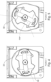
Figuren 4 und 5 Draufsichten der Peristaltikpumpe in verschiedenen Drehstellungen des Rotors, in denen ein einquetschsicheres Ausfädeln des Schlauchsegments ermöglicht ist; -
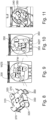
Figur 6 eine schematische Ansicht einer bekannten gattungsbildenden Peristaltikpumpe zur Verdeutlichung des Drehlagefensters für ein sicheres Ausfädeln des Schlauchsegments; -
Figur 7 eine derFigur 6 entsprechende Ansicht einer neuerungsgemäßen Ausführungsform der Peristaltikpumpe; -
Figur 8 eine perspektivische Ansicht eines Rotors einer bekannten Peristaltikpum pe; -
Figuren 9 und 10 Draufsichten einer bekannten Peristaltikpumpe in verschiedenen Drehstellungen des Rotors, in denen ein Ausfädeln des Schlauchsegments empfohlen wird; und -
Figur 11 eine schematische Ansicht der bekannten Peristaltikpumpe mit einer für das Ausfädeln ungünstigen Drehposition des Rotors. - In den
Figuren 1 bis 6 ist eine Peristaltikpumpe gezeigt, wie sie beispielsweise in Dialysemaschinen eingesetzt wird. Die Peristaltikpumpe hat dort die Aufgabe, ein definiertes Volumen eines Mediums, wie zum Beispiel Blut oder Dialysefluid, durch Verformen und Abklemmen der elastisch verformbaren Fluidleitung zu fördern. Die Peristaltikpumpe zur Förderung von Blut fördert in der Regel von einer negativen Druckseite PN (Niederdruckseite) auf eine positive Druckseite PP (Hochdruckseite). - Wie in
Figur 1 dargestellt, hat die Peristaltikpumpe ein Pumpengehäuse 5, in dem ein um eine Rotorachse A rotierbarer Rotor 10 mit zumindest zwei in Umfangsrichtung zueinander beispielsweise diametral versetzten Quetschelementen 20 , hier Druckrollen, aufgenommen ist und welches eine sich bogenförmig um die Rotorachse A erstreckende und radial von dem Rotor 10 beabstandete Stützfläche 30 aufweist, die zum radialen Abstützen eines radial zwischen den Rotor 10 und die Stützfläche 30 einbringbaren, inFigur 1 nicht gezeigten Schlauchsegments eingerichtet ist. Die Quetschelemente 20 sind beispielsweise abgefedert auf einer nicht näher bezeichneten Schwinge gelagert, die ihrerseits schwenkbeweglich am Rotor 10 befestigt ist. - Das in der Peristaltikpumpe eingesetzte Schlauchsegment wird nachfolgend als Pumpensegment bezeichnet. Bodenseitig stützt sich das in
Figur 1 nicht gezeigte Schlauchsegment nicht im mit dem Bezugszeichen 7 versehenen Pumpenbett ab, sondern wird durch zwei in die Schwinge integrierte Führungsstifte 70, 72 (sieheFigur 2 ) in mittiger Position zu den Quetschelementen 20 gehalten. Die Stützfläche 30 ist in der Regel von einer Zylinderfläche gebildet, sie kann jedoch auch muldenförmig vertieft sein. Die Drehrichtung des Rotors 10 beim Fördern von Fluid ist mit dem Pfeil D bezeichnet. -
Figur 2 zeigt Einzelheiten des Rotors 10. Er hat einen nicht näher dargestellten Rotor-Grundkörper 42 und eine Rotorabdeckung 42A. Der Rotor 10 ist durch eine seitlich bedienbare Taste 44 von einer nicht näher gezeigten Antriebswelle abnehmbar. Die Quetschelemente 20 sind drehbar auf einer gelenkig am Rotor-Grundkörper 42 federnd abgestützten Schwinge 41 gelagert. - Die sich mit dem Rotor 10 mitdrehende Rotorabdeckung 42A trägt im Bereich der Quetschelemente 20 Führungsflächen 46, 48, von denen die eine Führungsfläche 46 dem Quetschelement 20 vorläuft und die andere Führungsfläche 48 dem Quetschelement 20 nachläuft. Die Führungsflächen 46, 48 sind demnach jeweils zu beiden Seiten des Quetschelements 20 in Umfangsrichtung benachbart derart angeordnet und gestaltet, dass sie - wie aus der
Figuren 3 erkennbar - mit der Stützfläche 30 jeweils einen kreissegmentartigen Führungskanal FK1 und FK2 ausbilden, in dem das in das Pumpenbett 7 eingelegte Schlauchsegment 40, das auch als Pumpensegment bezeichnet wird, mit vorgegebener Spielpassung radial gefangen ist.Figur 3 lässt erkennen, dass das Pumpensegment 40 im Betrieb der Peristaltikpumpe am Pumpengehäuse 5 mittels zweier Passkörper 54, 56 fixiert sind, die an Anschlüssen 62, 64 des Pumpengehäuses 5 verschiebesicher fixierbar sind. - Wie der Darstellung gemäß
Figur 2 entnommen werden kann, hat die Rotorabdeckung 42, also ein an den Rotor 10 drehfest angeschlossenes Teil, eine dem jeweiligen Quetschelement 20 entgegen der Drehrichtung D des Rotors 10 benachbart angeordnete, sich zur Stützfläche hin erstreckende Abgleitkante 80, die - wie derFigur 3 entnommen werden kann - vom eingelegten Schlauchsegment, also vom Pumpensegment 40 untergriffen ist. - Wenn das Pumpensegment 40 ausgefädelt werden soll, wird - wie in
Figur 3 dargestellt - der an der Niederdruckseite PN liegende Passkörper 54 vom Pumpengehäuse 5 gelöst und vom Pumpenbett 7 nach oben gezogen. Der Rotor 10 soll dabei die inFigur 3 gezeigte Drehlage einnehmen. Weil das Pumpensegment 40 die Abgleitkante 80 untergreift, berührt das Pumpensegment 40 - wenn es wie inFigur 3 dargestellt nach oben gezogen wird - die Abgleitkante 80 in einem nach oben gebogenen Zustand, so dass die Kontaktkraft eine in Drehrichtung D des Rotors 10 gerichtete Kraftkomponente hat, die inFigur 2 mit dem Pfeil FD eingetragen ist. Wenn also das Pumpensegment 40 ausgefädelt werden soll, genügt eine kleine von Hand aufgebrachte Zugkraft, um den Rotor 10 in Richtung des Pfeils D zu drehen und das Pumpensegment 40 sukzessive freizugeben, so dass es aus dem Pumpenbett herausgezogen werden kann. Die auf das Pumpensegment 40 einwirkenden Zug- und Kontaktkräfte bleiben auf diese Weise relativ begrenzt, was der Haltbarkeit des Schlauchsegments zugutekommt. - Um das Pumpensegment 40 zusätzlich möglichst wenig zu beanspruchen, ist die Abgleitkante 80 von einem Werkstoff gebildet und/oder beschichtet, der abriebminimierende Gleiteigenschaften hat
- Die Abgleitkante 80 befindet sich im gezeigten Ausführungsbeispiel zwischen der Andruckrolle, also dem Quetschelement 20 und der diesem in Drehrichtung nachlaufenden Führungsfläche 48, also in unmittelbarer Nachbarschaft zum Quetschelement 20. Diese Anordnung führt dazu, dass der Bereich, in dem sich der Rotor 10 beim manuellen Ausfädeln befinden muss, um das Einklemmen des Pumpensegments 40 zu vermeiden, wesentlich größer als bei bekannten Peristaltikpumpen wird. Der Rotor 10 muss sich in einer Position, zwischen der in
Figur 4 gezeigten Position 1 und der inFigur 5 gezeigten Position 2 befinden, die durch den Drehwinkel FW* voneinander getrennt sind, der in der Größenordnung von 120 bis 130° liegt. Das manuelle Ausfädeln durch die Bedienperson wird dadurch erheblich einfacher, weil sie nicht mehr verstärkt auf die Position des Rotors 10 achten muss. - In den
Figuren 6 und 7 sind die Drehpositionen, zwischen denen sich der Rotor 310 beim Stand der Technik und der Rotor 10 bei der anmeldungsgemäßen Ausgestaltung zum leichten Ausfädeln des Pumpensegments 40 bzw. 340 befinden muss, gegenübergestellt. InFigur 6 ist der bekannte Rotor 310 mit beiden Grenz-Drehpositionen gezeigt, inFigur 7 der anmeldungsgemäße Rotor 10. In einer ersten Drehposition ist der Rotor mit durchgezogenen Linien dargestellt, in der zweiten Grenz-Drehlage mit gestrichelten Linien. Man erkennt, dass sich das erlaubte Winkelfenster FW mit der anmeldungsgemäßen Positionierung und Ausgestaltung der Abgleitkante 80 erheblich auf den Wert FW* erweitern lässt. - Die Funktion der Abgleitkante 80 wird immer dann erfüllt, wenn sie an einer Komponente der Peristaltikpumpe ausgebildet oder angebracht ist, die drehfest mit dem Rotor 10 verbunden ist. Im gezeigten Ausführungsbeispiel ist diese Komponente von der Rotorabdeckung 42 gebildet, die eine die Quetschelemente 20 übergreifende Deckplatte 43 hat. Aus der
Figur 2 ist ersichtlich, dass sich die Deckplatte 43 zur Ausbildung der Abgleitkante 80 in Umfangsrichtung entgegen der Drehrichtung D verdickt, wodurch die Abgleitkante 80 näher in Richtung auf das Pumpenbett 7 zu verlagert wird. Diese Verdickung kann beispielsweise dadurch realisiert werden, dass die Deckplatte 43 - wie inFigur 2 am besten dargestellt - zur Ausbildung der Abgleitkante 80 einen abgewinkelten Randsteg 45 aufweist. An seinem radial äußersten Ende 45R geht dabei der Randsteg 45 in einen Umfangskantenabschnitt über, dessen Höhe sich zum Quetschelement 20 hin allmählich verringert. - Selbstverständlich sind Abweichungen vom beschriebenen Ausführungsbeispiel möglich, ohne den Grundgedanken der Erfindung zu verlassen.
- So kann die Abgleitkante 80 auch Bestandteil eines Rotorkörpers oder einer an den Rotor 10 angebunden, die Quetschelemente tragenden Schwinge sein.
- Bei der vorstehend beschriebenen Peristaltikpumpe sind zwei Quetschelemente vorgesehen, die in einer relativen Position von 180° starr bzw. in einem festen Winkel von 180° zueinander angeordnet sind. Es kann jedoch auch vorgesehen sein, dass mehr als zwei Quetschelemente vorhanden sind und dass die Quetschelemente in Rotationsrichtung relativ zueinander winkelpositionierbar ausgebildet sind. Hierzu können die Quetschelemente auf Rotorarmen angeordnet sein, die gegenüber dem Rotor in Umfangsrichtung verschwenkbar ausgebildet sein können.
- Die Quetschelemente müssen nicht als Quetschrollen oder Andruckrollen, die in vorteilhafter Weise materialschonend an der Fluidleitung abrollen, ausgebildet sein. Es können auch Gleitschuhe, die sich gleitend über das Schlauchsegment bewegen, vorgesehen sein.
- Die Erfindung schafft somit Peristaltikpumpe, insbesondere zum Fördern von Fluid in einer Vorrichtung zur extrakorporalen Blutbehandlung, mit einem Pumpengehäuse, in dem ein um eine Rotorachse rotierbarer Rotor mit zumindest zwei in Umfangsrichtung zueinander versetzten Quetschelementen aufgenommen ist und welches eine sich bogenförmig um die Rotorachse erstreckende und radial von dem Rotor beabstandete Stützfläche aufweist, die zum Abstützen eines radial zwischen den Rotor und die Stützfläche einbringbaren Schlauchsegments eingerichtet ist. Zur Vereinfachung des manuellen Ausfädelns des Schlauchsegments, hat die Peristaltikpumpe eine dem jeweiligen Quetschelement entgegen der Drehrichtung des Rotors benachbart angeordnete, sich zur Stützfläche hin erstreckende Abgleitkante, die an den Rotor drehfest angeschlossen und vom eingelegten Schlauchsegment untergreifbar ist.
-
- A
- Rotorachse
- WZF
- Zentriwinkel der Führungsfläche
- D
- Drehrichtung
- PN
- Niederdruckseite
- PP
- Hochdruckseite
- FW, FW*
- Winkelfenster
- FD
- Kraftkomponente in Drehrichtung
- 5
- Pumpengehäuse
- 7
- Pumpenbett
- 10
- Rotor
- 20
- Quetschelement
- 30
- Stützfläche
- 40
- Pumpensegment
- 42
- Rotor-Grundkörper
- 42A
- Rotorabdeckung
- 43
- Deckplatte
- 44
- Taste
- 45
- Randsteg
- 46
- Führungsfläche
- 48
- Führungsfläche
- 54, 56
- Passkörper
- 62, 64
- Anschlüsse
- 70
- oberer Führungsstift
- 72
- unterer Führungsstift
- 80
- Abgleitkante
- 310
- Rotor
- 320
- Quetschelemente
- 330
- Stützfläche
- 340
- Pumpensegment
- 350
- Führungsfläche
- 360
- Führungsvorsprünge
- 370
- Kanten
Claims (6)
- Peristaltikpumpe, insbesondere zum Fördern von Fluid in einer Vorrichtung zur extrakorporalen Blutbehandlung, miteinem Pumpengehäuse (5), in dem ein um eine Rotorachse (A) rotierbarer Rotor (10) mit zumindest zwei in Umfangsrichtung zueinander versetzten Quetschelementen (20) aufgenommen ist und welches eine sich bogenförmig um die Rotorachse (A) erstreckende und radial von dem Rotor (10) beabstandete Stützfläche (30) aufweist, die zum Abstützen eines radial zwischen den Rotor (10) und die Stützfläche (30) einbringbaren Schlauchsegments (40) eingerichtet ist, gekennzeichnet durcheine dem jeweiligen Quetschelement (20) entgegen der Drehrichtung (D) des Rotors (10) benachbart angeordnete, sich zur Stützfläche (30) hin erstreckende Abgleitkante (80), die an den Rotor (10) drehfest angeschlossen und vom eingelegten Schlauchsegment (40) untergreifbar ist.
- Peristaltikpumpe nach Anspruch 1, dadurch gekennzeichnet, dass die Abgleitkante (80) Bestandteil eines Rotorkörpers (42), einer mit dem Rotor (10) drehfest verbundenen Schwinge oder einer Rotorabdeckung (42A) mit einem die Quetschelemente (20) übergreifenden Deckplatte (43) ist.
- Peristaltikpumpe nach Anspruch 2, dadurch gekennzeichnet, dass sich die Deckplatte (43) zur Ausbildung der Abgleitkante (80) in Umfangsrichtung entgegen der Drehrichtung (D) verdickt.
- Peristaltikpumpe nach Anspruch 3, dadurch gekennzeichnet, dass die Deckplatte (43) zur Ausbildung der Abgleitkante (80) einen abgewinkelten Randsteg (45) aufweist.
- Peristaltikpumpe nach Anspruch 4, dadurch gekennzeichnet, dass der Randsteg (45) an seinem radial äußersten Ende (45R) in einen Umfangskantenabschnitt übergeht, dessen Höhe sich zum Quetschelement (20) hin allmählich verringert.
- Peristaltikpumpe nach einem der Ansprüche 1 bis 5, dadurch gekennzeichnet, dass die Abgleitkante (80) von einem Werkstoff gebildet und/oder beschichtet ist, der abriebminimierende Gleiteigenschaften hat.
Applications Claiming Priority (1)
| Application Number | Priority Date | Filing Date | Title |
|---|---|---|---|
| DE102023115055.3A DE102023115055A1 (de) | 2023-06-07 | 2023-06-07 | Schlauchrollenpumpe |
Publications (1)
| Publication Number | Publication Date |
|---|---|
| EP4474648A1 true EP4474648A1 (de) | 2024-12-11 |
Family
ID=91375670
Family Applications (1)
| Application Number | Title | Priority Date | Filing Date |
|---|---|---|---|
| EP24179558.2A Pending EP4474648A1 (de) | 2023-06-07 | 2024-06-03 | Peristaltikpumpe |
Country Status (4)
| Country | Link |
|---|---|
| US (1) | US12560159B2 (de) |
| EP (1) | EP4474648A1 (de) |
| CN (1) | CN119103089A (de) |
| DE (1) | DE102023115055A1 (de) |
Citations (2)
| Publication number | Priority date | Publication date | Assignee | Title |
|---|---|---|---|---|
| EP1749549B1 (de) | 2005-08-02 | 2008-01-30 | Möller Medical GmbH & Co.KG | Liquor-Drainagesystem |
| DE102019133969A1 (de) * | 2019-12-11 | 2021-06-17 | Fresenius Medical Care Deutschland Gmbh | Fördervorrichtung zum Fördern von medizinischen Fluiden durch einen Schlauch |
Family Cites Families (16)
| Publication number | Priority date | Publication date | Assignee | Title |
|---|---|---|---|---|
| US3700361A (en) * | 1971-07-08 | 1972-10-24 | Sarns Inc | Peristaltic pump construction |
| DK140318B (da) * | 1973-05-29 | 1979-07-30 | Erik Bach Kyvsgaard | Slangepumpe. |
| US3963023A (en) * | 1974-11-04 | 1976-06-15 | Cobe Laboratories, Inc. | Extracorporeal blood circulation system and pump |
| US4174193A (en) * | 1976-12-16 | 1979-11-13 | Senko Medical Instrument Mfg. Co., Ltd. | Peristatic pump with hose positioning means and pressure adjustment apparatus |
| US4544329A (en) * | 1983-01-14 | 1985-10-01 | Windsor Medical, Inc. | Peristaltic pump having a spiral cam and straight peristaltic tube |
| US4558996A (en) * | 1983-06-30 | 1985-12-17 | Organon Teknika Corporation | Easy load peristaltic pump |
| US5062775A (en) * | 1989-09-29 | 1991-11-05 | Rocky Mountain Research, Inc. | Roller pump in an extra corporeal support system |
| GB2349431B (en) * | 1999-04-29 | 2002-06-12 | Watson Marlow Ltd | Peristaltic pumps |
| US6733476B2 (en) * | 2001-04-13 | 2004-05-11 | Medtronic, Inc. | Implantable drug delivery device with peristaltic pump having a bobbin roller assembly |
| US6736617B2 (en) * | 2002-02-20 | 2004-05-18 | Terumo Cardiovascular Systems Corporation | Peristaltic pump having automatically adjusting bushing |
| US9328726B2 (en) * | 2012-04-16 | 2016-05-03 | Flowrox Oy | Sliding guide for a peristaltic pump |
| JP5587958B2 (ja) * | 2012-10-19 | 2014-09-10 | 日機装株式会社 | しごき型ポンプ |
| US20150159643A1 (en) * | 2013-12-10 | 2015-06-11 | Terumo Cardiovascular Systems Corporation | Magnetically-retained shielding cap for peristaltic pump |
| JP6487751B2 (ja) * | 2015-03-31 | 2019-03-20 | ミネベアミツミ株式会社 | ロータ及びポンプ装置 |
| DE102017103857A1 (de) * | 2017-02-24 | 2018-08-30 | B. Braun Avitum Ag | Flüssigkeitspumpe |
| DE102020106372A1 (de) * | 2020-03-09 | 2021-09-09 | Ulrich Gmbh & Co. Kg | Schlauchpumpe |
-
2023
- 2023-06-07 DE DE102023115055.3A patent/DE102023115055A1/de active Pending
-
2024
- 2024-06-03 EP EP24179558.2A patent/EP4474648A1/de active Pending
- 2024-06-04 US US18/733,290 patent/US12560159B2/en active Active
- 2024-06-05 CN CN202410719329.7A patent/CN119103089A/zh active Pending
Patent Citations (2)
| Publication number | Priority date | Publication date | Assignee | Title |
|---|---|---|---|---|
| EP1749549B1 (de) | 2005-08-02 | 2008-01-30 | Möller Medical GmbH & Co.KG | Liquor-Drainagesystem |
| DE102019133969A1 (de) * | 2019-12-11 | 2021-06-17 | Fresenius Medical Care Deutschland Gmbh | Fördervorrichtung zum Fördern von medizinischen Fluiden durch einen Schlauch |
Also Published As
| Publication number | Publication date |
|---|---|
| US12560159B2 (en) | 2026-02-24 |
| DE102023115055A1 (de) | 2024-12-12 |
| CN119103089A (zh) | 2024-12-10 |
| US20240410353A1 (en) | 2024-12-12 |
Similar Documents
| Publication | Publication Date | Title |
|---|---|---|
| DE69724938T2 (de) | Peristaltische pumpe mit quetschfingern zum sicherstellen des völligen abschlusses | |
| EP2924288B1 (de) | Schlauchpumpe mit Ausfädeleinrichtung | |
| EP2679752B1 (de) | Medizinisches Gerät zur extrakorporalen Blutbehandlung mit einer Deckelvorrichtung zur schwenkbaren Halterung eines Deckels an dem medizinischen Gerät | |
| EP3061474B1 (de) | Gehäusefrontintegrierte blutpumpe | |
| DE60209406T2 (de) | Rohrpumpe | |
| EP4115101B1 (de) | Quetschventil | |
| DE102016100959A1 (de) | Rotierende Pumpe und Sicherungsblech | |
| DE102023115055A1 (de) | Schlauchrollenpumpe | |
| DE102013215865B4 (de) | Linearantrieb | |
| DE3326785A1 (de) | Pumpenrotor fuer peristaltisch arbeitende rollenpumpen | |
| EP1832750B1 (de) | Außenzahnradpumpe mit Entlastungstasche | |
| EP0445387B1 (de) | Lineare Schlauchpumpe | |
| EP2286088B1 (de) | Pumpe | |
| EP4224017B1 (de) | Schlauchquetschpumpe | |
| EP4474647B1 (de) | Peristaltikpumpe | |
| EP4474646A1 (de) | Peristaltikpumpe | |
| EP4161628B1 (de) | Peristaltikpumpe für eine vorrichtung zur extrakorporalen blutbehandlung | |
| EP2160513B1 (de) | Hybridpumpe zum fördern eines flüssigen pumpmediums | |
| WO2016173801A1 (de) | Pumpenvorrichtung | |
| DE102023108837B4 (de) | Vorrichtung für eine lineare peristaltische Pumpe, Rotor und lineare peristaltische Pumpe | |
| EP4474644B1 (de) | Peristaltikpumpe | |
| DE102009047446A1 (de) | Pumpe | |
| DE102017125632A1 (de) | Peristaltische Schlauchpumpe | |
| EP4474645A1 (de) | Peristaltikpumpe | |
| EP4592529A1 (de) | Medizinische schlauchpumpe |
Legal Events
| Date | Code | Title | Description |
|---|---|---|---|
| PUAI | Public reference made under article 153(3) epc to a published international application that has entered the european phase |
Free format text: ORIGINAL CODE: 0009012 |
|
| STAA | Information on the status of an ep patent application or granted ep patent |
Free format text: STATUS: THE APPLICATION HAS BEEN PUBLISHED |
|
| AK | Designated contracting states |
Kind code of ref document: A1 Designated state(s): AL AT BE BG CH CY CZ DE DK EE ES FI FR GB GR HR HU IE IS IT LI LT LU LV MC ME MK MT NL NO PL PT RO RS SE SI SK SM TR |
|
| STAA | Information on the status of an ep patent application or granted ep patent |
Free format text: STATUS: REQUEST FOR EXAMINATION WAS MADE |
|
| 17P | Request for examination filed |
Effective date: 20250606 |
|
| GRAP | Despatch of communication of intention to grant a patent |
Free format text: ORIGINAL CODE: EPIDOSNIGR1 |
|
| STAA | Information on the status of an ep patent application or granted ep patent |
Free format text: STATUS: GRANT OF PATENT IS INTENDED |
|
| INTG | Intention to grant announced |
Effective date: 20260407 |
|
| RIC1 | Information provided on ipc code assigned before grant |
Ipc: F04B 43/12 20060101AFI20260327BHEP Ipc: A61M 1/14 20060101ALI20260327BHEP Ipc: A61M 60/279 20210101ALI20260327BHEP Ipc: A61M 60/113 20210101ALI20260327BHEP |