EP4474643A1 - Kolben in einer hydraulischen vorrichtung mit variabler verdrängung - Google Patents
Kolben in einer hydraulischen vorrichtung mit variabler verdrängung Download PDFInfo
- Publication number
- EP4474643A1 EP4474643A1 EP24175287.2A EP24175287A EP4474643A1 EP 4474643 A1 EP4474643 A1 EP 4474643A1 EP 24175287 A EP24175287 A EP 24175287A EP 4474643 A1 EP4474643 A1 EP 4474643A1
- Authority
- EP
- European Patent Office
- Prior art keywords
- piston
- locking mechanism
- reciprocal motion
- actuator
- hydraulic
- Prior art date
- Legal status (The legal status is an assumption and is not a legal conclusion. Google has not performed a legal analysis and makes no representation as to the accuracy of the status listed.)
- Granted
Links
Images






Classifications
-
- F—MECHANICAL ENGINEERING; LIGHTING; HEATING; WEAPONS; BLASTING
- F04—POSITIVE - DISPLACEMENT MACHINES FOR LIQUIDS; PUMPS FOR LIQUIDS OR ELASTIC FLUIDS
- F04B—POSITIVE-DISPLACEMENT MACHINES FOR LIQUIDS; PUMPS
- F04B25/00—Multi-stage pumps
- F04B25/02—Multi-stage pumps of stepped piston type
-
- F—MECHANICAL ENGINEERING; LIGHTING; HEATING; WEAPONS; BLASTING
- F04—POSITIVE - DISPLACEMENT MACHINES FOR LIQUIDS; PUMPS FOR LIQUIDS OR ELASTIC FLUIDS
- F04B—POSITIVE-DISPLACEMENT MACHINES FOR LIQUIDS; PUMPS
- F04B49/00—Control, e.g. of pump delivery, or pump pressure of, or safety measures for, machines, pumps, or pumping installations, not otherwise provided for, or of interest apart from, groups F04B1/00 - F04B47/00
- F04B49/18—Control, e.g. of pump delivery, or pump pressure of, or safety measures for, machines, pumps, or pumping installations, not otherwise provided for, or of interest apart from, groups F04B1/00 - F04B47/00 by changing the effective cross-section of the working surface of the piston
Definitions
- Hydraulic pumps and motors are used predominantly in industry when mechanical actuation is desired to convert hydraulic pressure and flow into torque and angular (rotation). Examples of hydraulic application can be in braking systems, propulsion systems (e.g. automotive, drilling) as well as in electrical energy generation systems (e.g. windmills). Other common uses of hydraulic devices as a direct drive system can be in drilling rigs, winches and crane drives, wheel motors for vehicles, cranes, and excavators, conveyor and feeder drives, mixer and agitator drives, roll mills, drum drives for digesters, kilns, trench cutters, high-powered lawn trimmers, and plastic injection machines. Further, hydraulic pumps, motors, can be combined into hydraulic drive systems, for example one or more hydraulic pumps coupled to one or more hydraulic motors constituting a hydraulic transmission.
- a first aspect provided is a variable displacement hydraulic device comprising: a housing having an inlet for receiving hydraulic fluid and an outlet for outputting the hydraulic fluid, the housing having a reciprocation axis; a first cylinder positioned in the housing along the reciprocation axis, the first cylinder having a first input for receiving the hydraulic fluid on a first intake stroke and a first output for ejecting the hydraulic fluid on a first exhaust stroke; a first piston positioned for a first reciprocal motion within the first cylinder, the first piston having a first main end exposed to the hydraulic fluid and a second main end coupled to an actuator, the actuator for driving the second main end when coupled to the actuator for causing the first reciprocal motion to induce a first portion of said outputting of the hydraulic fluid; a second cylinder positioned in the first piston along the reciprocation axis, the second cylinder having a second input for receiving the hydraulic fluid on a second intake stroke and a second output for ejecting the hydraulic fluid on a second exhaust stroke; a second piston positioned for a second reciproc
- the hydraulic device has the second piston is concentrically positioned within the first piston on the reciprocation axis.
- the hydraulic device has the first output and the second output fluidly coupled at the outlet.
- the hydraulic device has the first input and the second input fluidly coupled at the inlet.
- the hydraulic device has the first main end and the second main end offset from one another by 180 degrees.
- the hydraulic device has the first output fluidly coupled to the outlet and the second output fluidly coupled to a second outlet of the housing, such that the first portion is ejected from the outlet and the second portion is ejected separately from the second outlet, the first output fluidly coupled to the outlet and the second output fluidly coupled to the second outlet.
- the hydraulic device has a first check valve positioned in the first input, a second check valve positioned in the first output, a third check valve positioned in the second input and a fourth check valve positioned in the second output.
- the hydraulic device is a motor.
- the hydraulic device has rotation of a driveshaft coupled to the actuator in a clockwise direction or a counter clockwise direction.
- each of the pistons 105,115 operate on a fixed stroke length when coupled to the actuator 85 (e.g. reciprocating between TDC and BDC).
- the actuator 85 e.g. reciprocating between TDC and BDC.
- variability of hydraulic device 20 throughput of hydraulic fluid e.g. in pump mode or in motor mode is done by locking selected pistons 105, 115 rather than varying the length of the stroke of piston(s) as is done in prior art pumps.
- the hydraulic device 20 has a second cylinder bore 120 positioned in the main piston 105 and in the housing 25 along the reciprocation axis 11 (e.g. concentric with the reciprocation axis 11 or non-concentric with the reciprocation axis 11, as desired), the second cylinder bore 120 having a second input 113 for receiving the hydraulic fluid on a second intake stroke and a second output 126 for ejecting the hydraulic fluid on a second exhaust stroke.
- the second cylinder bore 120 is comprised of two portions, a first portion 120a positioned in the housing 25 and a second portion 120b positioned in the min piston 105.
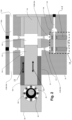
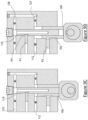
- Both the pistons 105, 115 are shown in Figure 1 in a Top Dead Center (TDC) position in their respective bores 110, 120.
- TDC Top Dead Center
- the main piston 105 can also be referred to as a secondary piston 105 and the second piston 115 can also be referred to as a secondary piston 115.
- the main piston 105 can be referred to as a first piston 105 and the secondary piston 115 can be referred to as a second piston 115.
- housing 25 can contain multiple sets the first piston 105 and the second piston 115 as multiple sets of pistons 105,115 (e.g. the housing 25 can contain two or more sets of pistons 105,115 - see Figures 16 , 17 , 18 as examples of multiple sets of pistons 105,115 for the hydraulic device 20).
- the secondary piston 115 can be concentrically positioned within the main piston 105 on the reciprocation axis 11, however other non-concentric configurations can be provided, as desired.
- the first output portion and the second output portion are fluidly coupled at the common outlet 125.
- the first input portion and the second input portion are fluidly coupled at the common inlet 135 (e.g. when the reciprocation 12 is occurring the hydraulic fluid is drawn through the input 112 and when the reciprocation 13 is occurring the hydraulic fluid is drawn through the input 113). It is recognized that the single port inlet 135 (e.g.
- a single port fitting for the housing 25 can be coupled to a common gallery 130, such that multiple sets of the pistons 105, 115 (of a multi piston pair hydraulic device 20 - see Figure 16 ) can be provided hydraulic fluid at the same time. It is also recognized that each set of pistons 105, 115 (e.g. a piston pair) would have their own flow control valves SV1, SV2, such that variable displacement mode vs full displacement mode can be controlled via each respective set of control valves SV1, SV2, or another version of the locking mechanism 14, as desired. Further, in the case of the hydraulic device 25 being a motor, inputs 112a, 113a adjacent to the flow control valves SV!, SV2 can be utilized as common galleries.
- a locking mechanism 14 for inhibiting the first reciprocal motion 12 of the main piston 105 and/or the second reciprocal motion 13 of the secondary piston 115.
- the locking mechanism 14 is the pair of flow valves (SV1, SV2, e.g. solenoid) for blocking the inflow of hydraulic fluid to either or both of the first input 112 and the second input 113, however in Figure 2 the locking mechanism 14 is unactivated.
- Both the pistons 105, 115 are shown in Figure 2 in a Bottom Dead Center (BDC) position in their respective bores 110, 120, as the actuator 85 continues to provide for both reciprocations 12, 13 together / at the same time.
- BDC Bottom Dead Center
- each piston pair 105, 115 can be controlled (for example on demand, by the operator, etc.) to switch between variable displacement mode and full displacement mode using their respective flow control valve(s) SV1, SV2 (e.g. an example locking mechanism 14) during operation of the hydraulic device 20.
- one embodiment of the locking mechanism 14 is a hydraulic locking mechanism, such that the hydraulic locking mechanism inhibits at least one of: the first input 112 from receiving the hydraulic fluid on the first intake stroke; and the first output 127 from ejecting (not shown) the hydraulic fluid on the first exhaust stroke; and/or the second input 113 from receiving the hydraulic fluid on the second intake stroke; and the second output 126 from ejecting (not shown) the hydraulic fluid on the second exhaust stroke.
- the locking mechanism 14 is a mechanical locking mechanism, such that the mechanical locking mechanism 14 inhibits the first reciprocal motion 12.
- the mechanical locking mechanism 14 includes a mechanical element positioned adjacent to a sidewall of the main piston 105, such that contact of the mechanical element with the sidewall is used to inhibit the first reciprocal motion 12.
- Figures 9A,B , C,D , E,F show a mechanical lock 14 consisting of a pin P2 positioned adjacent to a ramp W2 located in a sidewall of the piston 105, as well as a pin P1 positioned adjacent to a ramp W1 located in a sidewall of the piston 115, in various operational modes.
- the ramp W1, W2 can be formed about the periphery of the sidewall of the piston 105,115.
- the piston 115 is locked (pin P1 is engaged with ramp W1) at TDC while piston 105 is starting the exhaust stroke.
- the locking mechanism 14 can be a combination of the hydraulic locking mechanism 14 (e.g. flow control valves SV1, SV2) and the mechanical locking mechanism 14 (e.g. mechanical elements or solenoid elements). It is recognized that when using the hydraulic locking mechanism 14, the locking operation can be provided by hydraulic vacuum which is systematically created when injection into and/or ejection from a selected cylinder-piston is truncated.
- hydraulic locking mechanism 14 e.g. flow control valves SV1, SV2
- the mechanical locking mechanism 14 e.g. mechanical elements or solenoid elements
- the locking mechanism 14 for each of the piston 105, 115 pairs can be used to provide a variable displacement of the hydraulic device, such that one or both of the pistons 105,115 is disconnected from the actuator 85 for one or more selected pairs of the multi pair hydraulic device 20.
- we can activate the respective locking mechanism 14 e.g. using hydraulic lock we truncate the injection flow into the related bore 110, 120 by simply closing off the related solenoid flow control valve SV1, SV2).
- the actuator 85 drives all pistons 105, 115to TDC at which point, the piston without a new injection (e.g.
- operation of the hydraulic device 20 between the TDC and BDC positions of Figures 1 and 4 provide for a variable displacement mode of the hydraulic device 20 (i.e. only the second output portion of the hydraulic fluid is ejected from the common output 125 while the first output portion of the hydraulic fluid is withheld from the common output 125).
- operation of the hydraulic device 20 between the TDC and BDC positions of Figures 1 and 3 provide for a variable displacement mode of the hydraulic device 20 (i.e. only the first output portion of the hydraulic fluid is ejected from the common output 125 while the second output portion of the hydraulic fluid is withheld from the common output 125).
- the hydraulic device 20 can have one or more inner piston(s) 115, 250 inside the outer piston 105, such that only the outer (e.g. full time) piston 105 is in contact with the actuator 85 while the inside (e.g. part time) piston(s) 115, 250 are actuated by an actuating surface 106 (e.g. abutment surface) located on the outer piston 105.
- an actuating surface 106 e.g. abutment surface
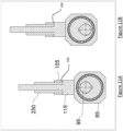
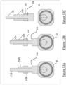
- Figure 12A shows one example operation of the hydraulic device 20 of Figures 11A,B , whereby piston 105 is locked and thus decoupled from the actuating surface 106 (once pushed to TDC by the actuating surface 106), while the piston 115 continues to be actuated by the actuator 85 and the piston 250 continues to be actuated by the surface 106.
- Figure 12B shows one example operation of the hydraulic device 20 of Figures 11A,B , whereby pistons 105,250 are locked and thus decoupled from the actuating surface 106 (once pushed to TDC by the actuating surface 106), while the piston 115 continues to be actuated by the actuator 85.
- Figure 12C shows one example operation of the hydraulic device 20 of Figures 11A,B , whereby all pistons 105, 115, 250 are locked and thus decoupled, i.e. pistons 105, 250 from the actuating surface 106 (once pushed to TDC by the actuating surface 106) and piston 115 is decoupled from the actuator 85 (once pushed to TDC by the actuator 85).
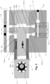
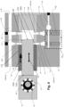
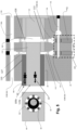
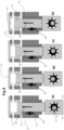
- FIG. 6A,6B,6C,6D shown is the main piston 105 is locked at TDC and thus is decoupled from the actuator 85 (i.e. the main piston 105 remains out of contact with the surface 86 and the reciprocal motion 12 is halted),while the actuator 85 is driving the secondary piston 115 between the TDC position (see Figure 6D ) and the BDC position (see Figure 6A ).
- the reciprocal motion 13 in Figures 6A, 6B, 6C, 6D is shown progressing from BDC to TDC under influence of the actuator 85 being coupled to the secondary piston 115.
- Shown in Figure 6A to Figure 6D is an exhaust stroke for the hydraulic fluid, using the secondary piston 115. It is recognized that an intake stroke for the secondary piston 115 would be the reverse, from Figure 6D to Figure 6A (i.e. from TDC to BDC).
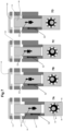
- FIG. 7A, 7B, 7C, 7D shown is the secondary piston 115 is locked at TDC and thus is decoupled from the actuator 85 (i.e. the secondary piston 115 remains out of contact with the surface 86 and the reciprocal motion 13 is halted), while the actuator 85 is driving the main piston 105 between the TDC position (see Figure 7D ) and the BDC position (see Figure 7A ).
- the reciprocal motion 12 in Figures 7A, 7B, 7C, 7D is shown progressing from BDC to TDC under influence of the actuator 85 being coupled to the main piston 105.
- Shown in Figure 7A to Figure 7D is an exhaust stroke for the hydraulic fluid, using the main piston 105. It is recognized that an intake stroke for the main piston 105 would be the reverse, from Figure 7D to Figure 7A (i.e. from TDC to BDC).
- both pistons 105,115 are locked at TDC and thus are decoupled from the actuator 85 (i.e. both pistons 105,115 remain out of contact with the surface 86 and the reciprocal motions 12, 13 are halted), while the actuator 85 rotates between the TDC position (see Figure 8D ) and the BDC position (see Figure 8A ).
- the actuator 85 can always drive all pistons 105,115 to TDC, at which point, the piston 105, 115 without a new injection (having a closed flow control valve SV1, SV2) will be held at TDC by way of mechanical or vacuum lock. Once held, the piston(s) 105, 115 will become decoupled from the actuator 85 and the held piston(s) 105,115 at TDC will no longer contribute to the outlet flow volume in their respective outputs 126, 127.
- re-engaging the disconnected piston(s) 105,115 to become once again coupled to the actuator 85 can be facilitated by re-opening the related flow control valve(S) SV1, SV2 to allow flow into the related bore 110, 120 via the input 112a, 113a.
- the piston(s) 105, 115 will be pushed closer to the actuator 85 in order to reengage with the actuator 85, no matter what position the actuator 85 may be during the reengagement.
- the actuator 85 can be travelling in the same or opposite direction as the piston(s) 105, 115 during reengagement of the piston(s) 105,115.
- both the piston(s) 105, 115 and the actuator 85 could both be moving towards BDC (i.e. both travelling in the same direction during the intake stroke). In this manner the piston(s) 105, 115 will recouple with the actuator 85 on their downward travel towards BDC, so that the recoupled piston(s) 105,115 will travel with the actuator 85 once again towards TDC (e.g. during the exhaust stroke). Once recoupled, the piston(s) 105,115 continue their reciprocal motion 12,13 until such time as their flow control valve(s) SV1, SV2 become closed once again.
- both the piston(s) 105, 115 and the actuator 85 could both be moving in opposite directions (i.e. the actuator 85 towards TDC and the piston(s) 105, 115 towards BDC during a designated exhaust stroke).
- the piston(s) 105, 115 will recouple with the actuator 85 on their downward travel towards BDC, as the actuator 85 comes up to meet the downward travelling piston(s) 105,115, so that the recoupled piston(s) 105,115 will travel with the actuator 85 once again towards TDC (e.g. during the exhaust stroke, in this case a partial exhaust stroke measured from the point of reengagement somewhere between BDC and TDC).
- the piston(s) 105,115 Once recoupled, the piston(s) 105,115 would continue their reciprocal motion 12,13 until such time as their flow control valve(s) SV1, SV2 become closed once again. Therefore, it is recognized in this embodiment of reengagement, the exhaust stroke of the reengaged piston(s) 105, 115 would only be a partial exhaust stroke (i.e. only a partial bore volume of oil would be ejected from the outlet 126, 127 - in essence the amount of oil in the bore 110, 120 at the point where the upwards travelling actuator 85 reengages with the piston(s) 105, 115 somewhere between BDC and TDC).
- the re-engagement of the piston(s) 105, 115 to the actuator 85 is advantageously not disruptive (i.e. undesirable impact / collision between the actuator 85 and the piston(s) 105, 115) due to one or more of the following; a) layers of oil between the actuator surface 86 and the piston surface(S) 105b, 115b can act as buffer or shock absorber; b) as the piston(s) 105, 115 changes direction back towards TDC, following engagement with the upwards travelling actuator 85, the piston(s) 105, 115 will not encounter a "dead-head" condition as a small volume of oil can be released past the inlet check valve 112 while the inlet check valve is closing (e.g.
- the position of the actuator 85 could be monitored (e.g. by a position sensor, by a controller based on position of the drive shaft 95, etc.) so that the flow control valve(s) SV1, SV2 would only be reopened when the actuator 85 is at the TDC position.
- each of the inlets 112, 113 have a respective entrance 112a, 113a, in order to isolate (e.g. starve) each inlet 112,113 of the multi-pair hydraulic device 20 when the respective flow control valve(s) SV1, SV2 is / are closed.
- each of the piston pairs 105, 115 would have a respective lock mechanism 14 (e.g. a respective set of flow control valves SV1,SV2). In this manner, each piston 105, 115 of each piston pair 105,115 can be controlled in either a locked or unlocked manner. Also, it is preferred to have valves (e.g. check valves CV) at each entrance and exit of the cylinder bores 110,120, in order to facilitate proper flow (e.g. prevent cross talk between adjacent pairs of the pistons 105, 115) of the hydraulic fluid between the inlet 135 and the outlet 125 during operation of the hydraulic device 20. Thus, shown is a head end-cap 140, as well as the inlet and outlet check valves CV.
- valves e.g. check valves CV
- a first check valve CV can be positioned in the first input 112, a second check valve CV positioned in the first output 127, a third check valve CV positioned in the second input 113 and a fourth check valve CV positioned in the second output 126.
- unlocking of the flow control valve(s) SV1, SV2 could be timed off the main shaft 95 (or remain untimed as discussed above as one embodiment) so that the unlocking of a locked piston would coincide with the proper positioning of the actuator block 85 (i.e. the surface 86 would be in position adjacent to the end 105b, 115b at TDC) when the respective flow control valve SV1,SV2 is unlocked.
- the untimed mode there is no need to time the position of the actuator 85 on reengaging with the piston(s) 105, 115 after lockdown, which would result in the partial exhaust stroke on reengagement of the piston(s) with the actuator 85.
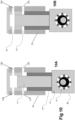
- FIG. 10A,B shown is a further embodiment of the hydraulic device 20, such that the housing 25 has a pair of inlets 112, 113 and a pair of outlets 126,127, such that each piston 105, 115 has a respective individual inlet 112, 113 and a respective individual outlet 127, 126.
- the output flows e.g. first portion and second portion
- both pistons 105, 115 are at BDC and are starting an exhaust stroke.
- both pistons 105, 115 are at TDC and are thus at the end of their exhaust strokes, resulting in a first portion of the hydraulic fluid output exiting the first outlet 127 and a second portion of the hydraulic fluid output exiting the separate (from the first outlet 127) second outlet 126.
- the actuator 85 can include an eccentric cam 100 driven off the shaft 95, the eccentric cam 100 having a first cam surface 100a for contacting the second main end 105a and a second cam surface 100b for contacting the second secondary end 115b during the first reciprocal motion 12 and the second reciprocal motion 13, such that the first cam surface 100a is offset from the second cam surface 100b.
- an offset cam having a first cam 100a offset (e.g. by 180 degrees) from a second cam 100b, such that both the first cam 100a and the second cam 100b are mounted on the same shaft 95.
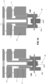
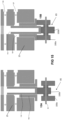
- the pistons 105,115 alternate separately between their TDC and BDC positions. For example, when offset by 180 degrees, the main piston 105 would be at BDC when the secondary piston 115 is at TDC, see Figure 13A .
- the cams 110a, 100b are further rotated by the shaft 95, then the positions of the pistons 105, 115 would eventually switch, i.e. the main piston 105 would be at TDC when the secondary piston 115 is at BDC, see Figure 13B .
- the locking mechanism 14 (see Figure 2 ) is unactivated (both flow valves SV1 and SV2 are open) and thus both pistons 105, 115 are reciprocating 12,13 as the drive shaft 95 rotates.
- the actuator 85 having the offset cam having the first cam 100a offset (e.g. by 180 degrees) from the second cam 100b, such that both the first cam 100a and the second cam 100b are mounted on the same shaft 95.
- the pistons 105,115 can be alternated between their TDC and BDC positions.
- the locking mechanism 14 (see Figure 3 ) is activated (flow valve SV1 is open and flow valve SV2 is closed) and thus the main piston 105 is reciprocating 12 as the drive shaft 95 rotates while the secondary piston 115 remains locked (i.e. held in position at TDC).
- the main piston 105 when offset by 180 degrees, the main piston 105 is at BDC when the secondary piston 115 is held at TDC, see Figure 14A .
- the cams 110a, 100b are further rotated by the shaft 95, then the position of the main piston 105 would change, i.e. the main piston 105 would be at TDC while the secondary piston 115 remains stationary at TDC (and is decoupled from the cam 110b), see Figure 14B .
- the actuator 85 having the offset cam having the first cam 100a offset (e.g. by 180 degrees) from the second cam 100b, such that both the first cam 100a and the second cam 100b are mounted on the same shaft 95.
- the pistons 105,115 can be alternated between their TDC and BDC positions.
- the locking mechanism 14 (see Figure 4 ) is activated (flow valve SV1 is closed and flow valve SV2 is open) and thus the secondary piston 115 is reciprocating 13 as the drive shaft 95 rotates while the main piston 105 remains locked (i.e. held in position at TDC).
- the secondary piston 115 when offset by 180 degrees, the secondary piston 115 is at TDC when the main piston 105 is held at TDC, see Figure 15A .
- the cams 110a, 100b are further rotated by the shaft 95, then the position of the secondary piston 115 would change, i.e. the secondary piston 115 would be at BDC while the main piston 115 remains stationary at TDC (and is decoupled from the cam 110a), see Figure 15B .
- the hydraulic device 20 can be a pump as shown or can also be a motor.
- the reciprocation(s) 12,13 of the piston(s) 105, 115 would drive the rotation of the shaft 95 by the respective end(s) 105b, 115b driving the contact surface(s) 86.
- the input of the hydraulic fluid into the input(s) 112, 113 would be used to drive the reciprocation(s) 12, 13 and thus the rotation of the shaft 95.
- variable displacement e.g. using the locking mechanism 14 as described above
- variable displacement could be used by the hydraulic device 20 to moderate the torque and / or speed of the motor operation, as desired.
- the pistons 110, 115 have a fixed stroke length when reciprocating in their respective bores (i.e. cylinders 110,120). As such, a distance between a Top Dead Center TDC and Bottom Dead Center BDC remains constant when the locking mechanism 14 (e.g. flow control valves SV1,SV2)is operated between a closed / locked state and an open / unlocked state.
- the position TDC can be defined as when the piston 110, 115 reaches the end of the exhaust stroke for ejecting fluid out of the cylinder 110, 120, and thus the beginning of the intake stroke for injecting fluid into the cylinder 110, 120.
- the position BDC can be defined as when the piston 110, 115 reaches the end of the intake stroke for injecting fluid into the cylinder 110, 120, and thus the beginning of the exhaust stroke for ejecting fluid out of the cylinder 110, 120.
- the configuration of the piston 105 - cylinder 110 and piston 115 - cylinder 120 arrangements can be referred to as an axial configuration.
- hydraulic device 20 having a plurality of piston 105 - cylinder 110 and piston 115 - cylinder 120 arrangements.
- the hydraulic device 20 can have any number of piston- cylinder arrangements, e.g. 5, 7, 9, etc.
- each internal piston 115 (or a multi piston device 20) can be of different surface area than the next one, which could provide for allows for the outlet flow reduction (i.e. variable displacement) to be nonlinear.
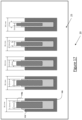
- each pair of pistons includes the outer piston 105 and the inner piston 115. It is recognized that one or more of the pairs of pistons 105, 115 can have different diameters (with corresponding bores), the differing numerical sizes of the pistons 105, 115 shown by example only. In this manner, depending upon which piston(s) 105, 115 is/are decoupled from the actuator 85 (not shown in Figure 16 for simplicity, rather see Figure 1 for an example of the actuator 85), the hydraulic device 20 could have a selected difference in the variable displacement provided.
- decoupling the 17mm inner piston 115 would subtract less from the total output of the hydraulic device 20 (in the case of a pump) than in the case of decoupling the 21mm piston 115. In this manner, not only the decision to decouple a piston 115 (or corresponding piston 105 for that matter) can be made by the operator of the hydraulic device 20, but also the size of the piston 105, 115.
- piston 105 is the outer most piston
- piston 115 is the intermediate piston
- piston 115B is the inner most piston.
- Shown in Figure 17 is a plurality of different sizes of the pistons 105, 115, 115B, however it is also recognized that similar sized pistons 105, 115, 115B can be provided, as desired (e.g. similar to the embodiment of Figure 1 for pairs 105, 115 of pistons). As such, each piston 115 and piston 115B can be of a different bore diameter to each other.
- piston 115B of diameter 21mm will, per revolution, displace a lesser volume than piston 115B of 23mm and so forth.
- piston 115 of 23mm will, per revolution, displace a lesser volume than piston 115 of 25mm and so forth.
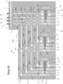
- each set of pistons (e.g. nested pistons) has an outer piston 105A, a first piston 105B positioned inside the outer piston 105A, a second piston 105C positioned inside the first piston 105B and a third piston 105D positioned within the second piston 105C.
- Each of the pistons is positioned within a corresponding bore 107A, 107B, 107C, 107D, such that at least a portion of bore 107B is within the outer piston 105A, at least a portion of bore 107C is within the first piston 105B, and at least a portion of bore 107D is within the second piston 105C.
- the bore 107A is within the housing 25. It is recognized that the bores 107A,B,C,D are not in fluid communication with one another, rather any fluid communication between the bores 107A,B,C,D of the same piston set 105A,B,C,D is inhibited by the bodies of the intervening pistons 105A,B,C,D.
- Each of the pistons 105A, 105B, 105C, 105D are configured to reciprocate axially along the reciprocation axis 11, see Figure 1 , in conjunction with the actuator ACT1, ACT2, ACT3. It is recognized that each set of piston in pistons 105A,B,C,D has a corresponding shared actuator ACT1,2,3 (e.g. each actuator ACT1,ACT2,ACT3 drives / is driven with respect to the set of pistons 105A,B,C,D). Not shown is Figure 18 for the purpose of ease of portrayal only, is the shaft 95 and cam 100 (see Figure 1 ) as part of the actuators ACT1, ACT2, ACT3. For example, each actuator ACT1,2,3 is driven off the same shaft 95 by a respective cam 100 (not shown). SLE refers to the set of piston bores 107A, B, C, D.
- the bores 107A,B,C,D are not in fluid communication with one another, rather any fluid communication between the bores 107A,B,C,D of the same piston set 105A,B,C,D is inhibited by the bodies of the intervening pistons 105A,B,C,D.
- first piston 105B is positioned during its reciprocation such that the body of the first piston 105B inhibits fluid communication between the bore 107A and the bore 107B (recognizing that piston seals - not shown - between the pistons 105A,B,C,D and the walls of the respective bores 107A,B,C,D can also thus facilitate the inhibition of fluid communication between the bores 107A,B,C,D).
- the body of second piston 105C is positioned during its reciprocation such that the body of the second piston 105C inhibits fluid communication between the bore 107B and the bore 107C.
- the body of third piston 105D is positioned during its reciprocation such that the body of the third piston 105D inhibits fluid communication between the bore 107C and the bore 107D.
- control valve SOL1 controls the reciprocation state (locked or unlocked) of all outer pistons 105A, such that operation of the flow control valve SOL1 either locks all outer pistons 105A from all the sets of pistons 105A,B,C,D or unlocks all outer pistons 105A from all the sets of pistons 105A,B,C,D.
- control valve SOL2 controls the reciprocation state (locked or unlocked) of all first pistons 105B, such that operation of the flow control valve SOL2 either locks all first pistons 105B from all the sets of pistons 105A,B,C,D or unlocks all first pistons 105B from all the sets of pistons 105A,B,C,D.
- control valve SOL3 controls the reciprocation state (locked or unlocked) of all second pistons 105C, such that operation of the flow control valve SOL3 either locks all second pistons 105C from all the sets of pistons 105A,B,C,D or unlocks all second pistons 105C from all the sets of pistons 105A,B,C,D.
- control valve SOL34 controls the reciprocation state (locked or unlocked) of all third pistons 105D, such that operation of the flow control valve SOL4 either locks all third pistons 105D from all the sets of pistons 105A,B,C,D or unlocks all third pistons 105D from all the sets of pistons 105A,B,C,D.
- each flow control valve SOL1,SOL2,SOL3,SOL4 controls two or more pistons 105A,105B,105C,105D, such that the two or more pistons 105A, 105B, 105C, 105D controlled are from different sets of pistons 105A,B,C,D.
- This configuration is different form the hydraulic device 20 shown in Figure 1 , whereby each flow control valves SV1,SV2 only controls one respective piston 105, 115.
- the flow control valves SOL1,SOL2,SOL3,SOL4 are configured in a one to many setup (e.g. one flow control valve for many pistons) while the flow control valves SV1,SV2 are configured in a one to one setup (e.g. one flow control valve for one piston).
- the passage IN is a common gallery for the housing 25 whereby hydraulic fluid is either facilitated to enter the bore 107A,B,C,D by the respective flow control valves SOL1,SOL2,SOL3,SOL4 (e.g. in an open / unlocked state) or is either restricted from entering the bore 107A,B,C,D by the respective flow control valves SOL1,SOL2,SOL3,SOL4 (e.g. in a closed / locked state).
- the passage IN can be referred to as an inlet or feed port for the hydraulic device 20.
- P1 represents the outlet port for each of the flow control valves SOL1,SOL2,SOL3,SOL4 while P2 represents the inlet port for each of the flow control valves SOL1,SOL2,SOL3,SOL4 (e.g. when a flow control valve SOL1,SOL2,SOL3,SOL4 is closed / locked, hydraulic oil is inhibited from flowing through its inlet port P2 and out of its outlet port P1).
- POR1, POR2, POR3, POR4 are the respective inlet passages connecting the respective outlet port P1 of each of the flow control valves SOL1,SOL2,SOL3,SOL4 with a respective common gallery CG1,CG2,CG3,CG4.
- passage POR1 is used to direct hydraulic oil from the outlet port P1 of flow control valve SOL1 to each of the bores 107A of the outer pistons 105A.
- passage POR2 is used to direct hydraulic oil from the outlet port P1 of flow control valve SOL2 to each of the bores 107B of the outer pistons 105B.
- passage POR3 is used to direct hydraulic oil from the outlet port P1 of flow control valve SOL3 to each of the bores 107C of the outer pistons 105C.
- passage POR4 is used to direct hydraulic oil from the outlet port P1 of flow control valve SOL4 to each of the bores 107D of the outer pistons 105D.
- respective passages POR5,6,7,8 are used to direct hydraulic fluid from the respective common galleries CG1,2,3,4.
- hydraulic fluid entering from passage POR1 into common gallery CG1 then exits into passage POR5.
- hydraulic fluid entering from passage POR2 into common gallery CG2 then exits into passage POR6.
- hydraulic fluid entering from passage POR3 into common gallery CG3 then exits into passage POR7.
- hydraulic fluid entering from passage POR4 into common gallery CG4 then exits into passage POR8.
- the respective passages POR5,6,7,8 fluidly connect each respective common gallery CG1,2,3,4 with a respective passage connecting point CPO1,2,3,4.
- the passage connecting point CPO1,2,3,4 provides for fluid communication between adjacent passages POR9,10,11,12 (e.g. passage connecting points CPO1 fluidly connect passage POR5 with passages POR9, passage connecting points CPO2 fluidly connect passage POR6 with passages POR10, passage connecting points CPO3 fluidly connect passage POR7 with passages POR11, passage connecting points CPO4 fluidly connect passage POR8 with passages POR12).
- the common gallery CG1 can be used to connect the respective passage POR1 with a respective passage POR9, thus functioning as a fluid connecting point.
- the common gallery CG2 can be used to connect the respective passage POR2 with a respective passage POR10, thus functioning as a fluid connecting point.
- the common gallery CG3 can be used to connect the respective passage POR3 with a respective passage POR11, thus functioning as a fluid connecting point.
- the common gallery CG4 can be used to connect the respective passage POR4 with a respective passage POR12, thus functioning as a fluid connecting point.
- each of the symbols referenced by the reference indicator NCPO refers to a non-connecting point, such that the crossed passages are not in fluid communication with one another within the housing 25.
- the symbol NCPO shown indicates that the passage POR7 is not in fluid communication with the passage POR12, the passage POR6 is not in fluid communication with the passages POR11, 12, etc.
- the respective common galleries CG1,2,3,4 direct hydraulic fluid to each of their respective connecting points CG1,2,3,4.
- common gallery CG1 fluidly communicates with all the connecting points CPO1
- common gallery CG2 fluidly communicates with all the connecting points CPO2
- common gallery CG3 fluidly communicates with all the connecting points CPO3
- common gallery CG4 fluidly communicates with all the connecting points CPO4.
- each of the respective common galleries CG1,2,3,4 fluidly communicates with the respective passages POR9,10,11,12.
- each OUT is an outlet passage from the various sets of pistons 105A,B,C,D.
- each of the flow control valves SOL1,SOL2,SOL3,SOL4 can be normally opened (e.g. deenergized) so supply hydraulic fluid can fill all bores 107A,B,C,D (in the case of a hydraulic pump). If one (or more) of the flow control valves SOL1,SOL2,SOL3,SOL4 is closed (e.g. energized), hydraulic fluid flow to all related bores is truncated. For example, if the flow control valve SOL1 is closed then hydraulic fluid cannot flow to all the bores 107A for all the outer pistons 105A.
- the flow control valve SOL2 is closed then hydraulic fluid cannot flow to all the bores 107B for all the first pistons 105B.
- the flow control valve SOL3 is closed then hydraulic fluid cannot flow to all the bores 107C for all the second pistons 105C.
- the flow control valve SOL4 is closed then hydraulic fluid cannot flow to all the bores 107D for all the third pistons 105D. It is recognized that one or more of the flow control valves SOL1,SOL2,SOL3,SOL4 can be closed at the same time. It is recognized that one or more of the flow control valves SOL1,SOL2,SOL3,SOL4 can be open at the same time.
- each of the inlets e.g. IN, P2
- each of the outlets e.g. OUT, P1
- the rotation of the driveshaft 95 can be reversible, i.e. done is a clockwise or in counterclockwise rotation as desired.
- each of the outer pistons 105 could be controlled by a respective flow control valve SV1 (e.g. a one control valve SV1 to one piston 105 configuration for each set of pistons).
- all of the inner pistons 115 could be controlled by a shared flow control valve SOL2 (e.g. a one control valve SOL2 to many pistons 115 configuration for each set of pistons).
- the flow control valves SOL1,SOL2,SOL3,SOL4 can be referred to as one example of a locking mechanism (e.g. a hydraulic locking mechanism). As such it is recognized that any / all of the flow control valves SOL1,SOL2,SOL3,SOL4 could be substituted for a mechanical locking mechanism type, such as shown by example in Figures 9A-F ).
- a locking mechanism e.g. a hydraulic locking mechanism
- any / all of the flow control valves SOL1,SOL2,SOL3,SOL4 could be substituted for a mechanical locking mechanism type, such as shown by example in Figures 9A-F ).
- the present invention is defined in the claims, it should be understood that the present invention can also (alternativley) be defined in accordance with the following embodiments:
Landscapes
- Engineering & Computer Science (AREA)
- Mechanical Engineering (AREA)
- General Engineering & Computer Science (AREA)
- Actuator (AREA)
Priority Applications (1)
| Application Number | Priority Date | Filing Date | Title |
|---|---|---|---|
| EP26155627.8A EP4715212A3 (de) | 2023-06-09 | 2024-05-10 | Kolben in einer hydraulischen vorrichtung mit variabler verdrängung |
Applications Claiming Priority (3)
| Application Number | Priority Date | Filing Date | Title |
|---|---|---|---|
| US202363472197P | 2023-06-09 | 2023-06-09 | |
| US202363547482P | 2023-11-06 | 2023-11-06 | |
| US18/536,668 US11994121B1 (en) | 2023-06-09 | 2023-12-12 | Piston in piston variable displacement hydraulic device |
Related Child Applications (1)
| Application Number | Title | Priority Date | Filing Date |
|---|---|---|---|
| EP26155627.8A Division EP4715212A3 (de) | 2023-06-09 | 2024-05-10 | Kolben in einer hydraulischen vorrichtung mit variabler verdrängung |
Publications (2)
| Publication Number | Publication Date |
|---|---|
| EP4474643A1 true EP4474643A1 (de) | 2024-12-11 |
| EP4474643B1 EP4474643B1 (de) | 2026-02-04 |
Family
ID=91072721
Family Applications (1)
| Application Number | Title | Priority Date | Filing Date |
|---|---|---|---|
| EP24175287.2A Active EP4474643B1 (de) | 2023-06-09 | 2024-05-10 | Kolben in einer hydraulischen vorrichtung mit variabler verdrängung |
Country Status (1)
| Country | Link |
|---|---|
| EP (1) | EP4474643B1 (de) |
Citations (3)
| Publication number | Priority date | Publication date | Assignee | Title |
|---|---|---|---|---|
| FR1148819A (fr) * | 1956-02-27 | 1957-12-16 | Pompe perfectionnée | |
| US9175676B2 (en) * | 2009-12-08 | 2015-11-03 | Les Chaussures Stc Inc. | Fluid compression system |
| CN110657080A (zh) * | 2019-09-10 | 2020-01-07 | 河南科技大学 | 用于短行程液压缸液压装置的双速手动加压泵 |
-
2024
- 2024-05-10 EP EP24175287.2A patent/EP4474643B1/de active Active
Patent Citations (3)
| Publication number | Priority date | Publication date | Assignee | Title |
|---|---|---|---|---|
| FR1148819A (fr) * | 1956-02-27 | 1957-12-16 | Pompe perfectionnée | |
| US9175676B2 (en) * | 2009-12-08 | 2015-11-03 | Les Chaussures Stc Inc. | Fluid compression system |
| CN110657080A (zh) * | 2019-09-10 | 2020-01-07 | 河南科技大学 | 用于短行程液压缸液压装置的双速手动加压泵 |
Also Published As
| Publication number | Publication date |
|---|---|
| EP4474643B1 (de) | 2026-02-04 |
Similar Documents
| Publication | Publication Date | Title |
|---|---|---|
| CA3238003C (en) | Piston in piston variable displacement hydraulic device | |
| US20110041681A1 (en) | Positive-displacement machine | |
| KR102664199B1 (ko) | 유압 펌프 | |
| EP0898653B1 (de) | Hydraulisches regelsystem für den druck einer pumpe | |
| JPH05507993A (ja) | ラジアルピストン流体装置及び/又は調整自在ロータ | |
| CA2793397A1 (en) | System, apparatus, and method for rapid pump displacement configuration | |
| US20130343914A1 (en) | Variable radial fluid device with differential piston control | |
| EP2679820A1 (de) | Variable radiale Flüssigkeitsvorrichtung mit entgegenwirkenden Nocken | |
| CN108700058B (zh) | 用于可下潜应用的线性液压泵 | |
| EP4474643B1 (de) | Kolben in einer hydraulischen vorrichtung mit variabler verdrängung | |
| WO2008025395A1 (de) | Steuereinrichtung für eine hydraulische kolben maschine mit veränderbarem volumenstrom | |
| DE102007054547A1 (de) | Motorsteuerstrategie für hydraulischen Nockenwellenversteller mit mechanischer Mittenverriegelung | |
| CN100339567C (zh) | 阀门开关定时控制装置 | |
| EP0848140A1 (de) | Variable Ventilsteuerungseinrichtung | |
| EP3535493B1 (de) | Verfahren zum steuern des drehmomentgleichgewichts eines hydraulikmotors | |
| US20220325729A1 (en) | Cylinder on demand hydraulic device | |
| EP2189658B1 (de) | Flüssigkeitspumpenanordnung | |
| US12320412B2 (en) | Axial piston variable displacement hydraulic devices, such as hydraulic motors, and methods of operating same | |
| US11333145B2 (en) | Cylinder on demand hydraulic device | |
| AU745650B2 (en) | Spool valve for fluid control | |
| US11293461B2 (en) | Cylinder on demand hydraulic device | |
| US11506229B2 (en) | Modular hydraulic device | |
| EP4502375A1 (de) | Hydraulische rotationskolbenpumpe mit taumelscheibe | |
| DE102006000832A1 (de) | Radialkolbenpumpe mit Fördermengenregelung | |
| DE69025948T2 (de) | Hydraulisches Energiegetriebe |
Legal Events
| Date | Code | Title | Description |
|---|---|---|---|
| PUAI | Public reference made under article 153(3) epc to a published international application that has entered the european phase |
Free format text: ORIGINAL CODE: 0009012 |
|
| STAA | Information on the status of an ep patent application or granted ep patent |
Free format text: STATUS: THE APPLICATION HAS BEEN PUBLISHED |
|
| AK | Designated contracting states |
Kind code of ref document: A1 Designated state(s): AL AT BE BG CH CY CZ DE DK EE ES FI FR GB GR HR HU IE IS IT LI LT LU LV MC ME MK MT NL NO PL PT RO RS SE SI SK SM TR |
|
| STAA | Information on the status of an ep patent application or granted ep patent |
Free format text: STATUS: REQUEST FOR EXAMINATION WAS MADE |
|
| 17P | Request for examination filed |
Effective date: 20250611 |
|
| GRAP | Despatch of communication of intention to grant a patent |
Free format text: ORIGINAL CODE: EPIDOSNIGR1 |
|
| STAA | Information on the status of an ep patent application or granted ep patent |
Free format text: STATUS: GRANT OF PATENT IS INTENDED |
|
| INTG | Intention to grant announced |
Effective date: 20250908 |
|
| GRAS | Grant fee paid |
Free format text: ORIGINAL CODE: EPIDOSNIGR3 |
|
| GRAA | (expected) grant |
Free format text: ORIGINAL CODE: 0009210 |
|
| STAA | Information on the status of an ep patent application or granted ep patent |
Free format text: STATUS: THE PATENT HAS BEEN GRANTED |
|
| AK | Designated contracting states |
Kind code of ref document: B1 Designated state(s): AL AT BE BG CH CY CZ DE DK EE ES FI FR GB GR HR HU IE IS IT LI LT LU LV MC ME MK MT NL NO PL PT RO RS SE SI SK SM TR |
|
| REG | Reference to a national code |
Ref country code: CH Ref legal event code: F10 Free format text: ST27 STATUS EVENT CODE: U-0-0-F10-F00 (AS PROVIDED BY THE NATIONAL OFFICE) Effective date: 20260204 Ref country code: GB Ref legal event code: FG4D |
|
| REG | Reference to a national code |
Ref country code: DE Ref legal event code: R096 Ref document number: 602024002365 Country of ref document: DE |
|
| REG | Reference to a national code |
Ref country code: IE Ref legal event code: FG4D |
|
| REG | Reference to a national code |
Ref country code: NL Ref legal event code: MP Effective date: 20260204 |
|
| PG25 | Lapsed in a contracting state [announced via postgrant information from national office to epo] |
Ref country code: RS Free format text: LAPSE BECAUSE OF FAILURE TO SUBMIT A TRANSLATION OF THE DESCRIPTION OR TO PAY THE FEE WITHIN THE PRESCRIBED TIME-LIMIT Effective date: 20260504 |
|
| PG25 | Lapsed in a contracting state [announced via postgrant information from national office to epo] |
Ref country code: ES Free format text: LAPSE BECAUSE OF FAILURE TO SUBMIT A TRANSLATION OF THE DESCRIPTION OR TO PAY THE FEE WITHIN THE PRESCRIBED TIME-LIMIT Effective date: 20260204 |
|
| PG25 | Lapsed in a contracting state [announced via postgrant information from national office to epo] |
Ref country code: PL Free format text: LAPSE BECAUSE OF FAILURE TO SUBMIT A TRANSLATION OF THE DESCRIPTION OR TO PAY THE FEE WITHIN THE PRESCRIBED TIME-LIMIT Effective date: 20260204 |
|
| PG25 | Lapsed in a contracting state [announced via postgrant information from national office to epo] |
Ref country code: GR Free format text: LAPSE BECAUSE OF FAILURE TO SUBMIT A TRANSLATION OF THE DESCRIPTION OR TO PAY THE FEE WITHIN THE PRESCRIBED TIME-LIMIT Effective date: 20260505 |
|
| PGFP | Annual fee paid to national office [announced via postgrant information from national office to epo] |
Ref country code: IT Payment date: 20260601 Year of fee payment: 3 |
|
| REG | Reference to a national code |
Ref country code: LT Ref legal event code: MG9D |
|
| PG25 | Lapsed in a contracting state [announced via postgrant information from national office to epo] |
Ref country code: LT Free format text: LAPSE BECAUSE OF FAILURE TO SUBMIT A TRANSLATION OF THE DESCRIPTION OR TO PAY THE FEE WITHIN THE PRESCRIBED TIME-LIMIT Effective date: 20260204 |
|
| PGFP | Annual fee paid to national office [announced via postgrant information from national office to epo] |
Ref country code: DE Payment date: 20260522 Year of fee payment: 3 |
|
| PG25 | Lapsed in a contracting state [announced via postgrant information from national office to epo] |
Ref country code: NO Free format text: LAPSE BECAUSE OF FAILURE TO SUBMIT A TRANSLATION OF THE DESCRIPTION OR TO PAY THE FEE WITHIN THE PRESCRIBED TIME-LIMIT Effective date: 20260504 |
|
| PG25 | Lapsed in a contracting state [announced via postgrant information from national office to epo] |
Ref country code: FI Free format text: LAPSE BECAUSE OF FAILURE TO SUBMIT A TRANSLATION OF THE DESCRIPTION OR TO PAY THE FEE WITHIN THE PRESCRIBED TIME-LIMIT Effective date: 20260204 Ref country code: AT Free format text: LAPSE BECAUSE OF FAILURE TO SUBMIT A TRANSLATION OF THE DESCRIPTION OR TO PAY THE FEE WITHIN THE PRESCRIBED TIME-LIMIT Effective date: 20260204 Ref country code: SE Free format text: LAPSE BECAUSE OF FAILURE TO SUBMIT A TRANSLATION OF THE DESCRIPTION OR TO PAY THE FEE WITHIN THE PRESCRIBED TIME-LIMIT Effective date: 20260204 |
|
| REG | Reference to a national code |
Ref country code: AT Ref legal event code: MK05 Ref document number: 1884165 Country of ref document: AT Kind code of ref document: T Effective date: 20260204 |
|
| PG25 | Lapsed in a contracting state [announced via postgrant information from national office to epo] |
Ref country code: HR Free format text: LAPSE BECAUSE OF FAILURE TO SUBMIT A TRANSLATION OF THE DESCRIPTION OR TO PAY THE FEE WITHIN THE PRESCRIBED TIME-LIMIT Effective date: 20260204 |
|
| PG25 | Lapsed in a contracting state [announced via postgrant information from national office to epo] |
Ref country code: PT Free format text: LAPSE BECAUSE OF FAILURE TO SUBMIT A TRANSLATION OF THE DESCRIPTION OR TO PAY THE FEE WITHIN THE PRESCRIBED TIME-LIMIT Effective date: 20260605 Ref country code: IS Free format text: LAPSE BECAUSE OF FAILURE TO SUBMIT A TRANSLATION OF THE DESCRIPTION OR TO PAY THE FEE WITHIN THE PRESCRIBED TIME-LIMIT Effective date: 20260604 |
|
| PG25 | Lapsed in a contracting state [announced via postgrant information from national office to epo] |
Ref country code: NL Free format text: LAPSE BECAUSE OF FAILURE TO SUBMIT A TRANSLATION OF THE DESCRIPTION OR TO PAY THE FEE WITHIN THE PRESCRIBED TIME-LIMIT Effective date: 20260204 |
|
| PGFP | Annual fee paid to national office [announced via postgrant information from national office to epo] |
Ref country code: FR Payment date: 20260525 Year of fee payment: 3 |
|
| PG25 | Lapsed in a contracting state [announced via postgrant information from national office to epo] |
Ref country code: LV Free format text: LAPSE BECAUSE OF FAILURE TO SUBMIT A TRANSLATION OF THE DESCRIPTION OR TO PAY THE FEE WITHIN THE PRESCRIBED TIME-LIMIT Effective date: 20260204 |
|
| PG25 | Lapsed in a contracting state [announced via postgrant information from national office to epo] |
Ref country code: BG Free format text: LAPSE BECAUSE OF FAILURE TO SUBMIT A TRANSLATION OF THE DESCRIPTION OR TO PAY THE FEE WITHIN THE PRESCRIBED TIME-LIMIT Effective date: 20260204 |