EP4474606A1 - Quick installation frame for security doors - Google Patents
Quick installation frame for security doors Download PDFInfo
- Publication number
- EP4474606A1 EP4474606A1 EP24180004.4A EP24180004A EP4474606A1 EP 4474606 A1 EP4474606 A1 EP 4474606A1 EP 24180004 A EP24180004 A EP 24180004A EP 4474606 A1 EP4474606 A1 EP 4474606A1
- Authority
- EP
- European Patent Office
- Prior art keywords
- frame
- gate
- interior
- exterior
- branch
- Prior art date
- Legal status (The legal status is an assumption and is not a legal conclusion. Google has not performed a legal analysis and makes no representation as to the accuracy of the status listed.)
- Granted
Links
Images


Classifications
-
- E—FIXED CONSTRUCTIONS
- E06—DOORS, WINDOWS, SHUTTERS, OR ROLLER BLINDS IN GENERAL; LADDERS
- E06B—FIXED OR MOVABLE CLOSURES FOR OPENINGS IN BUILDINGS, VEHICLES, FENCES OR LIKE ENCLOSURES IN GENERAL, e.g. DOORS, WINDOWS, BLINDS, GATES
- E06B1/00—Border constructions of openings in walls, floors, or ceilings; Frames to be rigidly mounted in such openings
- E06B1/04—Frames for doors, windows, or the like to be fixed in openings
- E06B1/34—Coverings, e.g. protecting against weather, for decorative purposes
- E06B1/347—Renovation door frames covering the existing old frames
-
- E—FIXED CONSTRUCTIONS
- E06—DOORS, WINDOWS, SHUTTERS, OR ROLLER BLINDS IN GENERAL; LADDERS
- E06B—FIXED OR MOVABLE CLOSURES FOR OPENINGS IN BUILDINGS, VEHICLES, FENCES OR LIKE ENCLOSURES IN GENERAL, e.g. DOORS, WINDOWS, BLINDS, GATES
- E06B1/00—Border constructions of openings in walls, floors, or ceilings; Frames to be rigidly mounted in such openings
- E06B1/56—Fastening frames to the border of openings or to similar contiguous frames
-
- E—FIXED CONSTRUCTIONS
- E06—DOORS, WINDOWS, SHUTTERS, OR ROLLER BLINDS IN GENERAL; LADDERS
- E06B—FIXED OR MOVABLE CLOSURES FOR OPENINGS IN BUILDINGS, VEHICLES, FENCES OR LIKE ENCLOSURES IN GENERAL, e.g. DOORS, WINDOWS, BLINDS, GATES
- E06B1/00—Border constructions of openings in walls, floors, or ceilings; Frames to be rigidly mounted in such openings
- E06B1/04—Frames for doors, windows, or the like to be fixed in openings
- E06B1/12—Metal frames
-
- E—FIXED CONSTRUCTIONS
- E06—DOORS, WINDOWS, SHUTTERS, OR ROLLER BLINDS IN GENERAL; LADDERS
- E06B—FIXED OR MOVABLE CLOSURES FOR OPENINGS IN BUILDINGS, VEHICLES, FENCES OR LIKE ENCLOSURES IN GENERAL, e.g. DOORS, WINDOWS, BLINDS, GATES
- E06B3/00—Window sashes, door leaves, or like elements for closing wall or like openings; Layout of fixed or moving closures, e.g. windows in wall or like openings; Features of rigidly-mounted outer frames relating to the mounting of wing frames
- E06B3/04—Wing frames not characterised by the manner of movement
- E06B3/26—Compound frames, i.e. one frame within or behind another
-
- E—FIXED CONSTRUCTIONS
- E06—DOORS, WINDOWS, SHUTTERS, OR ROLLER BLINDS IN GENERAL; LADDERS
- E06B—FIXED OR MOVABLE CLOSURES FOR OPENINGS IN BUILDINGS, VEHICLES, FENCES OR LIKE ENCLOSURES IN GENERAL, e.g. DOORS, WINDOWS, BLINDS, GATES
- E06B5/00—Doors, windows, or like closures for special purposes; Border constructions therefor
- E06B5/02—Doors, windows, or like closures for special purposes; Border constructions therefor for out-buildings or cellars; Other simple closures not designed to be close-fitting
- E06B5/06—Doors, windows, or like closures for special purposes; Border constructions therefor for out-buildings or cellars; Other simple closures not designed to be close-fitting with fixed metal frames
-
- E—FIXED CONSTRUCTIONS
- E06—DOORS, WINDOWS, SHUTTERS, OR ROLLER BLINDS IN GENERAL; LADDERS
- E06B—FIXED OR MOVABLE CLOSURES FOR OPENINGS IN BUILDINGS, VEHICLES, FENCES OR LIKE ENCLOSURES IN GENERAL, e.g. DOORS, WINDOWS, BLINDS, GATES
- E06B1/00—Border constructions of openings in walls, floors, or ceilings; Frames to be rigidly mounted in such openings
- E06B1/04—Frames for doors, windows, or the like to be fixed in openings
- E06B1/12—Metal frames
- E06B1/18—Metal frames composed of several parts with respect to the cross-section of the frame itself
- E06B1/20—Metal frames composed of several parts with respect to the cross-section of the frame itself adjustable with respect to the thickness of walls
-
- E—FIXED CONSTRUCTIONS
- E06—DOORS, WINDOWS, SHUTTERS, OR ROLLER BLINDS IN GENERAL; LADDERS
- E06B—FIXED OR MOVABLE CLOSURES FOR OPENINGS IN BUILDINGS, VEHICLES, FENCES OR LIKE ENCLOSURES IN GENERAL, e.g. DOORS, WINDOWS, BLINDS, GATES
- E06B1/00—Border constructions of openings in walls, floors, or ceilings; Frames to be rigidly mounted in such openings
- E06B1/56—Fastening frames to the border of openings or to similar contiguous frames
- E06B1/60—Fastening frames to the border of openings or to similar contiguous frames by mechanical means, e.g. anchoring means
-
- E—FIXED CONSTRUCTIONS
- E06—DOORS, WINDOWS, SHUTTERS, OR ROLLER BLINDS IN GENERAL; LADDERS
- E06B—FIXED OR MOVABLE CLOSURES FOR OPENINGS IN BUILDINGS, VEHICLES, FENCES OR LIKE ENCLOSURES IN GENERAL, e.g. DOORS, WINDOWS, BLINDS, GATES
- E06B5/00—Doors, windows, or like closures for special purposes; Border constructions therefor
- E06B5/10—Doors, windows, or like closures for special purposes; Border constructions therefor for protection against air-raid or other war-like action; for other protective purposes
- E06B5/11—Doors, windows, or like closures for special purposes; Border constructions therefor for protection against air-raid or other war-like action; for other protective purposes against burglary
Definitions
- the present invention relates to a frame that has been specially designed to facilitate the installation of safety gates to replace less secure gates, such as those typically used in storage rooms, garage entrances, multi-purpose or fire gates.
- the object of the invention is to provide a frame that facilitates and speeds up the replacement of this type of gate with a safer gate, without the need for masonry work, without having to modify the existing frame and without reducing the opening of said gate, being able to adapt to the different thickness of existing partitions.
- the gates used are usually of lower quality and less safe against attempted theft or trespass, such that when replacing these gates with safer ones, it is necessary to carry out work in which the current frame is replaced with a safety one.
- an adjustable metal gate frame/jamb which can be mounted on masonry structures or on steel frames, which comprises an interior frame composed of two vertical profiles. and a horizontal one, mounting supports welded to the profiles and screwed to the wall, an exterior frame made up of two vertical profiles and a horizontal one on which a tongue is welded to receive the ends of the vertical profiles of the interior frame, which is equipped with the corresponding hinges, having screws to join both frames, allowing the separation between them to be adjusted depending on the thickness of the partition.
- article 7.1 of the horizontal property law establishes that a special permit from the community is required when the change has an impact on the exterior configuration of the gate or when the size or the placement thereof is to be modified, given that these changes affect the landing or hallway, which is a common element of the building.
- the quick-installation frame for safety gates proposed by the present invention solves in an entirely successful manner the problem previously explained based on a simple but extremely effective solution.
- the invention consists of a frame that is mounted on the gate frame to be replaced, so that the removal of the original frame is not required.
- the device of the invention is made up of two complementary parts that are linked together, an interior frame that is fixed to the already installed frame, and an exterior frame that is fixed to the latter, both obtained in high-strength steel.
- the interior frame As for the interior frame, same exhibits a Z-shaped profile the three faces of which, orthogonal to one another, adapt externally to the profile of the pre-existing gate frame, so that same is fixed to said pre-existing frame by screwing, through holes made on its intermediate branch, perpendicular to the gate. Screws long enough will be used so that they not only go through the pre-existing frame, but also extend to the partition.
- the interior frame finally finishes, in correspondence with the end of its internal branch, in a small bend that will serve as a stop for the placement of the second part or exterior frame, defining a type of groove and remaining flush with the interior free edge of the frame, so that the gate opening does not change.
- This second part which adapts to the first and is fixed by screwing thereto, has an essentially open rectangular profile that defines the visible contour of the frame itself once the gate is installed, so that said profile extends in a lateral wing that overlaps the interior frame in correspondence with the exterior branch of its Z-shaped profile to which it is screwed, extending a greater length, to undergo a bend towards the interior frame, which extends until it abuts the groove defined in said interior frame.
- the exterior frame includes the corresponding hinges integrated into one of the vertical uprights thereof, as well as the holes for the lock of the safety gate in the opposite upright, so that it can be quickly and easily installed once the interior frame and exterior frame are installed.
- a frame is achieved that can be mounted on the original frame assembly of the gate to be replaced, avoiding any type of masonry and painting work, facilitating and speeding up the installation of the new safety gate.
- figure 8 shows a cross-sectional view of the assembly of the frame of the invention on the already existing frame and pre-frame.
- the device of the invention is provided to facilitate the tasks of replacing a conventional gate (1) with a safety gate, for which it has been provided that, as shown Figure 2 , once the original gate and its hinges have been removed (by cutting the same), its frame (2) is maintained, directly fixed to the work partition (3), so that it is not necessary to carry out work on said partition (3).
- the frame of the invention is made up of two complementary parts, an interior frame (5) and an exterior frame (6) made of high-strength steel.
- the interior frame (5) is obtained from Z-shaped profiles the three faces of which, orthogonal to one another, adapt externally to the profile of the frame (2) of the pre-existing gate, as shown in figures 4 and 5 , such that through its middle branch (7), and by drilling the corresponding hole, is fixed to said frame (2) by means of screws (8) that extend to the partition (3), in accordance with what is shown in Figure 8 , said Figure 8 showing how said interior frame is flush with the interior edge of the pre-existing frame (2), so that it does not alter the gate opening.
- this interior frame (5) its internal end branch (9) ends in a bend (10) that can have different lengths, as well as be cut to size on site, determining a groove into which one of the ends of the exterior frame (6) is inserted and abuts, as described below.
- the exterior frame (6) is obtained from profiles having an open U-shaped rectangular configuration, that is, one of the branches of which includes an interior bend (11) that abuts against the external free branch (12) of the interior frame (5), as shown in figure 8 , while its other branch is externally bent defining an intermediate section (13) parallel to the gate, which is angled again in the opposite direction to define an end branch (14) perpendicular to the gate which fits and abuts against the interior wall or internal end branch (9) of the groove defined by the bend (10) of the interior frame (5).
- the exterior frame (6) is presented and fits on the interior frame (5) to be subsequently screwed thereto by means of through screws (8') through the intermediate section (13) of the exterior frame (6) and through the internal end branch (9) of the interior frame (5), as shown in the cross section of figure 8 .
- Both the end branch (14) of the exterior frame (6), and the bend (10) of the interior frame (5) are susceptible to incorporating markings for cutting to size at 20mm, 30mm, etc., on site in order to adapt to the different thickness of existing partitions.
- the exterior frame (6) includes the corresponding hinges (15) integrated into one of the vertical uprights thereof, as well as the holes for the lock of the safety gate in the opposite upright, so that it can be quickly and easily installed once the interior frame and exterior frame are installed, in minimal time.
- a frame for safety gates is achieved that is easily installed on existing gates, that does not modify its opening, as it is flush with the pre-existing frame, which does not require modifying said frame, and that is adaptable to the different thickness of existing partitions.
Landscapes
- Engineering & Computer Science (AREA)
- Structural Engineering (AREA)
- Civil Engineering (AREA)
- Architecture (AREA)
- Gates (AREA)
- Special Wing (AREA)
- Door And Window Frames Mounted To Openings (AREA)
Abstract
Description
- The present invention relates to a frame that has been specially designed to facilitate the installation of safety gates to replace less secure gates, such as those typically used in storage rooms, garage entrances, multi-purpose or fire gates.
- The object of the invention is to provide a frame that facilitates and speeds up the replacement of this type of gate with a safer gate, without the need for masonry work, without having to modify the existing frame and without reducing the opening of said gate, being able to adapt to the different thickness of existing partitions.
- In the scope of practical application of the invention, such as storage rooms, access to garages, community areas and the like, the gates used are usually of lower quality and less safe against attempted theft or trespass, such that when replacing these gates with safer ones, it is necessary to carry out work in which the current frame is replaced with a safety one.
- Much of the cost of installing this type of gate is determined by the placement time (masonry), since it is often necessary to adapt the brick frame after removing the previous gate (levelling, scraping, etc...).
- At the same time, sometimes the partition can be damaged and even broken when the gate frame to be replaced is removed from said pre-frame, which further complicates the work.
- In short, it is a slow and laborious process that entails multiple drawbacks both from the point of view of operating times and labour costs.
- Trying to avoid this problem, invention patent
US 2003046886 A1 discloses an adjustable metal gate frame/jamb, which can be mounted on masonry structures or on steel frames, which comprises an interior frame composed of two vertical profiles. and a horizontal one, mounting supports welded to the profiles and screwed to the wall, an exterior frame made up of two vertical profiles and a horizontal one on which a tongue is welded to receive the ends of the vertical profiles of the interior frame, which is equipped with the corresponding hinges, having screws to join both frames, allowing the separation between them to be adjusted depending on the thickness of the partition. - The problem with this solution is that it is an element that "embraces" the wall, where the regulation system that joins both frames to adjust the separation of the profiles and adapt to the thickness of the partition constitutes an extremely prominent element, which significantly reduces the operational dimensions of the gate, in other words, its opening, and may fail to comply with the technical building code, which specifies minimum passage dimensions, which are normally already adjusted to the limit to reduce costs, so this system would be applicable in the best of cases on oversized gates with respect to the technical building code.
- However, article 7.1 of the horizontal property law establishes that a special permit from the community is required when the change has an impact on the exterior configuration of the gate or when the size or the placement thereof is to be modified, given that these changes affect the landing or hallway, which is a common element of the building.
- Consequently, this solution presents a double problem since, as just said, it reduces the gate opening, and requires permits that prevent the free installation of this type of devices.
- A similar situation occurs in the case of utility model
ES 1074382 U - As in the previous case, it is a structure that embraces the existing frame and therefore reduces the gate opening due to the thickness of the assembly of these two groups of profiles.
- This problem is also applicable in the framework disclosed in utility model
ES 1078556U - Finally, it should be noted that, although other solutions are known in this regard, these require removing or cutting pieces/parts of the existing frame, so that their direct implementation on existing frames is not possible.
- The quick-installation frame for safety gates proposed by the present invention solves in an entirely successful manner the problem previously explained based on a simple but extremely effective solution.
- To do this, the invention consists of a frame that is mounted on the gate frame to be replaced, so that the removal of the original frame is not required.
- Thus, the gate and the hinges of the gate to be replaced will be removed, maintaining the original frame installed on the corresponding partition.
- More specifically, the device of the invention is made up of two complementary parts that are linked together, an interior frame that is fixed to the already installed frame, and an exterior frame that is fixed to the latter, both obtained in high-strength steel.
- At this point it should be noted that in the terminology used throughout this report to designate the two frames that participate in the invention, the term "exterior" will always be used to refer to the frame that is closest to the gate opening, while the term "interior" is used to designate a frame that is arranged internally, in other words, between the pre-frame and the exterior frame.
- As for the interior frame, same exhibits a Z-shaped profile the three faces of which, orthogonal to one another, adapt externally to the profile of the pre-existing gate frame, so that same is fixed to said pre-existing frame by screwing, through holes made on its intermediate branch, perpendicular to the gate. Screws long enough will be used so that they not only go through the pre-existing frame, but also extend to the partition.
- The interior frame finally finishes, in correspondence with the end of its internal branch, in a small bend that will serve as a stop for the placement of the second part or exterior frame, defining a type of groove and remaining flush with the interior free edge of the frame, so that the gate opening does not change.
- This second part, which adapts to the first and is fixed by screwing thereto, has an essentially open rectangular profile that defines the visible contour of the frame itself once the gate is installed, so that said profile extends in a lateral wing that overlaps the interior frame in correspondence with the exterior branch of its Z-shaped profile to which it is screwed, extending a greater length, to undergo a bend towards the interior frame, which extends until it abuts the groove defined in said interior frame.
- The exterior frame includes the corresponding hinges integrated into one of the vertical uprights thereof, as well as the holes for the lock of the safety gate in the opposite upright, so that it can be quickly and easily installed once the interior frame and exterior frame are installed.
- From this structure, a frame is achieved that can be mounted on the original frame assembly of the gate to be replaced, avoiding any type of masonry and painting work, facilitating and speeding up the installation of the new safety gate.
- As a complement to the description that will be provided herein, and for the purpose of helping to make the features of the invention more readily understandable, according to a preferred practical exemplary embodiment thereof, said description is accompanied by a set of drawings constituting an integral part thereof in which, by way of illustration and not limitation, the following is represented:
-
Figure 1 shows a perspective view of a conventional gate, intended to be replaced by a safety gate. -
Figure 2 shows a view similar to that offigure 1 , in which the gate has been removed, as well as the hinges thereof, maintaining the frame installed as a work piece. -
Figure 3 shows a profile view of the two parts that participate in a quick-installation frame for safety gates made in accordance with the object of the present invention. -
Figure 4 shows a perspective detail view of the first part or interior frame in a situation prior to its assembly on the already existing frame of the gate offigures 1 and 2 . -
Figure 5 shows a detail view of the way the interior frame is fixed to the existing frame. -
Figure 6 shows a perspective view of the exterior frame in a situation prior to its assembly on the interior frame. -
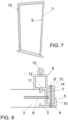
Figure 7 shows a view similar to that offigure 6 , but with the exterior frame already assembled. - Finally,
figure 8 shows a cross-sectional view of the assembly of the frame of the invention on the already existing frame and pre-frame. - In view of the referenced figures, it can be seen how the device of the invention is provided to facilitate the tasks of replacing a conventional gate (1) with a safety gate, for which it has been provided that, as shown
Figure 2 , once the original gate and its hinges have been removed (by cutting the same), its frame (2) is maintained, directly fixed to the work partition (3), so that it is not necessary to carry out work on said partition (3). - As can be seen in
Figure 3 , the frame of the invention is made up of two complementary parts, an interior frame (5) and an exterior frame (6) made of high-strength steel. - The interior frame (5) is obtained from Z-shaped profiles the three faces of which, orthogonal to one another, adapt externally to the profile of the frame (2) of the pre-existing gate, as shown in
figures 4 and5 , such that through its middle branch (7), and by drilling the corresponding hole, is fixed to said frame (2) by means of screws (8) that extend to the partition (3), in accordance with what is shown inFigure 8 , saidFigure 8 showing how said interior frame is flush with the interior edge of the pre-existing frame (2), so that it does not alter the gate opening. - According to another of the features of this interior frame (5), its internal end branch (9) ends in a bend (10) that can have different lengths, as well as be cut to size on site, determining a groove into which one of the ends of the exterior frame (6) is inserted and abuts, as described below.
- More specifically, the exterior frame (6) is obtained from profiles having an open U-shaped rectangular configuration, that is, one of the branches of which includes an interior bend (11) that abuts against the external free branch (12) of the interior frame (5), as shown in
figure 8 , while its other branch is externally bent defining an intermediate section (13) parallel to the gate, which is angled again in the opposite direction to define an end branch (14) perpendicular to the gate which fits and abuts against the interior wall or internal end branch (9) of the groove defined by the bend (10) of the interior frame (5). - In this way, and as shown in
figures 6 and7 , the exterior frame (6) is presented and fits on the interior frame (5) to be subsequently screwed thereto by means of through screws (8') through the intermediate section (13) of the exterior frame (6) and through the internal end branch (9) of the interior frame (5), as shown in the cross section offigure 8 . - Both the end branch (14) of the exterior frame (6), and the bend (10) of the interior frame (5) are susceptible to incorporating markings for cutting to size at 20mm, 30mm, etc., on site in order to adapt to the different thickness of existing partitions.
- As previously stated, the exterior frame (6) includes the corresponding hinges (15) integrated into one of the vertical uprights thereof, as well as the holes for the lock of the safety gate in the opposite upright, so that it can be quickly and easily installed once the interior frame and exterior frame are installed, in minimal time.
- In this way, a frame for safety gates is achieved that is easily installed on existing gates, that does not modify its opening, as it is flush with the pre-existing frame, which does not require modifying said frame, and that is adaptable to the different thickness of existing partitions.
Claims (4)
- A quick-installation frame for safety gates, which, being designed to be mounted on the frame (2) of a pre-existing gate once the gate and the hinges thereof have been removed, is characterised in that it is made from two complementary parts, an interior frame (5) and an exterior frame (6), wherein:a) The interior frame (5) is obtained from Z-shaped profiles the three faces of which, orthogonal to one another, adapt externally to the profile of the frame (2) of the pre-existing gate, being fixed thereto by means of through screws (8) through its middle branch (7), profile wherein its internal end branch (9) ends in a bend (10) determining a groove for receiving the exterior frame (6), bend (10) which when mounted on the frame (2) is flush with the internal edge of said frame (2), without modifying the gate opening,b) The exterior frame (6) is obtained from profiles having an open U-shaped rectangular configuration, one of the branches of which includes an interior bend (11) that abuts against the external free branch (12) of the interior frame (5), while its other branch is externally bent defining an intermediate section (13) parallel to the gate, which is bent again in the opposite direction to define an end branch (14) perpendicular to the gate, which fits and abuts against the interior wall or internal end branch (9) of the groove defined by the bend (10) of the interior frame (5),c) The exterior frame (6) is screwed to the interior frame (5) using through screws (8') through the intermediate section (13) of the exterior frame (6) and through the internal end branch (9) of the interior frame (5).
- The quick installation frame for safety gates, according to claim 1, characterised in that the exterior frame (6) includes hinges (15) integrated into one of the vertical uprights thereof, as well as the holes for the lock of the safety gate on the opposite upright.
- The quick installation frame for safety gates, according to claim 1, characterised in that both the interior frame (5) and the exterior frame (6) are made of high-strength steel.
- The quick installation frame for safety gates, according to claim 1, characterised in that both the end branch (14) of the exterior frame (6) and the bend (10) of the interior frame (5) are capable of incorporating markings for cutting to size on site depending on the thickness of the existing partition.
Applications Claiming Priority (1)
| Application Number | Priority Date | Filing Date | Title |
|---|---|---|---|
| ES202330485A ES2947864B2 (en) | 2023-06-09 | 2023-06-09 | QUICK INSTALLATION SECURITY DOOR FRAME |
Publications (3)
| Publication Number | Publication Date |
|---|---|
| EP4474606A1 true EP4474606A1 (en) | 2024-12-11 |
| EP4474606B1 EP4474606B1 (en) | 2026-01-14 |
| EP4474606C0 EP4474606C0 (en) | 2026-01-14 |
Family
ID=87576226
Family Applications (1)
| Application Number | Title | Priority Date | Filing Date |
|---|---|---|---|
| EP24180004.4A Active EP4474606B1 (en) | 2023-06-09 | 2024-06-04 | Quick installation frame for security doors |
Country Status (2)
| Country | Link |
|---|---|
| EP (1) | EP4474606B1 (en) |
| ES (1) | ES2947864B2 (en) |
Citations (5)
| Publication number | Priority date | Publication date | Assignee | Title |
|---|---|---|---|---|
| FR2701286A1 (en) * | 1993-02-08 | 1994-08-12 | Decayeux Ets | Mounted door jamb, comprising improved fire-resistant (fire-retarding) means |
| DE29913772U1 (en) * | 1999-08-06 | 2000-02-03 | Biergans, Günther, 64859 Eppertshausen | Durasafe retrofit frame |
| US20030046886A1 (en) | 2001-09-07 | 2003-03-13 | Potts Thomas Lee | Split jamb for doors and windows |
| ES1074382U (en) | 2010-11-30 | 2011-04-25 | Hilario Ortiz Gutierrez | Articulated frame for assembling reinforced doors. (Machine-translation by Google Translate, not legally binding) |
| ES1078556U (en) | 2013-01-18 | 2013-02-07 | Rubio Carpintería Metálica Y Cerrajería , S. L. | Frame for doors (Machine-translation by Google Translate, not legally binding) |
Family Cites Families (4)
| Publication number | Priority date | Publication date | Assignee | Title |
|---|---|---|---|---|
| JPS60117983U (en) * | 1984-01-20 | 1985-08-09 | 三井軽金属加工株式会社 | replacement door |
| JP3634776B2 (en) * | 2001-07-26 | 2005-03-30 | 株式会社アイ・エス | Simple renovated door using existing door frame |
| JP2004027590A (en) * | 2002-06-25 | 2004-01-29 | Kenji Tsuru | Door body installing structure |
| JP5118535B2 (en) * | 2008-03-31 | 2013-01-16 | フジメタル株式会社 | Partially refurbished door frame and its refurbishing method |
-
2023
- 2023-06-09 ES ES202330485A patent/ES2947864B2/en active Active
-
2024
- 2024-06-04 EP EP24180004.4A patent/EP4474606B1/en active Active
Patent Citations (5)
| Publication number | Priority date | Publication date | Assignee | Title |
|---|---|---|---|---|
| FR2701286A1 (en) * | 1993-02-08 | 1994-08-12 | Decayeux Ets | Mounted door jamb, comprising improved fire-resistant (fire-retarding) means |
| DE29913772U1 (en) * | 1999-08-06 | 2000-02-03 | Biergans, Günther, 64859 Eppertshausen | Durasafe retrofit frame |
| US20030046886A1 (en) | 2001-09-07 | 2003-03-13 | Potts Thomas Lee | Split jamb for doors and windows |
| ES1074382U (en) | 2010-11-30 | 2011-04-25 | Hilario Ortiz Gutierrez | Articulated frame for assembling reinforced doors. (Machine-translation by Google Translate, not legally binding) |
| ES1078556U (en) | 2013-01-18 | 2013-02-07 | Rubio Carpintería Metálica Y Cerrajería , S. L. | Frame for doors (Machine-translation by Google Translate, not legally binding) |
Also Published As
| Publication number | Publication date |
|---|---|
| ES2947864A1 (en) | 2023-08-23 |
| EP4474606B1 (en) | 2026-01-14 |
| ES2947864B2 (en) | 2024-01-02 |
| EP4474606C0 (en) | 2026-01-14 |
Similar Documents
| Publication | Publication Date | Title |
|---|---|---|
| US5070650A (en) | Door jamb reinforcing apparatus | |
| EP2217784B1 (en) | Apparatus and method for installing windows in timber frame construction | |
| DE19501101A1 (en) | Interconnected posts and transoms formed from profiled bars | |
| DE202007004060U1 (en) | Closing-off device for gap in building has inner frame profile positively coupled to connecting profile which is itself connected to outer frame profile | |
| EP4474606B1 (en) | Quick installation frame for security doors | |
| DE2003009A1 (en) | Door frame | |
| DE4444327A1 (en) | Steel door frame, preferably for use in renovation of old buildings | |
| EP0725202B1 (en) | Reinforcement for doors or windows | |
| EP4006291B1 (en) | Frame and window element with compression insert | |
| DE19744832A1 (en) | Window frame installation system | |
| WO2000032898A1 (en) | Method for fixing a frame by means of a mounting case | |
| EP3258047A1 (en) | Method for producing a prefabricated element for a building, prefabricated element, frame and method for fixing a window frame to a frame connected to a wall element | |
| EP2789784A1 (en) | Building termination in explosive inhibiting design with wire rope loop fixing | |
| EP3441557B1 (en) | Gate system comprising a door system | |
| EP0082338B1 (en) | Compound window | |
| EP4202170B1 (en) | Connector, butt joint, and method for manufacturing same | |
| DE102005043079A1 (en) | window | |
| CN218881680U (en) | Elevator protective door | |
| EP1015724A1 (en) | Three-piece metal door case | |
| DE102005001625B4 (en) | profile | |
| DE10043965A1 (en) | Frame profile for holding a door or window has an overlap off-set at the side parallel to building structure and with protruding profiled strip on same side at right angles to overlap | |
| DE102011075832A1 (en) | Door with a door opening bounded by supports | |
| EP4006290A1 (en) | Window element and method for mounting a window | |
| DE3425444A1 (en) | Fastening element for window and door frames made of plastic and aluminium profiles, which can be inserted into masonry openings | |
| EP3674508A1 (en) | Built-in element, door system comprising a built-in element and method for assembling a built-in element |
Legal Events
| Date | Code | Title | Description |
|---|---|---|---|
| PUAI | Public reference made under article 153(3) epc to a published international application that has entered the european phase |
Free format text: ORIGINAL CODE: 0009012 |
|
| STAA | Information on the status of an ep patent application or granted ep patent |
Free format text: STATUS: THE APPLICATION HAS BEEN PUBLISHED |
|
| AK | Designated contracting states |
Kind code of ref document: A1 Designated state(s): AL AT BE BG CH CY CZ DE DK EE ES FI FR GB GR HR HU IE IS IT LI LT LU LV MC ME MK MT NL NO PL PT RO RS SE SI SK SM TR |
|
| STAA | Information on the status of an ep patent application or granted ep patent |
Free format text: STATUS: REQUEST FOR EXAMINATION WAS MADE |
|
| 17P | Request for examination filed |
Effective date: 20240605 |
|
| REG | Reference to a national code |
Ref country code: DE Ref legal event code: R079 Free format text: PREVIOUS MAIN CLASS: E06B0001340000 Ipc: E06B0001600000 Ref document number: 602024002027 Country of ref document: DE |
|
| GRAP | Despatch of communication of intention to grant a patent |
Free format text: ORIGINAL CODE: EPIDOSNIGR1 |
|
| STAA | Information on the status of an ep patent application or granted ep patent |
Free format text: STATUS: GRANT OF PATENT IS INTENDED |
|
| RIC1 | Information provided on ipc code assigned before grant |
Ipc: E06B 5/11 20060101ALI20250506BHEP Ipc: E06B 1/20 20060101ALI20250506BHEP Ipc: E06B 1/34 20060101ALI20250506BHEP Ipc: E06B 1/60 20060101AFI20250506BHEP |
|
| INTG | Intention to grant announced |
Effective date: 20250602 |
|
| GRAS | Grant fee paid |
Free format text: ORIGINAL CODE: EPIDOSNIGR3 |
|
| GRAA | (expected) grant |
Free format text: ORIGINAL CODE: 0009210 |
|
| STAA | Information on the status of an ep patent application or granted ep patent |
Free format text: STATUS: THE PATENT HAS BEEN GRANTED |
|
| AK | Designated contracting states |
Kind code of ref document: B1 Designated state(s): AL AT BE BG CH CY CZ DE DK EE ES FI FR GB GR HR HU IE IS IT LI LT LU LV MC ME MK MT NL NO PL PT RO RS SE SI SK SM TR |
|
| REG | Reference to a national code |
Ref country code: CH Ref legal event code: F10 Free format text: ST27 STATUS EVENT CODE: U-0-0-F10-F00 (AS PROVIDED BY THE NATIONAL OFFICE) Effective date: 20260114 Ref country code: GB Ref legal event code: FG4D |
|
| REG | Reference to a national code |
Ref country code: DE Ref legal event code: R096 Ref document number: 602024002027 Country of ref document: DE |
|
| REG | Reference to a national code |
Ref country code: IE Ref legal event code: FG4D |
|
| U01 | Request for unitary effect filed |
Effective date: 20260115 |
|
| U07 | Unitary effect registered |
Designated state(s): AT BE BG DE DK EE FI FR IT LT LU LV MT NL PT RO SE SI Effective date: 20260122 |