EP4474580A2 - Procédé d'installation d'un monopieu dans un fond marin à l'aide d'une barge ou d'un navire de transport - Google Patents
Procédé d'installation d'un monopieu dans un fond marin à l'aide d'une barge ou d'un navire de transport Download PDFInfo
- Publication number
- EP4474580A2 EP4474580A2 EP24206933.4A EP24206933A EP4474580A2 EP 4474580 A2 EP4474580 A2 EP 4474580A2 EP 24206933 A EP24206933 A EP 24206933A EP 4474580 A2 EP4474580 A2 EP 4474580A2
- Authority
- EP
- European Patent Office
- Prior art keywords
- monopile
- chamber
- air
- tool
- internal volume
- Prior art date
- Legal status (The legal status is an assumption and is not a legal conclusion. Google has not performed a legal analysis and makes no representation as to the accuracy of the status listed.)
- Pending
Links
Images






Classifications
-
- E—FIXED CONSTRUCTIONS
- E02—HYDRAULIC ENGINEERING; FOUNDATIONS; SOIL SHIFTING
- E02D—FOUNDATIONS; EXCAVATIONS; EMBANKMENTS; UNDERGROUND OR UNDERWATER STRUCTURES
- E02D7/00—Methods or apparatus for placing sheet pile bulkheads, piles, mouldpipes, or other moulds
- E02D7/02—Placing by driving
- E02D7/06—Power-driven drivers
-
- B—PERFORMING OPERATIONS; TRANSPORTING
- B63—SHIPS OR OTHER WATERBORNE VESSELS; RELATED EQUIPMENT
- B63B—SHIPS OR OTHER WATERBORNE VESSELS; EQUIPMENT FOR SHIPPING
- B63B77/00—Transporting or installing offshore structures on site using buoyancy forces, e.g. using semi-submersible barges, ballasting the structure or transporting of oil-and-gas platforms
- B63B77/10—Transporting or installing offshore structures on site using buoyancy forces, e.g. using semi-submersible barges, ballasting the structure or transporting of oil-and-gas platforms specially adapted for electric power plants, e.g. wind turbines or tidal turbine generators
-
- B—PERFORMING OPERATIONS; TRANSPORTING
- B63—SHIPS OR OTHER WATERBORNE VESSELS; RELATED EQUIPMENT
- B63B—SHIPS OR OTHER WATERBORNE VESSELS; EQUIPMENT FOR SHIPPING
- B63B27/00—Arrangement of ship-based loading or unloading equipment for cargo or passengers
- B63B27/10—Arrangement of ship-based loading or unloading equipment for cargo or passengers of cranes
-
- B—PERFORMING OPERATIONS; TRANSPORTING
- B63—SHIPS OR OTHER WATERBORNE VESSELS; RELATED EQUIPMENT
- B63B—SHIPS OR OTHER WATERBORNE VESSELS; EQUIPMENT FOR SHIPPING
- B63B35/00—Vessels or similar floating structures specially adapted for specific purposes and not otherwise provided for
- B63B35/003—Vessels or similar floating structures specially adapted for specific purposes and not otherwise provided for for transporting very large loads, e.g. offshore structure modules
-
- B—PERFORMING OPERATIONS; TRANSPORTING
- B63—SHIPS OR OTHER WATERBORNE VESSELS; RELATED EQUIPMENT
- B63B—SHIPS OR OTHER WATERBORNE VESSELS; EQUIPMENT FOR SHIPPING
- B63B77/00—Transporting or installing offshore structures on site using buoyancy forces, e.g. using semi-submersible barges, ballasting the structure or transporting of oil-and-gas platforms
-
- E—FIXED CONSTRUCTIONS
- E02—HYDRAULIC ENGINEERING; FOUNDATIONS; SOIL SHIFTING
- E02D—FOUNDATIONS; EXCAVATIONS; EMBANKMENTS; UNDERGROUND OR UNDERWATER STRUCTURES
- E02D13/00—Accessories for placing or removing piles or bulkheads, e.g. noise attenuating chambers
-
- E—FIXED CONSTRUCTIONS
- E02—HYDRAULIC ENGINEERING; FOUNDATIONS; SOIL SHIFTING
- E02D—FOUNDATIONS; EXCAVATIONS; EMBANKMENTS; UNDERGROUND OR UNDERWATER STRUCTURES
- E02D27/00—Foundations as substructures
- E02D27/32—Foundations for special purposes
- E02D27/52—Submerged foundations, i.e. submerged in open water
- E02D27/525—Submerged foundations, i.e. submerged in open water using elements penetrating the underwater ground
-
- E—FIXED CONSTRUCTIONS
- E02—HYDRAULIC ENGINEERING; FOUNDATIONS; SOIL SHIFTING
- E02D—FOUNDATIONS; EXCAVATIONS; EMBANKMENTS; UNDERGROUND OR UNDERWATER STRUCTURES
- E02D5/00—Bulkheads, piles, or other structural elements specially adapted to foundation engineering
- E02D5/22—Piles
- E02D5/24—Prefabricated piles
-
- F—MECHANICAL ENGINEERING; LIGHTING; HEATING; WEAPONS; BLASTING
- F03—MACHINES OR ENGINES FOR LIQUIDS; WIND, SPRING, OR WEIGHT MOTORS; PRODUCING MECHANICAL POWER OR A REACTIVE PROPULSIVE THRUST, NOT OTHERWISE PROVIDED FOR
- F03D—WIND MOTORS
- F03D13/00—Assembly, mounting or commissioning of wind motors; Arrangements specially adapted for transporting wind motor components
- F03D13/10—Assembly of wind motors; Arrangements for erecting wind motors
- F03D13/112—Assembly of wind motors; Arrangements for erecting wind motors of towers; of masts
-
- F—MECHANICAL ENGINEERING; LIGHTING; HEATING; WEAPONS; BLASTING
- F03—MACHINES OR ENGINES FOR LIQUIDS; WIND, SPRING, OR WEIGHT MOTORS; PRODUCING MECHANICAL POWER OR A REACTIVE PROPULSIVE THRUST, NOT OTHERWISE PROVIDED FOR
- F03D—WIND MOTORS
- F03D13/00—Assembly, mounting or commissioning of wind motors; Arrangements specially adapted for transporting wind motor components
- F03D13/10—Assembly of wind motors; Arrangements for erecting wind motors
- F03D13/126—Offshore
-
- F—MECHANICAL ENGINEERING; LIGHTING; HEATING; WEAPONS; BLASTING
- F03—MACHINES OR ENGINES FOR LIQUIDS; WIND, SPRING, OR WEIGHT MOTORS; PRODUCING MECHANICAL POWER OR A REACTIVE PROPULSIVE THRUST, NOT OTHERWISE PROVIDED FOR
- F03D—WIND MOTORS
- F03D13/00—Assembly, mounting or commissioning of wind motors; Arrangements specially adapted for transporting wind motor components
- F03D13/10—Assembly of wind motors; Arrangements for erecting wind motors
- F03D13/139—Assembling or erecting wind motors by using lifting means
-
- F—MECHANICAL ENGINEERING; LIGHTING; HEATING; WEAPONS; BLASTING
- F03—MACHINES OR ENGINES FOR LIQUIDS; WIND, SPRING, OR WEIGHT MOTORS; PRODUCING MECHANICAL POWER OR A REACTIVE PROPULSIVE THRUST, NOT OTHERWISE PROVIDED FOR
- F03D—WIND MOTORS
- F03D13/00—Assembly, mounting or commissioning of wind motors; Arrangements specially adapted for transporting wind motor components
- F03D13/20—Arrangements for mounting or supporting wind motors; Masts or towers for wind motors
- F03D13/25—Arrangements for mounting or supporting wind motors; Masts or towers for wind motors specially adapted for offshore installation
-
- E—FIXED CONSTRUCTIONS
- E02—HYDRAULIC ENGINEERING; FOUNDATIONS; SOIL SHIFTING
- E02B—HYDRAULIC ENGINEERING
- E02B17/00—Artificial islands mounted on piles or like supports, e.g. platforms on raisable legs or offshore constructions; Construction methods therefor
- E02B2017/0039—Methods for placing the offshore structure
- E02B2017/0047—Methods for placing the offshore structure using a barge
-
- E—FIXED CONSTRUCTIONS
- E02—HYDRAULIC ENGINEERING; FOUNDATIONS; SOIL SHIFTING
- E02B—HYDRAULIC ENGINEERING
- E02B17/00—Artificial islands mounted on piles or like supports, e.g. platforms on raisable legs or offshore constructions; Construction methods therefor
- E02B2017/0056—Platforms with supporting legs
- E02B2017/0065—Monopile structures
-
- E—FIXED CONSTRUCTIONS
- E02—HYDRAULIC ENGINEERING; FOUNDATIONS; SOIL SHIFTING
- E02B—HYDRAULIC ENGINEERING
- E02B17/00—Artificial islands mounted on piles or like supports, e.g. platforms on raisable legs or offshore constructions; Construction methods therefor
- E02B2017/0091—Offshore structures for wind turbines
-
- E—FIXED CONSTRUCTIONS
- E02—HYDRAULIC ENGINEERING; FOUNDATIONS; SOIL SHIFTING
- E02D—FOUNDATIONS; EXCAVATIONS; EMBANKMENTS; UNDERGROUND OR UNDERWATER STRUCTURES
- E02D13/00—Accessories for placing or removing piles or bulkheads, e.g. noise attenuating chambers
- E02D13/04—Guide devices; Guide frames
-
- F—MECHANICAL ENGINEERING; LIGHTING; HEATING; WEAPONS; BLASTING
- F05—INDEXING SCHEMES RELATING TO ENGINES OR PUMPS IN VARIOUS SUBCLASSES OF CLASSES F01-F04
- F05B—INDEXING SCHEME RELATING TO WIND, SPRING, WEIGHT, INERTIA OR LIKE MOTORS, TO MACHINES OR ENGINES FOR LIQUIDS COVERED BY SUBCLASSES F03B, F03D AND F03G
- F05B2230/00—Manufacture
- F05B2230/60—Assembly methods
- F05B2230/61—Assembly methods using auxiliary equipment for lifting or holding
- F05B2230/6102—Assembly methods using auxiliary equipment for lifting or holding carried on a floating platform
-
- F—MECHANICAL ENGINEERING; LIGHTING; HEATING; WEAPONS; BLASTING
- F05—INDEXING SCHEMES RELATING TO ENGINES OR PUMPS IN VARIOUS SUBCLASSES OF CLASSES F01-F04
- F05B—INDEXING SCHEME RELATING TO WIND, SPRING, WEIGHT, INERTIA OR LIKE MOTORS, TO MACHINES OR ENGINES FOR LIQUIDS COVERED BY SUBCLASSES F03B, F03D AND F03G
- F05B2240/00—Components
- F05B2240/90—Mounting on supporting structures or systems
- F05B2240/95—Mounting on supporting structures or systems offshore
-
- F—MECHANICAL ENGINEERING; LIGHTING; HEATING; WEAPONS; BLASTING
- F05—INDEXING SCHEMES RELATING TO ENGINES OR PUMPS IN VARIOUS SUBCLASSES OF CLASSES F01-F04
- F05B—INDEXING SCHEME RELATING TO WIND, SPRING, WEIGHT, INERTIA OR LIKE MOTORS, TO MACHINES OR ENGINES FOR LIQUIDS COVERED BY SUBCLASSES F03B, F03D AND F03G
- F05B2240/00—Components
- F05B2240/90—Mounting on supporting structures or systems
- F05B2240/97—Mounting on supporting structures or systems on a submerged structure
-
- Y—GENERAL TAGGING OF NEW TECHNOLOGICAL DEVELOPMENTS; GENERAL TAGGING OF CROSS-SECTIONAL TECHNOLOGIES SPANNING OVER SEVERAL SECTIONS OF THE IPC; TECHNICAL SUBJECTS COVERED BY FORMER USPC CROSS-REFERENCE ART COLLECTIONS [XRACs] AND DIGESTS
- Y02—TECHNOLOGIES OR APPLICATIONS FOR MITIGATION OR ADAPTATION AGAINST CLIMATE CHANGE
- Y02E—REDUCTION OF GREENHOUSE GAS [GHG] EMISSIONS, RELATED TO ENERGY GENERATION, TRANSMISSION OR DISTRIBUTION
- Y02E10/00—Energy generation through renewable energy sources
- Y02E10/70—Wind energy
- Y02E10/727—Offshore wind turbines
Definitions
- the present invention deals with a method of installing a monopile in a seabed at an installation location, comprising: charging the monopile on a transportation barge or vessel, lifting a longitudinal extremity of the monopile using a crane mounted on a heavy lift vessel or on a jack-up platform, disengaging the monopile from the transportation barge or vessel, and lowering the monopile with respect to the barge and hammering the monopile into the seabed.
- Such monopile may serve as a support for an offshore wind mill.
- Monopiles are huge steel structures, with a length up to 95 meters and more, including up to 50 meters in the seabed, and an external diameter up to 8 meters and more. Their mass may amount to 2000 metric tonnes or more.
- At least one monopile is loaded on a regular transportation barge in a horizontal storage position.
- This regular transportation barge is carried near a heavy lift vessel or a jack-up platform located near the installation location.
- the monopile is lifted and carried from the regular transportation barge to an upending barge or vessel having a tiltable upending tool, the monopile remaining approximately horizontal during carrying.
- the upending tool is tilted to put the monopile in a vertical position, wherein the monopile is partly immersed.
- the monopile is then disengaged from the upending tool, lowered and hammered into the seabed.
- Such a process works well. However, it comprises many steps that are complex, due to the dimensions and mass of the monopile and as they are performed offshore. Also, the crane used to carry the monopile from the regular transportation barge to the upending barge or vessel has to withstand the full weight of the monopile, plus dynamic efforts due to relative movements of the monopile being carried. This is also time-consuming in crane revolving mode as subsequent ballasting operations are required in the meantime. As a consequence, such a crane is a huge, expensive piece of equipment.
- An aim of the invention is thus to reduce the cost of installing the monopile.
- the invention proposes a method of installing a monopile in a seabed at an installation location, comprising:
- the method comprises one or several of the following features, taken in isolation or any technically feasible combination:
- the invention also deals with an assembly comprising:
- the methods aims at installing a monopile 10 (shown in Figures 1-6 and 8 ) in a seabed 12 at an installation location 14 ( Figure 8 ).
- the method comprises charging the monopile 10 on a transportation barge 16 in a harbor 18 ( Figure 1 ), the transportation barge having a main body 20, and an upending tool 22 mounted rotatable on the main body around a horizontal axis R, the monopile and the upending tool being in a transport position ( Figure 2 ).
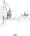
- the method comprises moving the transportation barge 16 from the harbor 18 to a vicinity of the installation location 14 ( Figure 3 ), rotating the monopile 10 and the upending tool 22 together ( Figure 4 ) from the transport position to a discharge position ( Figure 5 ), and disengaging the monopile 10 from the upending tool 22.
- the method comprises lowering the monopile 10 with respect to the transportation barge 16 ( Figure 6 ) and hammering the monopile 10 into the seabed 12 ( Figure 8 ).
- the monopile 10 defines a longitudinal axis L.
- the monopile 10 has a length L1 for example comprised between 60 and 100 meters, and a maximum external diameter D1 for example comprised between 7 and 12 meters.
- the monopile mass is for example comprised between 700 and 2000 tonnes.
- the monopile 10 has a first longitudinal extremity 24 adapted to be pushed into the seabed 12, so that the monopile can for example serve as a support for a wind mill (not shown), the longitudinal axis L being vertical.
- the monopile 10 Once the monopile 10 is installed, it has a second longitudinal extremity 26, opposite the first longitudinal extremity 24, still above a body of water 28, on which the wind mill can be fixed.
- the monopile 10 for example comprises an external envelope 30 around the longitudinal axis L, the external envelope defining an internal volume 32 of the monopile.
- the transportation barge 16 is for example near a quay 34 of the harbor 18. Charging is for example performed using at least one crane 36 located on the quay 34.
- the monopile 10 is for example carried in a horizontal position, in which the crane 36 withstands a full weight of the monopile, and deposited on the upending tool 22.
- charging is performed using a sheer leg (i.e. a pier floating crane), a heavy lift vessel available locally, or alternatively with self-propelled modular trailers from quay 34 to barge 16.
- a sheer leg i.e. a pier floating crane
- a heavy lift vessel available locally, or alternatively with self-propelled modular trailers from quay 34 to barge 16.
- the monopile 10 rests on a cradle 38 of the upending tool 22 and is for example approximately horizontal.
- the upending tool 22 is advantageously mounted on a support structure 40 of the transportation barge 16.
- the upending tool 22 comprises a bottom part 42 located near the first longitudinal extremity 24 of the monopile 10, and advantageously two longitudinal telescopic beams 44, 46 located on either sides of the monopile along the horizontal axis R.
- the bottom part 42 advantageously extends between distal extremities 48, 50 of the telescopic beams 44, 46.
- the bottom part 42 is for example perpendicular to the longitudinal axis L in the transport position.
- the cradle 38 of the upending tool 22 partly surrounds the monopile 10 around the longitudinal axis L ( Figure 2 ), the cradle being under the monopile.
- the cradle 38 is semicircular.
- the upending tool 22 comprises one or several other cradles, for example analogous to the cradle 38.
- the cradle 38 and the other cradles are distributed along the longitudinal direction L and support the monopile 10 in the transport position.
- a transportation vessel is used instead of the transportation barge 16.
- a transportation vessel is self-propelled, whereas a transportation barge is not, and therefore is towed by a tug boat (not shown).
- a tug or vessel (not shown) is used for moving the transportation barge 16 from the harbor 18 towards the installation location 14 in case the transportation barge 16 is not self-propelled.
- the transportation barge 16 is then located near a heavy lift vessel 52.
- the transportation barge 16 is located near a jack-up platform equipped with a lifting crane.
- the monopile Before rotating the monopile 10 and the upending tool 22 together ( Figure 4 ), the monopile is advantageously equipped at its second longitudinal extremity 26 with an internal lifting tool 54 shown in Figure 7 .
- the internal lifting tool 54 is adapted for being attached to a crane 56 mounted on the heavy lift vessel 52 (or a jack-up platform).
- the internal lifting tool 54 at least partly extends in the internal volume 32 of the monopile 10 and advantageously comprises a plurality of pads 58 ( Figure 7 ) distributed around the longitudinal axis L and adapted to press on a radially inner surface 60 of the envelope 30, so as to stick to the monopile thanks to shear friction.
- the internal lifting tool 54 for example comprises an air tight joint 62 extending around the longitudinal axis L and in contact with the envelope 30, and advantageously an air vent 64.
- Rotating the monopile 10 and the upending tool 22 is obtained by lifting the second longitudinal extremity 26 of the monopile. Therefore, the crane 56 is connected to the second longitudinal extremity 26, advantageously to the internal lifting tool 54, and pulls the monopile.
- the monopile 10 and the upending tool 22 rotate together around the axis R to come to the discharge position, in which the monopile is vertical and has its first longitudinal extremity 24 resting on the bottom part 42 of the upending tool 22.
- the monopile 10 is disengaged from the upending tool 22 and for example put in a gripper system 66 ( Figure 6 ) while it is being lowered with respect to the transportation barge 16 till the monopile 10 self penetrates and rests on the seabed 12.
- the monopile 10 is guided by the gripper system 66.
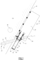
- the method comprises providing a chamber 70 containing an amount of air, the chamber 70 providing additional buoyancy to the monopile 10.
- the monopile 10 being partly immersed, receives a moderate buoyancy force due to the volume of the envelope 30 displacing water.
- the chamber 70 provides additional buoyancy because it displaces more water.
- the crane 56 does not have to withstand the full weight in air of the monopile 10.
- the crane 56 can have a maximum lifting capacity smaller than said full weight in air, and smaller than the weight of the monopile 10 in water without the chamber 70.
- said additional buoyancy amounts to several hundreds of tonnes, and advantageously more than 20% or even 30% of the monopile mass.
- the monopile mass is 2000 tonnes
- the additional buoyancy brought by the chamber 70 may reach 600 tonnes.
- the chamber 70 extends within the internal volume 32 and is delimited downwards by a surface of free water 72 located under a waterline 74 of the monopile.
- the internal lifting tool 54 forms an upper limit of the chamber 70, thanks to the air tight joint 62.
- the method comprises using a system 76 for adjusting the amount and the pressure of air in the chamber 70.
- the system 76 includes the air vent 64 of the internal lifting tool 54 for letting part of said amount of air exit from the chamber 70. This allows raising the surface of free water 72 with respect to said waterline 74, thereby decreasing the additional buoyancy brought by the chamber 70.
- the system 76 comprises at least one air pump 78 configured for injecting air into the chamber 70. This allows lowering the surface of free water 72 with respect to said waterline 74, thereby increasing the additional buoyancy brought by the chamber 70.
- the air pump 78 is preferably an air compressor, and more preferably a centrifugal one.
- the internal lifting tool 54 advantageously comprises an aperture, for example the air vent 64, for introducing compressed air provided by the air pump 78.
- centrifugal compressors are particularly preferred, since they allow high volume throughput with appropriate pressure, typically ranging from 0.5 to 5 barg.
- Barg stands for measured pressure in bar relative to the atmospheric pressure. For instance, if the atmospheric pressure is one bar and the pressure that is delivered at compressor outlet is 0,5 barg, then the absolute pressure at compressor outlet is 1,5 bar.
- Compressor outlet may provide compressed air through a pipe connected to the chamber 70, ideally through a dedicated aperture in the internal lifting tool 54 or through the air vent 64.
- the pipe diameter is adapted to the compressor capacity and the working pressure that has been selected based on the monopile size and a desired buoyancy during the installation. Buoyancy may be adapted at each step of the installation of the monopile. It is advisable to install at least one air valve on the pipe anywhere between the compressor outlet and the chamber 70.
- the monopile 10, the internal lifting tool 54 and the chamber 70 form an assembly 80 according to the invention.
- the monopile 10 is installed on the transportation barge 16 (or on a vessel) on the upending tool 22 in a harbor 18 and not in the vicinity of the installation location 14, the number of steps performed offshore is reduced.
- the crane 56 can have a maximum lifting capacity smaller than the full weight in air of the monopile 10. Such a crane is much less expensive, as there are more potential providers.
- the optional step of providing a chamber 70 containing air further reduces the maximum lifting capacity that is needed. Besides, such a chamber 70 is for example easily obtained using the internal lifting tool 54 as an upper limit.
- the installation schedule can be improved at equivalent installation cost by mobilizing several low cost heavy lift vessels or jack-up platforms rather than one more expensive.
- the above described method makes it possible to use jack-up platforms which usually have lower craneage than large heavy lift vessels.
- the method allows installing large monopiles in shallow waters, as jack-up platforms have limited draft and can access shallow waters, which is not the case for heavy lift vessels.
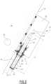
- the chamber 70 extends within the internal volume 32, and is delimited downwards by a sacrificial membrane 82 or a diaphragm fixed on a lower end 84 of the monopile 10.
- the chamber 70 is not delimited by a surface of free water in fluid communication with the body of water 28.
- the membrane 82 surrounds the lower end 84 around the longitudinal direction L.
- the membrane 82 is watertight. When the monopile 10 is partly immersed in the body of water 28, the envelope 30 and the membrane 82 work as a hull defining the chamber 70.
- the membrane 82 is called "sacrificial", as it can be torn apart when the monopile 10 penetrates into the seabed 12.
- the amount of air in the chamber 70 may be reduced by allowing some water to flow in it in between the membrane 82 and the envelope 30 or by pumping water in (towards) the chamber 70.
- the internal lifting tool 54 if present, does not have to be air tight.
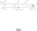
- the chamber 70 comprises an inflatable member 86 located in the internal volume 32 and attached to the monopile 10.
- the inflatable member 86 is attached to the first longitudinal extremity 24 of the monopile by peripheral hooks 88.
- the inflatable member 86 When inflated with air, the inflatable member 86 operates as an "underwater lifting parachute", the monopile 10 being partly immersed. Water from the body of water 28 can freely circulate around the inflatable member 86.
- the amount of air in the inflatable member 86, hence buoyancy, can advantageously be adjusted.
- the inflatable member 86 is advantageously connected towards the second longitudinal extremity 26 by a link 90 allowing to help deploying the inflatable member 86 in the internal volume 32 and/or connecting the inflatable member to an air source, for example the pump 78 shown in Figure 7 .
- the inflatable member 86 is advantageously recovered before the monopile 10 penetrates into the seabed 12.
- the internal lifting tool 54 if present, does not have to be air tight, but could be, so as to provide additional buoyancy.
- An air compressor such as the ones described above, may be used to inflate the inflatable member 86, possibly via the internal lifting tool 54.
- the chamber 70 is delimited downwards by an inflatable plugging element 92 located in the internal volume 32 and pressing against the envelope 30.
- the chamber 70 comprises the plugging element 92, and advantageously a part 94 of the internal volume 32 located above the plugging element 92 when the monopile 10 is in the discharge position.
- the plugging element 92 maintains itself in a given longitudinal position with respect to the envelope 30 by friction, and advantageously prevents water from invading the part 94.
- the longitudinal position can advantageously be selected before inflating the plugging element 92, which allows adjusting the additional buoyancy.
- two positions are represented.
- the plugging element 92 is advantageously recovered before the monopile 10 penetrated into the seabed 12.
- the internal lifting tool 54 if present, does not have to be air tight.
- An air compressor such as the ones described above, may be used to inflate the plugging element 92, possibly via the internal lifting tool 54.
- the external envelope 32 may define an orifice 96 intended to form a passage for at least one electric cable 98 (shown in Figure 8 ) from the internal volume 32 towards outside the monopile 10.
- Such a cable is for example used to electrically connect a wind turbine (not shown) fixed to the monopile 10 to a network (not shown), once the monopile is installed (even if, for simplicity, the cable is shown in Figure 8 , in which the monopile is not yet installed).
- the passage is intended to be located above the seabed 12 once the monopile 10 is installed.
- the method and its variants, in particular the first and third ones, may further comprise closing the orifice 96 with a temporary closing member 100, such as a plugging pin device, while the monopile 10 is being installed, in order to prevent water from flowing into the chamber 70.
- a temporary closing member 100 such as a plugging pin device
- the longitudinal position of the plugging element 92 can advantageously be chosen such that the plugging element actually forms the closing member 100.
- the cable 98 can be installed via the orifice 96.
Landscapes
- Engineering & Computer Science (AREA)
- Mechanical Engineering (AREA)
- Chemical & Material Sciences (AREA)
- Combustion & Propulsion (AREA)
- Life Sciences & Earth Sciences (AREA)
- General Engineering & Computer Science (AREA)
- Ocean & Marine Engineering (AREA)
- Sustainable Energy (AREA)
- Sustainable Development (AREA)
- Structural Engineering (AREA)
- Transportation (AREA)
- Civil Engineering (AREA)
- Paleontology (AREA)
- Mining & Mineral Resources (AREA)
- General Life Sciences & Earth Sciences (AREA)
- Underground Or Underwater Handling Of Building Materials (AREA)
Applications Claiming Priority (3)
| Application Number | Priority Date | Filing Date | Title |
|---|---|---|---|
| EP22305322 | 2022-03-18 | ||
| EP23712230.4A EP4359297B1 (fr) | 2022-03-18 | 2023-03-17 | Méthode d'installation d'un pilier sur fond marin utilisant une barge de transport ou un vaisseau |
| PCT/EP2023/056864 WO2023175131A1 (fr) | 2022-03-18 | 2023-03-17 | Procédé d'installation d'un monopieu dans un fond marin à l'aide d'une barge ou d'un navire de transport |
Related Parent Applications (2)
| Application Number | Title | Priority Date | Filing Date |
|---|---|---|---|
| EP23712230.4A Division EP4359297B1 (fr) | 2022-03-18 | 2023-03-17 | Méthode d'installation d'un pilier sur fond marin utilisant une barge de transport ou un vaisseau |
| EP23712230.4A Division-Into EP4359297B1 (fr) | 2022-03-18 | 2023-03-17 | Méthode d'installation d'un pilier sur fond marin utilisant une barge de transport ou un vaisseau |
Publications (2)
| Publication Number | Publication Date |
|---|---|
| EP4474580A2 true EP4474580A2 (fr) | 2024-12-11 |
| EP4474580A3 EP4474580A3 (fr) | 2025-01-01 |
Family
ID=80999109
Family Applications (2)
| Application Number | Title | Priority Date | Filing Date |
|---|---|---|---|
| EP24206933.4A Pending EP4474580A3 (fr) | 2022-03-18 | 2023-03-17 | Procédé d'installation d'un monopieu dans un fond marin à l'aide d'une barge ou d'un navire de transport |
| EP23712230.4A Active EP4359297B1 (fr) | 2022-03-18 | 2023-03-17 | Méthode d'installation d'un pilier sur fond marin utilisant une barge de transport ou un vaisseau |
Family Applications After (1)
| Application Number | Title | Priority Date | Filing Date |
|---|---|---|---|
| EP23712230.4A Active EP4359297B1 (fr) | 2022-03-18 | 2023-03-17 | Méthode d'installation d'un pilier sur fond marin utilisant une barge de transport ou un vaisseau |
Country Status (6)
| Country | Link |
|---|---|
| US (1) | US20250179753A1 (fr) |
| EP (2) | EP4474580A3 (fr) |
| KR (1) | KR20240161817A (fr) |
| DK (1) | DK4359297T3 (fr) |
| PL (1) | PL4359297T3 (fr) |
| WO (1) | WO2023175131A1 (fr) |
Families Citing this family (3)
| Publication number | Priority date | Publication date | Assignee | Title |
|---|---|---|---|---|
| NL2036032B1 (en) * | 2023-10-13 | 2025-04-30 | Itrec Bv | Foundation pile installation vessel |
| NL2036024B1 (en) * | 2023-10-13 | 2025-04-30 | Itrec Bv | Offshore pile driving |
| NL2037721B1 (en) * | 2024-05-17 | 2025-11-25 | Temporary Works Design Eng B V | Upending of longitudinal tubular members |
Family Cites Families (15)
| Publication number | Priority date | Publication date | Assignee | Title |
|---|---|---|---|---|
| US4821804A (en) * | 1985-03-27 | 1989-04-18 | Pierce Robert H | Composite support column assembly for offshore drilling and production platforms |
| JPH0342110Y2 (fr) * | 1985-07-24 | 1991-09-04 | ||
| US6592297B2 (en) * | 2001-04-25 | 2003-07-15 | Heerema Marine Contractors Nederland B.V. | Underwater pipe laying method and apparatus |
| JP4566850B2 (ja) * | 2005-07-25 | 2010-10-20 | 鹿島建設株式会社 | 杭打方法 |
| GB0618885D0 (en) | 2006-09-26 | 2006-11-01 | Seacore Ltd | Improvements in and relating to pile or column installation |
| GB201407991D0 (en) | 2014-05-06 | 2014-06-18 | Renewable Hydrocarbons Ltd | Sub-sea piling |
| NL2014049B1 (en) | 2014-12-23 | 2016-10-12 | Ihc Holland Ie Bv | Pile upending system. |
| NL2016371B1 (en) * | 2016-03-07 | 2017-09-19 | Seastate5 Ip B V | Method, vessel and lifting device for use in an upending procedure for off shore piles. |
| NL2018066B1 (en) * | 2016-12-23 | 2018-07-02 | Itrec Bv | A method for installation of a pile adapted to support an offshore wind turbine, wave-induced motion compensated pile holding system, vessel, and pile holder. |
| CN109515613B (zh) | 2018-11-13 | 2020-07-28 | 郑州科润机电工程有限公司 | 一种适用于风电管桩进行浮动运输和浮式安装的工艺 |
| NO20200673A1 (en) * | 2020-06-05 | 2021-12-06 | Macgregor Norway As | Pile installation facility and methods thereof |
| CN112498622B (zh) * | 2020-09-03 | 2022-12-23 | 海洋石油工程股份有限公司 | 一种深水海洋平台的桩基安装方法 |
| DE102020124137A1 (de) * | 2020-09-16 | 2022-03-17 | Rwe Renewables Gmbh | Gründung eines Offshore-Bauwerks |
| JP6914411B1 (ja) * | 2020-11-10 | 2021-08-04 | 日鉄エンジニアリング株式会社 | 杭の施工方法 |
| WO2024235407A1 (fr) * | 2023-05-12 | 2024-11-21 | Phoenix Ii A/S | Procédé, appareil et système de manœuvre de monopieu |
-
2023
- 2023-03-17 US US18/843,767 patent/US20250179753A1/en active Pending
- 2023-03-17 DK DK23712230.4T patent/DK4359297T3/da active
- 2023-03-17 PL PL23712230.4T patent/PL4359297T3/pl unknown
- 2023-03-17 WO PCT/EP2023/056864 patent/WO2023175131A1/fr not_active Ceased
- 2023-03-17 EP EP24206933.4A patent/EP4474580A3/fr active Pending
- 2023-03-17 EP EP23712230.4A patent/EP4359297B1/fr active Active
- 2023-03-17 KR KR1020247033915A patent/KR20240161817A/ko active Pending
Also Published As
| Publication number | Publication date |
|---|---|
| EP4359297A1 (fr) | 2024-05-01 |
| PL4359297T3 (pl) | 2025-07-21 |
| EP4359297B1 (fr) | 2025-01-29 |
| DK4359297T3 (da) | 2025-03-31 |
| US20250179753A1 (en) | 2025-06-05 |
| WO2023175131A1 (fr) | 2023-09-21 |
| KR20240161817A (ko) | 2024-11-12 |
| EP4474580A3 (fr) | 2025-01-01 |
Similar Documents
| Publication | Publication Date | Title |
|---|---|---|
| EP4359297B1 (fr) | Méthode d'installation d'un pilier sur fond marin utilisant une barge de transport ou un vaisseau | |
| US5305703A (en) | Vessel mooring system | |
| EP2171159B1 (fr) | Dispositif et procédé pour une structure de tour marine | |
| KR101348574B1 (ko) | 분리 가능한 바닥부/표면 연결 덕트용의 도킹 부표를 갖는 릴을 포함하는 지지물 | |
| US6488446B1 (en) | Marine structure | |
| US8449341B2 (en) | Floating support comprising a drum equipped with two buoys to which to fasten tethers and pipes connecting between the sea bed and the surface | |
| US8845370B2 (en) | Vessel with a retractable thruster assembly | |
| CN100579860C (zh) | 运输风轮机的船舶、移动风轮机的方法和近海风力农场的风轮机 | |
| EP3849894B1 (fr) | Installation de générateur à turbine éolienne flottante | |
| WO2009147449A1 (fr) | Structure de pylone et procédé permettant de lever ou de baisser ladite structure | |
| US11739732B2 (en) | Off-shore wind turbine system and method of installation | |
| US12180928B2 (en) | Floating foundation for an offshore wind turbine, a system for extracting energy from wind, and a method of installing a wind turbine | |
| NL2004212A (en) | Floating marine structure with suction piles and platform resting on a barge clamped between suction piles and platform. | |
| US4141668A (en) | Method and apparatus for erecting a bridge structure | |
| US12460367B2 (en) | Method for anchoring a hollow tubular element in a water bottom, and assembly of the tubular element and a closing body | |
| GB2222190A (en) | Installing large, heavy structures on the sea bottom | |
| Berg | The Development of the Controlled Buoyancy System for Installation of Submerged Pipelines | |
| NO20221228A1 (en) | A floating foundation for an offshore wind turbine, a system for extracting energy from wind, and a method of installing a wind turbine | |
| CN121368676A (zh) | 用于维护和/或安装浮动式海上风力涡轮机塔架的方法 |
Legal Events
| Date | Code | Title | Description |
|---|---|---|---|
| PUAI | Public reference made under article 153(3) epc to a published international application that has entered the european phase |
Free format text: ORIGINAL CODE: 0009012 |
|
| STAA | Information on the status of an ep patent application or granted ep patent |
Free format text: STATUS: REQUEST FOR EXAMINATION WAS MADE |
|
| REG | Reference to a national code |
Ref country code: DE Ref legal event code: R079 Free format text: PREVIOUS MAIN CLASS: E02B0017000000 Ipc: B63B0027100000 |
|
| PUAL | Search report despatched |
Free format text: ORIGINAL CODE: 0009013 |
|
| 17P | Request for examination filed |
Effective date: 20241016 |
|
| AC | Divisional application: reference to earlier application |
Ref document number: 4359297 Country of ref document: EP Kind code of ref document: P |
|
| AK | Designated contracting states |
Kind code of ref document: A2 Designated state(s): AL AT BE BG CH CY CZ DE DK EE ES FI FR GB GR HR HU IE IS IT LI LT LU LV MC ME MK MT NL NO PL PT RO RS SE SI SK SM TR |
|
| AK | Designated contracting states |
Kind code of ref document: A3 Designated state(s): AL AT BE BG CH CY CZ DE DK EE ES FI FR GB GR HR HU IE IS IT LI LT LU LV MC ME MK MT NL NO PL PT RO RS SE SI SK SM TR |
|
| RIC1 | Information provided on ipc code assigned before grant |
Ipc: E02B 17/00 20060101ALI20241122BHEP Ipc: B63B 35/00 20200101ALI20241122BHEP Ipc: B63B 77/00 20200101ALI20241122BHEP Ipc: B63B 27/10 20060101AFI20241122BHEP |
|
| STAA | Information on the status of an ep patent application or granted ep patent |
Free format text: STATUS: EXAMINATION IS IN PROGRESS |
|
| 17Q | First examination report despatched |
Effective date: 20260206 |