EP4474576A1 - System for the construction of block pavings - Google Patents
System for the construction of block pavings Download PDFInfo
- Publication number
- EP4474576A1 EP4474576A1 EP24175935.6A EP24175935A EP4474576A1 EP 4474576 A1 EP4474576 A1 EP 4474576A1 EP 24175935 A EP24175935 A EP 24175935A EP 4474576 A1 EP4474576 A1 EP 4474576A1
- Authority
- EP
- European Patent Office
- Prior art keywords
- coupling elements
- modules
- base
- recesses
- previous
- Prior art date
- Legal status (The legal status is an assumption and is not a legal conclusion. Google has not performed a legal analysis and makes no representation as to the accuracy of the status listed.)
- Granted
Links
Images



Classifications
-
- E—FIXED CONSTRUCTIONS
- E01—CONSTRUCTION OF ROADS, RAILWAYS, OR BRIDGES
- E01C—CONSTRUCTION OF, OR SURFACES FOR, ROADS, SPORTS GROUNDS, OR THE LIKE; MACHINES OR AUXILIARY TOOLS FOR CONSTRUCTION OR REPAIR
- E01C5/00—Pavings made of prefabricated single units
- E01C5/001—Pavings made of prefabricated single units on prefabricated supporting structures or prefabricated foundation elements except coverings made of layers of similar elements
-
- E—FIXED CONSTRUCTIONS
- E01—CONSTRUCTION OF ROADS, RAILWAYS, OR BRIDGES
- E01C—CONSTRUCTION OF, OR SURFACES FOR, ROADS, SPORTS GROUNDS, OR THE LIKE; MACHINES OR AUXILIARY TOOLS FOR CONSTRUCTION OR REPAIR
- E01C5/00—Pavings made of prefabricated single units
- E01C5/20—Pavings made of prefabricated single units made of units of plastics, e.g. concrete with plastics, linoleum
-
- E—FIXED CONSTRUCTIONS
- E01—CONSTRUCTION OF ROADS, RAILWAYS, OR BRIDGES
- E01C—CONSTRUCTION OF, OR SURFACES FOR, ROADS, SPORTS GROUNDS, OR THE LIKE; MACHINES OR AUXILIARY TOOLS FOR CONSTRUCTION OR REPAIR
- E01C2201/00—Paving elements
- E01C2201/12—Paving elements vertically interlocking
Definitions
- the present invention concerns a system for the construction of block pavings.
- the traditional cobblestone pavements include blocks of leucitite, a rock of volcanic origin typical of the Colli Albani and Viterbo areas, rough-hewn in the shape of a truncated pyramid measuring approximately 12 x 12 x 18 cm, placed together and laid dry on a bed of sand and/or pozzolana.
- some known floorings include blocks made up of wooden parallelepipeds, for example with a base of 10 x 14 cm.
- the applicant had the opportunity to test a flooring version with blocks of autoclave-treated pine wood, with a base size of 9 x 9 cm, and a depth varying from 5 to 9 cm.
- the height of the blocks of 5 cm is not sufficient to guarantee their optimal stability in particularly dry conditions.
- the technical aim of the present invention is to improve the state of the art in the sector of systems for creating block paving.
- Another aim of the present invention is to make available a system for the construction of block paving which is an alternative to existing systems.
- Another object of the present invention is to devise a system for the construction of block paving having limited thickness.
- a further object of the present invention is to develop a system for the construction of block paving that is easy to install and remove, even in public areas without damaging the underlying surface.
- Another object of the present invention is to make available a system for the creation of block paving with simple installation on various types of supports. Another object of the present invention is to create a reliable and resistant block paving system.
- the system according to the invention includes a plurality of modules, intended to be laid on the surface on which the paving is intended to be created, placed next to each other so as to obtain a sort of grid.
- Each of the modules comprises, in turn, a base, comprising a lower surface resting on the surface intended for the creation of the paving, and a housing, open at the top.
- Each of the modules also includes a block, inserted inside the housing, comprising, in turn, at least one face intended to constitute the external surface of the paving to be created.
- the base of each of the modules includes means of attachment, of a removable type, to the bases of the adjacent modules.
- the system can be installed easily and quickly on surfaces of various types, and can be removed equally easily when its presence is no longer necessary.
- the system also includes a material to fill the spaces between adjacent modules, suitable for creating joints between the aforementioned faces of the module blocks.
- the polymeric material inserted in the spaces provided between adjacent modules, gives stability and resistance to the system, as well as allowing for high customization thanks to the choice of colors of the material.
- the filling material is polymeric sand.
- the number 1 generally indicates a system for the creation of block paving according to the present invention.
- System 1 includes a plurality of modules 2 ( figure 3 ), intended to be laid on the surface on which the paving is intended to be created.
- the modules are placed next to each other in order to obtain a sort of grid.
- each of the modules 2 includes a base 3 ( figure 4 ).
- the base 3 of each of the modules 2 includes a lower surface 4, for resting on the surface intended for the creation of the paving.
- each of the modules 2 also includes a housing 5, open at the top.
- each of the modules 2 also includes a block 6, inserted - in use - inside the housing 5.
- the block 6, in turn, includes at least one face 7, intended to constitute (together with the faces 7 of the other blocks 6) the external surface 8 of the paving to be created.
- the base 3 of each of the modules 2 also includes mutual fastening means 9, of a removable type, to the bases 3 of the adjacent modules 2.
- the system 1 also includes a filling material 10 of the spaces 11 (see in particular figure 2 ) included between adjacent modules 2.
- the aforementioned filling material 10 is suitable for creating joints 12 interposed between the faces 7 of the blocks 6 of the modules 2 intended to create the external surface 8 of the paving.
- each of the modules 2 includes a bottom 13, and perimeter walls 14, connected to the bottom 13, which define the aforementioned housing 5 for the insertion of the respective block 6.
- the bottom 13 includes, in turn, a central opening 15.
- the fastening means 9 of each of the bases 3 comprise first coupling elements 16 and second coupling elements 17, associated with the perimeter walls 14 of the base 3 of each of the modules 2.
- first coupling elements 16 and second coupling elements 17 are configured to mutually couple.
- first coupling elements 16 of a base 3 are configured to couple with the second coupling elements 17 of an adjacent base 3.
- the first coupling elements 16 and the second coupling elements 17 have complementary geometries.
- first coupling elements 16 include lateral projections associated with respective perimeter walls 14 of each base 3.
- the second coupling elements 17, however, include respective lateral frame sections 18, also associated with respective perimeter walls 14 of each base 3, which define respective recesses 19.
- These recesses 19 are shaped, in fact, so as to house the first coupling elements 16 to obtain a safe and stable connection between adjacent bases 3.
- the base 3 of each of the modules 2 includes four perimeter walls 14 which form - when the aforementioned base 3 is observed in plan view - a square (or possibly also a rectangle).
- block 6 of each module 2 also has a parallelepiped shape, with a square or rectangular base.
- each block 6 can be 9 x 9 cm (base) and 4 cm (height).
- the second coupling elements 17 therefore include, in this embodiment, two lateral frame sections 18 - which therefore define respective recesses 19, or seats - provided along two adjacent perimeter walls 14 of each base 3.
- the aforementioned two lateral frame sections 18 are mutually connected, that is, in other words they constitute, in fact, a single continuous section of frame which surrounds two adjacent perimeter walls 14 of each base 3.
- the fastening means 9 comprise two first coupling elements 16 provided along the two respective remaining perimeter walls 14, also adjacent to each other, of each base 3.
- first coupling elements 16 and the second coupling elements 17 are substantially shaped like a dovetail (and therefore with complementary shapes to each other).
- first coupling elements 16 are made up of dovetail-shaped protrusions, while the second coupling elements 17 include recesses 19, also in the shape of a dovetail, of dimensions suitable for housing the first coupling elements 16.
- This measure therefore makes it possible to obtain a safe and stable mutual connection between the bases 3 of the adjacent modules 2.
- the fastening means 9 between the bases 3 of the adjacent modules 2 are configured - thanks, above all, to the shape and dimensions of the lateral frame sections 18 - in such a way as to guarantee a certain distance between the bases 3 of the modules 2 themselves, and therefore between the respective blocks 6.
- the lateral frame sections 18 of the second coupling elements 17, and the first coupling elements 16 are, in particular, defined by further walls 20 which develop from the perimeter walls 14 of each of the bases 3; these further walls 20 are lower in height than the aforementioned perimeter walls 14.
- both the lateral frame sections 18 of the second coupling elements 17 and the first coupling elements 16 conform respective lower portions 21, which are flat and coplanar to the bottom 13 of the base 3.
- the bottom 13 and/or the first coupling elements 16 and/or the second coupling elements 17 comprise respective drainage holes 22.
- the drainage holes 22 can be provided in the lower portions 21 of the first coupling elements 16 and in the lateral frame sections 18 of the second coupling elements 17.
- the drainage holes 22 have the function of facilitating the flow of water from the various modules 2 of system 1.
- the base 3 of each of the modules 2 is made of injection molded plastic.
- the block 6 of each of the modules 2 is made of a material chosen from wood, concrete, terracotta.
- each block 6 could be made of autoclaved pine wood.
- the filling material 10 of the spaces 11 defined between the blocks 6 of the modules 2 comprises polymeric sand.
- This polymeric sand could be of various colors to increase the decorative potential of system 1.
- the system 1 can include a perimeter curb 23, which surrounds the modules 2 of the system 1 (all or only some of them).
- the perimeter curb 23 can have the function of finishing and/or containing the filling material 10 of system 1.
- the perimeter curb 23 includes a plurality of segments 24; the segments 24 can be associated with the bases 3 of the modules 2.
- the segments 24 are arranged adjacent to each other, so as to obtain a substantially continuous structure.
- Some of the segments 24, if designed to be installed at the corners of the system 1, can have a rounded end, as shown schematically in the aforementioned figure 6 .
- Each of the segments 24 includes a respective lateral protrusion 25, or a respective indentation 26 (depending on the positions of the various segments 24 with respect to the modules 2); each protrusion 25, or indentation 26, has an identical, or substantially identical, shape to that of each of the first coupling elements 16, or of the second coupling elements 17, of the bases 3.
- each of these protrusions 25 of the segments 24 is suitable to engage in a respective recess 19 of a second coupling element 17 of one of the bases 3 of the system 1, so as to obtain a stable constraint of the perimeter curb 23 to the bases 3; or, each indentation 26 is suitable for housing a respective first coupling element 16 of one of the bases 3.
- the perimeter curb 23 can be made of molded plastic, as are the bases 3 of the modules 2, or of another suitable material (for example, chosen for particular aesthetic reasons).
- the segments 24 can be made with the respective external sides having an angle to the ground less than 90°, for anti-stumbling purposes.
- FIG. 8 Another embodiment of system 1 according to the invention is illustrated in figures 8, 9 .
- This embodiment differs from the previous embodiment in that the lower portion 21 of the lateral frame sections 18 also extends to the recesses 19 of the second coupling elements 17, so as to obtain, also at each of these, some respective bottom walls.
- the lower portions 21 extended to the recesses 19 also include respective drainage holes 22.
- each lower portion 21 of each recess 19 constitutes a support surface for the corresponding first coupling element 16, so that the mutual bond between two adjacent modules 2 is made more stable, and the risk of accidental detachment is limited.
- each lower portion 21 of a module 2 limits the possible relative rotation of the adjacent module 2, so as to prevent the overall concatenation of the modules 2 from taking on unexpected or irregular shapes, as shown in the aforementioned figure 9 .
- the system allows obtaining significant advantages both in terms of the quality of the result (as can be seen in the photograph in figure 7 ) and in terms of its installation method.
- the system can be easily set up on various types of substrates, for example a rigid substrate such as screed, concrete, asphalt, stone, or a stabilized substrate.
- a rigid substrate such as screed, concrete, asphalt, stone, or a stabilized substrate.
- the system can be customized in various ways, thanks to the choice of the material of the various blocks 6 (which, naturally, can be identical to each other, but also different) and as regards the choice of the filling material 10.
- the system is considerably more limited in thickness than known installations. Furthermore, thanks to the particular and innovative conformation of the fastening means 9, it can be installed easily and quickly, and equally removed, without ruining the underlying surface.
Landscapes
- Engineering & Computer Science (AREA)
- Architecture (AREA)
- Civil Engineering (AREA)
- Structural Engineering (AREA)
- Road Paving Structures (AREA)
Abstract
Description
- The present invention concerns a system for the construction of block pavings.
- The traditional cobblestone pavements include blocks of leucitite, a rock of volcanic origin typical of the Colli Albani and Viterbo areas, rough-hewn in the shape of a truncated pyramid measuring approximately 12 x 12 x 18 cm, placed together and laid dry on a bed of sand and/or pozzolana.
- Some contemporary and commercial versions of this type of flooring involve the use of blocks of various sizes (usually with a side not exceeding 12 cm, and a height of 6-8 cm), not rough-hewn in the shape of a pyramid.
- As alternatives to traditional cobblestone paving, there are outdoor paving made with wooden cubes or blocks placed side by side.
- In more detail, some known floorings include blocks made up of wooden parallelepipeds, for example with a base of 10 x 14 cm.
- In some cases, these are blocks of reclaimed oak wood (for example, from old railway sleepers).
- The applicant had the opportunity to test a flooring version with blocks of autoclave-treated pine wood, with a base size of 9 x 9 cm, and a depth varying from 5 to 9 cm.
- The results of the tests carried out by the applicant are satisfactory, and the system can be easily implemented by anyone.
- However, this system has some drawbacks, which are clarified below.
- Firstly, the height of the blocks of 5 cm is not sufficient to guarantee their optimal stability in particularly dry conditions.
- In fact, the sand and the wood tend to shrink: this allows the blocks greater freedom of movement, with the risk of them becoming loose from their respective seats.
- It is therefore necessary, to obtain the best results, to use blocks with a height of at least 9 cm.
- Furthermore, it has been observed that the installation works very well on a concrete screed, while it is more problematic on a so-called stabilized mix where, in the absence of a complex drainage system, there is a risk of significant movements (in particular, lifting) of the system itself.
- The technical aim of the present invention is to improve the state of the art in the sector of systems for creating block paving.
- Within such technical aim, it is an object of the present invention to develop a system for the construction of block paving which allows the previously mentioned drawbacks to be overcome.
- Another aim of the present invention is to make available a system for the construction of block paving which is an alternative to existing systems.
- Another object of the present invention is to devise a system for the construction of block paving having limited thickness.
- A further object of the present invention is to develop a system for the construction of block paving that is easy to install and remove, even in public areas without damaging the underlying surface.
- Another object of the present invention is to make available a system for the creation of block paving with simple installation on various types of supports. Another object of the present invention is to create a reliable and resistant block paving system.
- This aim and these objects are achieved by the system for the construction of block pavings according to the attached
claim 1. - The system according to the invention includes a plurality of modules, intended to be laid on the surface on which the paving is intended to be created, placed next to each other so as to obtain a sort of grid.
- Each of the modules comprises, in turn, a base, comprising a lower surface resting on the surface intended for the creation of the paving, and a housing, open at the top.
- Each of the modules also includes a block, inserted inside the housing, comprising, in turn, at least one face intended to constitute the external surface of the paving to be created.
- The base of each of the modules includes means of attachment, of a removable type, to the bases of the adjacent modules.
- Thanks to this measure, the system can be installed easily and quickly on surfaces of various types, and can be removed equally easily when its presence is no longer necessary.
- According to a further aspect of the invention, the system also includes a material to fill the spaces between adjacent modules, suitable for creating joints between the aforementioned faces of the module blocks.
- The polymeric material, inserted in the spaces provided between adjacent modules, gives stability and resistance to the system, as well as allowing for high customization thanks to the choice of colors of the material.
- Preferably, the filling material is polymeric sand.
- The dependent claims refer to preferred and advantageous embodiments of the invention.
- The characteristics of the invention will be better understood by any person skilled in the art from the following description and the attached drawings, given as a nonlimiting example, in which:
-
figure 1 is a detailed axonometric view of the system for the construction of block paving according to the invention; -
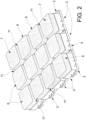
figure 2 is a detailed axonometric view of the system, without the filling material for greater clarity; -
figure 3 is a perspective view of one of the modules of the system according to the invention; -
figure 4 is a perspective view, from a different angle, of the housing of one of the system modules; -
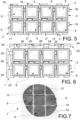
figure 5 is a detailed plan view of the system according to the invention, without the filling material for greater clarity; -
figure 6 is a detailed plan view of another embodiment of the system according to the invention, without the filling material for greater clarity; -
figure 7 is a detailed photograph of the system according to the invention; -
figure 8 is a perspective view of two modules of the system according to the invention, in a further embodiment; -
figure 9 is a perspective view of a series of modules of the system, according to the embodiment offigure 8 , constrained and linked so as to cover a curved or irregular background. - With reference to the attached
figure 1 , thenumber 1 generally indicates a system for the creation of block paving according to the present invention. -
System 1 includes a plurality of modules 2 (figure 3 ), intended to be laid on the surface on which the paving is intended to be created. - The
modules 2, in more detail, are placed next to each other in order to obtain a sort of grid. - According to an aspect of the invention, each of the
modules 2 includes a base 3 (figure 4 ). - The
base 3 of each of themodules 2 includes alower surface 4, for resting on the surface intended for the creation of the paving. - The
base 3 of each of themodules 2 also includes ahousing 5, open at the top. According to another aspect of the invention, each of themodules 2 also includes ablock 6, inserted - in use - inside thehousing 5. - The
block 6, in turn, includes at least oneface 7, intended to constitute (together with thefaces 7 of the other blocks 6) theexternal surface 8 of the paving to be created. - According to a further aspect of the invention, the
base 3 of each of themodules 2 also includes mutual fastening means 9, of a removable type, to thebases 3 of theadjacent modules 2. - According to yet another aspect of the invention, the
system 1 also includes a fillingmaterial 10 of the spaces 11 (see in particularfigure 2 ) included betweenadjacent modules 2. - The
aforementioned filling material 10 is suitable for creatingjoints 12 interposed between thefaces 7 of theblocks 6 of themodules 2 intended to create theexternal surface 8 of the paving. - The 12 joints, for example, can have dimensions of 1 cm wide and 4 cm deep. More in detail, the
base 3 of each of themodules 2 includes abottom 13, andperimeter walls 14, connected to thebottom 13, which define theaforementioned housing 5 for the insertion of therespective block 6. - The
bottom 13 includes, in turn, a central opening 15. - The fastening means 9 of each of the
bases 3 comprisefirst coupling elements 16 andsecond coupling elements 17, associated with theperimeter walls 14 of thebase 3 of each of themodules 2. - In particular, the aforementioned
first coupling elements 16 andsecond coupling elements 17 are configured to mutually couple. - More in detail, the
first coupling elements 16 of abase 3 are configured to couple with thesecond coupling elements 17 of anadjacent base 3. - The
first coupling elements 16 and thesecond coupling elements 17 have complementary geometries. - More specifically, the
first coupling elements 16 include lateral projections associated withrespective perimeter walls 14 of eachbase 3. - The
second coupling elements 17, however, include respectivelateral frame sections 18, also associated withrespective perimeter walls 14 of eachbase 3, which definerespective recesses 19. - These
recesses 19 are shaped, in fact, so as to house thefirst coupling elements 16 to obtain a safe and stable connection betweenadjacent bases 3. - In an embodiment of the invention of particular practical interest, the
base 3 of each of themodules 2 includes fourperimeter walls 14 which form - when theaforementioned base 3 is observed in plan view - a square (or possibly also a rectangle). - Correspondingly, block 6 of each
module 2 also has a parallelepiped shape, with a square or rectangular base. - For example, the dimensions of each
block 6 can be 9 x 9 cm (base) and 4 cm (height). - The
second coupling elements 17 therefore include, in this embodiment, two lateral frame sections 18 - which therefore definerespective recesses 19, or seats - provided along twoadjacent perimeter walls 14 of eachbase 3. - The aforementioned two
lateral frame sections 18 are mutually connected, that is, in other words they constitute, in fact, a single continuous section of frame which surrounds twoadjacent perimeter walls 14 of eachbase 3. - Furthermore, in this embodiment, the fastening means 9 comprise two
first coupling elements 16 provided along the two respective remainingperimeter walls 14, also adjacent to each other, of eachbase 3. - According to a further aspect of the invention, the
first coupling elements 16 and thesecond coupling elements 17 are substantially shaped like a dovetail (and therefore with complementary shapes to each other). - In other words, the
first coupling elements 16 are made up of dovetail-shaped protrusions, while thesecond coupling elements 17 includerecesses 19, also in the shape of a dovetail, of dimensions suitable for housing thefirst coupling elements 16. - This measure therefore makes it possible to obtain a safe and stable mutual connection between the
bases 3 of theadjacent modules 2. - As can be seen, in particular, in
figures 2 and5 , the fastening means 9 between thebases 3 of theadjacent modules 2 are configured - thanks, above all, to the shape and dimensions of the lateral frame sections 18 - in such a way as to guarantee a certain distance between thebases 3 of themodules 2 themselves, and therefore between therespective blocks 6. - The
lateral frame sections 18 of thesecond coupling elements 17, and thefirst coupling elements 16 are, in particular, defined byfurther walls 20 which develop from theperimeter walls 14 of each of thebases 3; thesefurther walls 20 are lower in height than theaforementioned perimeter walls 14. - Furthermore, both the
lateral frame sections 18 of thesecond coupling elements 17 and thefirst coupling elements 16 conform respectivelower portions 21, which are flat and coplanar to the bottom 13 of thebase 3. - According to another aspect of the invention, the bottom 13 and/or the
first coupling elements 16 and/or thesecond coupling elements 17 comprise respective drainage holes 22. - In particular, the drainage holes 22 can be provided in the
lower portions 21 of thefirst coupling elements 16 and in thelateral frame sections 18 of thesecond coupling elements 17. - The drainage holes 22 have the function of facilitating the flow of water from the
various modules 2 ofsystem 1. - In an embodiment of the invention of particular practical interest, the
base 3 of each of themodules 2 is made of injection molded plastic. - Furthermore, in a preferred form of the invention, the
block 6 of each of themodules 2 is made of a material chosen from wood, concrete, terracotta. - For example, each
block 6 could be made of autoclaved pine wood. - According to yet another aspect of the invention, the filling
material 10 of thespaces 11 defined between theblocks 6 of themodules 2 comprises polymeric sand. - This polymeric sand could be of various colors to increase the decorative potential of
system 1. - In an embodiment of the invention, illustrated in detail in
figure 6 , thesystem 1 can include aperimeter curb 23, which surrounds themodules 2 of the system 1 (all or only some of them). - The
perimeter curb 23 can have the function of finishing and/or containing the fillingmaterial 10 ofsystem 1. - The
perimeter curb 23 includes a plurality ofsegments 24; thesegments 24 can be associated with thebases 3 of themodules 2. - The
segments 24 are arranged adjacent to each other, so as to obtain a substantially continuous structure. - Some of the
segments 24, if designed to be installed at the corners of thesystem 1, can have a rounded end, as shown schematically in the aforementionedfigure 6 . - Each of the
segments 24 includes a respectivelateral protrusion 25, or a respective indentation 26 (depending on the positions of thevarious segments 24 with respect to the modules 2); eachprotrusion 25, orindentation 26, has an identical, or substantially identical, shape to that of each of thefirst coupling elements 16, or of thesecond coupling elements 17, of thebases 3. - In this way, each of these
protrusions 25 of thesegments 24 is suitable to engage in arespective recess 19 of asecond coupling element 17 of one of thebases 3 of thesystem 1, so as to obtain a stable constraint of theperimeter curb 23 to thebases 3; or, eachindentation 26 is suitable for housing a respectivefirst coupling element 16 of one of thebases 3. - The
perimeter curb 23 can be made of molded plastic, as are thebases 3 of themodules 2, or of another suitable material (for example, chosen for particular aesthetic reasons). - The
segments 24 can be made with the respective external sides having an angle to the ground less than 90°, for anti-stumbling purposes. - Another embodiment of
system 1 according to the invention is illustrated infigures 8, 9 . - This embodiment differs from the previous embodiment in that the
lower portion 21 of thelateral frame sections 18 also extends to therecesses 19 of thesecond coupling elements 17, so as to obtain, also at each of these, some respective bottom walls. - The
lower portions 21 extended to therecesses 19 also include respective drainage holes 22. - Thanks to this extension of the lower portion 21 - as shown, in particular, in
figure 9 - the system can be easily installed in ground conditions with an irregular or curved surface. - In fact, each
lower portion 21 of eachrecess 19 constitutes a support surface for the correspondingfirst coupling element 16, so that the mutual bond between twoadjacent modules 2 is made more stable, and the risk of accidental detachment is limited. - More in detail, in practice each
lower portion 21 of amodule 2 limits the possible relative rotation of theadjacent module 2, so as to prevent the overall concatenation of themodules 2 from taking on unexpected or irregular shapes, as shown in the aforementionedfigure 9 . - It has thus been seen how the invention achieves the proposed objects.
- The system allows obtaining significant advantages both in terms of the quality of the result (as can be seen in the photograph in
figure 7 ) and in terms of its installation method. - In fact, the system can be easily set up on various types of substrates, for example a rigid substrate such as screed, concrete, asphalt, stone, or a stabilized substrate. The system can be customized in various ways, thanks to the choice of the material of the various blocks 6 (which, naturally, can be identical to each other, but also different) and as regards the choice of the filling
material 10. - The system is considerably more limited in thickness than known installations. Furthermore, thanks to the particular and innovative conformation of the fastening means 9, it can be installed easily and quickly, and equally removed, without ruining the underlying surface.
- The present invention has been described according to preferred embodiments, but equivalent variations can be conceived without departing from the scope of protection offered by the following claims.
Claims (10)
- System (1) for the construction of block pavings, comprising:a plurality of modules (2), intended to be laid on the surface on which the paving is intended to be built, placed next to each other so as to obtain a sort of grid;each of said modules (2) comprising a base (3), comprising a lower surface (4) resting on said surface intended for creating the paving, and a housing (5), open at the top;each of said modules (2) further comprising a block (6), inserted inside said housing (5), comprising, in turn, at least one face (7) intended to constitute the external surface (8) of the paving to be realized;said base (3) of each of said modules (2) comprising fastening means (9), of a removable type, to the bases (3) of the adjacent modules (2);wherein said base (3) of each of said modules (2) includes a bottom (13) and perimeter walls (14) which define said housing (5),wherein said fastening means (9) comprise first coupling elements (16) and second coupling elements (17), associated with said perimeter walls (14) of said base (3) of each of said modules (2), said first coupling elements (16) and said second coupling elements (17) being configured to mutually couple;wherein said first coupling elements (16) and said second coupling elements (17) have complementary geometries, said first coupling elements (16) comprising lateral projections associated with respective perimeter walls (14) of said base (3),said second coupling elements (17) comprising respective lateral frame sections (18), associated with respective perimeter walls (14) of said base (3), which define respective recesses (19), said recesses (19) being shaped so as to house said first coupling elements (16);characterized in that said lateral frame sections (18) of said second coupling elements (17), and said first coupling elements (16), conform respective lower portions (21), flat and coplanar to said bottom (13) of said base (3), and by the fact that said lower portions (21) include respective drainage holes (22).
- System (1) according to claim 1, in which said lower portion (21) of said lateral frame sections (18) also extends to the recesses (19) of said second coupling elements (17), so as to obtain, even at each of said recesses (19), respective bottom walls.
- System (1) according to claim 2, in which said lower portion (21) extended to said recesses (19) includes respective drainage holes (22).
- System (1) according to one of the previous claims, in which said base (3) of each of said modules (2) includes four perimeter walls (14) which conform, when said base (3) is observed in plan, a square or a rectangle, said second coupling elements (17) comprising two lateral frame sections (18), defining the respective recesses (19), provided along two perimeter walls (14) adjacent to each other of said base (3), said fastening means (9) further comprising two first coupling elements (16) provided along the two respective remaining perimeter walls (14), also adjacent to each other, of said base (3).
- System (1) according to one of the previous claims, in which said first coupling elements (16) comprise dovetail-shaped protrusions, while said second coupling elements (17) comprise recesses (19), also dovetail-shaped, of dimensions suitable for housing said first coupling elements (16).
- System (1) according to one of the previous claims, wherein said bottom (13) includes drainage holes (22).
- System (1) according to one of the previous claims, wherein said base (3) of each of said modules (2) is made of injection molded plastic.
- System (1) according to one of the previous claims, in which said block (6) of each of said modules (2) is made of a material chosen from wood, concrete, terracotta.
- System (1) according to one of the previous claims, comprising at least one filling material (10) of the spaces (11) included between adjacent modules (2), suitable for creating joints (12) interposed between said faces (7) of said blocks (6) of said modules (2).
- System (1) according to the previous claim, in which said filling material (10) comprises polymeric sand and/or granulates, possibly of various colours.
Applications Claiming Priority (1)
| Application Number | Priority Date | Filing Date | Title |
|---|---|---|---|
| IT102023000009783A IT202300009783A1 (en) | 2023-05-15 | 2023-05-15 | SYSTEM FOR THE CONSTRUCTION OF BLOCK FLOORING |
Publications (2)
| Publication Number | Publication Date |
|---|---|
| EP4474576A1 true EP4474576A1 (en) | 2024-12-11 |
| EP4474576B1 EP4474576B1 (en) | 2026-04-22 |
Family
ID=88098430
Family Applications (1)
| Application Number | Title | Priority Date | Filing Date |
|---|---|---|---|
| EP24175935.6A Active EP4474576B1 (en) | 2023-05-15 | 2024-05-15 | System for the construction of block pavings |
Country Status (2)
| Country | Link |
|---|---|
| EP (1) | EP4474576B1 (en) |
| IT (1) | IT202300009783A1 (en) |
Citations (3)
| Publication number | Priority date | Publication date | Assignee | Title |
|---|---|---|---|---|
| WO2016107621A1 (en) * | 2014-12-28 | 2016-07-07 | PURUS PLASTICS GmbH | Water-permeable ground grid for pavings |
| GB2605789A (en) * | 2021-04-12 | 2022-10-19 | Alexander Oldham Jake | Apparatus and methods for installing paving |
| US20230016172A1 (en) * | 2021-07-19 | 2023-01-19 | Sievert Jan Benninga | Underlayment Tile and Method of Laying a Modular Surface Covering System |
-
2023
- 2023-05-15 IT IT102023000009783A patent/IT202300009783A1/en unknown
-
2024
- 2024-05-15 EP EP24175935.6A patent/EP4474576B1/en active Active
Patent Citations (3)
| Publication number | Priority date | Publication date | Assignee | Title |
|---|---|---|---|---|
| WO2016107621A1 (en) * | 2014-12-28 | 2016-07-07 | PURUS PLASTICS GmbH | Water-permeable ground grid for pavings |
| GB2605789A (en) * | 2021-04-12 | 2022-10-19 | Alexander Oldham Jake | Apparatus and methods for installing paving |
| US20230016172A1 (en) * | 2021-07-19 | 2023-01-19 | Sievert Jan Benninga | Underlayment Tile and Method of Laying a Modular Surface Covering System |
Also Published As
| Publication number | Publication date |
|---|---|
| IT202300009783A1 (en) | 2024-11-15 |
| EP4474576B1 (en) | 2026-04-22 |
Similar Documents
| Publication | Publication Date | Title |
|---|---|---|
| US7425106B2 (en) | Concrete pavers positioned in a herringbone pattern | |
| US8282310B2 (en) | Paver installation system | |
| JPH04506552A (en) | Square paving material for paved surfaces | |
| CA2461059A1 (en) | Concrete-moulded stone and ready-to-assemble construction made of moulded stones | |
| CN105102725A (en) | Precast leveling segment below a traffic barrier atop an earth retaining wall system | |
| US20100205899A1 (en) | Masonry sub-flooring | |
| EP1306485A1 (en) | Modular removable supports for pavements | |
| EP4474576B1 (en) | System for the construction of block pavings | |
| US7001101B1 (en) | Interlocking paver/tile | |
| US20040120763A1 (en) | Stone for forming a pavement | |
| KR102563746B1 (en) | Prefabricated support plate for sidewalk block and prevention of weeds growth | |
| KR100833688B1 (en) | Road structure and road construction method using sidewalk block to prevent uneven settlement | |
| JPS63236801A (en) | Block tile holding frame | |
| KR100708344B1 (en) | Repair and Pitcher Packaging spacer | |
| KR101274440B1 (en) | boundary stone with strait line and curve line establishment | |
| CN220685680U (en) | Assembled concrete pavement structure | |
| GB2605789A (en) | Apparatus and methods for installing paving | |
| GB2390631A (en) | Apparatus for forming a pavement from a settable material | |
| EP0249376B1 (en) | Paviors | |
| JPH047207Y2 (en) | ||
| KR100924022B1 (en) | How to install the combined sidewalk block for building complex | |
| JPH0330401Y2 (en) | ||
| KR100930359B1 (en) | Green Road Pavement Block Assembly | |
| KR100598771B1 (en) | Road sidewalk block settlement structure | |
| CN211420751U (en) | Concrete brick |
Legal Events
| Date | Code | Title | Description |
|---|---|---|---|
| PUAI | Public reference made under article 153(3) epc to a published international application that has entered the european phase |
Free format text: ORIGINAL CODE: 0009012 |
|
| STAA | Information on the status of an ep patent application or granted ep patent |
Free format text: STATUS: THE APPLICATION HAS BEEN PUBLISHED |
|
| AK | Designated contracting states |
Kind code of ref document: A1 Designated state(s): AL AT BE BG CH CY CZ DE DK EE ES FI FR GB GR HR HU IE IS IT LI LT LU LV MC ME MK MT NL NO PL PT RO RS SE SI SK SM TR |
|
| STAA | Information on the status of an ep patent application or granted ep patent |
Free format text: STATUS: REQUEST FOR EXAMINATION WAS MADE |
|
| 17P | Request for examination filed |
Effective date: 20250610 |
|
| RIC1 | Information provided on ipc code assigned before grant |
Ipc: E01C 5/00 20060101AFI20250925BHEP Ipc: E01C 5/20 20060101ALI20250925BHEP |
|
| GRAP | Despatch of communication of intention to grant a patent |
Free format text: ORIGINAL CODE: EPIDOSNIGR1 |
|
| STAA | Information on the status of an ep patent application or granted ep patent |
Free format text: STATUS: GRANT OF PATENT IS INTENDED |
|
| INTG | Intention to grant announced |
Effective date: 20251117 |
|
| GRAS | Grant fee paid |
Free format text: ORIGINAL CODE: EPIDOSNIGR3 |
|
| GRAA | (expected) grant |
Free format text: ORIGINAL CODE: 0009210 |
|
| STAA | Information on the status of an ep patent application or granted ep patent |
Free format text: STATUS: THE PATENT HAS BEEN GRANTED |
|
| AK | Designated contracting states |
Kind code of ref document: B1 Designated state(s): AL AT BE BG CH CY CZ DE DK EE ES FI FR GB GR HR HU IE IS IT LI LT LU LV MC ME MK MT NL NO PL PT RO RS SE SI SK SM TR |
|
| REG | Reference to a national code |
Ref country code: CH Ref legal event code: F10 Free format text: ST27 STATUS EVENT CODE: U-0-0-F10-F00 (AS PROVIDED BY THE NATIONAL OFFICE) Effective date: 20260422 Ref country code: GB Ref legal event code: FG4D |