EP4474528A2 - Kohlendioxidelektrolysevorrichtung und verfahren zur elektrolyse von kohlendioxid - Google Patents
Kohlendioxidelektrolysevorrichtung und verfahren zur elektrolyse von kohlendioxid Download PDFInfo
- Publication number
- EP4474528A2 EP4474528A2 EP24161710.9A EP24161710A EP4474528A2 EP 4474528 A2 EP4474528 A2 EP 4474528A2 EP 24161710 A EP24161710 A EP 24161710A EP 4474528 A2 EP4474528 A2 EP 4474528A2
- Authority
- EP
- European Patent Office
- Prior art keywords
- switching valve
- opening
- flow path
- carbon dioxide
- electrolytic solution
- Prior art date
- Legal status (The legal status is an assumption and is not a legal conclusion. Google has not performed a legal analysis and makes no representation as to the accuracy of the status listed.)
- Pending
Links
Images





Classifications
-
- C—CHEMISTRY; METALLURGY
- C25—ELECTROLYTIC OR ELECTROPHORETIC PROCESSES; APPARATUS THEREFOR
- C25B—ELECTROLYTIC OR ELECTROPHORETIC PROCESSES FOR THE PRODUCTION OF COMPOUNDS OR NON-METALS; APPARATUS THEREFOR
- C25B1/00—Electrolytic production of inorganic compounds or non-metals
- C25B1/01—Products
- C25B1/02—Hydrogen or oxygen
- C25B1/04—Hydrogen or oxygen by electrolysis of water
-
- C—CHEMISTRY; METALLURGY
- C25—ELECTROLYTIC OR ELECTROPHORETIC PROCESSES; APPARATUS THEREFOR
- C25B—ELECTROLYTIC OR ELECTROPHORETIC PROCESSES FOR THE PRODUCTION OF COMPOUNDS OR NON-METALS; APPARATUS THEREFOR
- C25B1/00—Electrolytic production of inorganic compounds or non-metals
- C25B1/01—Products
- C25B1/23—Carbon monoxide or syngas
-
- C—CHEMISTRY; METALLURGY
- C25—ELECTROLYTIC OR ELECTROPHORETIC PROCESSES; APPARATUS THEREFOR
- C25B—ELECTROLYTIC OR ELECTROPHORETIC PROCESSES FOR THE PRODUCTION OF COMPOUNDS OR NON-METALS; APPARATUS THEREFOR
- C25B15/00—Operating or servicing cells
- C25B15/02—Process control or regulation
-
- C—CHEMISTRY; METALLURGY
- C25—ELECTROLYTIC OR ELECTROPHORETIC PROCESSES; APPARATUS THEREFOR
- C25B—ELECTROLYTIC OR ELECTROPHORETIC PROCESSES FOR THE PRODUCTION OF COMPOUNDS OR NON-METALS; APPARATUS THEREFOR
- C25B15/00—Operating or servicing cells
- C25B15/02—Process control or regulation
- C25B15/023—Measuring, analysing or testing during electrolytic production
- C25B15/025—Measuring, analysing or testing during electrolytic production of electrolyte parameters
- C25B15/027—Temperature
-
- C—CHEMISTRY; METALLURGY
- C25—ELECTROLYTIC OR ELECTROPHORETIC PROCESSES; APPARATUS THEREFOR
- C25B—ELECTROLYTIC OR ELECTROPHORETIC PROCESSES FOR THE PRODUCTION OF COMPOUNDS OR NON-METALS; APPARATUS THEREFOR
- C25B15/00—Operating or servicing cells
- C25B15/02—Process control or regulation
- C25B15/023—Measuring, analysing or testing during electrolytic production
- C25B15/025—Measuring, analysing or testing during electrolytic production of electrolyte parameters
- C25B15/029—Concentration
-
- C—CHEMISTRY; METALLURGY
- C25—ELECTROLYTIC OR ELECTROPHORETIC PROCESSES; APPARATUS THEREFOR
- C25B—ELECTROLYTIC OR ELECTROPHORETIC PROCESSES FOR THE PRODUCTION OF COMPOUNDS OR NON-METALS; APPARATUS THEREFOR
- C25B15/00—Operating or servicing cells
- C25B15/08—Supplying or removing reactants or electrolytes; Regeneration of electrolytes
-
- C—CHEMISTRY; METALLURGY
- C25—ELECTROLYTIC OR ELECTROPHORETIC PROCESSES; APPARATUS THEREFOR
- C25B—ELECTROLYTIC OR ELECTROPHORETIC PROCESSES FOR THE PRODUCTION OF COMPOUNDS OR NON-METALS; APPARATUS THEREFOR
- C25B3/00—Electrolytic production of organic compounds
- C25B3/20—Processes
- C25B3/25—Reduction
- C25B3/26—Reduction of carbon dioxide
-
- C—CHEMISTRY; METALLURGY
- C25—ELECTROLYTIC OR ELECTROPHORETIC PROCESSES; APPARATUS THEREFOR
- C25B—ELECTROLYTIC OR ELECTROPHORETIC PROCESSES FOR THE PRODUCTION OF COMPOUNDS OR NON-METALS; APPARATUS THEREFOR
- C25B9/00—Cells or assemblies of cells; Constructional parts of cells; Assemblies of constructional parts, e.g. electrode-diaphragm assemblies; Process-related cell features
- C25B9/17—Cells comprising dimensionally-stable non-movable electrodes; Assemblies of constructional parts thereof
- C25B9/19—Cells comprising dimensionally-stable non-movable electrodes; Assemblies of constructional parts thereof with diaphragms
- C25B9/23—Cells comprising dimensionally-stable non-movable electrodes; Assemblies of constructional parts thereof with diaphragms comprising ion-exchange membranes in or on which electrode material is embedded
-
- Y—GENERAL TAGGING OF NEW TECHNOLOGICAL DEVELOPMENTS; GENERAL TAGGING OF CROSS-SECTIONAL TECHNOLOGIES SPANNING OVER SEVERAL SECTIONS OF THE IPC; TECHNICAL SUBJECTS COVERED BY FORMER USPC CROSS-REFERENCE ART COLLECTIONS [XRACs] AND DIGESTS
- Y02—TECHNOLOGIES OR APPLICATIONS FOR MITIGATION OR ADAPTATION AGAINST CLIMATE CHANGE
- Y02E—REDUCTION OF GREENHOUSE GAS [GHG] EMISSIONS, RELATED TO ENERGY GENERATION, TRANSMISSION OR DISTRIBUTION
- Y02E60/00—Enabling technologies; Technologies with a potential or indirect contribution to GHG emissions mitigation
- Y02E60/30—Hydrogen technology
- Y02E60/36—Hydrogen production from non-carbon containing sources, e.g. by water electrolysis
Definitions
- Embodiments disclosed herein relate to a carbon dioxide electrolytic device and a method of electrolyzing carbon dioxide.
- CO 2 carbon dioxide
- CO 2 electrolytic device for example, a structure is being studied in which CO 2 gas is brought into contact with a cathode, and an electrolytic solution is brought into contact with an anode.
- Examples of a concrete configuration of an electrolytic device include an electrolysis cell with a cathode, a cathode flow path for CO 2 gas disposed along the cathode, an anode, an anode flow path for an electrolytic solution disposed along the anode, and a separator disposed between these flow paths, for example.
- the electrolytic device having the above configuration When the electrolytic device having the above configuration is used to continuously carry out a reaction to produce, for example, CO from CO 2 , the temperature of the electrolytic solution rises to a high temperature while the electrolytic solution passes through the anode flow path, and an outlet side of the anode flow path of the electrolysis cell may become hot without much heat exchange.
- the high temperature at the outlet side of the anode flow path may cause damage to members such as the separators and electrodes.
- a subject be solved by the aspect of the present invention is to provide a carbon dioxide electrolytic device and a method of electrolyzing carbon dioxide that make it possible to prevent performance degradation, failure, and the like of the electrolysis cell based on damage of members such as separators and electrodes.
- a carbon dioxide electrolytic device and a method of electrolyzing carbon dioxide that make it possible to prevent performance degradation, failure, and the like of the electrolysis cell based on damage of members such as separators and electrodes.
- a carbon dioxide electrolytic device of an embodiment includes: an electrolysis cell that includes a cathode configured to reduce carbon dioxide to produce a carbon compound, an anode configured to oxidize water to produce oxygen, an anode flow path having a first opening provided on one end side and a second opening provided on the other end side and configured to supply an electrolytic solution containing water to the anode, a cathode flow path having a third opening provided on one end side and a fourth opening provided on the other end side and configured to supply carbon dioxide to the cathode, and a separator configured to separate the anode from the cathode; a carbon dioxide supply unit configured to supply the carbon dioxide to the cathode flow path; an electrolytic solution supply unit configured to supply the electrolytic solution to the anode flow path; an external flow path that includes at least one of an electrolytic solution external flow path including a first pipe configured to connect the electrolytic solution supply unit to the first opening of the anode flow path, a second pipe connected to the second opening of the anode flow
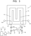
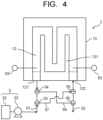
- FIG. 1 to FIG. 4 are views each illustrating an electrolytic device of carbon dioxide (CO 2 ) according to a first embodiment, where FIG. 1 is a sectional view illustrating a first state of the carbon dioxide electrolytic device of the first embodiment, FIG. 2 is a sectional view illustrating a second state of the carbon dioxide electrolytic device of the first embodiment, FIG. 3 is a plan view illustrating a first state of the carbon dioxide electrolytic device on an anode flow path side of the first embodiment, and FIG. 4 is a plan view illustrating a second state of the carbon dioxide electrolytic device on the anode flow path side of the first embodiment.
- An electrolytic device 1 of carbon dioxide (CO 2 ) illustrated in each of FIG. 1 to FIG. 4 includes an electrolysis cell 2, an electrolytic solution supply unit 3 that supplies an electrolytic solution as an anode solution to the electrolysis cell 2, and a carbon dioxide supply unit 4 that supplies carbon dioxide (CO 2 ) gas to the electrolysis cell 2.
- the electrolysis cell 2 includes an anode part 10, a cathode part 20, and a separator 30.
- the anode part 10 includes an anode 11, an anode flow path 12, and an anode flow path plate 13.
- the cathode part 20 includes a cathode 21, a cathode flow path 22, and a cathode flow path plate 23.
- the separator 30 is disposed to separate the anode part 10 from the cathode part 20.
- the electrolysis cell 2 is sandwiched between a pair of current collectors and a pair of support plates, not illustrated, and further tightened with bolts or the like.
- the anode 11 and the cathode 21 are connected to a power supply that supplies current to them, although not illustrated in FIG. 1 to FIG. 4 .
- the power supply is electrically connected to the anode 11 and the cathode 21 through a current introduction member or other members.
- the power supply is not limited to a normal system power supply, battery, or the like, but may be a power source that supplies electric power generated by renewable energy such as a solar cell, wind power generation, or geothermal power generation.
- the anode flow path plate 13 is provided with a first opening 121 and a second opening 122 connected to the anode flow path 12, as illustrated in FIG. 3 and FIG. 4 .
- the anode flow path 12 has a serpentine structure, for example, as illustrated in FIG. 3 and FIG. 4 .
- the first opening 121 and the second opening 122 function as a solution introduction port and a solution discharge port in the anode flow path 12, as described below, and the anode solution is introduced from the electrolytic solution supply unit 3 through the first opening 121 or the second opening 122. Furthermore, the anode solution is discharged through the first opening 121 or the second opening 122 and collected in an electrolytic solution collection unit 31. It may be configured such that the anode solution circulates from the electrolytic solution collection unit 31 to the electrolytic solution supply unit 3.
- the anode 11 includes a base material having a structure capable of making the anode solution and ions move between the separator 30 and the anode flow path 12, for example, a porous structure such as a mesh material, a punching material, a porous body, or a metal fiber sintered body.
- the base material may be composed of a metal such as titanium (Ti), nickel (Ni), or iron (Fe), or a metal material such as an alloy (for example, SUS) containing at least one of these metals, or may be composed of the above-described anode catalyst material.
- a catalyst layer is preferably formed by attaching or stacking the anode catalyst material on a surface of the base material made of the above-described metal material.
- the anode catalyst material may have nanoparticles, a nanostructure, a nanowire, or the like for increasing the oxidation reaction.
- the nanostructure is a structure in which nanoscale irregularities are formed on a surface of the catalyst material.
- the cathode 21 is an electrode (reduction electrode) that causes a reduction reaction of carbon dioxide (CO 2 ), for example, to produce a carbon compound such as carbon monoxide (CO), methane (CH 4 ), ethane (C 2 H 6 ), ethylene (C 2 H 4 ), methanol (CH 3 OH), ethanol (C 2 H 5 OH), or ethylene glycol (C 2 H 6 O 2 ).
- a side reaction in which hydrogen (H 2 ) is produced by a reduction reaction of water (H 2 O) is caused simultaneously with the reduction reaction of carbon dioxide (CO 2 ) in some cases.
- the cathode 21 has a first surface in contact with the separator 30, and a second surface facing the cathode flow path 22.
- Reaction product gases containing CO, H 2 , and other gases are discharged from the cathode flow path 22 through a non-illustrated gas discharge port, and the discharged gases are collected in a product collection unit 41.
- the cathode flow path plate 23 is in electrical contact with a surface of the cathode 21 on a side opposite to the surface that is in contact with the separator 30.
- the cathode 21 has a gas diffusion layer and a cathode catalyst layer, for example. Between the gas diffusion layer and the cathode catalyst layer, a porous layer denser than the gas diffusion layer may be disposed.
- the gas diffusion layer is disposed on the cathode flow path 22 side, and the cathode catalyst layer is disposed on the separator 30 side.
- the cathode catalyst layer may enter the gas diffusion layer.
- the cathode catalyst layer preferably has catalyst nanoparticles, a catalyst nanostructure, or the like.
- the gas diffusion layer is composed of, for example, carbon paper, carbon cloth, or the like, and has been subjected to water-repellent treatment.
- the cathode catalyst layer of the cathode 21 is preferably composed of a catalyst material (cathode catalyst material) capable of reducing CO 2 to produce a carbon compound and capable of decreasing an overvoltage in the above reaction.
- the cathode catalyst material include metals such as gold (Au), silver (Ag), copper (Cu), platinum (Pt), palladium (Pd), nickel (Ni), cobalt (Co), iron (Fe), manganese (Mn), titanium (Ti), cadmium (Cd), zinc (Zn), indium (In), gallium (Ga), lead (Pb), and tin (Sn), metal materials such as alloys and intermetallic compounds containing at least one of the above metals, carbon materials such as carbon (C), graphene, CNT (carbon nanotube), fullerene, and ketjen black, and metal complexes such as a Ru complex and a Re complex.
- the cathode catalyst layer can employ various shapes such as a plate shape, a mesh
- the separator 30 is composed of an ion exchange membrane or the like capable of making the ions and the electrolytic solution move between the anode 11 and the cathode 21, and capable of separating the anode part 10 from the cathode part 20.
- the ion exchange membrane include Neosepta (registered trademark) manufactured by ASTOM Corporation, Selemion (registered trademark) and Aciplex (registered trademark) manufactured by ASAHI GLASS CO., LTD., Fumasep (registered trademark) and Fumapem (registered trademark) manufactured by Fumatech, Nafion (registered trademark) being a fluorine resin made by sulfonating and polymerizing tetrafluoroethylene manufactured by Du Pont, lewabrane (registered trademark) manufactured by LANXESS, IONSEP (registered trademark) manufactured by IONTECH, Mustang (registered trademark) manufactured by PALL, RALEX (registered trademark) manufactured by MEGA, Gore-
- Porous membrane materials include metal oxides, metal hydroxides, metal nitrates, metal sulfates, ceramics, and glass from inorganic materials and polytetrafluoroethylene, polychlorotrifluoroethylene, polyetheretherketone, polyethylene, polyethylene terephthalate, polybutylene terephthalate, cellulose acetate, nitrocellulose, polyphenyl sulfone, polyphenylene sulfide, polysulfone, polyethersulfone, polyacrylonitrile, polyetherimide, polyamideimide, polyvinylidene fluoride, polycarbonate, polyester, polybenzoimidazole, polyarylate, acrylic, nylon, polyolefin, polyurethane, polypropylene, polystyrene from organic materials, and other materials. A combination of each of the materials listed above may also be used.
- a solution containing at least water (H 2 O) is used for the anode solution as the electrolytic solution.
- the solution containing H 2 O used as the anode solution include an aqueous solution containing an arbitrary electrolyte.
- the aqueous solution containing the electrolyte include an aqueous solution containing at least one selected from a hydroxide ion (OH - ), a hydrogen ion (H + ), a potassium ion (K + ), a sodium ion (Na + ), a lithium ion (Li + ), a chloride ion (Cl - ), a bromide ion (Br - ), an iodide ion (I - ), a nitrate ion (NO 3 ), a sulfate ion (SO 4 2- ), a phosphate ion (PO 4 2- ), a borate ion (BO 3 3- ), a carbonate
- a first pipe 51 is connected to the first opening 121 of the anode flow path 12.
- a second pipe 52 is connected to the second opening 122 of the anode flow path 12.
- the first pipe 51 has a first three-way valve 53 as a first switching valve and a second three-way valve 54 as a second switching valve and connects the electrolytic solution supply unit 3 to the first opening 121 through them.
- the second pipe 52 has a third three-way valve 55 as a third switching valve and a fourth three-way valve 56 as a fourth switching valve and connects the second opening 122 to the electrolytic solution collection unit 31 through them.
- the first three-way valve 53 and the third three-way valve 55 are connected by a first bypass pipe 57.
- the second three-way valve 54 and the fourth three-way valve 56 are connected by a second bypass pipe 58.
- the first bypass pipe 57 and the second bypass pipe 58 form a third pipe.
- the first pipe 51, the second pipe 52, and the third pipe (57, 58) form an electrolytic solution external flow path.
- the first three-way valve 53, the second three-way valve 54, the third three-way valve 55, and the fourth three-way valve 56 form an electrolytic solution (flow path) switching mechanism and are further electrically connected to an electrolytic solution switching control unit 61.
- the electrolytic solution switching control unit 61 is configured to switch between a first flow in which the anode solution flows from the first opening 121 toward the second opening 122 through the anode flow path 12 and a second flow in which the anode solution flows from the second opening 122 toward the first opening 121 through the anode flow path 12.
- the switching between the first and second flows is carried out by operations (valve switching operation) of the first three-way valve 53, the second three-way valve 54, the third three-way valve 55, and the fourth three-way valve 56.
- the electrolytic solution supply unit 3 includes an electrolytic solution tank 32 and a pump 33.
- the anode solution as the electrolytic solution may be configured to circulate by the pump 33 from the electrolytic solution collection unit 31 to the electrolytic solution tank 32 of the electrolytic solution supply unit 3.
- a first process of the electrolysis operation of CO 2 is conducted.
- the anode solution is introduced into the anode flow path 12 through the first opening 121 to generate the first flow, while output from the non-illustrated power supply is started to the electrolytic device 1, and a current is supplied by applying a voltage between the anode 11 and the cathode 21.
- a current is supplied by applying a voltage between the anode 11 and the cathode 21.
- the carbon compound as the reduction product of carbon dioxide is not limited to carbon monoxide and may be the above-described organic carbon compounds such as CH 4 , C 2 H 6 , C 2 H 4 , CH 3 OH, C 2 H 5 OH, and C 2 H 6 O 2 .
- H + produced in the anode 11 moves in the anode solution existing in the anode 11 and the separator 30, and reaches the vicinity of the cathode 21.
- the reduction reaction of carbon dioxide (CO 2 ) occurs by electrons (e - ) based on the current supplied from the power supply to the cathode 21 and H + moved to the vicinity of the cathode 21.
- CO 2 supplied from the cathode flow path 22 to the cathode 21 is reduced to produce CO. 2CO 2 + 4H + + 4e - ⁇ 2CO + 2H 2 O ...
- the temperature of the anode solution rises while it passes through the anode flow path 12, and the outlet side of the anode flow path 12 in the electrolysis cell 2 may become hot because heat exchange between the cell and the electrolytic solution does not proceed.
- the high temperature at the outlet side of the anode flow path 12 may cause damage to the separator 30, the anode 11, and the cathode 21.
- thermometer 62 is installed on at least one of the outlet side of the anode flow path 12 and the second pipe 52 to measure the temperature of the anode solution at the outlet side of the anode flow path 12, and according to the measured temperature, the process is changed to a second process using the second flow in which the anode solution flows from the second opening 122 toward the first opening 121 from the first process using the first flow in which the anode solution flows from the first opening 121 toward the second opening 122.
- the change from the first process to the second process is not limited to be carried out by directly measuring the temperature at the outlet side of the anode flow path 12, but for example, by determining in advance a relationship between an elapsed time of a reaction process based on a flow rate of the anode solution and the temperature at the outlet side of the anode flow path 12, and based on the elapsed time of the reaction process when the temperature at the outlet side is expected to reach the temperature in question.
- the supply of the anode solution from the electrolytic solution supply unit 3 is stopped (in some cases, the anode solution supply may not be stopped), then, as illustrated in FIG. 2 and FIG. 4 , the first three-way valve 53 is operated to connect the electrolytic solution supply unit 3 to the first bypass pipe 57 and the third three-way valve 55 is operated to connect the first bypass pipe 57 to the second opening 122 of the anode flow path 12.
- the second three-way valve 54 is operated to connect the first opening 121 of the anode flow path 12 to the second bypass pipe 58
- the fourth three-way valve 56 is operated to connect the second bypass pipe 58 to the electrolytic solution collection unit 31.
- the anode solution flows from the electrolytic solution supply unit 3 to the first bypass pipe 57 through the first three-way valve 53, and then to the anode flow path 12 through the third three-way valve 55 and the second opening 122.
- the anode solution flows from the second opening 122 to the first opening 121 (second flow), opposite to the first process with the first flow.
- thermometer 63 may be installed on at least one of the outlet (first opening 121) side of the anode flow path 12 and the first pipe 51 to measure the temperature of the anode solution at the outlet side of the anode flow path 12, and the process may be changed from the second process to the first process according to the measured temperature.
- the first and second processes may be switched sequentially.
- the first thermometer 62 and the second thermometer 63 form a detection unit and are electrically connected to the electrolytic solution switching control unit 61.
- the detection unit need only be provided with at least one of the first thermometer 62 and the second thermometer 63.
- the above describes a configuration in which the first and second processes are switched based on the detection unit including the thermometer that measures the temperature at the outlet side of the anode flow path 12, but the configuration is not limited thereto.
- the detection unit that detects the state of the anode flow path 12 may be, for example, a pressure sensor, a gas concentration meter, a flow meter, a conductivity meter, a pH sensor, or the like. Since the pressure sensor, the gas concentration meter, and the like indicate the state of the separator 30, the pressure and gas concentration of the anode flow path 12 can be measured to detect the state or the like of the separator 30.
- the state of the separator 30, or the like can be detected by measuring the flow rate of the anode flow path 12.
- the detection unit as described above may be used to switch between the first and second processes. Furthermore, the detection unit as described above may also be disposed in the cathode flow path.
- the cathode part 20 has the cathode flow path 22 and is configured to allow CO 2 gas to flow through from one opening 221 to the other opening 222 of the cathode flow path 22.
- the cathode flow path 22 has the serpentine structure similar to the anode flow path 12 illustrated in FIG. 3 and FIG. 4 , and CO 2 gas flows from the left side of the paper in FIG. 1 to the right side of the paper, for example, the CO 2 gas flows in the same direction as the anode solution in the first process. In contrast, in the second process, the CO 2 gas flows in the opposite direction to the anode solution.
- the CO 2 electrolytic reaction efficiency is almost the same whether the CO 2 gas and the anode solution flow in the same direction or the opposite direction. Therefore, there is no possibility to decrease the electrolytic reaction efficiency of CO 2 by changing the first and second processes.
- the anode flow path 12 and cathode flow path 22 have serpentine flow paths (serpentine structure) illustrated in FIG. 3 and FIG. 4 , for example.
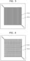
- the flow path structure is not limited to this and may be a parallel flow path illustrated in FIG. 5 , a grid flow path illustrated in FIG. 6 , a dead-end flow path illustrated in FIG. 7 , or other structures, and the structure is not limited.
- the parallel flow path illustrated in FIG. 5 has a structure without folded portions, in which a plurality of parallel flow paths are connected orthogonally to flow paths provided in parallel at both ends.
- the grid flow path illustrated in FIG. 6 has a structure in which a plurality of flow paths are connected in an orthogonal direction to flat flow paths provided on both top and bottom surfaces.
- the dead-end flow path illustrated in FIG. 7 has a structure in which a dead-end flow path is connected from flow paths provided in parallel at both ends to flow paths on an opposite side, respectively.
- the flow path structures of the anode flow path 12 and cathode flow path 22 may be identical or different.
- the anode flow path 12 and cathode flow path 22 preferably have mirror-matched flow path patterns.
- flow path inlets for the anode solution and CO 2 gas may be provided at the same location, and flow path outlets for the anode solution and CO 2 gas may be provided at the same location.
- the flow path inlets for the anode solution and CO 2 gas may be provided at different locations, as illustrated in FIG. 9 .
- the flow path inlets for the anode solution and CO 2 gas may be on a diagonal line or at positions where extensions are orthogonal to each other.
- arrows E22-1, E22-2, and E22-3 each indicate an outlet direction of the CO 2 gas from the cathode flow path 22.
- the CO 2 gas and anode solution may be parallel flows flowing in the same direction or counterflows flowing in opposite directions.
- the structure of the anode flow path 12 and cathode flow path 22, the flow directions of the anode solution and CO 2 gas, and the like are the same in other embodiments described below.
- the CO 2 electrolytic device 1 may include an electrolysis cell stack stacking a plurality of electrolysis cells 2.
- the first and second processes may be changed for the plurality of electrolysis cells 2 in a batch by providing the aforementioned flow path switching mechanism and bypass pipes in an integrated supply system that supplies the anode solution to each of the plurality of electrolysis cells 2 and an integrated discharge system that discharges the anode solution from each of the plurality of electrolysis cells 2. It is also possible to change the first and second processes individually by providing the detection unit and the flow path switching mechanism for each of the plurality of electrolysis cells 2.
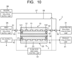
- the carbon dioxide electrolytic device according to a second embodiment is described while referring to FIG. 10 and FIG. 11 .
- differences between the electrolytic device 1 according to the second embodiment and the electrolytic device 1 according to the first embodiment will be explained mainly.
- a structure, composing materials, and the like of the electrolysis cell 2 in the second embodiment are the same as those of the electrolysis cell 2 in the first embodiment, and the second embodiment is basically the same as the first embodiment, except for the parts described the differences below in detail.
- the electrolytic device 1 of the second embodiment includes a first electrolytic solution supply unit 3A and a second electrolytic solution supply unit 3B.
- the first electrolytic solution supply unit 3A is connected to the first opening 121 of the anode flow path 12 through the first pipe 51.
- the first pipe 51 has the first three-way valve 53 as the first switching valve.
- the second pipe 52 is connected to the second opening 122 of the anode flow path 12.
- the second pipe 52 has the second three-way valve 54 as the second switching valve and the third three-way valve 55 as the third switching valve, through which the second opening 122 is connected to the electrolytic solution collection unit 31.
- the second electrolytic solution supply unit 3B is connected to the second three-way valve 54 through the first bypass pipe 57. Furthermore, the third three-way valve 55 is connected to the first three-way valve 53 through the second bypass pipe 58.
- the first three-way valve 53, the second three-way valve 54, and the third three-way valve 55 form the flow path switching mechanism and are further electrically connected to the electrolytic solution switching control unit 61.
- the first bypass pipe 57 and the second bypass pipe 58 form the third pipe.
- the electrolytic solution switching control unit 61 is configured to control switching of the first flow in which the anode solution supplied from the first electrolytic solution supply unit 3A flows from the first opening 121 toward the second opening 122 through the anode flow path 12 and the second flow in which the anode solution supplied from the second electrolytic solution supply unit 3B flows from the second opening 122 toward the first opening 121 through the anode flow path 12.
- the switching between the first and second flows is carried out by the operations of the first and second electrolytic solution supply units 3A and 3B, and the operations of the first three-way valve 53, the second three-way valve 54, and the third three-way valve 55 (valve switching operation). Concrete operations are detailed below.
- the first three-way valve 53 is operated to connect the first electrolytic solution supply unit 3Ato the first opening 121 of the anode flow path 12, and the second and third three-way valves 54 and 55 are operated to connect the second opening 122 of the anode flow path 12 to the electrolytic solution collection unit 31.
- the anode solution supplied from the first electrolytic solution supply unit 3A is then introduced into the anode flow path 12 through the first opening 121, and the anode solution containing reaction products is discharged from the second opening 122 into the electrolytic solution collection unit 31.
- CO 2 gas is introduced into the cathode flow path 22.
- the first three-way valve 53, the second three-way valve 54, the third three-way valve 55, and the fourth three-way valve 56 form an electrolytic solution (flow path) switching mechanism and are further electrically connected to an electrolytic solution switching control unit 61.
- the electrolytic solution switching control unit 61 is configured to switch between a first flow in which the anode solution flows from the first opening 121 toward the second opening 122 through the anode flow path 12 and a second flow in which the anode solution flows from the second opening 122 toward the first opening 121 through the anode flow path 12.
- the switching between the first and second flows is carried out by operations (valve switching operation) of the first three-way valve 53, the second three-way valve 54, the third three-way valve 55, and the fourth three-way valve 56.
- the concrete operation will be described in detail later.
- the electrolytic solution supply unit 3 includes the electrolytic solution tank 32 and the pump 33.
- the first process of the CO 2 electrolysis operation is conducted.
- the anode solution is introduced into the anode flow path 12 through the first opening 121 to generate the first flow, while the output from the non-illustrated power supply is started in the electrolytic device 1 and the current is supplied by applying the voltage between the anode 11 and the cathode 21.
- the current is applied between the anode 11 and the cathode 21
- the oxidation reaction in the vicinity of the anode 11 and the reduction reaction in the vicinity of the cathode 21 occur, as described in the first embodiment.
- carbon monoxide CO
- the carbon compound as the reduction product of carbon dioxide is not limited to carbon monoxide, but can also be the organic carbon compound such as CH 4 , C 2 H 6 , C 2 H 4 , CH 3 OH, C 2 H 5 OH, C 2 H 6 O 2 , or other compounds as mentioned above.
- the concrete reactions are as described in the first embodiment and are omitted here in detail.
- thermometer (not illustrated) is installed on at least one of the outlet side of the anode flow path 12 and the second pipe 52, and according to the temperature at the outlet side of the anode flow path 12, the process is changed from the first process using the first flow in which the anode solution flows from the first opening 121 toward the second opening 122 to the second process using the second flow in which the anode solution flows from the second opening 122 toward the first opening 121.
- the change from the first process to the second process is not limited to be carried out by directly measuring the temperature at the outlet side of the anode flow path 12, but for example, by determining in advance the relationship between the elapsed time of the reaction process based on the flow rate of the anode solution and the temperature at the outlet side of the anode flow path 12, and based on the elapsed time of the reaction process when the temperature at the outlet side is expected to reach the temperature in question.
- the supply of the anode solution from the first electrolytic solution supply unit 3A is stopped, then, as illustrated in FIG. 11 , the first three-way valve 53 is operated to connect the first opening 121 of the anode flow path 12 to the second bypass pipe 58, and the third three-way valve 55 is operated to connect the second bypass pipe 58 to the electrolytic solution collection unit 31.
- the second three-way valve 54 is operated to connect the second opening 122 of the anode flow path 12 to the first bypass pipe 57.
- the second process of the CO 2 electrolysis operation is conducted.
- the anode solution is introduced into the anode flow path 12 through the second opening 122 to generate the second flow, while the current is supplied by applying the voltage between the anode 11 and the cathode 21.
- the CO 2 electrolysis process is conducted in the same manner as in the first process.
- the anode solution is introduced through the second opening 122, that is, the gas discharge port (outlet) in the first process, so that the anode solution with a lower temperature than the anode solution that has passed through the anode flow path 12 in the first process is introduced into the anode flow path 12 through the second opening 122.
- the second process may be changed to the first process depending on the temperature of at least one of the outlet side of the anode flow path 12 and the first pipe 51 as same as the first embodiment.
- the first and second processes may be switched sequentially.
- the detection unit for detecting the temperature needs to include at least one of the first thermometer disposed on the second opening 122 side and the second thermometer disposed on the first opening 121 side.
- the timing of switching between the first and second processes is preferably carried out by detecting the state of the anode flow path 12 by the detection unit including at least one of a thermometer, a pressure sensor, a gas concentration meter, a flow meter, a conductivity meter, and a pH sensor provided in at least one of the openings at both ends of the anode flow path 12 and the pipes connected thereto based on the detection results.
- the detection unit including at least one of a thermometer, a pressure sensor, a gas concentration meter, a flow meter, a conductivity meter, and a pH sensor provided in at least one of the openings at both ends of the anode flow path 12 and the pipes connected thereto based on the detection results.
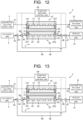
- the carbon dioxide electrolytic device according to a third embodiment is described while referring to FIG. 12 and FIG. 13 .
- differences between the electrolytic device 1 according to the third embodiment and the electrolytic device 1 according to the first embodiment will be explained mainly.
- a structure, composing materials, and the like of the electrolysis cell 2 in the third embodiment are the same as those of the electrolysis cell 2 in the first embodiment, and the third embodiment is basically the same as the first embodiment, except for the parts described the differences below in detail.
- the anode solution flow is configured to be switchable between the first and second flows
- the CO 2 gas flow is configured to be switchable between the third and fourth flows.
- the electrolytic device 1 according to the third embodiment is described in detail below.
- the cathode flow path (CO 2 gas flow path) 22 has one opening (third opening) 221 and the other opening (fourth opening) 222.
- the fourth pipe 42 is connected to the third opening 221 of the CO 2 gas flow path.
- the fifth pipe 43 is connected to the fourth opening 222 of the cathode flow path 22.
- the fourth pipe 42 has a fifth three-way valve 44 as a fifth switching valve and a sixth three-way valve 45 as a sixth switching valve and connects the CO 2 supply unit 4 to the third opening 221 through them.
- the fifth pipe 43 has a seventh three-way valve 46 as a seventh switching valve and an eighth three-way valve 47 as an eighth switching valve and connects the fourth opening 222 to the product collection unit 41 through them.
- the fifth three-way valve 44 and the seventh three-way valve 46 are connected by a third bypass pipe 48.
- the sixth three-way valve 45 and the eighth three-way valve 47 are connected by a fourth bypass pipe 49.
- the third bypass pipe 48 and the fourth bypass pipe 49 form a sixth pipe.
- the fourth pipe 42, the fifth pipe 43, and the sixth pipe (48, 49) form a CO 2 external flow path.
- the fifth three-way valve 44, the sixth three-way valve 45, the seventh three-way valve 46, and the eighth three-way valve 47 form a CO 2 (flow path) switching mechanism and are further electrically connected to a CO 2 (flow path) switching control unit 64.
- the CO 2 switching control unit 64 is configured to switch between a third flow in which the CO 2 gas flows from the third opening 221 toward the fourth opening 222 through the cathode flow path 22 and a fourth flow in which the CO 2 gas flows from the fourth opening 222 toward the third opening 221 through the cathode flow path 22.
- the switching between the third and fourth flows is carried out by operations (valve switching operation) of the fifth three-way valve 44, the sixth three-way valve 45, the seventh three-way valve 46, and the eighth three-way valve 47.
- the fifth and sixth three-way valves 44 and 45 are operated to connect the CO 2 supply unit 4 to the third opening 221 of the cathode flow path 22, and the seventh and eighth three-way valves 46 and 47 are operated to connect the fourth opening 222 of the cathode flow path 22 to the product collection unit 41.
- the CO 2 gas is then introduced into the cathode flow path 22 through the third opening 221, and reaction product gas containing unreacted CO 2 gas is discharged from the fourth opening 222 to the product collection unit 41.
- the anode solution is introduced into the anode flow path 12.
- the anode solution may simply flow from the first opening 121 to the second opening 122 of the anode flow path 12, or the first and second flows may be switched as illustrated in the first embodiment.
- a first process of the electrolysis operation of CO 2 is conducted.
- the CO 2 gas is introduced into the cathode flow path 22 through the third opening 221 to generate the third flow, while output from the non-illustrated power supply is started to the electrolytic device 1, and a current is supplied by applying a voltage between the anode 11 and the cathode 21.
- the current is made to flow between the anode 11 and the cathode 21, the oxidation reaction in the vicinity of the anode 11 and the reduction reaction in the vicinity of the cathode 21 occur.
- the carbon compound as the reduction product of carbon dioxide is not limited to carbon monoxide and may be the above-described organic carbon compounds such as CH 4 , C 2 H 6 , C 2 H 4 , CH 3 OH, C 2 H 5 OH, and C 2 H 6 O 2 .
- the oxidation and reduction reactions at the anode 11 and the cathode 21 were described in detail in the first embodiment, so the descriptions are omitted here.
- a gas concentration meter (first gas concentration meter) 65 is installed on at least one of the outlet sides of the anode flow path 12 and cathode flow path 21 to detect damage to the components of the electrolysis cell 2, and according to the measured values, the process is changed from the first process using the third flow in which the CO 2 gas flows from the third opening 221 toward the fourth opening 222 to the second process using the fourth flow in which the CO 2 gas flows from the fourth opening 222 toward the third opening 221.
- the change from the first process to the second process is not limited to be carried out by directly measuring the gas concentration at the outlet side of the flow path, but for example, based on the elapsed time of the reaction process that is predicted to reach the gas concentration value in question in advance.
- the supply of the CO 2 gas from the CO 2 supply unit 4 is stopped (in some cases, it is not necessary to stop the CO 2 supply), then, as illustrated in FIG. 13 , the fifth three-way valve 44 is operated to connect the CO 2 supply unit 4 to the third bypass pipe 48, and the seventh three-way valve 46 is operated to connect the third bypass pipe 48 to the fourth opening 222 of the cathode flow path 22.
- the sixth three-way valve 45 is operated to connect the third opening 221 of the cathode flow path 22 to the fourth bypass pipe 49
- the eighth three-way valve 47 is operated to connect the fourth bypass pipe 49 to the product collection unit 41.
- the CO 2 gas flows from the CO 2 supply unit 4 to the third bypass pipe 48 through the fifth three-way valve 44 and flows to the cathode flow path 22 through the seventh three-way valve 46 and the fourth opening 222.
- the CO 2 gas flows from the fourth opening 222 toward the third opening 221 (fourth flow), opposite to the first process with the third flow.
- the second process of the CO 2 electrolysis operation is conducted.
- the CO 2 gas is introduced into the cathode flow path 22 through the fourth opening 222 to generate the fourth flow, while the current is supplied by applying the voltage between the anode 11 and the cathode 21.
- the CO 2 electrolysis process is conducted in the same manner as in the first process.
- the CO 2 gas is introduced through the fourth opening 222, that is, the gas discharge port (outlet) in the first process, so that the CO 2 gas with a higher concentration than the CO 2 that has passed through the cathode flow path 22 in the first process is introduced into the cathode flow path 22 through the fourth opening 222.
- a gas concentration meter (second gas concentration meter) 66 may be installed on at least one of the outlet (third opening 221) side of the cathode flow path 22 and the fourth pipe 42, and the process may be changed from the second process to the first process according to the measurement results.
- the first and second processes may be switched sequentially.
- the first and second gas concentration meters constitute a detection unit and are electrically connected to the CO 2 switching control unit 64. The detection unit needs only be equipped with at least one of the first gas concentration meter and the second gas concentration meter.
- the above describes a configuration in which the first and second processes are switched based on a detection unit equipped with a concentration meter that measures the gas concentration at the outlet side of the cathode flow path 22, but the configuration is not limited thereto.
- the detection unit that detects the state of the cathode flow path 22 may be, for example, a pressure sensor, a thermometer, a flow meter, or the like.
- the pressure sensor can indicate the state of damage to the separator 30, while the thermometer and flow meter can detect the state of the cathode and anode.
- the above detection unit may be used to switch between the first and second processes.
- the detection unit as described above may also be disposed in the anode flow path 12 to switch to the cathode flow path 22 side.
- the first and second processes may be changed for the plurality of electrolysis cells 2 in a batch by providing the aforementioned flow path switching mechanism and bypass pipes in an integrated supply system that supplies the CO 2 gas to each of the plurality of electrolysis cells 2 and an integrated discharge system that discharges the product from each of the plurality of electrolysis cells 2. It is also possible to change the first and second processes individually by providing the detection unit and the flow path switching mechanism for each of the plurality of electrolysis cells 2.
- the CO 2 electrolytic device 1 may include both the cathode-side flow path switching mechanism and the anode-side flow path switching mechanism. In this case, it is preferable because switching can be carried out according to the state (switching factor) of the electrolysis cell 2.
- the first process on the cathode side and the first process on the anode side may be parallel flow, where both the electrolytic solution and CO 2 gas flow from the same direction, or they may be counter flow, where they flow in opposite directions.
- the drawing illustrates a general serpentine-type flow path, the flow path structure is not limited to this pattern but may be other patterns as described above. For example, the parallel flow path illustrated in FIG. 5 , the grid flow path illustrated in FIG. 6 , the dead-end flow path illustrated in FIG.
- the anode solution and CO 2 gas flow path inlets may be provided at the same location and the anode solution and CO 2 gas flow path outlets at the same location, or the anode solution and CO 2 gas flow path inlets may be provided at different locations.
- the flow path inlets may be on a diagonal line or at locations where extension lines are orthogonal to each other.
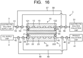
- the carbon dioxide electrolytic device according to a fourth embodiment is described while referring to FIG. 14 and FIG. 15 .
- differences between the electrolytic device 1 according to the fourth embodiment and the electrolytic device 1 according to the second embodiment will be explained mainly.
- a structure, composing materials, and the like of the electrolysis cell 2 in the fourth embodiment are the same as those of the electrolysis cell 2 in the first embodiment, and the fourth embodiment is basically the same as the first embodiment, except for the parts described the differences below in detail.
- the electrolytic device 1 of the fourth embodiment includes a first CO 2 supply unit 4A and a second CO 2 supply unit 4B.
- the first CO 2 supply unit 4A is connected to the third opening 221 of the cathode flow path 22 through the fourth pipe 42.
- the fourth pipe 42 has the fifth three-way valve 44 as the fifth switching valve.
- the fifth pipe 43 is connected to the fourth opening 222 of the cathode flow path 22.
- the fifth pipe 43 has the sixth three-way valve 45 as the sixth switching valve and the seventh three-way valve 46 as the seventh switching valve and connects the fourth opening 222 to the product collection unit 41 through them.
- the second CO 2 supply unit 4B is connected to the sixth three-way valve 45 through the first bypass pipe 48. Furthermore, the seventh three-way valve 46 is connected to the fifth three-way valve 44 through the second bypass pipe 49.
- the fifth three-way valve 44, the sixth three-way valve 45, and the seventh three-way valve 46 constitute the CO 2 (flow path) switching mechanism and are further electrically connected to the CO 2 switching control unit 64.
- the first bypass pipe 48 and the second bypass pipe 49 constitute the third pipe.
- the CO 2 switching control unit 64 is configured to switch between the third flow in which the CO 2 gas supplied from the first CO 2 supply unit 4A flows from the third opening 221 toward the fourth opening 222 through the cathode flow path 22 and the fourth flow in which the CO 2 gas supplied from the second CO 2 supply unit 4B flows from the fourth opening 222 toward the third opening 221 through the cathode flow path 22.
- the switching between the third and fourth flows is carried out by operations of the first CO 2 supply unit 4A and the second CO 2 supply unit 4B and operations (valve switching operation) of the fifth three-way valve 44, the sixth three-way valve 45, and the seventh three-way valve 46.
- the fifth three-way valve 44 is operated to connect the first CO 2 supply unit 4A to the third opening 221 of the cathode flow path 22, and the sixth and seventh three-way valves 45 and 46 are operated to connect the fourth opening 222 of the cathode flow path 22 to the product collection unit 41.
- the CO 2 gas supplied from the first CO 2 supply unit 4A is then introduced into the cathode flow path 22 through the third opening 221, and reaction product gas (CO gas, or other gases) containing unreacted CO 2 gas is discharged from the fourth opening 222 to the product collection unit 41.
- reaction product gas CO gas, or other gases
- the fifth three-way valve 44, the sixth three-way valve 45, and the seventh three-way valve 46 constitute the CO 2 (flow path) switching mechanism and are further electrically connected to the CO 2 switching control unit 64.
- the CO 2 switching control unit 64 is configured to switch between the third flow in which the CO 2 gas flows from the third opening 221 toward the fourth opening 222 through the cathode flow path 22 and the fourth flow in which the CO 2 gas flows from the fourth opening 222 toward the third opening 221 through the cathode flow path 22.
- the switching between the third and fourth flows is carried out by operations (valve switching operation) of the fifth three-way valve 44, the sixth three-way valve 45, and the seventh three-way valve 46.
- a first process of the electrolysis operation of CO 2 is conducted.
- the CO 2 gas is introduced into the cathode flow path 22 through the third opening 221 to generate the third flow, while output from the non-illustrated power supply is started to the electrolytic device 1, and a current is supplied by applying a voltage between the anode 11 and the cathode 21.
- the current is made to flow between the anode 11 and the cathode 21, the oxidation reaction in the vicinity of the anode 11 and the reduction reaction in the vicinity of the cathode 21 occur, as described in the first embodiment.
- carbon monoxide CO
- the carbon compound as the reduction product of carbon dioxide is not limited to carbon monoxide and may be the above-described organic carbon compounds such as CH 4 , C 2 H 6 , C 2 H 4 , CH 3 OH, C 2 H 5 OH, and C 2 H 6 O 2 . Concrete reactions are as described in the first embodiment, so the descriptions are omitted here.
- a gas concentration meter (first gas concentration meter) 65 is installed on at least one of the outlet sides of the anode flow path 12 and cathode flow path 21 to detect damage to the components of the electrolysis cell 2, and according to the measured values, the process is changed from the first process using the third flow in which the CO 2 gas flows from the third opening 221 toward the fourth opening 222 to the second process using the fourth flow in which the CO 2 gas flows from the fourth opening 222 toward the third opening 221.
- the change from the first process to the second process is not limited to be carried out by directly measuring the gas concentration at the outlet side of the flow path, but for example, based on the elapsed time of the reaction process that is predicted to reach the gas concentration value in question in advance.
- the supply of the CO 2 gas from the first CO 2 supply unit 4A is stopped, then, as illustrated in FIG. 15 , the fifth three-way valve 44 is operated to connect the third opening 221 of the cathode flow path 22 to the second bypass pipe 49, and the seventh three-way valve 46 is operated to connect the second bypass pipe 49 to the product collection unit 41.
- the sixth three-way valve 45 is operated to connect the fourth opening 222 of the cathode flow path 22 to the first bypass pipe 48.
- the second process of the CO 2 electrolysis operation is conducted.
- the CO 2 gas is introduced into the cathode flow path 22 through the fourth opening 222 to generate the fourth flow, while the current is supplied by applying the voltage between the anode 11 and the cathode 21.
- the CO 2 electrolysis process is conducted in the same manner as in the first process.
- the CO 2 gas is introduced through the fourth opening 222, that is, the gas discharge port (outlet) in the first process, so that the CO 2 gas with a higher CO 2 concentration than the CO 2 that has passed through the cathode flow path 22 in the first process is introduced into the cathode flow path 22 through the fourth opening 222.
- the second process can be changed to the first process depending on the gas concentration and pH of at least one of the outlet side of the cathode flow channel 22 and the first pipe 42.
- the first and second processes may be switched sequentially.
- the detection unit for detecting the gas concentration can be at least one of the first gas concentration meter 65 disposed on the fourth opening 222 side and the second gas concentration meter 66 disposed on the third opening 221 side, as in the third embodiment.
- the timing for switching between the first and second processes is preferably based on the detection of the state of the cathode flow path 22 by a detection unit equipped with at least one of a gas concentration meter, pH meter, pressure sensor, thermometer, and flow meter installed in the openings at both ends of the cathode flow path 22 and at least one of the pipes connected thereto, and based on the detection results
- the carbon dioxide electrolytic device includes the electrolytic solution (flow path) switching mechanism having the first three-way valve 53, the second three-way valve 54, the third three-way valve 55, the fourth three-way valve 56, and the bypass pipes 57 and 58 as in the first embodiment.
- the cathode-side external flow path includes the CO 2 (flow path) switching mechanism having the fifth three-way valve 44, the sixth three-way valve 45, the seventh three-way valve 46, the eighth three-way valve 47, and the bypass pipes 48 and 49, as in the third embodiment.
- the concrete configurations of the external flow path and switching mechanism are as described in detail in the first and third embodiments.
- the first and second flows of the anode solution electrolytic solution
- the third and fourth flows of the CO 2 gas can be switched based on the measurement results, and the like of gas concentration meters and pH meters installed in the cathode flow path 22 and the pipes 42 and 43 connected thereto, as described in the third embodiment.
- the switching of the first and second flows in the anode solution and the third and fourth flows in the CO 2 gas can be carried out simultaneously.
- the electrolytic device 1 of the fifth embodiment is not limited to the combination of the first and third embodiments but may be a combination of the first and fourth embodiments, a combination of the second and third embodiments, a combination of the second and fourth embodiments, or other combinations.
- various patterns of the anode and cathode flow paths can be applied, such as mirror-matched flow path patterns, combinations of different flow path patterns, or other patterns, as described above, and are not limited thereto.
Landscapes
- Chemical & Material Sciences (AREA)
- Engineering & Computer Science (AREA)
- Organic Chemistry (AREA)
- Chemical Kinetics & Catalysis (AREA)
- Electrochemistry (AREA)
- Materials Engineering (AREA)
- Metallurgy (AREA)
- Automation & Control Theory (AREA)
- Analytical Chemistry (AREA)
- Inorganic Chemistry (AREA)
- Electrolytic Production Of Non-Metals, Compounds, Apparatuses Therefor (AREA)
Applications Claiming Priority (2)
| Application Number | Priority Date | Filing Date | Title |
|---|---|---|---|
| JP2023044168 | 2023-03-20 | ||
| JP2024007713A JP2024134518A (ja) | 2023-03-20 | 2024-01-23 | 二酸化炭素電解装置及び二酸化炭素電解方法 |
Publications (2)
| Publication Number | Publication Date |
|---|---|
| EP4474528A2 true EP4474528A2 (de) | 2024-12-11 |
| EP4474528A3 EP4474528A3 (de) | 2025-04-23 |
Family
ID=90362179
Family Applications (1)
| Application Number | Title | Priority Date | Filing Date |
|---|---|---|---|
| EP24161710.9A Pending EP4474528A3 (de) | 2023-03-20 | 2024-03-06 | Kohlendioxidelektrolysevorrichtung und verfahren zur elektrolyse von kohlendioxid |
Country Status (3)
| Country | Link |
|---|---|
| US (1) | US20240318326A1 (de) |
| EP (1) | EP4474528A3 (de) |
| AU (1) | AU2024201443B2 (de) |
Family Cites Families (2)
| Publication number | Priority date | Publication date | Assignee | Title |
|---|---|---|---|---|
| JP7242601B2 (ja) * | 2020-03-23 | 2023-03-20 | 株式会社東芝 | 二酸化炭素電解装置 |
| JP7520754B2 (ja) * | 2021-03-15 | 2024-07-23 | 株式会社東芝 | 二酸化炭素電解装置及び二酸化炭素電解方法 |
-
2024
- 2024-03-05 AU AU2024201443A patent/AU2024201443B2/en active Active
- 2024-03-06 EP EP24161710.9A patent/EP4474528A3/de active Pending
- 2024-03-06 US US18/596,711 patent/US20240318326A1/en active Pending
Also Published As
| Publication number | Publication date |
|---|---|
| AU2024201443A1 (en) | 2024-10-10 |
| US20240318326A1 (en) | 2024-09-26 |
| EP4474528A3 (de) | 2025-04-23 |
| AU2024201443B2 (en) | 2026-01-22 |
Similar Documents
| Publication | Publication Date | Title |
|---|---|---|
| US11230772B2 (en) | Carbon dioxide electrolytic device and method of electrolyzing carbon dioxide | |
| US11286573B2 (en) | Carbon dioxide electrolytic device and method of electrolyzing carbon dioxide | |
| US10961632B2 (en) | Carbon dioxide electrolytic device and method of electrolyzing carbon dioxide | |
| US11293109B2 (en) | Carbon dioxide electrolytic device | |
| US20210079541A1 (en) | Carbon dioxide electrolytic device and method of electrolyzing carbon dioxide | |
| US10865490B2 (en) | Carbon dioxide electrolytic device | |
| JP6672211B2 (ja) | 二酸化炭素電解装置および二酸化炭素電解方法 | |
| US10626509B2 (en) | Electrolysis cell and electrolytic device for carbon dioxide | |
| US12241170B2 (en) | Carbon dioxide electrolytic device | |
| CN108570690A (zh) | 二氧化碳电解装置 | |
| US11098409B2 (en) | Electrolytic cell and electrolytic device for carbon dioxide | |
| US12031219B2 (en) | Carbon dioxide electrolytic device and method of electrolyzing carbon dioxide | |
| US20240318326A1 (en) | Carbon dioxide electrolytic device and method of electrolyzing carbon dioxide | |
| CN118668221A (zh) | 二氧化碳电解装置和二氧化碳电解方法 | |
| JP2024134518A (ja) | 二酸化炭素電解装置及び二酸化炭素電解方法 | |
| US20250092550A1 (en) | Electrochemical reaction device and method of operating electrochemical reaction device | |
| US20260081195A1 (en) | Membrane electrode assembly, electrochemical cell, stack, and electrolytic system | |
| EP4435145A2 (de) | Elektrolysevorrichtung | |
| CN121700426A (zh) | 电化学反应装置的运转方法和电化学反应装置 |
Legal Events
| Date | Code | Title | Description |
|---|---|---|---|
| PUAI | Public reference made under article 153(3) epc to a published international application that has entered the european phase |
Free format text: ORIGINAL CODE: 0009012 |
|
| STAA | Information on the status of an ep patent application or granted ep patent |
Free format text: STATUS: REQUEST FOR EXAMINATION WAS MADE |
|
| 17P | Request for examination filed |
Effective date: 20240306 |
|
| AK | Designated contracting states |
Kind code of ref document: A2 Designated state(s): AL AT BE BG CH CY CZ DE DK EE ES FI FR GB GR HR HU IE IS IT LI LT LU LV MC ME MK MT NL NO PL PT RO RS SE SI SK SM TR |
|
| PUAL | Search report despatched |
Free format text: ORIGINAL CODE: 0009013 |
|
| AK | Designated contracting states |
Kind code of ref document: A3 Designated state(s): AL AT BE BG CH CY CZ DE DK EE ES FI FR GB GR HR HU IE IS IT LI LT LU LV MC ME MK MT NL NO PL PT RO RS SE SI SK SM TR |
|
| RIC1 | Information provided on ipc code assigned before grant |
Ipc: C25B 15/08 20060101ALI20250314BHEP Ipc: C25B 15/029 20210101ALI20250314BHEP Ipc: C25B 15/027 20210101ALI20250314BHEP Ipc: C25B 15/02 20210101ALI20250314BHEP Ipc: C25B 9/23 20210101ALI20250314BHEP Ipc: C25B 3/26 20210101ALI20250314BHEP Ipc: C25B 1/23 20210101AFI20250314BHEP |