EP4474512A1 - High-strength steel sheet and manufacturing method therefor - Google Patents
High-strength steel sheet and manufacturing method therefor Download PDFInfo
- Publication number
- EP4474512A1 EP4474512A1 EP23774242.4A EP23774242A EP4474512A1 EP 4474512 A1 EP4474512 A1 EP 4474512A1 EP 23774242 A EP23774242 A EP 23774242A EP 4474512 A1 EP4474512 A1 EP 4474512A1
- Authority
- EP
- European Patent Office
- Prior art keywords
- less
- inv
- steel sheet
- temperature
- content
- Prior art date
- Legal status (The legal status is an assumption and is not a legal conclusion. Google has not performed a legal analysis and makes no representation as to the accuracy of the status listed.)
- Pending
Links
Images

Classifications
-
- C—CHEMISTRY; METALLURGY
- C22—METALLURGY; FERROUS OR NON-FERROUS ALLOYS; TREATMENT OF ALLOYS OR NON-FERROUS METALS
- C22C—ALLOYS
- C22C38/00—Ferrous alloys, e.g. steel alloys
- C22C38/04—Ferrous alloys, e.g. steel alloys containing manganese
-
- C—CHEMISTRY; METALLURGY
- C21—METALLURGY OF IRON
- C21D—MODIFYING THE PHYSICAL STRUCTURE OF FERROUS METALS; GENERAL DEVICES FOR HEAT TREATMENT OF FERROUS OR NON-FERROUS METALS OR ALLOYS; MAKING METAL MALLEABLE, e.g. BY DECARBURISATION OR TEMPERING
- C21D1/00—General methods or devices for heat treatment, e.g. annealing, hardening, quenching or tempering
- C21D1/18—Hardening; Quenching with or without subsequent tempering
-
- C—CHEMISTRY; METALLURGY
- C21—METALLURGY OF IRON
- C21D—MODIFYING THE PHYSICAL STRUCTURE OF FERROUS METALS; GENERAL DEVICES FOR HEAT TREATMENT OF FERROUS OR NON-FERROUS METALS OR ALLOYS; MAKING METAL MALLEABLE, e.g. BY DECARBURISATION OR TEMPERING
- C21D6/00—Heat treatment of ferrous alloys
- C21D6/005—Heat treatment of ferrous alloys containing Mn
-
- C—CHEMISTRY; METALLURGY
- C21—METALLURGY OF IRON
- C21D—MODIFYING THE PHYSICAL STRUCTURE OF FERROUS METALS; GENERAL DEVICES FOR HEAT TREATMENT OF FERROUS OR NON-FERROUS METALS OR ALLOYS; MAKING METAL MALLEABLE, e.g. BY DECARBURISATION OR TEMPERING
- C21D8/00—Modifying the physical properties of ferrous metals or ferrous alloys by deformation combined with, or followed by, heat treatment
- C21D8/02—Modifying the physical properties of ferrous metals or ferrous alloys by deformation combined with, or followed by, heat treatment during manufacturing of plates or strips
-
- C—CHEMISTRY; METALLURGY
- C21—METALLURGY OF IRON
- C21D—MODIFYING THE PHYSICAL STRUCTURE OF FERROUS METALS; GENERAL DEVICES FOR HEAT TREATMENT OF FERROUS OR NON-FERROUS METALS OR ALLOYS; MAKING METAL MALLEABLE, e.g. BY DECARBURISATION OR TEMPERING
- C21D8/00—Modifying the physical properties of ferrous metals or ferrous alloys by deformation combined with, or followed by, heat treatment
- C21D8/02—Modifying the physical properties of ferrous metals or ferrous alloys by deformation combined with, or followed by, heat treatment during manufacturing of plates or strips
- C21D8/0221—Modifying the physical properties of ferrous metals or ferrous alloys by deformation combined with, or followed by, heat treatment during manufacturing of plates or strips characterised by the working steps
- C21D8/0226—Hot rolling
-
- C—CHEMISTRY; METALLURGY
- C21—METALLURGY OF IRON
- C21D—MODIFYING THE PHYSICAL STRUCTURE OF FERROUS METALS; GENERAL DEVICES FOR HEAT TREATMENT OF FERROUS OR NON-FERROUS METALS OR ALLOYS; MAKING METAL MALLEABLE, e.g. BY DECARBURISATION OR TEMPERING
- C21D8/00—Modifying the physical properties of ferrous metals or ferrous alloys by deformation combined with, or followed by, heat treatment
- C21D8/02—Modifying the physical properties of ferrous metals or ferrous alloys by deformation combined with, or followed by, heat treatment during manufacturing of plates or strips
- C21D8/0221—Modifying the physical properties of ferrous metals or ferrous alloys by deformation combined with, or followed by, heat treatment during manufacturing of plates or strips characterised by the working steps
- C21D8/0236—Cold rolling
-
- C—CHEMISTRY; METALLURGY
- C21—METALLURGY OF IRON
- C21D—MODIFYING THE PHYSICAL STRUCTURE OF FERROUS METALS; GENERAL DEVICES FOR HEAT TREATMENT OF FERROUS OR NON-FERROUS METALS OR ALLOYS; MAKING METAL MALLEABLE, e.g. BY DECARBURISATION OR TEMPERING
- C21D8/00—Modifying the physical properties of ferrous metals or ferrous alloys by deformation combined with, or followed by, heat treatment
- C21D8/02—Modifying the physical properties of ferrous metals or ferrous alloys by deformation combined with, or followed by, heat treatment during manufacturing of plates or strips
- C21D8/0247—Modifying the physical properties of ferrous metals or ferrous alloys by deformation combined with, or followed by, heat treatment during manufacturing of plates or strips characterised by the heat treatment
- C21D8/0263—Modifying the physical properties of ferrous metals or ferrous alloys by deformation combined with, or followed by, heat treatment during manufacturing of plates or strips characterised by the heat treatment following hot rolling
-
- C—CHEMISTRY; METALLURGY
- C21—METALLURGY OF IRON
- C21D—MODIFYING THE PHYSICAL STRUCTURE OF FERROUS METALS; GENERAL DEVICES FOR HEAT TREATMENT OF FERROUS OR NON-FERROUS METALS OR ALLOYS; MAKING METAL MALLEABLE, e.g. BY DECARBURISATION OR TEMPERING
- C21D8/00—Modifying the physical properties of ferrous metals or ferrous alloys by deformation combined with, or followed by, heat treatment
- C21D8/02—Modifying the physical properties of ferrous metals or ferrous alloys by deformation combined with, or followed by, heat treatment during manufacturing of plates or strips
- C21D8/0247—Modifying the physical properties of ferrous metals or ferrous alloys by deformation combined with, or followed by, heat treatment during manufacturing of plates or strips characterised by the heat treatment
- C21D8/0273—Final recrystallisation annealing
-
- C—CHEMISTRY; METALLURGY
- C21—METALLURGY OF IRON
- C21D—MODIFYING THE PHYSICAL STRUCTURE OF FERROUS METALS; GENERAL DEVICES FOR HEAT TREATMENT OF FERROUS OR NON-FERROUS METALS OR ALLOYS; MAKING METAL MALLEABLE, e.g. BY DECARBURISATION OR TEMPERING
- C21D8/00—Modifying the physical properties of ferrous metals or ferrous alloys by deformation combined with, or followed by, heat treatment
- C21D8/02—Modifying the physical properties of ferrous metals or ferrous alloys by deformation combined with, or followed by, heat treatment during manufacturing of plates or strips
- C21D8/0278—Modifying the physical properties of ferrous metals or ferrous alloys by deformation combined with, or followed by, heat treatment during manufacturing of plates or strips involving a particular surface treatment
-
- C—CHEMISTRY; METALLURGY
- C21—METALLURGY OF IRON
- C21D—MODIFYING THE PHYSICAL STRUCTURE OF FERROUS METALS; GENERAL DEVICES FOR HEAT TREATMENT OF FERROUS OR NON-FERROUS METALS OR ALLOYS; MAKING METAL MALLEABLE, e.g. BY DECARBURISATION OR TEMPERING
- C21D9/00—Heat treatment, e.g. annealing, hardening, quenching or tempering, adapted for particular articles; Furnaces therefor
- C21D9/46—Heat treatment, e.g. annealing, hardening, quenching or tempering, adapted for particular articles; Furnaces therefor for sheet metals
-
- C—CHEMISTRY; METALLURGY
- C22—METALLURGY; FERROUS OR NON-FERROUS ALLOYS; TREATMENT OF ALLOYS OR NON-FERROUS METALS
- C22C—ALLOYS
- C22C38/00—Ferrous alloys, e.g. steel alloys
- C22C38/001—Ferrous alloys, e.g. steel alloys containing N
-
- C—CHEMISTRY; METALLURGY
- C22—METALLURGY; FERROUS OR NON-FERROUS ALLOYS; TREATMENT OF ALLOYS OR NON-FERROUS METALS
- C22C—ALLOYS
- C22C38/00—Ferrous alloys, e.g. steel alloys
- C22C38/002—Ferrous alloys, e.g. steel alloys containing In, Mg, or other elements not provided for in one single group C22C38/001 - C22C38/60
-
- C—CHEMISTRY; METALLURGY
- C22—METALLURGY; FERROUS OR NON-FERROUS ALLOYS; TREATMENT OF ALLOYS OR NON-FERROUS METALS
- C22C—ALLOYS
- C22C38/00—Ferrous alloys, e.g. steel alloys
- C22C38/005—Ferrous alloys, e.g. steel alloys containing rare earths, i.e. Sc, Y, Lanthanides
-
- C—CHEMISTRY; METALLURGY
- C22—METALLURGY; FERROUS OR NON-FERROUS ALLOYS; TREATMENT OF ALLOYS OR NON-FERROUS METALS
- C22C—ALLOYS
- C22C38/00—Ferrous alloys, e.g. steel alloys
- C22C38/008—Ferrous alloys, e.g. steel alloys containing tin
-
- C—CHEMISTRY; METALLURGY
- C22—METALLURGY; FERROUS OR NON-FERROUS ALLOYS; TREATMENT OF ALLOYS OR NON-FERROUS METALS
- C22C—ALLOYS
- C22C38/00—Ferrous alloys, e.g. steel alloys
- C22C38/02—Ferrous alloys, e.g. steel alloys containing silicon
-
- C—CHEMISTRY; METALLURGY
- C22—METALLURGY; FERROUS OR NON-FERROUS ALLOYS; TREATMENT OF ALLOYS OR NON-FERROUS METALS
- C22C—ALLOYS
- C22C38/00—Ferrous alloys, e.g. steel alloys
- C22C38/06—Ferrous alloys, e.g. steel alloys containing aluminium
-
- C—CHEMISTRY; METALLURGY
- C22—METALLURGY; FERROUS OR NON-FERROUS ALLOYS; TREATMENT OF ALLOYS OR NON-FERROUS METALS
- C22C—ALLOYS
- C22C38/00—Ferrous alloys, e.g. steel alloys
- C22C38/08—Ferrous alloys, e.g. steel alloys containing nickel
-
- C—CHEMISTRY; METALLURGY
- C22—METALLURGY; FERROUS OR NON-FERROUS ALLOYS; TREATMENT OF ALLOYS OR NON-FERROUS METALS
- C22C—ALLOYS
- C22C38/00—Ferrous alloys, e.g. steel alloys
- C22C38/10—Ferrous alloys, e.g. steel alloys containing cobalt
-
- C—CHEMISTRY; METALLURGY
- C22—METALLURGY; FERROUS OR NON-FERROUS ALLOYS; TREATMENT OF ALLOYS OR NON-FERROUS METALS
- C22C—ALLOYS
- C22C38/00—Ferrous alloys, e.g. steel alloys
- C22C38/12—Ferrous alloys, e.g. steel alloys containing tungsten, tantalum, molybdenum, vanadium, or niobium
-
- C—CHEMISTRY; METALLURGY
- C22—METALLURGY; FERROUS OR NON-FERROUS ALLOYS; TREATMENT OF ALLOYS OR NON-FERROUS METALS
- C22C—ALLOYS
- C22C38/00—Ferrous alloys, e.g. steel alloys
- C22C38/14—Ferrous alloys, e.g. steel alloys containing titanium or zirconium
-
- C—CHEMISTRY; METALLURGY
- C22—METALLURGY; FERROUS OR NON-FERROUS ALLOYS; TREATMENT OF ALLOYS OR NON-FERROUS METALS
- C22C—ALLOYS
- C22C38/00—Ferrous alloys, e.g. steel alloys
- C22C38/16—Ferrous alloys, e.g. steel alloys containing copper
-
- C—CHEMISTRY; METALLURGY
- C22—METALLURGY; FERROUS OR NON-FERROUS ALLOYS; TREATMENT OF ALLOYS OR NON-FERROUS METALS
- C22C—ALLOYS
- C22C38/00—Ferrous alloys, e.g. steel alloys
- C22C38/18—Ferrous alloys, e.g. steel alloys containing chromium
- C22C38/32—Ferrous alloys, e.g. steel alloys containing chromium with boron
-
- C—CHEMISTRY; METALLURGY
- C22—METALLURGY; FERROUS OR NON-FERROUS ALLOYS; TREATMENT OF ALLOYS OR NON-FERROUS METALS
- C22C—ALLOYS
- C22C38/00—Ferrous alloys, e.g. steel alloys
- C22C38/18—Ferrous alloys, e.g. steel alloys containing chromium
- C22C38/34—Ferrous alloys, e.g. steel alloys containing chromium with more than 1.5% by weight of silicon
-
- C—CHEMISTRY; METALLURGY
- C22—METALLURGY; FERROUS OR NON-FERROUS ALLOYS; TREATMENT OF ALLOYS OR NON-FERROUS METALS
- C22C—ALLOYS
- C22C38/00—Ferrous alloys, e.g. steel alloys
- C22C38/18—Ferrous alloys, e.g. steel alloys containing chromium
- C22C38/38—Ferrous alloys, e.g. steel alloys containing chromium with more than 1.5% by weight of manganese
-
- C—CHEMISTRY; METALLURGY
- C22—METALLURGY; FERROUS OR NON-FERROUS ALLOYS; TREATMENT OF ALLOYS OR NON-FERROUS METALS
- C22C—ALLOYS
- C22C38/00—Ferrous alloys, e.g. steel alloys
- C22C38/60—Ferrous alloys, e.g. steel alloys containing lead, selenium, tellurium, or antimony, or more than 0.04% by weight of sulfur
-
- C—CHEMISTRY; METALLURGY
- C23—COATING METALLIC MATERIAL; COATING MATERIAL WITH METALLIC MATERIAL; CHEMICAL SURFACE TREATMENT; DIFFUSION TREATMENT OF METALLIC MATERIAL; COATING BY VACUUM EVAPORATION, BY SPUTTERING, BY ION IMPLANTATION OR BY CHEMICAL VAPOUR DEPOSITION, IN GENERAL; INHIBITING CORROSION OF METALLIC MATERIAL OR INCRUSTATION IN GENERAL
- C23C—COATING METALLIC MATERIAL; COATING MATERIAL WITH METALLIC MATERIAL; SURFACE TREATMENT OF METALLIC MATERIAL BY DIFFUSION INTO THE SURFACE, BY CHEMICAL CONVERSION OR SUBSTITUTION; COATING BY VACUUM EVAPORATION, BY SPUTTERING, BY ION IMPLANTATION OR BY CHEMICAL VAPOUR DEPOSITION, IN GENERAL
- C23C2/00—Hot-dipping or immersion processes for applying the coating material in the molten state without affecting the shape; Apparatus therefor
- C23C2/02—Pretreatment of the material to be coated, e.g. for coating on selected surface areas
-
- C—CHEMISTRY; METALLURGY
- C23—COATING METALLIC MATERIAL; COATING MATERIAL WITH METALLIC MATERIAL; CHEMICAL SURFACE TREATMENT; DIFFUSION TREATMENT OF METALLIC MATERIAL; COATING BY VACUUM EVAPORATION, BY SPUTTERING, BY ION IMPLANTATION OR BY CHEMICAL VAPOUR DEPOSITION, IN GENERAL; INHIBITING CORROSION OF METALLIC MATERIAL OR INCRUSTATION IN GENERAL
- C23C—COATING METALLIC MATERIAL; COATING MATERIAL WITH METALLIC MATERIAL; SURFACE TREATMENT OF METALLIC MATERIAL BY DIFFUSION INTO THE SURFACE, BY CHEMICAL CONVERSION OR SUBSTITUTION; COATING BY VACUUM EVAPORATION, BY SPUTTERING, BY ION IMPLANTATION OR BY CHEMICAL VAPOUR DEPOSITION, IN GENERAL
- C23C2/00—Hot-dipping or immersion processes for applying the coating material in the molten state without affecting the shape; Apparatus therefor
- C23C2/02—Pretreatment of the material to be coated, e.g. for coating on selected surface areas
- C23C2/022—Pretreatment of the material to be coated, e.g. for coating on selected surface areas by heating
- C23C2/0224—Two or more thermal pretreatments
-
- C—CHEMISTRY; METALLURGY
- C23—COATING METALLIC MATERIAL; COATING MATERIAL WITH METALLIC MATERIAL; CHEMICAL SURFACE TREATMENT; DIFFUSION TREATMENT OF METALLIC MATERIAL; COATING BY VACUUM EVAPORATION, BY SPUTTERING, BY ION IMPLANTATION OR BY CHEMICAL VAPOUR DEPOSITION, IN GENERAL; INHIBITING CORROSION OF METALLIC MATERIAL OR INCRUSTATION IN GENERAL
- C23C—COATING METALLIC MATERIAL; COATING MATERIAL WITH METALLIC MATERIAL; SURFACE TREATMENT OF METALLIC MATERIAL BY DIFFUSION INTO THE SURFACE, BY CHEMICAL CONVERSION OR SUBSTITUTION; COATING BY VACUUM EVAPORATION, BY SPUTTERING, BY ION IMPLANTATION OR BY CHEMICAL VAPOUR DEPOSITION, IN GENERAL
- C23C2/00—Hot-dipping or immersion processes for applying the coating material in the molten state without affecting the shape; Apparatus therefor
- C23C2/02—Pretreatment of the material to be coated, e.g. for coating on selected surface areas
- C23C2/024—Pretreatment of the material to be coated, e.g. for coating on selected surface areas by cleaning or etching
-
- C—CHEMISTRY; METALLURGY
- C23—COATING METALLIC MATERIAL; COATING MATERIAL WITH METALLIC MATERIAL; CHEMICAL SURFACE TREATMENT; DIFFUSION TREATMENT OF METALLIC MATERIAL; COATING BY VACUUM EVAPORATION, BY SPUTTERING, BY ION IMPLANTATION OR BY CHEMICAL VAPOUR DEPOSITION, IN GENERAL; INHIBITING CORROSION OF METALLIC MATERIAL OR INCRUSTATION IN GENERAL
- C23C—COATING METALLIC MATERIAL; COATING MATERIAL WITH METALLIC MATERIAL; SURFACE TREATMENT OF METALLIC MATERIAL BY DIFFUSION INTO THE SURFACE, BY CHEMICAL CONVERSION OR SUBSTITUTION; COATING BY VACUUM EVAPORATION, BY SPUTTERING, BY ION IMPLANTATION OR BY CHEMICAL VAPOUR DEPOSITION, IN GENERAL
- C23C2/00—Hot-dipping or immersion processes for applying the coating material in the molten state without affecting the shape; Apparatus therefor
- C23C2/04—Hot-dipping or immersion processes for applying the coating material in the molten state without affecting the shape; Apparatus therefor characterised by the coating material
- C23C2/06—Zinc or cadmium or alloys based thereon
-
- C—CHEMISTRY; METALLURGY
- C23—COATING METALLIC MATERIAL; COATING MATERIAL WITH METALLIC MATERIAL; CHEMICAL SURFACE TREATMENT; DIFFUSION TREATMENT OF METALLIC MATERIAL; COATING BY VACUUM EVAPORATION, BY SPUTTERING, BY ION IMPLANTATION OR BY CHEMICAL VAPOUR DEPOSITION, IN GENERAL; INHIBITING CORROSION OF METALLIC MATERIAL OR INCRUSTATION IN GENERAL
- C23C—COATING METALLIC MATERIAL; COATING MATERIAL WITH METALLIC MATERIAL; SURFACE TREATMENT OF METALLIC MATERIAL BY DIFFUSION INTO THE SURFACE, BY CHEMICAL CONVERSION OR SUBSTITUTION; COATING BY VACUUM EVAPORATION, BY SPUTTERING, BY ION IMPLANTATION OR BY CHEMICAL VAPOUR DEPOSITION, IN GENERAL
- C23C2/00—Hot-dipping or immersion processes for applying the coating material in the molten state without affecting the shape; Apparatus therefor
- C23C2/26—After-treatment
- C23C2/28—Thermal after-treatment, e.g. treatment in oil bath
-
- C—CHEMISTRY; METALLURGY
- C21—METALLURGY OF IRON
- C21D—MODIFYING THE PHYSICAL STRUCTURE OF FERROUS METALS; GENERAL DEVICES FOR HEAT TREATMENT OF FERROUS OR NON-FERROUS METALS OR ALLOYS; MAKING METAL MALLEABLE, e.g. BY DECARBURISATION OR TEMPERING
- C21D2211/00—Microstructure comprising significant phases
- C21D2211/001—Austenite
-
- C—CHEMISTRY; METALLURGY
- C21—METALLURGY OF IRON
- C21D—MODIFYING THE PHYSICAL STRUCTURE OF FERROUS METALS; GENERAL DEVICES FOR HEAT TREATMENT OF FERROUS OR NON-FERROUS METALS OR ALLOYS; MAKING METAL MALLEABLE, e.g. BY DECARBURISATION OR TEMPERING
- C21D2211/00—Microstructure comprising significant phases
- C21D2211/002—Bainite
-
- C—CHEMISTRY; METALLURGY
- C21—METALLURGY OF IRON
- C21D—MODIFYING THE PHYSICAL STRUCTURE OF FERROUS METALS; GENERAL DEVICES FOR HEAT TREATMENT OF FERROUS OR NON-FERROUS METALS OR ALLOYS; MAKING METAL MALLEABLE, e.g. BY DECARBURISATION OR TEMPERING
- C21D2211/00—Microstructure comprising significant phases
- C21D2211/005—Ferrite
-
- C—CHEMISTRY; METALLURGY
- C21—METALLURGY OF IRON
- C21D—MODIFYING THE PHYSICAL STRUCTURE OF FERROUS METALS; GENERAL DEVICES FOR HEAT TREATMENT OF FERROUS OR NON-FERROUS METALS OR ALLOYS; MAKING METAL MALLEABLE, e.g. BY DECARBURISATION OR TEMPERING
- C21D2211/00—Microstructure comprising significant phases
- C21D2211/008—Martensite
Definitions
- the present invention relates to a high strength steel sheet excellent in tensile strength, El, toughness, flatness in the width direction, and working embrittlement resistance, and to a method for manufacturing the same.
- the high strength steel sheet of the present invention may be suitably used as structural members, such as automobile parts.
- Steel sheets for automobiles are being increased in strength in order to reduce CO 2 emissions by weight reduction of vehicles and to enhance crashworthiness by weight reduction of automobile bodies at the same time, with introduction of new laws and regulations one after another.
- high strength steel sheets having a tensile strength (TS) of 980 MPa or higher grade are increasingly applied to principal structural parts of automobiles.
- High strength steel sheets used in automobiles require excellent press formability.
- high strength steel sheets with high El are suitably applied to automobile frame parts, such as bumpers. From the point of view of crash safety, excellent toughness and working embrittlement resistance are required.
- Patent Literature 1 describes that warpage of a steel sheet causes operational troubles in forming lines and adversely affects the dimensional accuracy of products.
- the present inventors carried out extensive studies and have found that the dimensional accuracy of products is affected not only by the warpage of steel sheets but also by the flatness in the width direction that is evaluated as steepness.
- the steepness in the width direction is suitably 0.02 or less in order to achieve excellent dimensional accuracy.
- Patent Literature 2 provides a high strength steel sheet having a tensile strength of 1100 MPa or more and being excellent in YR, surface quality, and weldability, and a method for manufacturing the same.
- the technique described in Patent Literature 2 does not take into consideration El, toughness, flatness in the width direction, and working embrittlement resistance.
- Patent Literature 3 provides a hot-dip galvanized steel sheet with excellent press formability and low-temperature toughness that has a tensile strength of 980 MPa or more, and a method for manufacturing the same. While the steel sheet of Patent Literature 3 is improved in embrittlement at low temperatures, the technique does not take into consideration the working embrittlement of the steel sheet or the flatness in the width direction.
- the present invention has been developed in view of the circumstances discussed above. Objects of the present invention are therefore to provide a high strength steel sheet having 980 MPa or higher TS and 10% or more El and being excellent in toughness, flatness in the width direction, and working embrittlement resistance; and to provide a method for manufacturing the same.
- a high strength steel sheet can be obtained that has 980 MPa or higher TS and 10% or more El and excels in toughness, flatness in the width direction, and working embrittlement resistance.
- the high strength steel sheet of the present invention may be applied to automobile structural members to reduce the weight of automobile bodies and thereby to enhance fuel efficiency.
- the present invention is highly valuable in industry.
- Carbon is one of the important basic components of steel. Particularly in the present invention, carbon is an important element that affects the amount of martensite.
- the C content is less than 0.030%, the amount of martensite is so small that realizing 980 MPa or higher TS is difficult.
- the C content is more than 0.500%, martensite becomes brittle to cause deterioration in toughness and working embrittlement resistance.
- the C content is limited to 0.030% or more and 0.500% or less.
- the lower limit of the C content is preferably 0.050% or more.
- the upper limit of the C content is preferably 0.400% or less.
- the lower limit of the C content is more preferably 0.100% or more.
- the upper limit of the C content is more preferably 0.350% or less.
- Silicon is one of the important basic components of steel and is an important element that affects TS and the amount of retained austenite.
- the Si content is less than 0.50%, the strength of martensite decreases to make it difficult to achieve 980 MPa or higher TS.
- the Si content is more than 2.50%, the amount of retained austenite is increased excessively, and toughness and working embrittlement resistance are lowered.
- the Si content is limited to 0.50% or more and 2.50% or less.
- the lower limit of the Si content is preferably 0.55% or more.
- the upper limit of the Si content is preferably 2.00% or less.
- the lower limit of the Si content is more preferably 0.60% or more.
- the upper limit of the Si content is more preferably 1.80% or less.
- Manganese is one of the important basic components of steel and is an important element that affects the amount of martensite.
- the Mn content is less than 1.00%, the amount of martensite is so small that realizing 980 MPa or higher TS is difficult.
- the Mn content is more than 5.00%, martensite becomes brittle to cause deterioration in toughness and working embrittlement resistance.
- the Mn content is limited to 1.00% or more and 5.00% or less.
- the lower limit of the Mn content is preferably 1.50% or more.
- the upper limit of the Mn content is preferably 4.50% or less.
- the lower limit of the Mn content is more preferably 2.00% or more.
- the upper limit of the Mn content is more preferably 4.00% or less.
- the P content needs to be 0.100% or less.
- the lower limit of the P content is not particularly specified. In view of the fact that phosphorus is a solid solution strengthening element and can increase the strength of steel sheets, the lower limit is preferably 0.001% or more. For the reasons above, the P content is limited to 0.100% or less. The lower limit of the P content is preferably 0.001% or more. The upper limit of the P content is preferably 0.070% or less.
- the S content needs to be 0.0200% or less.
- the lower limit of the S content is not particularly specified but is preferably 0.0001% or more due to production technique limitations. For the reasons above, the S content is limited to 0.0200% or less.
- the lower limit of the S content is preferably 0.0001% or more.
- the upper limit of the S content is preferably 0.0050% or less.
- the Al content needs to be 1.000% or less.
- the lower limit of the Al content is not particularly specified.
- the Al content is preferably 0.001% or more.
- the Al content is limited to 1.000% or less.
- the lower limit of the Al content is preferably 0.001% or more.
- the upper limit of the Al content is preferably 0.500% or less.
- the N content needs to be 0.0100% or less.
- the lower limit of the N content is not particularly specified but the N content is preferably 0.0001% or more due to production technique limitations. For the reasons above, the N content is limited to 0.0100% or less.
- the lower limit of the N content is preferably 0.0001% or more.
- the upper limit of the N content is preferably 0.0050% or less.
- the O content needs to be 0.0100% or less.
- the lower limit of the O content is not particularly specified but the O content is preferably 0.0001% or more due to production technique limitations. For the reasons above, the O content is limited to 0.0100% or less.
- the lower limit of the O content is preferably 0.0001% or more.
- the upper limit of the O content is preferably 0.0050% or less.
- the chemical composition of the high strength steel sheet according to an embodiment of the present invention includes the components described above, and the balance is Fe and incidental impurities.
- the incidental impurities include Zn, Pb, As, Ge, Sr, and Cs. A total of 0.100% or less of these impurities is acceptable.
- the high strength steel sheet of the present invention may further include at least one element selected from, in mass%, Ti: 0.200% or less, Nb: 0.200% or less, V: 0.200% or less, Ta: 0.10% or less, W: 0.10% or less, B: 0.0100% or less, Cr: 1.00% or less, Mo: 1.00% or less, Ni: 1.00% or less, Co: 0.010% or less, Cu: 1.00% or less, Sn: 0.200% or less, Sb: 0.200% or less, Ca: 0.0100% or less, Mg: 0.0100% or less, REM: 0.0100% or less, Zr: 0.100% or less, Te: 0.100% or less, Hf: 0.10% or less, and Bi: 0.200% or less.
- These elements may be contained singly or in combination.
- the contents of Ti, Nb, and V are each 0.200% or less, coarse precipitates and inclusions will not occur in large amounts and thus will not cause lowering of the ultimate deformability of steel sheets; hence there will be no deterioration in toughness or working embrittlement resistance.
- the contents of Ti, Nb, and V are each preferably 0.200% or less.
- the lower limits of the contents of Ti, Nb, and V are not particularly specified.
- These elements form fine carbides, nitrides, or carbonitrides during hot rolling or continuous annealing to increase the strength of steel sheets.
- the contents of Ti, Nb, and V are each more preferably 0.001% or more.
- titanium, niobium, and vanadium When titanium, niobium, and vanadium are added, the contents thereof are each limited to 0.200% or less for the reasons above.
- the lower limits of the contents of Ti, Nb, and V, when added, are each more preferably 0.001% or more.
- the upper limits of the contents of Ti, Nb, and V, when added, are each more preferably 0.100% or less.
- the contents of Ta and W are each preferably 0.10% or less.
- the lower limits of the contents of Ta and W are not particularly specified. These elements form fine carbides, nitrides, or carbonitrides during hot rolling or continuous annealing to increase the strength of steel sheets.
- the contents of Ta and W are each more preferably 0.01% or more.
- tantalum and tungsten are added, the contents thereof are each limited to 0.10% or less for the reasons above.
- the lower limits of the contents of Ta and W, when added, are each more preferably 0.01% or more.
- the upper limits of the contents of Ta and W, when added, are each more preferably 0.08% or less.
- the B content is preferably 0.0100% or less.
- the lower limit of the B content is not particularly specified.
- the B content is more preferably 0.0003% or more in view of the fact that this element is segregated at austenite grain boundaries during annealing and enhances hardenability.
- boron is added, the content thereof is limited to 0.0100% or less for the reasons above.
- the lower limit of the content of B, when added is more preferably 0.0003% or more.
- the upper limit of the content of B, when added, is more preferably 0.0080% or less.
- the contents of Cr, Mo, and Ni are each preferably 1.00% or less.
- the lower limits of the contents of Cr, Mo, and Ni are not particularly specified. In view of the fact that these elements enhance hardenability, the contents of Cr, Mo, and Ni are each more preferably 0.01% or more.
- chromium, molybdenum, and nickel are added, the contents thereof are each limited to 1.00% or less for the reasons above.
- the lower limits of the contents of Cr, Mo, and Ni, when added, are each more preferably 0.01% or more.
- the upper limits of the contents of Cr, Mo, and Ni, when added, are each more preferably 0.80% or less.
- the Co content is preferably 0.010% or less.
- the lower limit of the Co content is not particularly specified. In view of the fact that this element enhances hardenability, the Co content is more preferably 0.001% or more.
- cobalt is added, the content thereof is limited to 0.010% or less for the reasons above.
- the lower limit of the content of Co, when added is more preferably 0.001% or more.
- the upper limit of the content of Co, when added, is more preferably 0.008% or less.
- the Cu content is preferably 1.00% or less.
- the lower limit of the Cu content is not particularly specified. In view of the fact that this element enhances hardenability, the Cu content is preferably 0.01% or more.
- the content thereof is limited to 1.00% or less for the reasons above.
- the lower limit of the content of Cu, when added, is more preferably 0.01% or more.
- the upper limit of the content of Cu, when added, is more preferably 0.80% or less.
- the Sn content is preferably 0.200% or less.
- the lower limit of the Sn content is not particularly specified.
- the Sn content is more preferably 0.001% or more in view of the fact that tin enhances hardenability (in general, is an element that enhances corrosion resistance).
- tin enhances hardenability
- the content thereof is limited to 0.200% or less for the reasons above.
- the lower limit of the content of Sn, when added is more preferably 0.001% or more.
- the upper limit of the content of Sn, when added, is more preferably 0.100% or less.
- the Sb content is preferably 0.200% or less.
- the lower limit of the Sb content is not particularly specified. In view of the fact that this element enables control of the thickness of surface layer softening and the strength, the Sb content is more preferably 0.001% or more.
- antimony is added, the content thereof is limited to 0.200% or less for the reasons above.
- the lower limit of the content of Sb, when added, is more preferably 0.001% or more.
- the upper limit of the content of Sb, when added, is more preferably 0.100% or less.
- the contents of Ca, Mg, and REM are each 0.0100% or less, coarse precipitates and inclusions will not occur in increased amounts and thus will not cause lowering of the ultimate deformability of steel sheets; hence there will be no deterioration in toughness or working embrittlement resistance.
- the contents of Ca, Mg, and REM are each preferably 0.0100% or less.
- the lower limits of the contents of Ca, Mg, and REM are not particularly specified.
- the contents of Ca, Mg, and REM are each more preferably 0.0005% or more.
- the contents thereof are each limited to 0.0100% or less for the reasons above.
- the lower limits of the contents of Ca, Mg, and REM, when added, are each more preferably 0.0005% or more.
- the upper limits of the contents of Ca, Mg, and REM, when added, are each more preferably 0.0050% or less.
- the contents of Zr and Te are each preferably 0.100% or less.
- the lower limits of the contents of Zr and Te are not particularly specified. In view of the fact that these elements change the shapes of nitrides and sulfides into spheroidal and enhance the ultimate deformability of steel sheets, the contents of Zr and Te are each more preferably 0.001% or more. When zirconium and tellurium are added, the contents thereof are each limited to 0.100% or less for the reasons above.
- the lower limits of the contents of Zr and Te, when added are each more preferably 0.001% or more.
- the upper limits of the contents of Zr and Te, when added, are each more preferably 0.080% or less.
- the Hf content is preferably 0.10% or less.
- the lower limit of the Hf content is not particularly specified. In view of the fact that this element changes the shapes of nitrides and sulfides into spheroidal and enhances the ultimate deformability of steel sheets, the Hf content is more preferably 0.01% or more. When hafnium is added, the content thereof is limited to 0.10% or less for the reasons above.
- the lower limit of the content of Hf, when added is more preferably 0.01% or more.
- the upper limit of the content of Hf, when added, is more preferably 0.08% or less.
- the Bi content is preferably 0.200% or less.
- the lower limit of the Bi content is not particularly specified. In view of the fact that this element reduces the occurrence of segregation, the Bi content is more preferably 0.001% or more.
- the content thereof is limited to 0.200% or less for the reasons above.
- the lower limit of the content of Bi, when added, is more preferably 0.001% or more.
- the upper limit of the content of Bi, when added, is more preferably 0.100% or less.
- the element does not impair the advantageous effects of the present invention and is regarded as an incidental impurity.
- This configuration is a very important requirement that constitutes the present invention. 980 MPa or higher TS can be achieved when the area fraction of martensite is 60% or more. Thus, the area fraction of martensite is limited to 60% or more. The area fraction is preferably 62% or more, and more preferably 64% or more.
- This configuration is a very important requirement that constitutes the present invention.
- the volume fraction of retained austenite is less than 3%, it is difficult to realize 10% or more El and it is also difficult to attain excellent toughness because the toughness enhancement effect by retained austenite cannot be obtained.
- the amount of retained austenite is more than 15%, retained austenite is excessively transformed into hard martensite at the time of working and the steel sheet is lowered in ultimate deformability and will not attain excellent working embrittlement resistance.
- the retained austenite is limited to 3% or more and 15% or less.
- the lower limit of the amount of retained austenite is preferably 5% or more.
- the upper limit of the amount of retained austenite is preferably 140 or less.
- the lower limit of the amount of retained austenite is more preferably 7% or more.
- the upper limit of the amount of retained austenite is more preferably 13% or less.
- retained austenite is measured as follows.
- the steel sheet is polished to expose a face 0.1 mm below 1/4 sheet thickness and is thereafter further chemically polished to expose a face 0.1 mm below the face exposed above.
- the face is analyzed with an X-ray diffractometer using CoK ⁇ radiation to determine the integral intensity ratios of the diffraction peaks of ⁇ 200 ⁇ , ⁇ 220 ⁇ , and ⁇ 311 ⁇ planes of fcc iron and ⁇ 200 ⁇ , ⁇ 211 ⁇ , and ⁇ 220 ⁇ planes of bcc iron.
- Nine integral intensity ratios thus obtained are averaged to determine retained austenite.
- This configuration is a very important requirement that constitutes the present invention.
- the total amount of ferrite and bainitic ferrite is 10% or less, it is difficult to achieve 10% or more El.
- the total amount of ferrite and bainitic ferrite is limited to more than 10%.
- the total amount is preferably 120 or more, and more preferably 13% or more.
- the upper limit of the total amount of ferrite and bainitic ferrite is not particularly limited.
- the total amount of ferrite and bainitic ferrite is measured as follows. A longitudinal cross section of the steel sheet is polished and is etched with 3 vol% Nital. A portion at 1/4 sheet thickness (a location corresponding to 1/4 of the sheet thickness in the depth direction from the steel sheet surface) is observed using SEM in 10 fields of view at a magnification of ⁇ 2000. In the microstructure images, ferrite and bainitic ferrite are recessed structures having a flat interior and containing no inner carbides. The values thus obtained are averaged to determine the total amount of ferrite and bainitic ferrite.
- the amount of martensite is measured as follows.
- the amount of martensite can be determined by measuring the amounts of retained austenite, ferrite, and bainitic ferrite based on the methods described above, and subtracting the total thereof from 100%.
- the amount of martensite in the present invention includes both quenched martensite and tempered martensite. Because the volume fraction of retained austenite is almost equal to the area fraction, the amount is subtracted as such from 100% together with the amounts of ferrite and bainitic ferrite expressed in area fraction.
- a prior austenite grain contains up to four kinds of packets distinguished by crystal habit plane formed by transformation.
- the packet having the largest area in a prior austenite grain is the packet that occupies the largest area among such packets.
- the proportion of one packet in a prior austenite grain is determined by dividing the area of the packet of interest by the area of the whole prior austenite grain.
- the present inventors have found that strain among the packets is reduced and the flatness in the width direction is improved by lowering the proportion of a packet having the largest area in a prior austenite grain.
- the present inventors have also found that lowering the proportion of a packet having the largest area in a prior austenite grain leads to a fine microstructure and suppresses crack propagation, thereby enhancing the working embrittlement resistance of the steel sheet.
- the average of the proportions of packets having the largest area in prior austenite grains is limited to 70% or less.
- the average proportion is preferably 60% or less.
- the lower limit of the average proportion of packets having the largest area in prior austenite grains is not particularly limited.
- the grains contain up to four kinds of packets.
- the proportion of a packet having the largest area in the prior austenite grain is 25%.
- the lower limit of the average proportion of packets having the largest area in prior austenite grains is preferably 25% or more.
- the lower limit of the average proportion is not necessarily limited thereto.
- the average proportion of packets having the largest area in prior austenite grains is measured as follows. First, a test specimen for microstructure observation is sampled from the cold rolled steel sheet. Next, the sampled test specimen is polished by vibration polishing with colloidal silica to expose a cross section in the rolling direction (a longitudinal cross section) for use as observation surface. The observation surface is specular. Next, electron backscatter diffraction (EBSD) measurement is performed with respect to a portion at 1/4 sheet thickness (a location corresponding to 1/4 of the sheet thickness in the depth direction from the steel sheet surface) to obtain local crystal orientation data.
- EBSD electron backscatter diffraction
- the SEM magnification is ⁇ 1000
- the step size is 0.2 um
- the measured region is 80 um square
- the WD is 15 mm.
- the local orientation data obtained is analyzed with OIM Analysis 7 (OIM), and a map (a CP map) that shows close-packed plane groups (CP groups) with different colors is created using the method described in Non Patent Literature 1.
- OIM OIM Analysis 7
- a map a CP map that shows close-packed plane groups (CP groups) with different colors is created using the method described in Non Patent Literature 1.
- a packet is defined as a region or regions belonging to the same CP group. From the CP map obtained, the area of the packet having the largest area is determined and is divided by the area of the whole prior austenite grain to give the proportion of the packet having the largest area in the prior austenite grain. This analysis is performed with respect to 10 or more adjacent prior austenite grains, and the results are averaged to give the average proportion of packets having the largest area in prior austenite grains.
- a steel material may be obtained by any known steelmaking method without limitation, such as a converter or an electric arc furnace.
- the steel slab (the slab) is preferably produced by a continuous casting method.
- the slab heating temperature, the slab soaking holding time, and the coiling temperature in hot rolling are not particularly limited.
- the steel slab may be hot rolled in such a manner that the slab is heated and is then rolled, that the slab is subjected to hot direct rolling after continuous casting without being heated, or that the slab is subjected to a short heat treatment after continuous casting and is then rolled.
- the slab heating temperature, the slab soaking holding time, the finish rolling temperature, and the coiling temperature in hot rolling are not particularly limited.
- the lower limit of the slab heating temperature is preferably 1100°C or above.
- the upper limit of the slab heating temperature is preferably 1300°C or below.
- the lower limit of the slab soaking holding time is preferably 30 minutes or more.
- the upper limit of the slab soaking holding time is preferably 250 minutes or less.
- the lower limit of the finish rolling temperature is preferably Ar 3 transformation temperature or above.
- the lower limit of the coiling temperature is preferably 350°C or above.
- the upper limit of the coiling temperature is preferably 650°C or below.
- the hot rolled steel sheet thus produced is pickled.
- Pickling can remove oxides on the steel sheet surface and is thus important to ensure good chemical convertibility and a high quality of coating in the final high strength steel sheet.
- Pickling may be performed at a time or several.
- the hot rolled sheet that has been pickled may be cold rolled directly or may be subjected to heat treatment before cold rolling.
- the rolling reduction in cold rolling and the sheet thickness after rolling are not particularly limited.
- the lower limit of the rolling reduction is preferably 30% or more.
- the upper limit of the rolling reduction is preferably 80% or less.
- the advantageous effects of the present invention may be obtained without any limitations on the number of rolling passes and the rolling reduction in each pass.
- the cold rolled steel sheet obtained as described above is annealed. Annealing conditions are as follows.
- the annealing temperature Ta is below 700°C, the amount of martensite is so small that realizing 980 MPa or higher TS is difficult.
- the annealing temperature is above 900°C, the total amount of ferrite and bainitic ferrite decreases to make it difficult to achieve 10% or more El.
- the annealing temperature is limited to 700°C or above and 900°C or below.
- the lower limit of the annealing temperature is preferably 750°C or above.
- the upper limit of the annealing temperature is preferably 870°C or below.
- the holding time at the annealing temperature Ta is less than 10 seconds, the amount of martensite is so small that realizing 980 MPa or higher TS is difficult.
- the holding time at the annealing temperature Ta is more than 1000 seconds, the total amount of ferrite and bainitic ferrite decreases to make it difficult to achieve 10% or more El.
- the holding time at the annealing temperature Ta is limited to 10 seconds or more and 1000 seconds or less.
- the lower limit of the holding time at the annealing temperature Ta is preferably 50 seconds or more.
- the upper limit of the holding time at the annealing temperature Ta is preferably 500 seconds or less.
- the steel sheet is bent and unbent 1 to 15 times in total with a roll having a radius of 800 mm or less.
- the steel sheet being annealed is subjected to bending and unbending 16 times or more with a roll having a radius of 800 mm or less, the steel sheet is deteriorated in ultimate deformability and also in working embrittlement resistance.
- the total count of bending and unbending with a roll having a radius of 800 mm or less is limited to 1 or more and 15 or less.
- the radius of the roll is preferably 600 mm or less.
- the lower limit of the total count of bending and unbending is preferably 3 or more.
- the upper limit of the total count of bending and unbending is preferably 10 or less.
- the lower limit of the radius of the roll is not necessarily limited but is preferably 50 mm or more.
- bending and unbending is a treatment that bends the steel sheet with a roll in one direction according to a known technique and unbends the steel sheet in the opposite direction to cancel the bend. Bending and unbending are not counted in pairs. That is, each bending is counted one and each unbending is counted one.
- the average cooling rate in the temperature range from 700°C to 600°C affects the proportion of a packet having the largest area in a prior austenite grain.
- the average cooling rate in the temperature range from 700°C to 600°C is less than 20°C/s, the effects imparted by bending and unbending of the steel sheet during annealing are lowered and the amount of nucleation sites for martensite transformation is reduced. Consequently, the average proportion of packets having the largest area in prior austenite grains exceeds 70%, and the flatness in the width direction and also the working embrittlement resistance are deteriorated.
- the average cooling rate from 750°C to 600°C is limited to 20°C/s or more and is preferably 30°C/s or more. The upper limit is not necessarily limited but is preferably 100°C/s or less.
- the average cooling rate in the temperature range from 499°C to Ms affects the total area fraction of ferrite and bainitic ferrite.
- the average cooling rate in the temperature range from 499°C to Ms is 20°C/s or more, the total amount of ferrite and bainitic ferrite decreases to make it difficult to achieve 10% or more El.
- the average cooling rate in the temperature range from 499°C to Ms is limited to less than 20°C/s.
- the average cooling rate is preferably 18°C/s or less.
- the lower limit is not necessarily limited but is preferably 5°C/s or more.
- the steel sheet in the temperature range from 499°C to Ms is bent and unbent 1 to 15 times in total with a roll having a radius of 800 mm or less.
- the steel sheet in the temperature range from 499°C to Ms is subjected to bending and unbending 16 times or more with a roll having a radius of 800 mm or less, the steel sheet is deteriorated in ultimate deformability and also in working embrittlement resistance.
- the total count of bending and unbending in the temperature range from 499°C to Ms with a roll having a radius of 800 mm or less is limited to 1 or more and 15 or less.
- the radius of the roll is preferably 600 mm or less.
- the lower limit of the total count of bending and unbending is preferably 3 or more.
- the lower limit of the total count of bending and unbending is preferably 10 or less.
- the lower limit of the radius of the roll is not necessarily limited but is preferably 50 mm or more.
- the average cooling rate in the temperature range from Ms to the cooling stop temperature Tb affects the proportion of a packet having the largest area in a prior austenite grain.
- the average cooling rate in the temperature range from Ms to the cooling stop temperature Tb is more than 150°C/s, the martensite transformation rate is so fast that a packet grows fast easily. Consequently, the average proportion of packets having the largest area in prior austenite grains exceeds 70%, and the flatness in the width direction and also the working embrittlement resistance are deteriorated.
- the average cooling rate in the temperature range from Ms to the cooling stop temperature Tb is limited to 150°C/s or less.
- the average cooling rate is preferably 120°C/s or less.
- the lower limit is not necessarily limited but is preferably 5°C/s or more.
- the present inventors have found that the application of tension to the steel sheet in the temperature range from Ms to the cooling stop temperature Tb affects the proportion of a packet having the largest area in a prior austenite grain.
- the tension applied to the steel sheet in the temperature range from Ms to the cooling stop temperature Tb is less than 5 MPa, the amount of martensite nucleation sites is reduced. Consequently, the average proportion of packets having the largest area in prior austenite grains exceeds 70%, and the flatness in the width direction and also the working embrittlement resistance are deteriorated.
- the tension applied to the steel sheet in the temperature range from Ms to the cooling stop temperature Tb is limited to 5 MPa or more and 100 MPa or less.
- the lower limit of the tension applied to the steel sheet in the temperature range from Ms to the cooling stop temperature Tb is preferably 6 MPa or more.
- the upper limit of the tension applied to the steel sheet in the temperature range from Ms to the cooling stop temperature Tb is preferably 50 MPa or less.
- the tension is applied in a usual manner. As an example, the tension may be applied by controlling the roll speeds of the rolls in the furnace.
- the cooling stop temperature Tb When the cooling stop temperature Tb is below 100°C, the amount of retained austenite decreases and bendability is lowered. When, on the other hand, the cooling stop temperature Tb is above (Ms - 80°C), the amount of retained austenite is excessively increased and the prior austenite grain size is excessively enlarged to cause deterioration in working embrittlement resistance. Thus, the cooling stop temperature Tb is limited to 100°C or above and (Ms - 80°C) or below. The lower limit of the cooling stop temperature Tb is preferably 120°C or above. The upper limit of the cooling stop temperature Tb is preferably (Ms - 100°C) or below.
- the steel sheet After the cooling is stopped at the cooling stop temperature Tb, the steel sheet is held at the temperature or is reheated and held at a temperature of 450°C or below to stabilize retained austenite.
- the tempering temperature When the tempering temperature is below Tb, retained austenite cannot be obtained as desired; consequently El is lowered and excellent toughness is hardly obtained.
- the tempering temperature is above 450°C, martensite is excessively tempered to make it difficult to achieve 980 MPa or higher TS.
- the tempering temperature is limited to Tb or above and 450°C or below.
- the lower limit of the tempering temperature is preferably (Tb + 10°C) or above.
- the upper limit of the tempering temperature is preferably 420°C or below.
- the holding time at the tempering temperature is less than 10 seconds, austenite stabilization is insufficient and retained austenite cannot be obtained as desired; consequently El is lowered and excellent toughness is hardly obtained.
- the holding time at the tempering temperature is more than 1000 seconds, martensite is excessively tempered to make it difficult to achieve 980 MPa or higher TS.
- the holding time at the tempering temperature is limited to 10 seconds or more and 1000 seconds or less.
- the lower limit of the holding time at the tempering temperature is preferably 50 seconds or more.
- the upper limit of the holding time at the tempering temperature is preferably 800 seconds or less.
- Post-temper cooling is not particularly limited and the steel sheet may be cooled to a desired temperature in an appropriate manner.
- the desired temperature is preferably about room temperature.
- the high strength steel sheet described above may be worked under conditions where the amount of equivalent plastic strain is 0.10% or more and 5.00% or less. The working may be followed by reheating at 100°C or above and 400°C or below.
- the steel sheet is usually traded after being cooled to room temperature.
- the high strength steel sheet may be subjected to coating treatment during annealing or after annealing.
- the coating treatment during annealing may be hot-dip galvanizing treatment performed when the annealed steel sheet is being cooled or has been cooled from 700°C to 600°C at an average cooling rate of 20°C/s or more.
- the hot-dip galvanizing treatment may be followed by alloying.
- the coating treatment after annealing may be Zn-Ni electrical alloy coating treatment or pure Zn electroplated coating treatment performed after tempering.
- a coated layer may be formed by electroplated coating, or hot-dip zinc-aluminum-magnesium alloy coating may be applied. While the coating treatment has been described above focusing on zinc coating, the types of coating metals, such as Zn coating and Al coating, are not particularly limited. Other conditions in the manufacturing method are not particularly limited.
- the series of treatments including annealing, hot-dip galvanizing, and alloying treatment of the coated zinc layer is preferably performed on hot-dip galvanizing line CGL (continuous galvanizing line).
- hot-dip galvanizing treatment may be followed by wiping.
- Conditions for operations, such as coating, other than those conditions described above may be determined in accordance with the usual hot-dip galvanizing technique.
- the steel sheet After the coating treatment after annealing, the steel sheet may be worked again under conditions where the amount of equivalent plastic strain is 0.10% or more and 5.00 or less. The working may be followed by reheating at 100°C or above and 400°C or below.
- EX. V 0.157 1.38 2.80 0.009 0.0012 0.004 0.005 0.924 INV.
- Tb Average cooling rate in temperature range of Ms-Tb (°C/s)
- Type 1
- EX. 2 B 840 129 10 68 13 3 347 267 202 14 8 258 131 CR INV.
- EX. 3 B 740 81 10 63 15 3 348 268 231 16 10 327 119 CR INV.
- Ta (°C) Annealing time (s) Count of bending and unbending durin annealing (times) Average cooling rate in temperature range of 700-600°C (°C/s) Average cooling rate in temperature range of 499°C-Ms (°C/s) Count of bending and unbending in temperature range of 499°C-Ms (times) Ms (°C) (Ms-80) (°C) Cooling stop temp.
- Tb (°C) Average cooling rate in temperature range of Ms-Tb (°C/s) Tension in temperature range of Ms-Tb (MPa) Tempering temp.
- the amount of martensite, the amount of retained austenite, and the total amount of ferrite and bainitic ferrite were determined by the methods described hereinabove.
- the average proportion of packets having the largest area in prior austenite grains was determined by the method described hereinabove.
- test specimen (gauge length: 50 mm, parallel section width: 25 mm) was sampled so that the longitudinal direction of the test specimen would be perpendicular to the rolling direction.
- a tensile test was performed in accordance with JIS Z 2241 under conditions where the crosshead speed was 1.67 ⁇ 10 -1 mm/sec. TS and El were thus measured. In the present invention, 980 MPa or higher TS was determined to be acceptable, and 10% or more El was determined to be acceptable.
- a Charpy test specimen was a 2 mm deep V-notched test piece that was a stack of steel sheets fastened together with bolts to eliminate any gaps between the steel sheets. The number of steel sheets that were stacked was controlled so that the thickness of the stack as the test piece would be closer to 10 mm. When, for example, the sheet thickness was 1.2 mm, eight sheets were stacked to give a 9.6 mm thick test piece. The Charpy test specimen was evaluated as "excellent in toughness" when the stack had a strength of 40 J/cm 2 or more. Conditions other than those described above conformed to JIS Z 2242: 2018.
- the cold rolled steel sheets obtained as described above were analyzed to measure the flatness in the width direction.
- the measurement is illustrated in Fig. 2 .
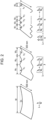
- a sheet with a length of 500 mm in the rolling direction (coil width ⁇ 500 mm L ⁇ sheet thickness) was cut out from the coil and was placed on a surface plate in such a manner that the warp at the ends would face upward.
- the height on the steel sheet was measured with a contact displacement meter by continuously moving the stylus over the width. Based on the results, the steepness as an index of the flatness of the steel sheet shape was measured as illustrated in Fig. 2 .
- the flatness was rated as " ⁇ " when the steepness was more than 0.02, as “o” when the steepness was more than 0.01 and 0.02 or less, and as “ ⁇ ” when the steepness was 0.01 or less.
- the steel sheet was evaluated as "excellent in the flatness in the width direction" when the steepness was 0.02 or less.
- the working embrittlement resistance was evaluated by Charpy test.
- a Charpy test specimen was a 2 mm deep V-notched test piece that was a stack of steel sheets fastened together with bolts to eliminate any gaps between the steel sheets. The number of steel sheets that were stacked was controlled so that the thickness of the stack as the test piece would be closer to 10 mm. When, for example, the sheet thickness was 1.2 mm, eight sheets were stacked to give a 9.6 mm thick test piece. The sheets for stacking into the Charpy test specimen were sampled so that the width direction would be the longitudinal direction.
- the ratio vE 0% /vE 10% of the absorbed impact energy at room temperature of the as-produced (unworked) steel sheet to that of the steel sheet after 10% rolling was measured.
- the working embrittlement resistance was rated as " ⁇ " when vE 0% /vE 10% was less than 0.6, as “o” when vE 0% /vE 10% was 0.6 or more and less than 0.7, and as " ⁇ ” when vE 0% /vE 10% was 0.7 or more.
- the Charpy test specimen was evaluated as "excellent in working embrittlement resistance" when vE 0% /vE 10% was 0.6 or more. Conditions other than those described above conformed to JIS Z 2242: 2018.
Landscapes
- Chemical & Material Sciences (AREA)
- Engineering & Computer Science (AREA)
- Materials Engineering (AREA)
- Mechanical Engineering (AREA)
- Metallurgy (AREA)
- Organic Chemistry (AREA)
- Thermal Sciences (AREA)
- Physics & Mathematics (AREA)
- Crystallography & Structural Chemistry (AREA)
- Chemical Kinetics & Catalysis (AREA)
- Oil, Petroleum & Natural Gas (AREA)
- Heat Treatment Of Sheet Steel (AREA)
- Heat Treatment Of Steel (AREA)
Abstract
Description
- The present invention relates to a high strength steel sheet excellent in tensile strength, El, toughness, flatness in the width direction, and working embrittlement resistance, and to a method for manufacturing the same. The high strength steel sheet of the present invention may be suitably used as structural members, such as automobile parts.
- Steel sheets for automobiles are being increased in strength in order to reduce CO2 emissions by weight reduction of vehicles and to enhance crashworthiness by weight reduction of automobile bodies at the same time, with introduction of new laws and regulations one after another. To increase the strength of automobile bodies, high strength steel sheets having a tensile strength (TS) of 980 MPa or higher grade are increasingly applied to principal structural parts of automobiles.
- High strength steel sheets used in automobiles require excellent press formability. For example, high strength steel sheets with high El are suitably applied to automobile frame parts, such as bumpers. From the point of view of crash safety, excellent toughness and working embrittlement resistance are required.
- Furthermore, high strength steel sheets used in automobiles require high flatness.
Patent Literature 1 describes that warpage of a steel sheet causes operational troubles in forming lines and adversely affects the dimensional accuracy of products. The present inventors carried out extensive studies and have found that the dimensional accuracy of products is affected not only by the warpage of steel sheets but also by the flatness in the width direction that is evaluated as steepness. For example, the steepness in the width direction is suitably 0.02 or less in order to achieve excellent dimensional accuracy. - To meet the above demands, for example, Patent Literature 2 provides a high strength steel sheet having a tensile strength of 1100 MPa or more and being excellent in YR, surface quality, and weldability, and a method for manufacturing the same. However, the technique described in Patent Literature 2 does not take into consideration El, toughness, flatness in the width direction, and working embrittlement resistance.
- Patent Literature 3 provides a hot-dip galvanized steel sheet with excellent press formability and low-temperature toughness that has a tensile strength of 980 MPa or more, and a method for manufacturing the same. While the steel sheet of Patent Literature 3 is improved in embrittlement at low temperatures, the technique does not take into consideration the working embrittlement of the steel sheet or the flatness in the width direction.
-
- PTL 1:
Japanese Patent No. 4947176 - PTL 2:
Japanese Patent No. 6525114 - PTL 3:
Japanese Patent No. 6777272 - NPL 1: Journal of Smart Processing, 2013, Vol. 2, No. 3, pp. 110-118
- The present invention has been developed in view of the circumstances discussed above. Objects of the present invention are therefore to provide a high strength steel sheet having 980 MPa or higher TS and 10% or more El and being excellent in toughness, flatness in the width direction, and working embrittlement resistance; and to provide a method for manufacturing the same.
- The present inventors carried out extensive studies directed to solving the problems described above and have consequently found the following facts.
- (1) 980 MPa or higher TS can be realized by limiting the area fraction of martensite to 60% or more.
- (2) 10% or more El can be achieved by limiting the volume fraction of retained austenite to 3% or more and the area fraction of the total of ferrite and bainitic ferrite to more than 10%.
- (3) Excellent toughness can be realized by limiting the volume fraction of retained austenite to 3% or more.
- (4) Excellent working embrittlement resistance can be achieved by limiting the proportion of a packet having the largest area in a prior austenite grain to 70% by area or less on average.
- (5) Excellent working embrittlement resistance can be realized by limiting the volume fraction of retained austenite to 15% or less and by limiting the proportion of a packet having the largest area in a prior austenite grain to 70% by area or less on average.
- The present invention has been made based on the above findings. Specifically, a summary of configurations of the present invention is as follows.
- [1] A high strength steel sheet having a chemical composition including, in mass%, C: 0.030% or more and 0.500% or less, Si: 0.50% or more and 2.50% or less, Mn: 1.00% or more and 5.00% or less, P: 0.100% or less, S: 0.0200% or less, Al: 1.000% or less, N: 0.0100% or less, and O: 0.0100% or less, a balance being Fe and incidental impurities, the high strength steel sheet being such that in a region at 1/4 sheet thickness, an area fraction of martensite is 60% or more, a volume fraction of retained austenite is 3% or more and 15% or less, an area fraction of a total of ferrite and bainitic ferrite is more than 10%, and an average of proportions of packets having the largest area in prior austenite grains is 70% by area or less of the prior austenite grain.
- [2] The high strength steel sheet according to [1], wherein the chemical composition further includes at least one element selected from, in mass%, Ti: 0.200% or less, Nb: 0.200% or less, V: 0.200% or less, Ta: 0.10% or less, W: 0.10% or less, B: 0.0100% or less, Cr: 1.00% or less, Mo: 1.00% or less, Co: 0.010% or less, Ni: 1.00% or less, Cu: 1.00% or less, Sn: 0.200% or less, Sb: 0.200% or less, Ca: 0.0100% or less, Mg: 0.0100% or less, REM: 0.0100% or less, Zr: 0.100% or less, Te: 0.100% or less, Hf: 0.10% or less, and Bi: 0.200% or less.
- [3] The high strength steel sheet according to [1] or [2], which has a coated layer on a surface of the steel sheet.
- [4] A method for manufacturing the high strength steel sheet according to [1] or [2], the method including providing a cold rolled steel sheet produced by subjecting a steel having the chemical composition to hot rolling, pickling, and cold rolling; annealing the steel sheet by heating at an annealing temperature Ta of 700°C or above and 900°C or below for a holding time at the annealing temperature Ta of 10 seconds or more and 1000 seconds or less; bending and unbending the
steel sheet 1 to 15 times in total with a roll having a radius of 800 mm or less during the annealing; cooling the steel sheet at an average cooling rate of 20°C/s or more in a temperature range from 700°C to 600°C and at an average cooling rate of less than 20°C/s in a temperature range from 499°C to Ms; bending and unbending the steel sheet in the temperature range from 499°C to Ms, 1 to 15 times in total with a roll having a radius of 800 mm or less; cooling the steel sheet at an average cooling rate of 150°C/s or less in a temperature range from Ms to a cooling stop temperature Tb; applying a tension to the steel sheet in the temperature range from Ms to the cooling stop temperature Tb while controlling the tension to 5 MPa or more and 100 MPa or less, the cooling stop temperature Tb being 100°C or above and (Ms - 80°C) or below where Ms is a martensite start temperature (°C) defined by formula (1); and tempering the steel sheet at a tempering temperature of Tb or above and 450°C or below for a holding time at the tempering temperature of 10 seconds or more and 1000 seconds or less,Ms = 519 - 474 × [% C] - 30.4 × × [% Mn] - 12.1 × [% Cr] - 7.5 × [% Mo] - 17.7 × [% Ni] - Ta/80 - [5] The method for manufacturing the high strength steel sheet according to [4], further including performing a coating treatment.
- According to the present invention, a high strength steel sheet can be obtained that has 980 MPa or higher TS and 10% or more El and excels in toughness, flatness in the width direction, and working embrittlement resistance. Furthermore, for example, the high strength steel sheet of the present invention may be applied to automobile structural members to reduce the weight of automobile bodies and thereby to enhance fuel efficiency. Thus, the present invention is highly valuable in industry.
-
- [
Fig. 1] Fig. 1 is a set of views illustrating a structure of a packet having the largest area in a prior austenite grain according to the present invention, and how the proportion of the packet is calculated. - [
Fig. 2] Fig. 2 is a set of views illustrating the concept of the steepness λ in the width direction of a steel sheet according to the present invention, and how the steepness is calculated. - Embodiments of the present invention will be described below.
- First, appropriate ranges of the chemical composition of the high strength steel sheet and the reasons why the chemical composition is thus limited will be described. In the following description, "%" indicating the contents of constituent elements of steel means "mass%" unless otherwise specified.
- Carbon is one of the important basic components of steel. Particularly in the present invention, carbon is an important element that affects the amount of martensite. When the C content is less than 0.030%, the amount of martensite is so small that realizing 980 MPa or higher TS is difficult. When, on the other hand, the C content is more than 0.500%, martensite becomes brittle to cause deterioration in toughness and working embrittlement resistance. Thus, the C content is limited to 0.030% or more and 0.500% or less. The lower limit of the C content is preferably 0.050% or more. The upper limit of the C content is preferably 0.400% or less. The lower limit of the C content is more preferably 0.100% or more. The upper limit of the C content is more preferably 0.350% or less.
- Silicon is one of the important basic components of steel and is an important element that affects TS and the amount of retained austenite. When the Si content is less than 0.50%, the strength of martensite decreases to make it difficult to achieve 980 MPa or higher TS. When, on the other hand, the Si content is more than 2.50%, the amount of retained austenite is increased excessively, and toughness and working embrittlement resistance are lowered. Thus, the Si content is limited to 0.50% or more and 2.50% or less. The lower limit of the Si content is preferably 0.55% or more. The upper limit of the Si content is preferably 2.00% or less. The lower limit of the Si content is more preferably 0.60% or more. The upper limit of the Si content is more preferably 1.80% or less.
- Manganese is one of the important basic components of steel and is an important element that affects the amount of martensite. When the Mn content is less than 1.00%, the amount of martensite is so small that realizing 980 MPa or higher TS is difficult. When, on the other hand, the Mn content is more than 5.00%, martensite becomes brittle to cause deterioration in toughness and working embrittlement resistance. Thus, the Mn content is limited to 1.00% or more and 5.00% or less. The lower limit of the Mn content is preferably 1.50% or more. The upper limit of the Mn content is preferably 4.50% or less. The lower limit of the Mn content is more preferably 2.00% or more. The upper limit of the Mn content is more preferably 4.00% or less.
- Phosphorus is segregated at prior austenite grain boundaries and makes the grain boundaries brittle, thereby lowering the ultimate deformability of steel sheets and causing deterioration in toughness and working embrittlement resistance. Thus, the P content needs to be 0.100% or less. The lower limit of the P content is not particularly specified. In view of the fact that phosphorus is a solid solution strengthening element and can increase the strength of steel sheets, the lower limit is preferably 0.001% or more. For the reasons above, the P content is limited to 0.100% or less. The lower limit of the P content is preferably 0.001% or more. The upper limit of the P content is preferably 0.070% or less.
- Sulfur forms sulfides and lowers the ultimate deformability of steel sheets to cause deterioration in toughness and working embrittlement resistance. Thus, the S content needs to be 0.0200% or less. The lower limit of the S content is not particularly specified but is preferably 0.0001% or more due to production technique limitations. For the reasons above, the S content is limited to 0.0200% or less. The lower limit of the S content is preferably 0.0001% or more. The upper limit of the S content is preferably 0.0050% or less.
- Aluminum forms the oxide and lowers the ultimate deformability of steel sheets to cause deterioration in toughness and working embrittlement resistance. Thus, the Al content needs to be 1.000% or less. The lower limit of the Al content is not particularly specified. In view of the fact that aluminum suppresses the occurrence of carbides during continuous annealing and promotes the formation of retained austenite, the Al content is preferably 0.001% or more. For the reasons above, the Al content is limited to 1.000% or less. The lower limit of the Al content is preferably 0.001% or more. The upper limit of the Al content is preferably 0.500% or less.
- Nitrogen forms nitrides and lowers the ultimate deformability of steel sheets to cause deterioration in toughness and working embrittlement resistance. Thus, the N content needs to be 0.0100% or less. The lower limit of the N content is not particularly specified but the N content is preferably 0.0001% or more due to production technique limitations. For the reasons above, the N content is limited to 0.0100% or less. The lower limit of the N content is preferably 0.0001% or more. The upper limit of the N content is preferably 0.0050% or less.
- Oxygen forms oxides and lowers the ultimate deformability of steel sheets to cause deterioration in toughness and working embrittlement resistance. Thus, the O content needs to be 0.0100% or less. The lower limit of the O content is not particularly specified but the O content is preferably 0.0001% or more due to production technique limitations. For the reasons above, the O content is limited to 0.0100% or less. The lower limit of the O content is preferably 0.0001% or more. The upper limit of the O content is preferably 0.0050% or less.
- The chemical composition of the high strength steel sheet according to an embodiment of the present invention includes the components described above, and the balance is Fe and incidental impurities. Here, the incidental impurities include Zn, Pb, As, Ge, Sr, and Cs. A total of 0.100% or less of these impurities is acceptable.
- In addition to the components in the proportions described above, the high strength steel sheet of the present invention may further include at least one element selected from, in mass%, Ti: 0.200% or less, Nb: 0.200% or less, V: 0.200% or less, Ta: 0.10% or less, W: 0.10% or less, B: 0.0100% or less, Cr: 1.00% or less, Mo: 1.00% or less, Ni: 1.00% or less, Co: 0.010% or less, Cu: 1.00% or less, Sn: 0.200% or less, Sb: 0.200% or less, Ca: 0.0100% or less, Mg: 0.0100% or less, REM: 0.0100% or less, Zr: 0.100% or less, Te: 0.100% or less, Hf: 0.10% or less, and Bi: 0.200% or less. These elements may be contained singly or in combination.
- When the contents of Ti, Nb, and V are each 0.200% or less, coarse precipitates and inclusions will not occur in large amounts and thus will not cause lowering of the ultimate deformability of steel sheets; hence there will be no deterioration in toughness or working embrittlement resistance. Thus, the contents of Ti, Nb, and V are each preferably 0.200% or less. The lower limits of the contents of Ti, Nb, and V are not particularly specified. These elements form fine carbides, nitrides, or carbonitrides during hot rolling or continuous annealing to increase the strength of steel sheets. In view of this fact, the contents of Ti, Nb, and V are each more preferably 0.001% or more. When titanium, niobium, and vanadium are added, the contents thereof are each limited to 0.200% or less for the reasons above. The lower limits of the contents of Ti, Nb, and V, when added, are each more preferably 0.001% or more. The upper limits of the contents of Ti, Nb, and V, when added, are each more preferably 0.100% or less.
- When the contents of Ta and W are each 0.10% or less, coarse precipitates and inclusions will not occur in large amounts and thus will not cause lowering of the ultimate deformability of steel sheets; hence there will be no deterioration in toughness or working embrittlement resistance. Thus, the contents of Ta and W are each preferably 0.10% or less. The lower limits of the contents of Ta and W are not particularly specified. These elements form fine carbides, nitrides, or carbonitrides during hot rolling or continuous annealing to increase the strength of steel sheets. In view of this fact, the contents of Ta and W are each more preferably 0.01% or more. When tantalum and tungsten are added, the contents thereof are each limited to 0.10% or less for the reasons above. The lower limits of the contents of Ta and W, when added, are each more preferably 0.01% or more. The upper limits of the contents of Ta and W, when added, are each more preferably 0.08% or less.
- When the B content is 0.0100% or less, inner cracks that lower the ultimate deformability of steel sheets will not form during casting or hot rolling and thus there will be no deterioration in toughness or working embrittlement resistance. Thus, the B content is preferably 0.0100% or less. The lower limit of the B content is not particularly specified. The B content is more preferably 0.0003% or more in view of the fact that this element is segregated at austenite grain boundaries during annealing and enhances hardenability. When boron is added, the content thereof is limited to 0.0100% or less for the reasons above. The lower limit of the content of B, when added, is more preferably 0.0003% or more. The upper limit of the content of B, when added, is more preferably 0.0080% or less.
- When the contents of Cr, Mo, and Ni are each 1.00% or less, coarse precipitates and inclusions will not occur in increased amounts and thus will not cause lowering of the ultimate deformability of steel sheets; hence there will be no deterioration in toughness or working embrittlement resistance. Thus, the contents of Cr, Mo, and Ni are each preferably 1.00% or less. The lower limits of the contents of Cr, Mo, and Ni are not particularly specified. In view of the fact that these elements enhance hardenability, the contents of Cr, Mo, and Ni are each more preferably 0.01% or more. When chromium, molybdenum, and nickel are added, the contents thereof are each limited to 1.00% or less for the reasons above. The lower limits of the contents of Cr, Mo, and Ni, when added, are each more preferably 0.01% or more. The upper limits of the contents of Cr, Mo, and Ni, when added, are each more preferably 0.80% or less.
- When the Co content is 0.010% or less, coarse precipitates and inclusions will not occur in increased amounts and thus will not cause lowering of the ultimate deformability of steel sheets; hence there will be no deterioration in toughness or working embrittlement resistance. Thus, the Co content is preferably 0.010% or less. The lower limit of the Co content is not particularly specified. In view of the fact that this element enhances hardenability, the Co content is more preferably 0.001% or more. When cobalt is added, the content thereof is limited to 0.010% or less for the reasons above. The lower limit of the content of Co, when added, is more preferably 0.001% or more. The upper limit of the content of Co, when added, is more preferably 0.008% or less.
- When the Cu content is 1.00% or less, coarse precipitates and inclusions will not occur in increased amounts and thus will not cause lowering of the ultimate deformability of steel sheets; hence there will be no deterioration in toughness or working embrittlement resistance. Thus, the Cu content is preferably 1.00% or less. The lower limit of the Cu content is not particularly specified. In view of the fact that this element enhances hardenability, the Cu content is preferably 0.01% or more. When copper is added, the content thereof is limited to 1.00% or less for the reasons above. The lower limit of the content of Cu, when added, is more preferably 0.01% or more. The upper limit of the content of Cu, when added, is more preferably 0.80% or less.
- When the Sn content is 0.200% or less, inner cracks that lower the ultimate deformability of steel sheets will not form during casting or hot rolling and thus there will be no deterioration in toughness or working embrittlement resistance. Thus, the Sn content is preferably 0.200% or less. The lower limit of the Sn content is not particularly specified. The Sn content is more preferably 0.001% or more in view of the fact that tin enhances hardenability (in general, is an element that enhances corrosion resistance). When tin is added, the content thereof is limited to 0.200% or less for the reasons above. The lower limit of the content of Sn, when added, is more preferably 0.001% or more. The upper limit of the content of Sn, when added, is more preferably 0.100% or less.
- When the Sb content is 0.200% or less, coarse precipitates and inclusions will not occur in increased amounts and thus will not cause lowering of the ultimate deformability of steel sheets; hence there will be no deterioration in toughness or working embrittlement resistance. Thus, the Sb content is preferably 0.200% or less. The lower limit of the Sb content is not particularly specified. In view of the fact that this element enables control of the thickness of surface layer softening and the strength, the Sb content is more preferably 0.001% or more. When antimony is added, the content thereof is limited to 0.200% or less for the reasons above. The lower limit of the content of Sb, when added, is more preferably 0.001% or more. The upper limit of the content of Sb, when added, is more preferably 0.100% or less.
- When the contents of Ca, Mg, and REM are each 0.0100% or less, coarse precipitates and inclusions will not occur in increased amounts and thus will not cause lowering of the ultimate deformability of steel sheets; hence there will be no deterioration in toughness or working embrittlement resistance. Thus, the contents of Ca, Mg, and REM are each preferably 0.0100% or less. The lower limits of the contents of Ca, Mg, and REM are not particularly specified. In view of the fact that these elements change the shapes of nitrides and sulfides into spheroidal and enhance the ultimate deformability of steel sheets, the contents of Ca, Mg, and REM are each more preferably 0.0005% or more. When calcium, magnesium, and rare earth metal(s) are added, the contents thereof are each limited to 0.0100% or less for the reasons above. The lower limits of the contents of Ca, Mg, and REM, when added, are each more preferably 0.0005% or more. The upper limits of the contents of Ca, Mg, and REM, when added, are each more preferably 0.0050% or less.
- When the contents of Zr and Te are each 0.100% or less, coarse precipitates and inclusions will not occur in increased amounts and thus will not cause lowering of the ultimate deformability of steel sheets; hence there will be no deterioration in toughness or working embrittlement resistance. Thus, the contents of Zr and Te are each preferably 0.100% or less. The lower limits of the contents of Zr and Te are not particularly specified. In view of the fact that these elements change the shapes of nitrides and sulfides into spheroidal and enhance the ultimate deformability of steel sheets, the contents of Zr and Te are each more preferably 0.001% or more. When zirconium and tellurium are added, the contents thereof are each limited to 0.100% or less for the reasons above. The lower limits of the contents of Zr and Te, when added, are each more preferably 0.001% or more. The upper limits of the contents of Zr and Te, when added, are each more preferably 0.080% or less.
- When the Hf content is 0.10% or less, coarse precipitates and inclusions will not occur in increased amounts and thus will not cause lowering of the ultimate deformability of steel sheets; hence there will be no deterioration in toughness or working embrittlement resistance. Thus, the Hf content is preferably 0.10% or less. The lower limit of the Hf content is not particularly specified. In view of the fact that this element changes the shapes of nitrides and sulfides into spheroidal and enhances the ultimate deformability of steel sheets, the Hf content is more preferably 0.01% or more. When hafnium is added, the content thereof is limited to 0.10% or less for the reasons above. The lower limit of the content of Hf, when added, is more preferably 0.01% or more. The upper limit of the content of Hf, when added, is more preferably 0.08% or less.
- When the Bi content is 0.200% or less, coarse precipitates and inclusions will not occur in increased amounts and thus will not cause lowering of the ultimate deformability of steel sheets; hence there will be no deterioration in toughness or working embrittlement resistance. Thus, the Bi content is preferably 0.200% or less. The lower limit of the Bi content is not particularly specified. In view of the fact that this element reduces the occurrence of segregation, the Bi content is more preferably 0.001% or more. When bismuth is added, the content thereof is limited to 0.200% or less for the reasons above. The lower limit of the content of Bi, when added, is more preferably 0.001% or more. The upper limit of the content of Bi, when added, is more preferably 0.100% or less.
- When the content of any of Ti, Nb, V, Ta, W, B, Cr, Mo, Ni, Co, Cu, Sn, Sb, Ca, Mg, REM, Zr, Te, Hf, and Bi is below the preferred lower limit, the element does not impair the advantageous effects of the present invention and is regarded as an incidental impurity.
- Next, the steel microstructure of the high strength steel sheet of the present invention will be described.
- This configuration is a very important requirement that constitutes the present invention. 980 MPa or higher TS can be achieved when the area fraction of martensite is 60% or more. Thus, the area fraction of martensite is limited to 60% or more. The area fraction is preferably 62% or more, and more preferably 64% or more.
- This configuration is a very important requirement that constitutes the present invention. When the volume fraction of retained austenite is less than 3%, it is difficult to realize 10% or more El and it is also difficult to attain excellent toughness because the toughness enhancement effect by retained austenite cannot be obtained. When the amount of retained austenite is more than 15%, retained austenite is excessively transformed into hard martensite at the time of working and the steel sheet is lowered in ultimate deformability and will not attain excellent working embrittlement resistance. Thus, the retained austenite is limited to 3% or more and 15% or less. The lower limit of the amount of retained austenite is preferably 5% or more. The upper limit of the amount of retained austenite is preferably 140 or less. The lower limit of the amount of retained austenite is more preferably 7% or more. The upper limit of the amount of retained austenite is more preferably 13% or less.
- Here, retained austenite is measured as follows. The steel sheet is polished to expose a face 0.1 mm below 1/4 sheet thickness and is thereafter further chemically polished to expose a face 0.1 mm below the face exposed above. The face is analyzed with an X-ray diffractometer using CoKα radiation to determine the integral intensity ratios of the diffraction peaks of {200}, {220}, and {311} planes of fcc iron and {200}, {211}, and {220} planes of bcc iron. Nine integral intensity ratios thus obtained are averaged to determine retained austenite.
- This configuration is a very important requirement that constitutes the present invention. When the total amount of ferrite and bainitic ferrite is 10% or less, it is difficult to achieve 10% or more El. Thus, the total amount of ferrite and bainitic ferrite is limited to more than 10%. The total amount is preferably 120 or more, and more preferably 13% or more. The upper limit of the total amount of ferrite and bainitic ferrite is not particularly limited.
- Here, the total amount of ferrite and bainitic ferrite is measured as follows. A longitudinal cross section of the steel sheet is polished and is etched with 3 vol% Nital. A portion at 1/4 sheet thickness (a location corresponding to 1/4 of the sheet thickness in the depth direction from the steel sheet surface) is observed using SEM in 10 fields of view at a magnification of ×2000. In the microstructure images, ferrite and bainitic ferrite are recessed structures having a flat interior and containing no inner carbides. The values thus obtained are averaged to determine the total amount of ferrite and bainitic ferrite.
- The amount of martensite is measured as follows. The amount of martensite can be determined by measuring the amounts of retained austenite, ferrite, and bainitic ferrite based on the methods described above, and subtracting the total thereof from 100%. Thus, the amount of martensite in the present invention includes both quenched martensite and tempered martensite. Because the volume fraction of retained austenite is almost equal to the area fraction, the amount is subtracted as such from 100% together with the amounts of ferrite and bainitic ferrite expressed in area fraction.
- This configuration is a very important requirement that constitutes the present invention. The proportion of a packet having the largest area in a prior austenite grain affects the flatness in the width direction and the working embrittlement resistance. As illustrated in
Fig. 1 , a prior austenite grain contains up to four kinds of packets distinguished by crystal habit plane formed by transformation. The packet having the largest area in a prior austenite grain is the packet that occupies the largest area among such packets. - The proportion of one packet in a prior austenite grain is determined by dividing the area of the packet of interest by the area of the whole prior austenite grain.
- As a result of extensive studies, the present inventors have found that strain among the packets is reduced and the flatness in the width direction is improved by lowering the proportion of a packet having the largest area in a prior austenite grain. The present inventors have also found that lowering the proportion of a packet having the largest area in a prior austenite grain leads to a fine microstructure and suppresses crack propagation, thereby enhancing the working embrittlement resistance of the steel sheet. Thus, the average of the proportions of packets having the largest area in prior austenite grains is limited to 70% or less. The average proportion is preferably 60% or less. The lower limit of the average proportion of packets having the largest area in prior austenite grains is not particularly limited. The grains contain up to four kinds of packets. When four packets are evenly distributed, the proportion of a packet having the largest area in the prior austenite grain is 25%. Thus, the lower limit of the average proportion of packets having the largest area in prior austenite grains is preferably 25% or more. However, the lower limit of the average proportion is not necessarily limited thereto.
- Here, the average proportion of packets having the largest area in prior austenite grains is measured as follows. First, a test specimen for microstructure observation is sampled from the cold rolled steel sheet. Next, the sampled test specimen is polished by vibration polishing with colloidal silica to expose a cross section in the rolling direction (a longitudinal cross section) for use as observation surface. The observation surface is specular. Next, electron backscatter diffraction (EBSD) measurement is performed with respect to a portion at 1/4 sheet thickness (a location corresponding to 1/4 of the sheet thickness in the depth direction from the steel sheet surface) to obtain local crystal orientation data. Here, the SEM magnification is ×1000, the step size is 0.2 um, the measured region is 80 um square, and the WD is 15 mm. The local orientation data obtained is analyzed with OIM Analysis 7 (OIM), and a map (a CP map) that shows close-packed plane groups (CP groups) with different colors is created using the method described in
Non Patent Literature 1. In the present invention, a packet is defined as a region or regions belonging to the same CP group. From the CP map obtained, the area of the packet having the largest area is determined and is divided by the area of the whole prior austenite grain to give the proportion of the packet having the largest area in the prior austenite grain. This analysis is performed with respect to 10 or more adjacent prior austenite grains, and the results are averaged to give the average proportion of packets having the largest area in prior austenite grains. - Next, a manufacturing method of the present invention will be described.
- In the present invention, a steel material (a steel slab) may be obtained by any known steelmaking method without limitation, such as a converter or an electric arc furnace. To prevent macro-segregation, the steel slab (the slab) is preferably produced by a continuous casting method.
- In the present invention, the slab heating temperature, the slab soaking holding time, and the coiling temperature in hot rolling are not particularly limited. For example, the steel slab may be hot rolled in such a manner that the slab is heated and is then rolled, that the slab is subjected to hot direct rolling after continuous casting without being heated, or that the slab is subjected to a short heat treatment after continuous casting and is then rolled. The slab heating temperature, the slab soaking holding time, the finish rolling temperature, and the coiling temperature in hot rolling are not particularly limited. The lower limit of the slab heating temperature is preferably 1100°C or above. The upper limit of the slab heating temperature is preferably 1300°C or below. The lower limit of the slab soaking holding time is preferably 30 minutes or more. The upper limit of the slab soaking holding time is preferably 250 minutes or less. The lower limit of the finish rolling temperature is preferably Ar3 transformation temperature or above. Furthermore, the lower limit of the coiling temperature is preferably 350°C or above. The upper limit of the coiling temperature is preferably 650°C or below.
- The hot rolled steel sheet thus produced is pickled. Pickling can remove oxides on the steel sheet surface and is thus important to ensure good chemical convertibility and a high quality of coating in the final high strength steel sheet. Pickling may be performed at a time or several. The hot rolled sheet that has been pickled may be cold rolled directly or may be subjected to heat treatment before cold rolling.
- The rolling reduction in cold rolling and the sheet thickness after rolling are not particularly limited. The lower limit of the rolling reduction is preferably 30% or more. The upper limit of the rolling reduction is preferably 80% or less. The advantageous effects of the present invention may be obtained without any limitations on the number of rolling passes and the rolling reduction in each pass.
- The cold rolled steel sheet obtained as described above is annealed. Annealing conditions are as follows.
- When the annealing temperature Ta is below 700°C, the amount of martensite is so small that realizing 980 MPa or higher TS is difficult. When, on the other hand, the annealing temperature is above 900°C, the total amount of ferrite and bainitic ferrite decreases to make it difficult to achieve 10% or more El. Thus, the annealing temperature is limited to 700°C or above and 900°C or below. The lower limit of the annealing temperature is preferably 750°C or above. The upper limit of the annealing temperature is preferably 870°C or below.
- When the holding time at the annealing temperature Ta is less than 10 seconds, the amount of martensite is so small that realizing 980 MPa or higher TS is difficult. When, on the other hand, the holding time at the annealing temperature Ta is more than 1000 seconds, the total amount of ferrite and bainitic ferrite decreases to make it difficult to achieve 10% or more El. Thus, the holding time at the annealing temperature Ta is limited to 10 seconds or more and 1000 seconds or less. The lower limit of the holding time at the annealing temperature Ta is preferably 50 seconds or more. The upper limit of the holding time at the annealing temperature Ta is preferably 500 seconds or less.
- As a result of extensive studies, the present inventors have found that bending and unbending of the steel sheet during annealing affects the proportion of a packet having the largest area in a prior austenite grain. When the steel sheet being annealed is not subjected to bending and unbending with a roll having a radius of 800 mm or less, the amount of nucleation sites for martensite transformation is reduced. Consequently, the average proportion of packets having the largest area in prior austenite grains exceeds 70%, and the flatness in the width direction and also the working embrittlement resistance are deteriorated. When, on the other hand, the steel sheet being annealed is subjected to bending and unbending 16 times or more with a roll having a radius of 800 mm or less, the steel sheet is deteriorated in ultimate deformability and also in working embrittlement resistance. Thus, in the annealing, the total count of bending and unbending with a roll having a radius of 800 mm or less is limited to 1 or more and 15 or less. The radius of the roll is preferably 600 mm or less. The lower limit of the total count of bending and unbending is preferably 3 or more. The upper limit of the total count of bending and unbending is preferably 10 or less. The lower limit of the radius of the roll is not necessarily limited but is preferably 50 mm or more.
- Incidentally, "bending and unbending" is a treatment that bends the steel sheet with a roll in one direction according to a known technique and unbends the steel sheet in the opposite direction to cancel the bend. Bending and unbending are not counted in pairs. That is, each bending is counted one and each unbending is counted one.
- As a result of extensive studies, the present inventors have found that the average cooling rate in the temperature range from 700°C to 600°C affects the proportion of a packet having the largest area in a prior austenite grain. When the average cooling rate in the temperature range from 700°C to 600°C is less than 20°C/s, the effects imparted by bending and unbending of the steel sheet during annealing are lowered and the amount of nucleation sites for martensite transformation is reduced. Consequently, the average proportion of packets having the largest area in prior austenite grains exceeds 70%, and the flatness in the width direction and also the working embrittlement resistance are deteriorated. Thus, the average cooling rate from 750°C to 600°C is limited to 20°C/s or more and is preferably 30°C/s or more. The upper limit is not necessarily limited but is preferably 100°C/s or less.
- The average cooling rate in the temperature range from 499°C to Ms affects the total area fraction of ferrite and bainitic ferrite. When the average cooling rate in the temperature range from 499°C to Ms is 20°C/s or more, the total amount of ferrite and bainitic ferrite decreases to make it difficult to achieve 10% or more El. Thus, the average cooling rate in the temperature range from 499°C to Ms is limited to less than 20°C/s. The average cooling rate is preferably 18°C/s or less. The lower limit is not necessarily limited but is preferably 5°C/s or more.
- The martensite start temperature Ms (°C) is defined by the following formula (1):
Ms = 519 - 474 × [% C] - 30.4 × [% Mn] - 12.1 × [% Cr] - 7.5 × [% Mo] - 17.7 × [% Ni] - Ta/80 - [The steel sheet in the temperature range from 499°C to Ms is bent and unbent 1 to 15 times in total with a roll having a radius of 800 mm or less.]
- As a result of extensive studies, the present inventors have found that bending and unbending of the steel sheet in the temperature range from 499°C to Ms affects the proportion of a packet having the largest area in a prior austenite grain. When the steel sheet in the temperature range from 499°C to Ms is not subjected to bending and unbending with a roll having a radius of 800 mm or less, the amount of martensite nucleation sites is reduced. Consequently, the average proportion of packets having the largest area in prior austenite grains exceeds 70%, and the flatness in the width direction and also the working embrittlement resistance are deteriorated. When, on the other hand, the steel sheet in the temperature range from 499°C to Ms is subjected to bending and unbending 16 times or more with a roll having a radius of 800 mm or less, the steel sheet is deteriorated in ultimate deformability and also in working embrittlement resistance. Thus, the total count of bending and unbending in the temperature range from 499°C to Ms with a roll having a radius of 800 mm or less is limited to 1 or more and 15 or less. The radius of the roll is preferably 600 mm or less. The lower limit of the total count of bending and unbending is preferably 3 or more. The lower limit of the total count of bending and unbending is preferably 10 or less. The lower limit of the radius of the roll is not necessarily limited but is preferably 50 mm or more.
- As a result of extensive studies, the present inventors have found that the average cooling rate in the temperature range from Ms to the cooling stop temperature Tb affects the proportion of a packet having the largest area in a prior austenite grain. When the average cooling rate in the temperature range from Ms to the cooling stop temperature Tb is more than 150°C/s, the martensite transformation rate is so fast that a packet grows fast easily. Consequently, the average proportion of packets having the largest area in prior austenite grains exceeds 70%, and the flatness in the width direction and also the working embrittlement resistance are deteriorated. Thus, the average cooling rate in the temperature range from Ms to the cooling stop temperature Tb is limited to 150°C/s or less. The average cooling rate is preferably 120°C/s or less. The lower limit is not necessarily limited but is preferably 5°C/s or more.
- As a result of extensive studies, the present inventors have found that the application of tension to the steel sheet in the temperature range from Ms to the cooling stop temperature Tb affects the proportion of a packet having the largest area in a prior austenite grain. When the tension applied to the steel sheet in the temperature range from Ms to the cooling stop temperature Tb is less than 5 MPa, the amount of martensite nucleation sites is reduced. Consequently, the average proportion of packets having the largest area in prior austenite grains exceeds 70%, and the flatness in the width direction and also the working embrittlement resistance are deteriorated. When, on the other hand, more than 100 MPa tension is applied to the steel sheet in the temperature range from Ms to the cooling stop temperature Tb, the total amount of ferrite and bainitic ferrite is excessively increased and thus the amount of martensite decreases to make it difficult to realize 980 MPa or higher TS. Thus, the tension applied to the steel sheet in the temperature range from Ms to the cooling stop temperature Tb is limited to 5 MPa or more and 100 MPa or less. The lower limit of the tension applied to the steel sheet in the temperature range from Ms to the cooling stop temperature Tb is preferably 6 MPa or more. The upper limit of the tension applied to the steel sheet in the temperature range from Ms to the cooling stop temperature Tb is preferably 50 MPa or less. The tension is applied in a usual manner. As an example, the tension may be applied by controlling the roll speeds of the rolls in the furnace.
- While the bending and unbending process increases the number of nucleation sites that are martensite start sites, the tension application process produces different effects by promoting martensite transformation itself.
- When the cooling stop temperature Tb is below 100°C, the amount of retained austenite decreases and bendability is lowered. When, on the other hand, the cooling stop temperature Tb is above (Ms - 80°C), the amount of retained austenite is excessively increased and the prior austenite grain size is excessively enlarged to cause deterioration in working embrittlement resistance. Thus, the cooling stop temperature Tb is limited to 100°C or above and (Ms - 80°C) or below. The lower limit of the cooling stop temperature Tb is preferably 120°C or above. The upper limit of the cooling stop temperature Tb is preferably (Ms - 100°C) or below.
- After the cooling is stopped at the cooling stop temperature Tb, the steel sheet is held at the temperature or is reheated and held at a temperature of 450°C or below to stabilize retained austenite. When the tempering temperature is below Tb, retained austenite cannot be obtained as desired; consequently El is lowered and excellent toughness is hardly obtained. When the tempering temperature is above 450°C, martensite is excessively tempered to make it difficult to achieve 980 MPa or higher TS. Thus, the tempering temperature is limited to Tb or above and 450°C or below. The lower limit of the tempering temperature is preferably (Tb + 10°C) or above. The upper limit of the tempering temperature is preferably 420°C or below.
- When the holding time at the tempering temperature is less than 10 seconds, austenite stabilization is insufficient and retained austenite cannot be obtained as desired; consequently El is lowered and excellent toughness is hardly obtained. When the holding time at the tempering temperature is more than 1000 seconds, martensite is excessively tempered to make it difficult to achieve 980 MPa or higher TS. Thus, the holding time at the tempering temperature is limited to 10 seconds or more and 1000 seconds or less. The lower limit of the holding time at the tempering temperature is preferably 50 seconds or more. The upper limit of the holding time at the tempering temperature is preferably 800 seconds or less.
- Post-temper cooling is not particularly limited and the steel sheet may be cooled to a desired temperature in an appropriate manner. Incidentally, the desired temperature is preferably about room temperature.
- Furthermore, the high strength steel sheet described above may be worked under conditions where the amount of equivalent plastic strain is 0.10% or more and 5.00% or less. The working may be followed by reheating at 100°C or above and 400°C or below.
- When the high strength steel sheet is a product that is traded, the steel sheet is usually traded after being cooled to room temperature.
- The high strength steel sheet may be subjected to coating treatment during annealing or after annealing.
- For example, the coating treatment during annealing may be hot-dip galvanizing treatment performed when the annealed steel sheet is being cooled or has been cooled from 700°C to 600°C at an average cooling rate of 20°C/s or more. The hot-dip galvanizing treatment may be followed by alloying. For example, the coating treatment after annealing may be Zn-Ni electrical alloy coating treatment or pure Zn electroplated coating treatment performed after tempering. A coated layer may be formed by electroplated coating, or hot-dip zinc-aluminum-magnesium alloy coating may be applied. While the coating treatment has been described above focusing on zinc coating, the types of coating metals, such as Zn coating and Al coating, are not particularly limited. Other conditions in the manufacturing method are not particularly limited. From the point of view of productivity, the series of treatments including annealing, hot-dip galvanizing, and alloying treatment of the coated zinc layer is preferably performed on hot-dip galvanizing line CGL (continuous galvanizing line). To control the coating weight of the coated layer, the hot-dip galvanizing treatment may be followed by wiping. Conditions for operations, such as coating, other than those conditions described above may be determined in accordance with the usual hot-dip galvanizing technique.
- After the coating treatment after annealing, the steel sheet may be worked again under conditions where the amount of equivalent plastic strain is 0.10% or more and 5.00 or less. The working may be followed by reheating at 100°C or above and 400°C or below.
- Steels having a chemical composition described in Table 1 and 2, with the balance being Fe and incidental impurities, were smelted in a converter and were continuously cast into slabs. Next, the slabs obtained were heated, hot rolled, pickled, cold rolled, and subjected to annealing treatment described in Table 3 and 4. High strength cold rolled steel sheets having a sheet thickness of 0.6 to 2.2 mm were thus obtained. During annealing, the steel sheet was subjected to bending and unbending with a roll having a radius of 300 mm. In the temperature range from 499°C to Ms, the steel sheet was subjected to bending and unbending with a roll having a radius of 300 mm. Incidentally, some of the steel sheets were subjected to coating treatment during or after annealing.
- The high strength cold rolled steel sheets obtained as described above were used as test steels. Tensile characteristics, flatness in the width direction, toughness, and working embrittlement resistance were evaluated in accordance with the following test methods.
[Table 1] Steels Chemical composition (mass%) C Si Mn P S N O Al Ti B Nb Cu Others A 0.172 1.37 2.54 0.013 0.0014 0.005 0.005 0.039 INV. EX. B 0.157 1.07 2.86 0.005 0.0011 0.003 0.005 0.028 INV. EX. C 0.175 1.33 2.42 0.014 0.0007 0.004 0.002 0.031 INV. EX. D 0.172 1.14 2.80 0.009 0.0013 0.004 0.005 0.060 INV. EX. E 0.161 1.10 2.85 0.006 0.0012 0.006 0.007 0.049 INV. EX. F 0.037 1.01 2.66 0.010 0.0009 0.003 0.004 0.042 INV. EX. G 0.028 1.10 2.55 0.007 0.0006 0.006 0.007 0.023 COMP. EX. H 0.461 1.33 2.43 0.012 0.0009 0.002 0.004 0.032 INV. EX. I 0.505 1.38 2.83 0.011 0.0007 0.004 0.002 0.015 COMP. EX. J 0.182 0.58 2.81 0.015 0.0006 0.005 0.002 0.037 INV. EX. K 0.179 0.42 2.45 0.011 0.0014 0.003 0.005 0.044 COMP. EX. L 0.180 2.34 2.64 0.008 0.0014 0.003 0.003 0.059 INV. EX. M 0.172 2.54 2.74 0.009 0.0008 0.005 0.005 0.024 COMP. EX. N 0.165 1.15 1.05 0.013 0.0007 0.003 0.002 0.046 INV. EX. O 0.170 1.29 0.95 0.011 0.0013 0.005 0.006 0.025 COMP. EX. P 0.163 1.27 4.96 0.006 0.0008 0.003 0.005 0.018 INV. EX. Q 0.177 1.09 5.16 0.008 0.0013 0.005 0.005 0.013 COMP. EX. R 0.171 1.14 2.73 0.097 0.0008 0.001 0.005 0.038 INV. EX. S 0.180 1.38 2.50 0.109 0.0012 0.004 0.004 0.048 COMP. EX. T 0.184 1.39 2.82 0.012 0.0195 0.006 0.004 0.033 INV. EX. U 0.160 1.24 2.58 0.011 0.0204 0.004 0.004 0.042 COMP. EX. V 0.157 1.38 2.80 0.009 0.0012 0.004 0.005 0.924 INV. EX. W 0.166 1.36 2.47 0.011 0.0014 0.002 0.004 1.049 COMP. EX. X 0.187 1.25 2.61 0.010 0.0006 0.0090 0.005 0.013 INV. EX. Y 0.186 1.05 2.65 0.010 0.0014 0.0110 0.005 0.059 COMP. EX. Z 0.167 1.34 2.87 0.008 0.0011 0.006 0.0090 0.026 INV. EX. AA 0.180 1.33 2.65 0.015 0.0009 0.007 0.0110 0.026 COMP. EX. AB 0.176 1.24 2.77 0.007 0.0012 0.004 0.007 0.047 INV. EX. AC 0.188 1.22 2.68 0.006 0.0011 0.005 0.007 0.042 0.003 INV. EX. AD 0.152 1.14 2.71 0.010 0.0014 0.002 0.003 0.054 0.196 INV. EX. AE 0.156 1.18 2.46 0.011 0.0006 0.007 0.004 0.035 0.204 COMP. EX. AF 0.183 1.14 2.47 0.007 0.0015 0.005 0.004 0.048 0.0003 INV. EX. AG 0.154 1.18 2.77 0.009 0.0011 0.006 0.004 0.027 0.0075 INV. EX. AH 0.183 1.34 2.86 0.009 0.0007 0.003 0.004 0.029 0.0106 COMP. EX. AI 0.178 1.27 2.89 0.009 0.0010 0.002 0.006 0.020 0.001 INV. EX. AJ 0.164 1.16 2.51 0.011 0.0005 0.002 0.002 0.035 0.183 INV. EX. AK 0.167 1.08 2.55 0.014 0.0006 0.004 0.004 0.055 0.204 COMP. EX. AL 0.154 1.04 2.67 0.005 0.0015 0.002 0.003 0.035 0.02 INV. EX. AM 0.176 1.20 2.47 0.005 0.0011 0.004 0.005 0.053 0.95 INV. EX. Underlines indicate being outside the range of the present invention. [Table 2] Steels Chemical composition (mass%) C Si Mn P S N O Al Ti B Nb Cu Others AN 0.178 1.22 2.78 0.009 0.0011 0.004 0.007 0.035 1.05 COMP. EX. AO 0.177 1.03 2.46 0.014 0.0012 0.006 0.002 0.035 V:0.126 INV. EX. AP 0.166 1.06 2.50 0.006 0.0014 0.002 0.003 0.045 Ta:0.01 INV. EX. AQ 0.161 1.14 2.62 0.005 0.0012 0.001 0.006 0.037 W:0.04 INV. EX. AR 0.163 1.15 2.88 0.009 0.0013 0.006 0.007 0.025 Cr:0.71 INV. EX. AS 0.155 1.08 2.87 0.012 0.0007 0.003 0.002 0.023 Mo:0.07 INV. EX. AT 0.173 1.24 2.53 0.013 0.0013 0.003 0.002 0.036 Co:0.008 INV. EX. AU 0.178 1.15 2.86 0.007 0.0011 0.004 0.005 0.056 Ni:0.18 INV. EX. AV 0.167 1.01 2.47 0.005 0.0014 0.004 0.001 0.051 Sn:0.131 INV. EX. AW 0.173 1.06 2.42 0.006 0.0011 0.003 0.004 0.037 Sb:0.026 INV. EX. AX 0.189 1.01 2.73 0.012 0.0008 0.005 0.007 0.054 Ca:0.0073 INV. EX. AY 0.184 1.15 2.82 0.007 0.0006 0.003 0.006 0.022 Mg:0.0014 INV. EX. AZ 0.184 1.04 2.52 0.012 0.0014 0.002 0.006 0.011 Zr:0.072 INV. EX. BA 0.158 1.39 2.55 0.014 0.0013 0.006 0.007 0.027 Te:0.024 INV. EX. BB 0.190 1.36 2.89 0.013 0.0011 0.006 0.005 0.053 Hf:0.10 INV. EX. BC 0.164 1.12 2.74 0.008 0.0011 0.003 0.003 0.039 REM:0.0097 INV. EX. BD 0.183 1.06 2.80 0.011 0.0012 0.002 0.005 0.011 Bi:0.153 INV. EX. BE 0.158 1.33 2.65 0.007 0.0015 0.006 0.004 0.033 Zn:0.074 INV. EX. BF 0.176 1.26 2.49 0.010 0.0007 0.004 0.006 0.014 Pb:0.076 INV. EX. BG 0.159 1.08 2.68 0.012 0.0008 0.001 0.004 0.052 As:0.096 INV. EX. BH 0.178 1.15 2.53 0.011 0.0008 0.004 0.002 0.019 Ge:0.022 INV. EX. BI 0.178 1.38 2.75 0.006 0.0012 0.001 0.001 0.043 Sr:0.012 INV. EX. BJ 0.167 1.02 2.41 0.014 0.0015 0.006 0.001 0.036 Cs:0.047 INV. EX. BK 0.156 1.18 2.55 0.014 0.0010 0.003 0.006 0.049 INV. EX. BL 0.150 1.02 2.88 0.014 0.0007 0.006 0.005 0.040 INV. EX. BM 0.187 1.21 2.67 0.015 0.0013 0.006 0.006 0.014 INV. EX. BN 0.161 1.32 2.57 0.014 0.0009 0.006 0.006 0.047 INV. EX. BO 0.175 1.02 2.73 0.011 0.0008 0.001 0.005 0.047 INV. EX. Underlines indicate being outside the range of the present invention. [Table 3] Nos. Steels Annealing temp. Ta (°C) Annealing time (s) Count of bending and unbending during annealing (times) Average cooling rate in temperature range of 700-600°C (°C/s) Average cooling rate in temperature range of 499°C-Ms (°C/s) Count of bending and unbending in temperature range of 499°C-Ms (times) Ms (°C) (Ms-80) (°C) Cooling stop temp. Tb (°C) Average cooling rate in temperature range of Ms-Tb (°C/s) Tension in temperature range of Ms-Tb (MPa) Tempering temp. (°C) Tempering time (s) Type" 1 A 837 142 10 80 13 3 350 270 232 16 13 333 223 CR INV. EX. 2 B 840 129 10 68 13 3 347 267 202 14 8 258 131 CR INV. EX. 3 B 740 81 10 63 15 3 348 268 231 16 10 327 119 CR INV. EX. 4 B 697 74 10 60 11 3 349 269 222 19 9 290 144 CR COMP. EX. 5 B 890 180 10 51 15 3 347 267 202 19 16 330 104 CR INV. EX. 6 B 901 132 10 74 12 3 346 266 226 19 9 348 228 CR COMP. EX. 7 B 828 23 10 59 12 3 347 267 198 14 10 282 119 CR INV. EX. 8 B 842 6 10 55 10 3 347 267 206 18 13 261 224 CR COMP. EX. 9 B 808 809 10 53 11 3 348 268 200 14 8 284 188 CR INV. EX. 10 B 845 1020 10 63 13 3 347 267 206 17 18 268 297 CR COMP. EX. 11 B 829 131 1 65 13 3 347 267 205 13 13 308 179 CR INV. EX. 12 B 827 186 0 60 13 3 347 267 218 13 15 264 129 CR COMP. EX. 13 B 847 110 15 59 10 3 347 267 200 11 17 326 235 CR INV. EX. 14 B 842 50 15 64 12 3 347 267 205 16 12 294 184 CR INV. EX. 15 B 830 131 3 22 11 3 347 267 202 14 9 310 278 CR INV. EX. 16 B 839 176 3 12 12 3 347 267 233 18 11 274 253 CR COMP. EX. 17 B 849 99 3 73 11 3 347 267 216 11 15 257 132 CR INV. EX. 18 B 808 89 3 67 12 3 348 268 205 17 8 326 262 CR INV. EX. 19 B 803 100 3 73 19 3 348 268 215 17 13 326 156 CR INV. EX. 20 B 812 74 3 67 28 3 347 267 230 17 12 302 295 CR COMP. EX. 21 B 802 133 3 75 14 3 348 268 198 103 18 279 219 CR INV. EX. 22 B 842 161 3 58 12 3 347 267 219 14 13 219 246 CR INV. EX. 23 B 811 82 3 73 12 1 348 268 234 16 12 251 278 CR INV. EX. 24 B 824 105 3 77 12 0 347 267 198 14 10 275 282 CR COMP. EX. 25 B 841 73 3 63 12 15 347 267 201 17 15 338 238 CR INV. EX. 26 B 827 165 3 54 15 15 347 267 211 13 17 313 101 CR INV. EX. 27 B 803 173 3 51 15 3 348 268 104 14 10 312 265 CR INV. EX. 28 B 842 98 3 79 15 3 347 267 95 17 13 313 280 CR COMP. EX. 29 B 818 187 3 75 14 3 347 267 267 16 15 284 189 CR INV. EX. 30 B 828 71 3 61 12 3 347 267 272 11 10 309 259 CR COMP. EX. 31 B 833 193 3 75 11 3 347 267 222 13 12 285 278 CR INV. EX. 32 B 825 129 3 55 14 3 347 267 232 13 15 296 262 CR INV. EX. 33 B 819 65 3 67 14 3 347 267 220 149 17 311 106 CR INV. EX. 34 B 817 125 10 64 12 3 347 267 216 155 17 344 274 CR COMP. EX. 35 B 841 123 10 58 12 3 347 267 222 15 5 293 258 CR INV. EX. 36 B 803 63 10 69 12 3 348 268 201 14 4 338 114 CR COMP. EX. 37 B 823 66 10 69 14 3 347 267 216 18 99 276 184 CR INV. EX. 38 B 847 166 10 60 13 3 347 267 219 16 104 347 137 CR COMP. EX. 39 B 806 72 10 64 15 3 348 268 223 14 14 223 242 CR INV. EX. 40 B 825 120 10 66 13 3 347 267 206 13 15 206 106 CR INV. EX. 41 B 844 170 10 74 12 3 347 267 226 19 13 420 151 CR INV. EX. 42 B 810 124 10 75 13 3 348 268 211 18 17 448 273 CR INV. EX. 43 B 846 111 10 68 11 10 347 267 235 19 8 282 23 CR INV. EX. 44 B 821 167 3 73 13 10 347 267 237 17 11 303 3 CR COMP. EX. 45 B 830 71 3 71 13 10 347 267 203 14 15 347 964 CR INV. EX. 46 B 831 196 3 77 14 10 347 267 224 16 8 327 824 CR INV. EX. 47 B 827 80 3 69 14 10 347 267 210 15 8 320 266 CR INV. EX. 48 B 830 158 3 62 14 10 347 267 200 95 12 285 101 CR INV. EX. 49 C 841 123 3 58 11 10 352 272 202 105 11 288 214 CR INV. EX. 50 D 826 188 3 59 11 10 342 262 201 16 12 321 103 CR INV. EX. 51 E 809 134 3 56 12 3 346 266 210 11 12 287 281 CR INV. EX. 52 F 802 157 3 77 12 3 411 331 269 10 9 345 270 CR INV. EX. 53 G 849 143 3 55 13 3 418 338 279 14 14 349 122 CR COMP. EX. Underlines indicate being outside the range of the present invention.
(*)CR: cold rolled steel sheet (no coating), GI: hot-dip galvanized steel sheet (no alloying of zinc coating), GA: galvannealed steel sheet, EG: electrogalvanized steel sheet[Table 4] Nos. Steels Annealing temp. Ta (°C) Annealing time (s) Count of bending and unbending durin annealing (times) Average cooling rate in temperature range of 700-600°C (°C/s) Average cooling rate in temperature range of 499°C-Ms (°C/s) Count of bending and unbending in temperature range of 499°C-Ms (times) Ms (°C) (Ms-80) (°C) Cooling stop temp. Tb (°C) Average cooling rate in temperature range of Ms-Tb (°C/s) Tension in temperature range of Ms-Tb (MPa) Tempering temp. (°C) Tempering time (s) Type* 54 H 816 172 3 56 13 3 216 136 110 12 14 318 158 CR INV. EX. 55 I 839 183 3 79 13 3 183 103 101 20 17 299 117 CR COMP. EX. 56 J 840 157 3 58 13 3 337 257 198 19 10 276 115 CR INV. EX. 57 K 821 141 3 59 11 3 349 269 230 17 13 281 282 CR COMP. EX. 58 L 825 147 3 78 15 3 343 263 197 16 16 347 188 CR INV. EX. 59 M 824 157 10 67 12 3 344 264 226 13 17 275 286 GA COMP. EX. 60 N 846 112 10 75 12 3 398 318 265 13 15 334 181 GA INV. EX. 61 O 832 167 10 68 14 3 399 319 259 11 16 321 163 GA COMP. EX. 62 P 824 61 10 66 11 3 281 201 150 11 12 278 234 GA INV. EX. 63 Q 807 158 10 61 13 3 268 188 123 17 11 259 102 GA COMP. EX. 64 R 805 110 10 71 13 3 345 265 195 12 9 346 271 CR INV. EX. 65 S 808 123 3 63 11 3 348 268 207 18 8 270 104 CR COMP. EX. 66 T 830 100 3 58 14 3 336 256 199 16 14 260 218 GA INV. EX. 67 U 826 194 3 59 11 3 354 274 231 14 14 314 197 GA COMP. EX. 68 V 805 174 3 70 11 3 349 269 200 15 11 319 199 GI INV. EX. 69 W 815 161 3 52 15 3 355 275 227 19 11 347 259 GA COMP. EX. 70 X 824 121 3 61 13 10 341 261 195 12 14 331 109 GA INV. EX. 71 Y 844 54 3 68 11 10 340 260 229 11 14 311 161 GA COMP. EX. 72 Z 818 76 3 50 14 10 342 262 205 13 14 299 208 GA INV. EX. 73 AA 806 181 3 50 11 10 343 263 231 18 10 284 162 GI COMP. EX. 74 AB 812 140 3 80 12 10 341 261 225 19 15 335 114 GA INV. EX. 75 AC 811 86 3 62 14 10 338 258 199 12 12 292 190 GA INV. EX. 76 AD 842 97 3 57 14 10 354 274 226 19 18 270 129 GA INV. EX. 77 AE 804 64 3 76 11 10 360 280 247 17 9 285 234 GA COMP. EX. 78 AF 801 168 3 72 14 3 347 267 230 15 15 313 235 GA INV. EX. 79 AG 822 76 3 78 13 3 352 272 214 11 8 332 192 GI INV. EX. 80 AH 837 109 10 70 12 3 335 255 187 18 16 290 135 GA COMP. EX. 81 AI 840 100 10 56 12 3 336 256 212 19 16 275 273 GA INV. EX. 82 AJ 832 76 10 64 14 3 355 275 222 16 9 305 180 GA INV. EX. 83 AK 810 186 10 63 13 3 352 272 208 14 9 263 114 GA COMP. EX. 84 AL 807 95 10 65 13 3 355 275 220 11 11 269 174 CR INV. EX. 85 AM 848 136 10 68 13 3 350 270 202 11 17 276 151 CR INV. EX. 86 AN 834 181 10 70 14 3 340 260 207 19 10 285 211 GA COMP. EX. 87 AO 749 90 10 55 11 3 351 271 215 13 12 318 104 GA INV. EX. 88 AP 876 150 10 74 10 3 353 273 218 15 17 321 181 GA INV. EX. 89 AQ 832 27 10 64 11 3 353 273 212 18 18 298 191 GA INV. EX. 90 AR 828 846 10 73 12 3 335 255 204 15 12 282 290 GA INV. EX. 91 AS 828 141 1 56 11 3 347 267 219 18 15 262 224 GA INV. EX. 92 AT 849 157 15 77 15 3 349 269 203 12 15 348 183 GA INV. EX. 93 AU 803 90 3 25 13 3 334 254 209 13 15 292 107 CR INV. EX. 94 AV 849 197 3 65 15 3 354 274 242 11 11 338 232 CR INV. EX. 95 AW 846 152 10 55 18 3 353 273 206 18 8 252 208 CR INV. EX. 96 AX 826 62 10 60 11 3 336 256 207 19 17 207 160 CR INV. EX. 97 AY 838 99 10 50 14 1 336 256 199 14 16 283 278 CR INV. EX. 98 AZ 840 97 10 60 14 15 345 265 218 16 10 328 293 CR INV. EX. 99 BA 824 60 3 72 14 3 356 276 110 14 15 326 300 CR INV. EX. 100 BB 848 162 3 55 15 3 330 250 248 11 8 344 277 CR INV. EX. 101 BC 820 165 10 64 12 3 348 268 210 13 11 257 201 CR INV. EX. 102 BD 829 131 10 66 13 3 337 257 208 137 15 297 252 CR INV. EX. 103 BE 807 70 3 72 13 3 353 273 209 10 6 308 231 CR INV. EX. 104 BF 840 65 3 76 11 3 349 269 214 16 100 298 229 CR INV. EX. 105 BG 805 139 10 71 12 3 352 272 237 13 15 237 170 CR INV. EX. 106 BH 846 142 10 63 12 3 347 267 201 17 15 405 113 CR INV. EX. 107 BI 837 63 10 76 13 3 341 261 213 12 15 300 15 CR INV. EX. 108 BJ 822 109 10 53 13 3 356 276 232 18 14 270 847 CR INV. EX. 109 BK 822 59 10 53 11 12 357 277 225 17 15 308 215 EG INV. EX. 110 BL 838 70 5 50 13 12 350 270 221 15 10 257 294 GI INV. EX. 111 BM 830 57 5 58 11 3 339 259 221 13 16 273 287 EG INV. EX. 112 BN 802 57 12 62 13 3 355 275 236 92 11 323 109 GI INV. EX. 113 BO 847 198 12 54 12 3 342 262 225 105 9 317 219 GA INV. EX. Underlines indicate being outside the range of the present invention.
(*)CR: cold rolled steel sheet (no coating), GI: hot-dip galvanized steel sheet (no alloying of zinc coating), GA: galvannealed steel sheet, EG: electrogalvanized steel sheet - The amount of martensite, the amount of retained austenite, and the total amount of ferrite and bainitic ferrite were determined by the methods described hereinabove.
- The average proportion of packets having the largest area in prior austenite grains was determined by the method described hereinabove.
- A JIS No. 5 test specimen (gauge length: 50 mm, parallel section width: 25 mm) was sampled so that the longitudinal direction of the test specimen would be perpendicular to the rolling direction. A tensile test was performed in accordance with JIS Z 2241 under conditions where the crosshead speed was 1.67 × 10⁻¹ mm/sec. TS and El were thus measured. In the present invention, 980 MPa or higher TS was determined to be acceptable, and 10% or more El was determined to be acceptable.
- Toughness was evaluated by Charpy test. A Charpy test specimen was a 2 mm deep V-notched test piece that was a stack of steel sheets fastened together with bolts to eliminate any gaps between the steel sheets. The number of steel sheets that were stacked was controlled so that the thickness of the stack as the test piece would be closer to 10 mm. When, for example, the sheet thickness was 1.2 mm, eight sheets were stacked to give a 9.6 mm thick test piece. The Charpy test specimen was evaluated as "excellent in toughness" when the stack had a strength of 40 J/cm2 or more. Conditions other than those described above conformed to JIS Z 2242: 2018.
- The cold rolled steel sheets obtained as described above were analyzed to measure the flatness in the width direction. The measurement is illustrated in
Fig. 2 . Specifically, a sheet with a length of 500 mm in the rolling direction (coil width × 500 mm L × sheet thickness) was cut out from the coil and was placed on a surface plate in such a manner that the warp at the ends would face upward. The height on the steel sheet was measured with a contact displacement meter by continuously moving the stylus over the width. Based on the results, the steepness as an index of the flatness of the steel sheet shape was measured as illustrated inFig. 2 . The flatness was rated as "×" when the steepness was more than 0.02, as "o" when the steepness was more than 0.01 and 0.02 or less, and as "⊚" when the steepness was 0.01 or less. The steel sheet was evaluated as "excellent in the flatness in the width direction" when the steepness was 0.02 or less. - The working embrittlement resistance was evaluated by Charpy test. A Charpy test specimen was a 2 mm deep V-notched test piece that was a stack of steel sheets fastened together with bolts to eliminate any gaps between the steel sheets. The number of steel sheets that were stacked was controlled so that the thickness of the stack as the test piece would be closer to 10 mm. When, for example, the sheet thickness was 1.2 mm, eight sheets were stacked to give a 9.6 mm thick test piece. The sheets for stacking into the Charpy test specimen were sampled so that the width direction would be the longitudinal direction. As an index of the working embrittlement resistance, the ratio vE0%/vE10% of the absorbed impact energy at room temperature of the as-produced (unworked) steel sheet to that of the steel sheet after 10% rolling was measured. The working embrittlement resistance was rated as "×" when vE0%/vE10% was less than 0.6, as "o" when vE0%/vE10% was 0.6 or more and less than 0.7, and as "⊚" when vE0%/vE10% was 0.7 or more. The Charpy test specimen was evaluated as "excellent in working embrittlement resistance" when vE0%/vE10% was 0.6 or more. Conditions other than those described above conformed to JIS Z 2242: 2018.
- The results are described in Tables 5 to 7. As shown in Tables 5 to 7, INVENTIVE EXAMPLES achieved 980 MPa or higher TS, 10% or more El, and excellent toughness, flatness in the width direction, and working embrittlement resistance. In contrast, COMPARATIVE EXAMPLES were unsatisfactory in one or more of TS, El, toughness, flatness in the width direction, and working embrittlement resistance.
[Table 5] Nos. Steels Martensite (area%) Retained austenite (vol%) Total of ferrite and bainitic ferrite (area%) Average proportion of packets having the largest area in prior austenite grains (area%) TS (MPa) EI (%) Absorbed energy (J/cm2) Flatness in width direction Working embrittlement resistance 1 A 70 11 19 47 1283 19 51 ⊚ ⊚ INV. EX. 2 B 71 11 18 50 1277 20 50 ⊚ ⊚ INV. EX. 3 B 61 8 31 49 1010 33 53 ⊚ ⊚ INV. EX. 4 B 53 8 39 46 928 32 55 ⊚ ⊚ COMP. EX. 5 B 79 10 11 48 1394 11 45 ⊚ ⊚ INV. EX. 6 B 84 9 7 59 1632 8 50 ⊚ ⊚ COMP. EX. 7 B 60 8 32 60 1009 35 50 ⊚ ⊚ INV. EX. 8 B 49 11 40 48 897 33 51 ⊚ ⊚ COMP. EX. 9 B 77 10 13 47 1238 11 49 ⊚ ⊚ INV. EX. 10 B 82 10 8 52 1113 8 49 ⊚ ⊚ COMP. EX. 11 B 75 8 17 69 1158 20 49 ○ ○ INV. EX. 12 B 77 9 14 80 1232 16 51 × × COMP. EX. 13 B 71 11 18 48 1197 21 41 ⊚ ○ INV. EX. 14 B 71 10 19 58 1118 18 41 ⊚ ○ INV. EX. 15 B 70 11 19 68 1357 14 50 ○ ○ INV. EX. 16 B 73 9 18 88 1274 17 54 × × COMP. EX. 17 B 71 11 18 53 1271 16 48 ⊚ ⊚ INV. EX. 18 B 74 10 16 58 1314 19 45 ⊚ ⊚ INV. EX. 19 B 79 10 11 50 1355 11 46 ⊚ ⊚ INV. EX. 20 B 82 9 9 47 1467 9 47 ⊚ ⊚ COMP. EX. 21 B 68 12 20 56 1267 19 49 ⊚ ⊚ INV. EX. 22 B 75 10 15 58 1198 15 53 ⊚ ⊚ INV. EX. 23 B 73 11 16 66 1157 21 48 ○ ○ INV. EX. 24 B 73 9 18 92_ 1357 15 46 × × COMP. EX. 25 B 70 11 19 50 1235 20 41 ⊚ ○ INV. EX. 26 B 69 11 20 60 1109 18 42 ⊚ ○ INV. EX. 27 B 78 4 18 52 1236 10 42 ⊚ ⊚ INV. EX. 28 B 80 2 18 59 1591 8 33 ⊚ ⊚ COMP. EX. 29 B 71 13 16 54 1035 24 63 ⊚ ○ INV. EX. 30 B 66 16 18 49 1033 28 62 ⊚ × COMP. EX. 31 B 72 10 18 45 1278 17 51 ⊚ ⊚ INV. EX. 32 B 72 10 18 47 1267 15 47 ⊚ ⊚ INV. EX. 33 B 71 10 19 67 1308 18 54 ○ ○ INV. EX. 34 B 73 12 15 81 1232 19 46 × × COMP. EX. 35 B 70 12 18 68 1227 17 45 ○ ○ INV. EX. 36 B 71 10 19 89 1272 18 45 × × COMP. EX. Underlines indicate being outside the range of the present invention. [Table 6] Nos. Steels Martensite (area%) Retained austenite (vol%) Total of ferrite and bainitic ferrite (area%) Average proportion of packets having the largest area in prior austenite grains (area%) TS (MPa) EI (%) Absorbed energy (J/cm2) Flatness in width direction Working embrittlement resistance 37 B 64 9 27 55 999 25 42 ⊚ ⊚ INV. EX. 38 B 54 10 36 59 884 30 40 ⊚ ⊚ COMP. EX. 39 B 70 10 20 57 1237 18 54 ⊚ ⊚ INV. EX. 40 B 71 10 19 55 1234 15 46 ⊚ ⊚ INV. EX. 41 B 72 9 19 48 1012 25 52 ⊚ ⊚ INV. EX. 42 B 75 10 15 51 985 23 46 ⊚ ⊚ INV. EX. 43 B 83 3 14 58 1307 10 40 ⊚ ⊚ INV. EX. 44 B 80 2 18 54 1433 9 30 ⊚ ⊚ COMP. EX. 45 B 71 12 17 46 1006 23 50 ⊚ ⊚ INV. EX. 46 B 73 10 17 56 1017 27 52 ⊚ ⊚ INV. EX. 47 B 74 11 15 59 1039 20 55 ⊚ ⊚ INV. EX. 48 B 73 10 17 47 1317 19 55 ⊚ ⊚ INV. EX. 49 C 73 9 18 49 1114 18 52 ⊚ ⊚ INV. EX. 50 D 76 8 16 53 1284 17 52 ⊚ ⊚ INV. EX. 51 E 77 9 14 46 1332 17 47 ⊚ ⊚ INV. EX. 52 F 60 8 32 52 989 30 45 ⊚ ⊚ INV. EX. 53 G 48 12 40 54 920 35 55 ⊚ ⊚ COMP. EX. 54 H 72 10 18 54 1604 11 42 ⊚ ○ INV. EX. 55 I 77 9 14 48 1766 11 26 ⊚ x COMP. EX. 56 J 69 11 20 55 1014 25 45 ⊚ ⊚ INV. EX. 57 K 72 11 17 58 898 25 54 ⊚ ⊚ COMP. EX. 58 L 69 13 18 51 1342 17 58 ⊚ ○ INV. EX. 59 M 70 16 14 56 1095 27 60 ⊚ x COMP. EX. 60 N 61 9 30 59 1017 31 48 ⊚ ⊚ INV. EX. 61 O 52 12 36 56 899 30 48 ⊚ ⊚ COMP. EX. 62 P 74 11 15 48 1216 21 41 ⊚ ○ INV. EX. 63 Q 73 12 15 54 1535 15 33 ⊚ x COMP. EX. 64 R 74 10 16 48 1189 19 41 ⊚ ○ INV. EX. 65 S 73 11 16 54 1175 17 28 ⊚ x COMP. EX. 66 T 73 10 17 48 1372 17 42 ⊚ o INV. EX. 67 U 72 10 18 60 1117 18 28 ⊚ x COMP. EX. 68 V 70 12 18 51 1299 17 41 ⊚ ○ INV. EX. 69 W 71 11 18 48 1144 17 30 ⊚ x COMP. EX. 70 X 74 8 18 54 1362 15 40 ⊚ ○ INV. EX. 71 Y 76 9 15 52 1349 15 31 ⊚ x COMP. EX. Underlines indicate being outside the range of the present invention. [Table 7] Nos. Steels Martensite (area%) Retained austenite (vol%) Total of ferrite and bainitic ferrite (area%) Average proportion of packets having the largest area in prior austenite grains (area%) TS (MPa) EI (%) Absorbed energy (J/cm2) Flatness in width direction Working embrittlement resistance 72 Z 75 10 15 47 1277 19 42 ⊚ ○ INV. EX. 73 AA 73 9 18 48 1387 15 26 ⊚ x COMP. EX. 74 AB 72 10 18 57 1415 19 46 ⊚ ⊚ INV. EX. 75 AC 75 10 15 57 994 23 52 ⊚ ⊚ INV. EX. 76 AD 73 10 17 52 1169 20 42 ⊚ ○ INV. EX. 77 AE 77 9 14 54 1676 12 27 ⊚ x COMP. EX. 78 AF 77 9 14 59 1010 25 47 ⊚ ⊚ INV. EX. 79 AG 73 9 18 57 1151 22 43 ⊚ ○ INV. EX. 80 AH 72 11 17 51 1630 15 29 ⊚ x COMP. EX. 81 AI 75 9 16 56 1014 18 46 ⊚ ⊚ INV. EX. 82 AJ 74 11 15 46 1271 17 42 ⊚ ○ INV. EX. 83 AK 74 11 15 46 1554 13 26 ⊚ x COMP. EX. 84 AL 71 9 20 48 1006 23 49 ⊚ ⊚ INV. EX. 85 AM 71 10 19 57 1350 19 42 ⊚ ○ INV. EX. 86 AN 72 9 19 47 1515 14 28 ⊚ x COMP. EX. 87 AO 60 8 32 48 1015 30 47 ⊚ ⊚ INV. EX. 88 AP 76 11 13 46 1393 11 51 ⊚ ⊚ INV. EX. 89 AQ 61 9 30 46 1005 33 49 ⊚ ⊚ INV. EX. 90 AR 76 12 12 56 1417 12 55 ⊚ ⊚ INV. EX. 91 AS 75 8 17 59 1104 24 47 ○ ○ INV. EX. 92 AT 78 8 14 49 1225 20 41 ⊚ ⊚ INV. EX. 93 AU 69 12 19 69 1304 18 55 ○ ○ INV. EX. 94 AV 70 11 19 50 1349 17 49 ⊚ ⊚ INV. EX. 95 AW 61 9 30 59 993 34 51 ⊚ ⊚ INV. EX. 96 AX 74 8 18 48 1195 19 50 ⊚ ⊚ INV. EX. 97 AY 78 8 14 64 1121 21 47 ○ ○ INV. EX. 98 AZ 72 12 16 52 1129 20 50 ⊚ ⊚ INV. EX. 99 BA 77 3 20 51 1354 10 45 ⊚ ⊚ INV. EX. 100 BB 68 13 19 54 1198 20 54 ⊚ ○ INV. EX. 101 BC 76 9 15 50 1367 18 52 ⊚ ⊚ INV. EX. 102 BD 73 11 16 62 1183 18 53 ○ ○ INV. EX. 103 BE 75 8 17 67 1116 19 53 ○ ○ INV. EX. 104 BF 70 11 19 59 1357 17 42 ⊚ ⊚ INV. EX. 105 BG 75 9 16 46 1187 15 45 ⊚ ⊚ INV. EX. 106 BH 72 9 19 56 1017 27 52 ⊚ ⊚ INV. EX. 107 BI 81 4 15 50 1468 10 42 ⊚ ⊚ INV. EX. 108 BJ 75 9 16 58 1007 23 53 ⊚ ⊚ INV. EX. 109 BK 73 11 16 51 1063 25 54 ⊚ ⊚ INV. EX. 110 BL 71 11 18 53 1090 21 53 ⊚ ⊚ INV. EX. 111 BM 70 10 20 58 1320 18 49 ⊚ ⊚ INV. EX. 112 BN 69 12 19 52 1122 21 49 ⊚ ⊚ INV. EX. 113 BO 70 10 20 46 1319 16 48 ⊚ ⊚ INV. EX. Underlines indicate being outside the range of the present invention.
Claims (5)
- A high strength steel sheet having a chemical composition comprising, in mass%,C: 0.030% or more and 0.500% or less,Si: 0.50% or more and 2.50% or less,Mn: 1.00% or more and 5.00% or less,P: 0.100% or less,S: 0.0200% or less,Al: 1.000% or less,N: 0.0100% or less, andO: 0.0100% or less,a balance being Fe and incidental impurities,the high strength steel sheet being such that in a region at 1/4 sheet thickness,an area fraction of martensite is 60% or more,a volume fraction of retained austenite is 30 or more and 15% or less,an area fraction of a total of ferrite and bainitic ferrite is more than 10%, andan average of proportions of packets having the largest area in prior austenite grains is 70% by area or less of the prior austenite grain.
- The high strength steel sheet according to claim 1, wherein the chemical composition further comprises at least one element selected from, in mass%,Ti: 0.200% or less, Nb: 0.200% or less,V: 0.200% or less, Ta: 0.10% or less,W: 0.10% or less, B: 0.0100% or less,Cr: 1.00% or less, Mo: 1.00% or less,Co: 0.010% or less, Ni: 1.00% or less,Cu: 1.00% or less, Sn: 0.200% or less,Sb: 0.200% or less, Ca: 0.0100% or less,Mg: 0.0100% or less, REM: 0.0100% or less,Zr: 0.100% or less, Te: 0.100% or less,Hf: 0.10% or less, and Bi: 0.200% or less.
- The high strength steel sheet according to claim 1 or 2, which has a coated layer on a surface of the steel sheet.
- A method for manufacturing the high strength steel sheet according to claim 1 or 2, the method comprising:providing a cold rolled steel sheet produced by subjecting a steel having the chemical composition to hot rolling, pickling, and cold rolling;annealing the steel sheet by heating at an annealing temperature Ta of 700°C or above and 900°C or below for a holding time at the annealing temperature Ta of 10 seconds or more and 1000 seconds or less;bending and unbending the steel sheet 1 to 15 times in total with a roll having a radius of 800 mm or less during the annealing;cooling the steel sheet at an average cooling rate of 20°C/s or more in a temperature range from 700°C to 600°C and at an average cooling rate of less than 20°C/s in a temperature range from 499°C to Ms;bending and unbending the steel sheet in the temperature range from 499°C to Ms, 1 to 15 times in total with a roll having a radius of 800 mm or less;cooling the steel sheet at an average cooling rate of 150°C/s or less in a temperature range from Ms to a cooling stop temperature Tb;applying a tension to the steel sheet in the temperature range from Ms to the cooling stop temperature Tb while controlling a tension to 5 MPa or more and 100 MPa or less,the cooling stop temperature Tb being 100°C or above and (Ms - 80°C) or below where Ms is a martensite start temperature (°C) defined by formula (1); andtempering the steel sheet at a tempering temperature of Tb or above and 450°C or below for a holding time at the tempering temperature of 10 seconds or more and 1000 seconds or less,
Ms = 519 - 474 × [% C] - 30.4 × [% Mn] - 12.1 × [% Cr] - 7.5 × [% Mo] - 17.7 × [% Ni] - Ta/80 where [% C], [% Mn], [% Cr], [% Mo], and [% Ni] indicate contents (mass%) of C, Mn, Cr, Mo, and Ni, respectively, and are zero when the element is absent. - The method for manufacturing the high strength steel sheet according to claim 4, further comprising performing a coating treatment.
Applications Claiming Priority (2)
| Application Number | Priority Date | Filing Date | Title |
|---|---|---|---|
| JP2022049759 | 2022-03-25 | ||
| PCT/JP2023/002917 WO2023181643A1 (en) | 2022-03-25 | 2023-01-30 | High-strength steel sheet and manufacturing method therefor |
Publications (2)
| Publication Number | Publication Date |
|---|---|
| EP4474512A1 true EP4474512A1 (en) | 2024-12-11 |
| EP4474512A4 EP4474512A4 (en) | 2025-05-14 |
Family
ID=87519385
Family Applications (1)
| Application Number | Title | Priority Date | Filing Date |
|---|---|---|---|
| EP23774242.4A Pending EP4474512A4 (en) | 2022-03-25 | 2023-01-30 | High-strength steel sheet and manufacturing method therefor |
Country Status (6)
| Country | Link |
|---|---|
| US (1) | US20250197979A1 (en) |
| EP (1) | EP4474512A4 (en) |
| JP (1) | JP7323095B1 (en) |
| KR (1) | KR20240152339A (en) |
| CN (1) | CN118829740A (en) |
| MX (1) | MX2024011505A (en) |
Family Cites Families (9)
| Publication number | Priority date | Publication date | Assignee | Title |
|---|---|---|---|---|
| JPS4947176B1 (en) | 1970-09-21 | 1974-12-14 | ||
| JPH0477272U (en) | 1990-11-20 | 1992-07-06 | ||
| MX391277B (en) * | 2016-12-27 | 2025-03-21 | Jfe Steel Corp | HIGH STRENGTH GALVANIZED STEEL SHEET AND METHOD FOR PRODUCING SAME. |
| JP6860420B2 (en) * | 2017-05-24 | 2021-04-14 | 株式会社神戸製鋼所 | High-strength steel sheet and its manufacturing method |
| JP6525114B1 (en) | 2017-11-29 | 2019-06-05 | Jfeスチール株式会社 | High strength galvanized steel sheet and method of manufacturing the same |
| JP2020020033A (en) * | 2018-07-20 | 2020-02-06 | 日本製鉄株式会社 | Steel and method for producing the same |
| EP3889282B1 (en) * | 2019-01-30 | 2024-03-20 | JFE Steel Corporation | High-strength steel sheet and method for producing the same |
| WO2021200577A1 (en) * | 2020-03-31 | 2021-10-07 | Jfeスチール株式会社 | Steel sheet, member, and methods for manufacturing these |
| JP7239066B2 (en) * | 2021-03-31 | 2023-03-14 | Jfeスチール株式会社 | Steel plate, member and manufacturing method thereof |
-
2023
- 2023-01-30 JP JP2023528942A patent/JP7323095B1/en active Active
- 2023-01-30 EP EP23774242.4A patent/EP4474512A4/en active Pending
- 2023-01-30 KR KR1020247030560A patent/KR20240152339A/en active Pending
- 2023-01-30 MX MX2024011505A patent/MX2024011505A/en unknown
- 2023-01-30 US US18/846,913 patent/US20250197979A1/en active Pending
- 2023-01-30 CN CN202380027200.3A patent/CN118829740A/en active Pending
Also Published As
| Publication number | Publication date |
|---|---|
| CN118829740A (en) | 2024-10-22 |
| MX2024011505A (en) | 2024-09-24 |
| JP7323095B1 (en) | 2023-08-08 |
| JPWO2023181643A1 (en) | 2023-09-28 |
| EP4474512A4 (en) | 2025-05-14 |
| US20250197979A1 (en) | 2025-06-19 |
| KR20240152339A (en) | 2024-10-21 |
Similar Documents
| Publication | Publication Date | Title |
|---|---|---|
| EP3875623B1 (en) | High-strength steel sheet and manufacturing method therefor | |
| EP2982772B1 (en) | Hot-stamp-molded article, cold-rolled steel sheet, and method for manufacturing hot-stamp-molded article | |
| EP1354970B1 (en) | High-strength molten-zinc-plated steel plate excellent in deposit adhesion and suitability for press forming and process for producing the same | |
| EP4332254B1 (en) | High-strength steel sheet and method for manufacturing the same | |
| EP3971308B1 (en) | High strength member, method for manufacturing high strength member, and method for manufacturing steel sheet for high strength member | |
| EP3564400A1 (en) | High-strength galvanized steel sheet and method for manufacturing same | |
| CN113227456B (en) | Coated steel member, coated steel sheet, and method for producing same | |
| EP3239338B1 (en) | Hot press formed parts having excellent bending properties and method for manufacturing same | |
| EP3822382A1 (en) | High-strength steel sheet and method for manufacturing same | |
| EP4332253B1 (en) | High-strength steel sheet and method for manufacturing the same | |
| WO2023181640A1 (en) | High strength steel sheet and manufacturing method therefor | |
| CN116997671B (en) | Hot stamping steel sheet and hot stamping formed body | |
| EP3875625A1 (en) | High-strength member, method for manufacturing high-strength member, and method for manufacturing steel sheet for high-strength member | |
| WO2023181641A1 (en) | High-strength steel sheet and method for producing same | |
| EP4474511A1 (en) | High-strength steel sheet and method for producing same | |
| EP3929314A1 (en) | Hot-pressed member and method for manufacturing same, and method for manufacturing steel sheet for hot-pressed members | |
| EP4474509A1 (en) | High strength steel sheet and manufacturing method therefor | |
| WO2023181642A1 (en) | High-strength steel sheet and method for producing same | |
| CN120693415A (en) | High-strength steel with improved resistance to hydrogen embrittlement | |
| EP4474510A1 (en) | High-strength steel sheet and method for producing same | |
| US20250197979A1 (en) | High strength steel sheet and method for manufacturing the same | |
| WO2023047991A1 (en) | Steel sheet for hot-pressing, method for producing same, hot-pressed member, and method for producing same | |
| JP7845583B2 (en) | Steel plates, components, and methods for manufacturing them. | |
| JP7755220B1 (en) | steel plate | |
| EP4656755A1 (en) | Steel sheet and member, and method for producing said steel sheet and method for producing said member |
Legal Events
| Date | Code | Title | Description |
|---|---|---|---|
| STAA | Information on the status of an ep patent application or granted ep patent |
Free format text: STATUS: THE INTERNATIONAL PUBLICATION HAS BEEN MADE |
|
| PUAI | Public reference made under article 153(3) epc to a published international application that has entered the european phase |
Free format text: ORIGINAL CODE: 0009012 |
|
| STAA | Information on the status of an ep patent application or granted ep patent |
Free format text: STATUS: REQUEST FOR EXAMINATION WAS MADE |
|
| 17P | Request for examination filed |
Effective date: 20240903 |
|
| AK | Designated contracting states |
Kind code of ref document: A1 Designated state(s): AL AT BE BG CH CY CZ DE DK EE ES FI FR GB GR HR HU IE IS IT LI LT LU LV MC ME MK MT NL NO PL PT RO RS SE SI SK SM TR |
|
| REG | Reference to a national code |
Ref country code: DE Ref legal event code: R079 Free format text: PREVIOUS MAIN CLASS: C22C0038000000 Ipc: C21D0008020000 |
|
| A4 | Supplementary search report drawn up and despatched |
Effective date: 20250409 |
|
| RIC1 | Information provided on ipc code assigned before grant |
Ipc: C23C 2/28 20060101ALI20250404BHEP Ipc: C23C 2/06 20060101ALI20250404BHEP Ipc: C23C 2/02 20060101ALI20250404BHEP Ipc: C21D 9/46 20060101ALI20250404BHEP Ipc: C22C 38/60 20060101ALI20250404BHEP Ipc: C22C 38/38 20060101ALI20250404BHEP Ipc: C22C 38/34 20060101ALI20250404BHEP Ipc: C22C 38/32 20060101ALI20250404BHEP Ipc: C22C 38/16 20060101ALI20250404BHEP Ipc: C22C 38/14 20060101ALI20250404BHEP Ipc: C22C 38/12 20060101ALI20250404BHEP Ipc: C22C 38/10 20060101ALI20250404BHEP Ipc: C22C 38/08 20060101ALI20250404BHEP Ipc: C22C 38/06 20060101ALI20250404BHEP Ipc: C22C 38/04 20060101ALI20250404BHEP Ipc: C22C 38/02 20060101ALI20250404BHEP Ipc: C22C 38/00 20060101ALI20250404BHEP Ipc: C21D 8/02 20060101AFI20250404BHEP |
|
| DAV | Request for validation of the european patent (deleted) | ||
| DAX | Request for extension of the european patent (deleted) |