EP4474449A1 - Method for producing hydrocarbon - Google Patents

Method for producing hydrocarbon Download PDF

Info

Publication number
EP4474449A1
EP4474449A1 EP23815969.3A EP23815969A EP4474449A1 EP 4474449 A1 EP4474449 A1 EP 4474449A1 EP 23815969 A EP23815969 A EP 23815969A EP 4474449 A1 EP4474449 A1 EP 4474449A1
Authority
EP
European Patent Office
Prior art keywords
feedstock
oil
mass
synthetic oil
catalytic cracking
Prior art date
Legal status (The legal status is an assumption and is not a legal conclusion. Google has not performed a legal analysis and makes no representation as to the accuracy of the status listed.)
Pending
Application number
EP23815969.3A
Other languages
German (de)
French (fr)
Other versions
EP4474449A4 (en
Inventor
Yuichi SIBATA
Keisuke Fujimoto
Hirotaka Mori
Ken Obata
Koshi Takahama
Current Assignee (The listed assignees may be inaccurate. Google has not performed a legal analysis and makes no representation or warranty as to the accuracy of the list.)
Eneos Corp
Original Assignee
Eneos Corp
Priority date (The priority date is an assumption and is not a legal conclusion. Google has not performed a legal analysis and makes no representation as to the accuracy of the date listed.)
Filing date
Publication date
Application filed by Eneos Corp filed Critical Eneos Corp
Publication of EP4474449A1 publication Critical patent/EP4474449A1/en
Publication of EP4474449A4 publication Critical patent/EP4474449A4/en
Pending legal-status Critical Current

Links

Images

Classifications

    • CCHEMISTRY; METALLURGY
    • C10PETROLEUM, GAS OR COKE INDUSTRIES; TECHNICAL GASES CONTAINING CARBON MONOXIDE; FUELS; LUBRICANTS; PEAT
    • C10GCRACKING HYDROCARBON OILS; PRODUCTION OF LIQUID HYDROCARBON MIXTURES, e.g. BY DESTRUCTIVE HYDROGENATION, OLIGOMERISATION, POLYMERISATION; RECOVERY OF HYDROCARBON OILS FROM OIL-SHALE, OIL-SAND, OR GASES; REFINING MIXTURES MAINLY CONSISTING OF HYDROCARBONS; REFORMING OF NAPHTHA; MINERAL WAXES
    • C10G11/00Catalytic cracking, in the absence of hydrogen, of hydrocarbon oils
    • C10G11/14Catalytic cracking, in the absence of hydrogen, of hydrocarbon oils with preheated moving solid catalysts
    • C10G11/18Catalytic cracking, in the absence of hydrogen, of hydrocarbon oils with preheated moving solid catalysts according to the "fluidised-bed" technique
    • CCHEMISTRY; METALLURGY
    • C10PETROLEUM, GAS OR COKE INDUSTRIES; TECHNICAL GASES CONTAINING CARBON MONOXIDE; FUELS; LUBRICANTS; PEAT
    • C10GCRACKING HYDROCARBON OILS; PRODUCTION OF LIQUID HYDROCARBON MIXTURES, e.g. BY DESTRUCTIVE HYDROGENATION, OLIGOMERISATION, POLYMERISATION; RECOVERY OF HYDROCARBON OILS FROM OIL-SHALE, OIL-SAND, OR GASES; REFINING MIXTURES MAINLY CONSISTING OF HYDROCARBONS; REFORMING OF NAPHTHA; MINERAL WAXES
    • C10G2300/00Aspects relating to hydrocarbon processing covered by groups C10G1/00 - C10G99/00
    • C10G2300/10Feedstock materials
    • C10G2300/1022Fischer-Tropsch products
    • CCHEMISTRY; METALLURGY
    • C10PETROLEUM, GAS OR COKE INDUSTRIES; TECHNICAL GASES CONTAINING CARBON MONOXIDE; FUELS; LUBRICANTS; PEAT
    • C10GCRACKING HYDROCARBON OILS; PRODUCTION OF LIQUID HYDROCARBON MIXTURES, e.g. BY DESTRUCTIVE HYDROGENATION, OLIGOMERISATION, POLYMERISATION; RECOVERY OF HYDROCARBON OILS FROM OIL-SHALE, OIL-SAND, OR GASES; REFINING MIXTURES MAINLY CONSISTING OF HYDROCARBONS; REFORMING OF NAPHTHA; MINERAL WAXES
    • C10G2300/00Aspects relating to hydrocarbon processing covered by groups C10G1/00 - C10G99/00
    • C10G2300/10Feedstock materials
    • C10G2300/107Atmospheric residues having a boiling point of at least about 538 °C

Definitions

  • the present disclosure relates to a method for producing a hydrocarbon.
  • FCC fluid catalytic cracking
  • FT synthetic oil having lower sulfur content and nitrogen content as compared with petroleum.
  • FT synthetic oil is produced by Fischer-Tropsch synthesis from synthesis gas, which is a gas mixture of hydrogen gas and carbon monoxide gas.
  • Patent Literature 2 discloses a technology for producing hydrocarbons by treating the FT synthetic oil as a feedstock in a fluid catalytic cracking unit.
  • Coke produced from a feedstock in the course of fluid catalytic cracking adheres to the surface of catalysts.
  • the fluid catalytic cracking unit regenerates catalysts and also utilizes the coke as its own heat source by sending coke-attached catalysts to a regenerator and combusting coke within the regenerator.
  • an aspect of the present disclosure provides a method for producing a hydrocarbon, which method uses FT synthetic oil as a feedstock and allows stable operation.
  • An aspect of the present disclosure relates to a method for producing a hydrocarbon, the method including a step of treating a feedstock using a fluid catalytic cracking unit, in which the feedstock includes FT synthetic oil, and the feedstock has a %C A of 6 to 23.
  • the above-described method for producing a hydrocarbon may further include: a step of mixing the FT synthetic oil and a hydrocarbon oil having a higher %C A than the FT synthetic oil to obtain the feedstock; and a step of feeding the feedstock into a reactor of the fluid catalytic cracking unit.
  • the hydrocarbon oil may include a desulfurized atmospheric residue.
  • the hydrocarbon oil may include clarified oil.
  • a method for producing a hydrocarbon which method uses FT synthetic oil as a feedstock and enables stable operation.
  • FT synthetic oil a synthetic oil produced by Fischer-Tropsch synthesis
  • FT wax a wax component included in the FT synthetic oil
  • FT crude oil an FT synthetic oil produced by Fischer-Tropsch synthesis and not subjected to distillation
  • FT crude oil an FT synthetic oil produced by Fischer-Tropsch synthesis and not subjected to distillation
  • %C A means an n-d-m method value (aromatic content). Specifically, %C A is calculated by the following procedure. That is, the specific gravity (d 4 70) and the refractive index (n d 70 ) of the feedstock at 70°C are measured. x is calculated by substituting the measured values into the following Formula (A1). With regard to the calculated x, a value determined by substituting x into the following Formula (A2) in a case where x is more than 0, and into the following Formula (A3) in a case where x is less than 0, is the %C A of the feedstock.
  • the following Formulas (A1) to (A3) are defined with reference to the standard "ASTM D3238".
  • M represents the average molecular weight.
  • x 2.42 n d 70 ⁇ 1.4600 ⁇ d 4 70 ⁇ 0.8280 %
  • C A 410 x + 3660 / M %
  • C A 720 x + 3660 / M
  • the method for producing a hydrocarbon of the present embodiment includes a step of treating a feedstock using a fluid catalytic cracking unit.
  • the feedstock includes FT synthetic oil, and the feedstock has a %C A of 6 to 23.
  • FT synthetic oil is produced by Fischer-Tropsch synthesis, for example, using carbon monoxide and hydrogen gas as feedstocks.
  • the method for producing the FT synthetic oil is not particularly limited, and a known method can be employed.
  • the reaction unit for producing the FT synthetic oil is preferably a fixed bed reaction unit or a slurry fluidized bed reaction unit.
  • a bubbling column type fluidized bed reaction unit for example, a bubbling column type fluidized bed reaction unit can be used.
  • a bubbling column type fluidized bed reaction unit has a reactor that performs Fischer-Tropsch synthesis. Inside the reactor of the bubbling column type fluidized bed reaction unit, liquid hydrocarbons that are liquid at the reaction temperature are accommodated.
  • a catalyst for FT synthesis is dispersed in the liquid hydrocarbons, and the liquid hydrocarbons are in a slurry state.
  • Synthesis gas which is a gas mixture of carbon monoxide gas and hydrogen gas, is introduced into the liquid hydrocarbons from the lower part of the reactor. The synthesis gas dissolves in the liquid hydrocarbons while rising in the liquid hydrocarbons after becoming bubbles, and comes into contact with the catalyst for FT synthesis.
  • the FT synthetic oil is produced from the synthesis gas by the function of the catalyst for FT synthesis.
  • the reaction temperature can be determined depending on the target carbon monoxide conversion rate; however, the reaction temperature is preferably 150 to 300°C, and more preferably 170 to 250°C.
  • the reaction pressure is preferably 0.5 to 5.0 MPa, and more preferably 2.0 to 4.0 MPa.
  • the reaction pressure is 0.5 MPa or more, there is a tendency that the carbon monoxide conversion rate is likely to be 50% or higher, and when the reaction pressure is 5.0 MPa or less, there is a tendency that the occurrence of local heat generation can be suppressed.
  • Synthesis gas is obtained by, for example, reforming of hydrocarbons such as natural gas. Synthesis gas only needs to include carbon monoxide gas and hydrogen gas and may be a gas other than a gas obtained by reforming of natural gas or the like.
  • the hydrogen/carbon monoxide ratio (molar ratio) in the synthesis gas is preferably 0.5 to 4.0, and more preferably 1.0 to 2.5.
  • this molar ratio is 0.5 or higher, the reaction temperature does not increase too high while deactivation of the catalyst tends to be suppressed, and when the molar ratio is 4.0 or lower, there is a tendency that production of methane, which is an undesirable byproduct, can be suppressed.
  • the gas space velocity of the synthesis gas is preferably 500 to 5000 h -1 , and more preferably 1000 to 2500 h -1 .
  • this gas space velocity is 500 h -1 or more, higher productivity is obtained with the same amount of catalyst, and when the gas space velocity is 5000 h -1 or less, there is a tendency that the conversion rate of carbon monoxide is likely to be 50% or higher.
  • a catalyst in which an active metal is supported on an inorganic carrier is used.
  • the inorganic carrier include porous oxides such as silica, alumina, titania, magnesia, and zirconia.
  • the active metal include cobalt, ruthenium, iron, and nickel.
  • a compound including a metal element such as zirconium, titanium, hafnium, sodium, lithium, or magnesium may also be supported, in addition to the above-described active metals.
  • the FT synthetic oil is, for example, a mixture of straight-chained hydrocarbons (normal paraffins) having 5 to 100 carbon atoms.
  • the FT synthetic oil may be a synthetic oil produced by Fischer-Tropsch synthesis and may include straight-chained hydrocarbons having more than 100 carbon atoms.
  • the FT synthetic oil includes almost none of aromatic hydrocarbons, naphthene, and isoparaffin.
  • the FT synthetic oil has, for example, a %C A of 0.
  • the FT synthetic oil may have a %C A of more than 0, for example, in a case where aromatic hydrocarbons are included.
  • the FT synthetic oil may include an FT wax having a boiling point of higher than 330°C.
  • the FT wax is, for example, a mixture of straight-chained hydrocarbons (normal paraffins) having 17 or more carbon atoms.
  • the percentage content of the FT wax in the FT synthetic oil may be 30% by mass or more, 50% by mass or more, 70% by mass or more, 90% by mass or more, or 95% by mass or more and may be 100% by mass.
  • the percentage content of the FT wax in the FT synthetic oil can be easily controlled by appropriately adjusting the above-described reaction conditions.
  • Hydrocarbons can be produced by treating a feedstock including FT synthetic oil in a fluid catalytic cracking unit.
  • the %C A of the feedstock is 6 or more, and from the viewpoint of the amount of coke production, the %C A is preferably 7 or more, and more preferably 8 or more.
  • the %C A of the feedstock is 23 or less and may be 22 or less, or may be 21 or less.
  • the FT synthetic oil included in the feedstock may be an oil produced by Fischer-Tropsch synthesis and is not particularly limited.
  • the FT synthetic oil included in the feedstock may be, for example, an FT crude oil, may be an oil obtained by distilling FT crude oil, may be an FT wax, or may be a mixture of these.
  • the feedstock may further include a hydrocarbon oil having a higher %C A than the FT synthetic oil.
  • the above-described hydrocarbon oil is obtained from, for example, refining.
  • examples of the above-described hydrocarbon oil include RDS-BTM, DS-VGO, and CLO.
  • RDS-BTM is a desulfurized atmospheric residue obtained by treating an atmospheric residue in a residue desulfurization unit.
  • the atmospheric residue is obtained by treating crude oil in an atmospheric distillation unit.
  • DS-VGO is, for example, a desulfurized vacuum gas oil obtained by treating an atmospheric residue in a vacuum gas oil desulfurization unit.
  • RDS-BTM may or may not include a solvent deasphalted vacuum residual oil as a feedstock thereof. As shown in FIG.
  • CLO is, for example, a product obtained by removing catalyst from a slurry oil, which is a residual oil obtained by treating RDS-BTM or DS-VGO in a fluid catalytic cracking unit to obtain an oil and further treating the obtained oil in an atmospheric distillation unit.
  • CLO may or may not include FT synthetic oil as a feedstock thereof.
  • the method for producing a hydrocarbon according to the present embodiment may further include: a step of mixing FT synthetic oil and a hydrocarbon oil to obtain a feedstock; and a step of feeding the feedstock into the reactor of the fluid catalytic cracking unit.
  • the oil constituting the feedstock becomes more uniform as compared to the case where the feedstock is obtained in the reactor of the fluid catalytic cracking unit. Therefore, the fluid catalytic cracking reaction in the reactor tends to be more stable.
  • the proportion occupied by RDS-BTM in RDS-BTM and FT synthetic oil is 1% by mass or more based on the total mass of RDS-BTM and FT synthetic oil, and the proportion may be 15% by mass or more, may be 30% by mass or more, or may be 45% by mass or more.
  • the proportion occupied by RDS-BTM in RDS-BTM and FT synthetic oil is 98% by mass or less based on the total mass of RDS-BTM and FT synthetic oil, and the proportion may be 75% by mass or less, or may be 50% by mass or less.
  • the %C A of RDS-BTM is 5 or more and may be 10 or more, or may be 20 or more.
  • the %C A of RDS-BTM is 99 or less and may be 80 or less, or may be 60 or less.
  • the proportion occupied by DS-VGO in DS-VGO and FT synthetic oil is 1% by mass or more based on the total mass of DS-VGO and FT synthetic oil, and the proportion may be 15% by mass or more, may be 30% by mass or more, or may be 45% by mass or more.
  • the proportion occupied by DS-VGO in DS-VGO and FT synthetic oil is 98% by mass or less based on the total mass of DS-VGO and FT synthetic oil, and the proportion may be 75% by mass or less or may be 50% by mass or less.
  • the %C A of DS-VGO is, for example, 1 or more and may be 5 or more, or may be 10 or more.
  • the %C A of DS-VGO is 99 or less and may be 80 or less, or may be 60 or less.
  • the proportion occupied by CLO in CLO and FT synthetic oil is 1% by mass or more based on the total mass of CLO and FT synthetic oil, and the proportion may be 15% by mass or more, may be 30% by mass or more, or may be 45% by mass or more.
  • the proportion occupied by CLO in CLO and FT synthetic oil is 98% by mass or less based on the total mass of CLO and FT synthetic oil, and the proportion may be 75% by mass or less or may be 50% by mass or less.
  • the %C A of CLO is, for example, 1 or more and may be 5 or more, may be 10 or more, or may be 20 or more.
  • the %C A of CLO is 99 or less and may be 80 or less, or may be 60 or less.
  • RDS-BTM, DS-VGO, and CLO may be used in combination of two or more kinds such that the %C A of the feedstock is within the range of the above-mentioned upper limit value and lower limit value.
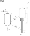
  • FIG. 2 is a schematic view illustrating an example of the fluid catalytic cracking unit used for the method for producing a hydrocarbon according to the present embodiment.
  • a fluid catalytic cracking unit A includes: a reactor 1; a regenerator 3; a line 15 connecting to the reactor 1; a line 11 connecting the reactor 1 and the regenerator 3; a line 23 connecting the reactor 1 and the regenerator 3; a line 27 connecting the regenerator 3 and a boiler (not shown in the drawing); and a line 29 connecting the reactor 1 and a recovery unit (not shown in the drawing).
  • the reactor 1 is a riser type.
  • the reactor 1 includes a reaction zone 5 and a separation zone 7.
  • the reactor 1 is fed with a feedstock and innumerable catalyst particles (cracking catalyst).
  • the feedstock is fed into the reaction zone 5 through the line 15.
  • the feedstock may be obtained by mixing the FT synthetic oil and the hydrocarbon oil in the line 15.
  • the line 15 may branch off from the middle.
  • the feedstock further includes a hydrocarbon oil having a higher %C A than the FT synthetic oil
  • a mixture obtained by mixing the FT synthetic oil and the hydrocarbon oil in advance may be fed as the feedstock to the reaction zone 5 through the line 15.
  • the catalyst particles are fed into the reaction zone 5 through the line 11.
  • a fluidizing gas 13 which is steam, is blown from the lower part of a layer formed of the catalyst particles.
  • the catalyst particles are fluidized by the fluidizing gas 13.
  • the feedstock and the fluidized catalyst particles move up through the reaction zone 5 together with the fluidizing gas 13.
  • catalytic cracking occurs, and hydrocarbons are produced from the feedstock.
  • the hydrocarbons obtained by cracking the feedstock and the catalyst particles used for catalytic cracking are separated in the separation zone 7.
  • the separated hydrocarbons are fed into the recovery unit through the line 29.
  • the hydrocarbons are separated into a plurality of components and recovered in the recovery unit.
  • the recovery unit may include, for example, a plurality of distillation columns, absorbers, compressors, strippers, fractionators, splitters, and heat exchangers.
  • the hydrocarbons are fractionated into, for example, gas components and hydrocarbon oil in the distillation column (atmospheric distillation column).
  • the gas components include dry gas and LP gas (LPG).
  • Examples of the hydrocarbon oil include a gasoline fraction (CCG), a gas oil fraction (LCO), a kerosene fraction, clarified oil (CLO), and coke.
  • the recovered clarified oil (CLO) may be fed into the reactor 1 as a feedstock.
  • the separated catalyst particles are fed into the regenerator 3 through the line 23. Coke generated during fluid catalytic cracking is attached to the surface of the catalyst particles fed into the regenerator 3, and the catalyst particles have deteriorated catalytic activity. In the regenerator 3, the catalyst particles used for catalytic cracking are regenerated. Air 25 is supplied to the regenerator 3 for the regeneration treatment. In the regenerator 3, by combusting the coke attached to the surface of the catalyst particles, the amount of coke attached to the surface of the catalyst particles is reduced, and at the same time, the temperature of the catalyst particles is increased. The catalyst particles after regeneration are fed into the reaction zone 5 again through the line 11. That is, the catalyst particles circulate between the regenerator 3 and the reactor 1.
  • High-temperature carbon monoxide gas and carbon dioxide gas generated in the course of the regeneration treatment are supplied to a boiler (not shown in the drawing) or a heat exchanger (not shown in the drawing) through the line 27 and serves as one of heat sources for the fluid catalytic cracking unit A.
  • the gases are utilized for increasing the temperature of the feedstock.
  • a value obtained by dividing the circulation rate (ton/h) of the catalyst circulating between the reactor 1 and the regenerator 3 by the feed rate (ton/h) of the feedstock is a catalyst/oil ratio.
  • the catalyst/oil ratio is 3 [mass/mass] or more and may be 4 [mass/mass] or more, may be 5 [mass/mass] or more, or may be 7.5 [mass/mass] or more.
  • the catalyst/oil ratio is 50 [mass/mass] or less and may be 13 [mass/mass] or less, may be 12 [mass/mass] or less, 11 [mass/mass] or less, or may be 9 [mass/mass] or less.
  • the cracking catalyst used for fluid catalytic cracking may include, for example, an inorganic oxide (matrix component) and zeolite.
  • the inorganic oxide may be, for example, at least one selected from the group consisting of kaolin, montmorinite, halloysite, bentonite, alumina, silica, boria, chromia, magnesia, zirconia, titania, and silica-alumina.
  • the zeolite may be, for example, at least any of natural zeolite and synthetic zeolite.
  • the natural zeolite may be at least one selected from the group consisting of gmelinite, chabazite, dachiardite, clinoptilolite, faujasite, keyite, heulandite, levynite, erionite, sodalite, cancrinite, ferrierite, brewsterite, offretite, natrolite, and mordenite.
  • the synthetic zeolite may be at least one selected from the group consisting of X-type zeolite, Y-type zeolite, USY-type zeolite, A-type zeolite, L-type zeolite, ZK-4-type zeolite, B-type zeolite, E-type zeolite, F-type zeolite, H-type zeolite, J-type zeolite, M-type zeolite, Q-type zeolite, T-type zeolite, W-type zeolite, Z-type zeolite, ⁇ -type zeolite, ⁇ -type zeolite, ⁇ -type zeolite, ZSM-5-type zeolite, SAPO-5-type zeolite, SAPO-11-type zeolite, and SAPO-34-type zeolite.
  • the reaction temperature for the fluid catalytic cracking of the feedstock may be 500 to 700°C.
  • the reaction temperature is 500°C or higher, there is a tendency that the cracking ratio is likely to be improved, and the yield of the gasoline fraction is likely to be improved.
  • the reaction temperature is 700°C or lower, there is a tendency that excessive cracking reaction can be suppressed, and the yield of the gasoline fraction is likely to be improved.
  • the reaction time (contact time) of fluid catalytic cracking may be 0.5 to 10 seconds. In a case where the reaction time of fluid catalytic cracking is 0.5 seconds or more, there is a tendency that the cracking ratio is likely to be improved, and the yield of the gasoline fraction is likely to be improved. In a case where the reaction time (contact time) of fluid catalytic cracking is 10 seconds or less, there is a tendency that excessive cracking reaction can be suppressed, and the yield of the gasoline fraction is likely to be improved.
  • the mass of steam supplied to the fluid catalytic cracking unit A as a fluidizing gas 13 may be 2 to 50 parts by mass with respect to 100 parts by mass of the feedstock.
  • the mass of steam is 2 parts by mass or more, the feedstock is sufficiently dispersed, and coking tends to be suppressed.
  • the contact time can be prevented from becoming too short, and there is a tendency that the yield of the gasoline fraction is likely to be improved.
  • the pressure inside the reactor 1 where fluid catalytic cracking is performed may be 101325 to 3 ⁇ 10 5 Pa.
  • the pressure is 101325 Pa (standard pressure) or higher, the pressure of gases after cracking does not drop too much, and operation of the recovery unit tends to be stabilized.
  • the pressure is 3 ⁇ 10 5 Pa or lower, the hydrocarbon partial pressure in the reactor 1 can be prevented from becoming too high, and the cracking ratio can be prevented from becoming too high. Therefore, excessive cracking reaction can be suppressed, and there is a tendency that the yield of the gasoline fraction is likely to be improved.
  • the 1-volume% distillation temperature (T1), the 5-volume% distillation temperature (T5), the 10-volume% distillation temperature (T10), the 30-volume% distillation temperature (T30), the 50-volume% distillation temperature (T50), the 70-volume% distillation temperature (T70), the 90-volume% distillation temperature (T90), the 95-volume% distillation temperature (T95), and the 99-volume% distillation temperature (T99) are shown in Table 2.
  • the carbon residue content of the material of a feedstock is a value measured by the method of JIS K 2270-2.
  • the sulfur content of the material of the feedstock is a value measured by the method of JIS K 2541-4.
  • the distillation characteristics of the material of the feedstock are values measured by ASTM D2887.
  • the aromatic content, the naphthene content, and the paraffin content of the material of the feedstock are values measured by an n-d-m method.
  • y is calculated by substituting the measured values of the specific gravity and the refractive index of the feedstock at 70°C into the following Formula (B1).
  • %C R is calculated by substituting y into the following Formula (B2) in a case where y is more than 0, and into the following Formula (B3) in a case where y is less than 0.
  • %Cp is calculated by substituting the %C R into the following Formula (B4).
  • %C N is calculated by substituting the %C R and the %C A for the material of the feedstock measured by an n-d-m method (ASTM D3228-equivalent method) into the following Formula (B5).
  • the following Formulas (B1) to (B5) are defined with reference to the standard "ASTM D3238".
  • M represents the average molecular weight.
  • ROT Riviere Outlet Temperature
  • ROT is the temperature of hydrocarbons at the outlet of the reactor 1, through which the hydrocarbons heading from the reactor 1 to the recovery unit pass.
  • reactor A: fluid catalytic cracking unit.

Landscapes

  • Chemical & Material Sciences (AREA)
  • Oil, Petroleum & Natural Gas (AREA)
  • Engineering & Computer Science (AREA)
  • Chemical Kinetics & Catalysis (AREA)
  • General Chemical & Material Sciences (AREA)
  • Organic Chemistry (AREA)
  • Production Of Liquid Hydrocarbon Mixture For Refining Petroleum (AREA)

Abstract

A method for producing a hydrocarbon according to the present disclosure includes a step of treating a feedstock using a fluid catalytic cracking unit, the feedstock includes FT synthetic oil, and the feedstock has a %CA of 6 to 23.

Description

    Technical Field
  • The present disclosure relates to a method for producing a hydrocarbon.
  • Background Art
  • In domestic refineries in Japan, fluid catalytic cracking (FCC) units play a central role in the production of hydrocarbons (for example, Patent Literature 1).
  • FIG. 1 is a flow chart illustrating an example of a conventional method for producing hydrocarbons from crude oil. In the conventional method for producing hydrocarbons, as shown in FIG. 1, for example, hydrocarbons are produced by using a desulfurized atmospheric residue and a desulfurized vacuum gas oil, which are obtained by treating an atmospheric residue in a residue desulfurization unit, as feedstocks and treating the feedstocks in a fluid catalytic cracking unit.
  • Furthermore, as environmental awareness is increasing, attention has been paid to FT synthetic oil having lower sulfur content and nitrogen content as compared with petroleum. FT synthetic oil is produced by Fischer-Tropsch synthesis from synthesis gas, which is a gas mixture of hydrogen gas and carbon monoxide gas. For example, Patent Literature 2 discloses a technology for producing hydrocarbons by treating the FT synthetic oil as a feedstock in a fluid catalytic cracking unit.
  • Citation List Patent Literature
    • Patent Literature 1: Japanese Unexamined Patent Publication No. 2020-186384
    • Patent Literature 2: Japanese Unexamined Patent Publication No. 2007-503503
    Summary of Invention Technical Problem
  • Coke produced from a feedstock in the course of fluid catalytic cracking adheres to the surface of catalysts. The fluid catalytic cracking unit regenerates catalysts and also utilizes the coke as its own heat source by sending coke-attached catalysts to a regenerator and combusting coke within the regenerator.
  • However, as a result of studies conducted by the inventors of the present invention, it was found that when FT synthetic oil is treated in a fluid catalytic cracking unit, the amount of coke produced during fluid catalytic cracking is small, and there is a possibility that the heat source of the fluid catalytic cracking unit may be insufficient as compared to the case of treating oil derived from petroleum. That is, it is difficult to maintain the heat balance of the fluid catalytic cracking unit, and there is room for improvement from the viewpoint of stable operation of the fluid catalytic cracking unit. When a fluid catalytic cracking unit cannot operate stably, the utilization rate of the fluid catalytic cracking unit decreases, which leads to an increase in the production cost for hydrocarbons.
  • Thus, an aspect of the present disclosure provides a method for producing a hydrocarbon, which method uses FT synthetic oil as a feedstock and allows stable operation.
  • Solution to Problem
  • An aspect of the present disclosure relates to a method for producing a hydrocarbon, the method including a step of treating a feedstock using a fluid catalytic cracking unit, in which the feedstock includes FT synthetic oil, and the feedstock has a %CA of 6 to 23.
  • According to an embodiment, the above-described method for producing a hydrocarbon may further include: a step of mixing the FT synthetic oil and a hydrocarbon oil having a higher %CA than the FT synthetic oil to obtain the feedstock; and a step of feeding the feedstock into a reactor of the fluid catalytic cracking unit. According to an embodiment, the hydrocarbon oil may include a desulfurized atmospheric residue. According to an embodiment, the hydrocarbon oil may include clarified oil.
  • Advantageous Effects of Invention
  • According to an aspect of the present disclosure, there is provided a method for producing a hydrocarbon, which method uses FT synthetic oil as a feedstock and enables stable operation.
  • Brief Description of Drawings
    • [FIG. 1] FIG. 1 is a flowchart illustrating an example of a conventional method for producing a hydrocarbon from crude oil.
    • [FIG. 2] FIG. 2 is a schematic view illustrating an example of a fluid catalytic cracking unit used for a method for producing a hydrocarbon according to an embodiment.
    Description of Embodiments
  • Embodiments of the present disclosure will be described below with reference to the drawings. However, the present disclosure is not limited to the following embodiments and is indicated by the scope of claims, and it is intended that all changes in the meaning and the scope equivalent to the scope of claims are included. In each of the drawings, a portion of the configuration may be shown in an exaggerated or simplified manner for the convenience of explanation. In addition, the dimensional ratio of each part may be different in each of the drawings. In the following description of the drawings, the same or similar parts may be assigned with the same or similar reference numerals.
  • In the present specification, a synthetic oil produced by Fischer-Tropsch synthesis is referred to as "FT synthetic oil". In the present specification, a wax component included in the FT synthetic oil is referred to as "FT wax". In the present specification, an FT synthetic oil produced by Fischer-Tropsch synthesis and not subjected to distillation is referred to as "FT crude oil". In the present specification, with regard to "ton", not the yard-pound system but the metric system is adopted. That is, 1 ton is 1000 kg.
  • In the present specification, the term %CA means an n-d-m method value (aromatic content). Specifically, %CA is calculated by the following procedure. That is, the specific gravity (d470) and the refractive index (nd 70) of the feedstock at 70°C are measured. x is calculated by substituting the measured values into the following Formula (A1). With regard to the calculated x, a value determined by substituting x into the following Formula (A2) in a case where x is more than 0, and into the following Formula (A3) in a case where x is less than 0, is the %CA of the feedstock. The following Formulas (A1) to (A3) are defined with reference to the standard "ASTM D3238". In Formulas (A2) and (A3), M represents the average molecular weight. x = 2.42 n d 70 1.4600 d 4 70 0.8280
    Figure imgb0001
    % C A = 410 x + 3660 / M
    Figure imgb0002
    % C A = 720 x + 3660 / M
    Figure imgb0003
  • A method for producing a hydrocarbon according to an embodiment will be described below. The method for producing a hydrocarbon of the present embodiment includes a step of treating a feedstock using a fluid catalytic cracking unit. The feedstock includes FT synthetic oil, and the feedstock has a %CA of 6 to 23.
  • <Method for producing FT synthetic oil>
  • First, an outline of a method for producing FT synthetic oil that is used in the method for producing a hydrocarbon according to the present embodiment will be described. FT synthetic oil is produced by Fischer-Tropsch synthesis, for example, using carbon monoxide and hydrogen gas as feedstocks. The method for producing the FT synthetic oil is not particularly limited, and a known method can be employed. The reaction unit for producing the FT synthetic oil is preferably a fixed bed reaction unit or a slurry fluidized bed reaction unit. In addition, it is preferable to perform the reaction under the conditions in which the conversion rate of carbon monoxide, which is a feedstock, is set to be 50% or more, and even more preferably in the range of 70 to 90%.
  • As the slurry fluidized bed reaction unit, for example, a bubbling column type fluidized bed reaction unit can be used. A bubbling column type fluidized bed reaction unit has a reactor that performs Fischer-Tropsch synthesis. Inside the reactor of the bubbling column type fluidized bed reaction unit, liquid hydrocarbons that are liquid at the reaction temperature are accommodated. A catalyst for FT synthesis is dispersed in the liquid hydrocarbons, and the liquid hydrocarbons are in a slurry state. Synthesis gas, which is a gas mixture of carbon monoxide gas and hydrogen gas, is introduced into the liquid hydrocarbons from the lower part of the reactor. The synthesis gas dissolves in the liquid hydrocarbons while rising in the liquid hydrocarbons after becoming bubbles, and comes into contact with the catalyst for FT synthesis. The FT synthetic oil is produced from the synthesis gas by the function of the catalyst for FT synthesis.
  • The reaction temperature can be determined depending on the target carbon monoxide conversion rate; however, the reaction temperature is preferably 150 to 300°C, and more preferably 170 to 250°C.
  • The reaction pressure is preferably 0.5 to 5.0 MPa, and more preferably 2.0 to 4.0 MPa. When the reaction pressure is 0.5 MPa or more, there is a tendency that the carbon monoxide conversion rate is likely to be 50% or higher, and when the reaction pressure is 5.0 MPa or less, there is a tendency that the occurrence of local heat generation can be suppressed.
  • Synthesis gas is obtained by, for example, reforming of hydrocarbons such as natural gas. Synthesis gas only needs to include carbon monoxide gas and hydrogen gas and may be a gas other than a gas obtained by reforming of natural gas or the like.
  • The hydrogen/carbon monoxide ratio (molar ratio) in the synthesis gas is preferably 0.5 to 4.0, and more preferably 1.0 to 2.5. When this molar ratio is 0.5 or higher, the reaction temperature does not increase too high while deactivation of the catalyst tends to be suppressed, and when the molar ratio is 4.0 or lower, there is a tendency that production of methane, which is an undesirable byproduct, can be suppressed.
  • The gas space velocity of the synthesis gas is preferably 500 to 5000 h-1, and more preferably 1000 to 2500 h-1. When this gas space velocity is 500 h-1 or more, higher productivity is obtained with the same amount of catalyst, and when the gas space velocity is 5000 h-1 or less, there is a tendency that the conversion rate of carbon monoxide is likely to be 50% or higher.
  • As the catalyst for FT synthesis, a catalyst in which an active metal is supported on an inorganic carrier is used. Examples of the inorganic carrier include porous oxides such as silica, alumina, titania, magnesia, and zirconia. Examples of the active metal include cobalt, ruthenium, iron, and nickel. Furthermore, in the catalyst, a compound including a metal element such as zirconium, titanium, hafnium, sodium, lithium, or magnesium may also be supported, in addition to the above-described active metals. These components improve the catalytic activity and contribute to the control of the number of carbon atoms and the distribution thereof in the FT synthetic oil.
  • The FT synthetic oil is, for example, a mixture of straight-chained hydrocarbons (normal paraffins) having 5 to 100 carbon atoms. The FT synthetic oil may be a synthetic oil produced by Fischer-Tropsch synthesis and may include straight-chained hydrocarbons having more than 100 carbon atoms. The FT synthetic oil includes almost none of aromatic hydrocarbons, naphthene, and isoparaffin. The FT synthetic oil has, for example, a %CA of 0. Incidentally, the FT synthetic oil may have a %CA of more than 0, for example, in a case where aromatic hydrocarbons are included.
  • The FT synthetic oil may include an FT wax having a boiling point of higher than 330°C. The FT wax is, for example, a mixture of straight-chained hydrocarbons (normal paraffins) having 17 or more carbon atoms. The percentage content of the FT wax in the FT synthetic oil may be 30% by mass or more, 50% by mass or more, 70% by mass or more, 90% by mass or more, or 95% by mass or more and may be 100% by mass. The percentage content of the FT wax in the FT synthetic oil can be easily controlled by appropriately adjusting the above-described reaction conditions.
  • <Method for producing hydrocarbon>
  • Next, an outline of the method for producing a hydrocarbon according to the present embodiment will be described. Hydrocarbons can be produced by treating a feedstock including FT synthetic oil in a fluid catalytic cracking unit.
  • The %CA of the feedstock is 6 or more, and from the viewpoint of the amount of coke production, the %CA is preferably 7 or more, and more preferably 8 or more. The %CA of the feedstock is 23 or less and may be 22 or less, or may be 21 or less.
  • The FT synthetic oil included in the feedstock may be an oil produced by Fischer-Tropsch synthesis and is not particularly limited. The FT synthetic oil included in the feedstock may be, for example, an FT crude oil, may be an oil obtained by distilling FT crude oil, may be an FT wax, or may be a mixture of these.
  • The feedstock may further include a hydrocarbon oil having a higher %CA than the FT synthetic oil.
  • The above-described hydrocarbon oil is obtained from, for example, refining. Examples of the above-described hydrocarbon oil include RDS-BTM, DS-VGO, and CLO. As shown in FIG. 1, RDS-BTM is a desulfurized atmospheric residue obtained by treating an atmospheric residue in a residue desulfurization unit. The atmospheric residue is obtained by treating crude oil in an atmospheric distillation unit. As shown in FIG. 1, DS-VGO is, for example, a desulfurized vacuum gas oil obtained by treating an atmospheric residue in a vacuum gas oil desulfurization unit. RDS-BTM may or may not include a solvent deasphalted vacuum residual oil as a feedstock thereof. As shown in FIG. 1, CLO (CLarified Oil) is, for example, a product obtained by removing catalyst from a slurry oil, which is a residual oil obtained by treating RDS-BTM or DS-VGO in a fluid catalytic cracking unit to obtain an oil and further treating the obtained oil in an atmospheric distillation unit. CLO may or may not include FT synthetic oil as a feedstock thereof.
  • In a case where the feedstock includes the above-described hydrocarbon oil, the method for producing a hydrocarbon according to the present embodiment may further include: a step of mixing FT synthetic oil and a hydrocarbon oil to obtain a feedstock; and a step of feeding the feedstock into the reactor of the fluid catalytic cracking unit. As a result, the oil constituting the feedstock becomes more uniform as compared to the case where the feedstock is obtained in the reactor of the fluid catalytic cracking unit. Therefore, the fluid catalytic cracking reaction in the reactor tends to be more stable.
  • In a case where the feedstock includes the above-described hydrocarbon oil, the method for producing a hydrocarbon according to the present embodiment may further include a step of feeding FT synthetic oil into the reactor of the fluid catalytic cracking unit while at the same time, feeding a hydrocarbon oil into the reactor of the fluid catalytic cracking unit, and obtaining a feedstock in the reactor of the fluid catalytic cracking unit.
  • In a case where the feedstock includes RDS-BTM, the proportion occupied by RDS-BTM in RDS-BTM and FT synthetic oil is 1% by mass or more based on the total mass of RDS-BTM and FT synthetic oil, and the proportion may be 15% by mass or more, may be 30% by mass or more, or may be 45% by mass or more.
  • The proportion occupied by RDS-BTM in RDS-BTM and FT synthetic oil is 98% by mass or less based on the total mass of RDS-BTM and FT synthetic oil, and the proportion may be 75% by mass or less, or may be 50% by mass or less.
  • The %CA of RDS-BTM is 5 or more and may be 10 or more, or may be 20 or more. The %CA of RDS-BTM is 99 or less and may be 80 or less, or may be 60 or less.
  • In a case where the feedstock includes DS-VGO, the proportion occupied by DS-VGO in DS-VGO and FT synthetic oil is 1% by mass or more based on the total mass of DS-VGO and FT synthetic oil, and the proportion may be 15% by mass or more, may be 30% by mass or more, or may be 45% by mass or more.
  • The proportion occupied by DS-VGO in DS-VGO and FT synthetic oil is 98% by mass or less based on the total mass of DS-VGO and FT synthetic oil, and the proportion may be 75% by mass or less or may be 50% by mass or less.
  • The %CA of DS-VGO is, for example, 1 or more and may be 5 or more, or may be 10 or more. The %CA of DS-VGO is 99 or less and may be 80 or less, or may be 60 or less.
  • In a case where the feedstock includes CLO, the proportion occupied by CLO in CLO and FT synthetic oil is 1% by mass or more based on the total mass of CLO and FT synthetic oil, and the proportion may be 15% by mass or more, may be 30% by mass or more, or may be 45% by mass or more.
  • The proportion occupied by CLO in CLO and FT synthetic oil is 98% by mass or less based on the total mass of CLO and FT synthetic oil, and the proportion may be 75% by mass or less or may be 50% by mass or less.
  • The %CA of CLO is, for example, 1 or more and may be 5 or more, may be 10 or more, or may be 20 or more. The %CA of CLO is 99 or less and may be 80 or less, or may be 60 or less.
  • RDS-BTM, DS-VGO, and CLO may be used in combination of two or more kinds such that the %CA of the feedstock is within the range of the above-mentioned upper limit value and lower limit value.
  • The fluid catalytic cracking unit used for fluid catalytic cracking of the feedstock is not particularly limited. Regarding the fluid catalytic cracking unit, a known fluid catalytic cracking unit can be used. FIG. 2 is a schematic view illustrating an example of the fluid catalytic cracking unit used for the method for producing a hydrocarbon according to the present embodiment. A fluid catalytic cracking unit A includes: a reactor 1; a regenerator 3; a line 15 connecting to the reactor 1; a line 11 connecting the reactor 1 and the regenerator 3; a line 23 connecting the reactor 1 and the regenerator 3; a line 27 connecting the regenerator 3 and a boiler (not shown in the drawing); and a line 29 connecting the reactor 1 and a recovery unit (not shown in the drawing).
  • The reactor 1 is a riser type. The reactor 1 includes a reaction zone 5 and a separation zone 7. The reactor 1 is fed with a feedstock and innumerable catalyst particles (cracking catalyst). The feedstock is fed into the reaction zone 5 through the line 15. In a case where the feedstock further includes a hydrocarbon oil having a higher %CA than the FT synthetic oil, the feedstock may be obtained by mixing the FT synthetic oil and the hydrocarbon oil in the line 15. In this case, the line 15 may branch off from the middle. By feeding the FT synthetic oil through one branched line of the line 15 and feeding the hydrocarbon oil through the other line, the FT synthetic oil and the hydrocarbon oil are mixed at the confluence of the branched lines, and the feedstock is obtained. Furthermore, in a case where the feedstock further includes a hydrocarbon oil having a higher %CA than the FT synthetic oil, a mixture obtained by mixing the FT synthetic oil and the hydrocarbon oil in advance may be fed as the feedstock to the reaction zone 5 through the line 15.
  • The catalyst particles are fed into the reaction zone 5 through the line 11. In the reaction zone 5, a fluidizing gas 13, which is steam, is blown from the lower part of a layer formed of the catalyst particles. The catalyst particles are fluidized by the fluidizing gas 13. The feedstock and the fluidized catalyst particles move up through the reaction zone 5 together with the fluidizing gas 13. When the feedstock comes into contact with the catalyst particles in the reaction zone 5, catalytic cracking occurs, and hydrocarbons are produced from the feedstock. The hydrocarbons obtained by cracking the feedstock and the catalyst particles used for catalytic cracking are separated in the separation zone 7.
  • The separated hydrocarbons are fed into the recovery unit through the line 29. The hydrocarbons are separated into a plurality of components and recovered in the recovery unit. The recovery unit may include, for example, a plurality of distillation columns, absorbers, compressors, strippers, fractionators, splitters, and heat exchangers. The hydrocarbons are fractionated into, for example, gas components and hydrocarbon oil in the distillation column (atmospheric distillation column). The gas components include dry gas and LP gas (LPG). Examples of the hydrocarbon oil include a gasoline fraction (CCG), a gas oil fraction (LCO), a kerosene fraction, clarified oil (CLO), and coke. The recovered clarified oil (CLO) may be fed into the reactor 1 as a feedstock.
  • The separated catalyst particles are fed into the regenerator 3 through the line 23. Coke generated during fluid catalytic cracking is attached to the surface of the catalyst particles fed into the regenerator 3, and the catalyst particles have deteriorated catalytic activity. In the regenerator 3, the catalyst particles used for catalytic cracking are regenerated. Air 25 is supplied to the regenerator 3 for the regeneration treatment. In the regenerator 3, by combusting the coke attached to the surface of the catalyst particles, the amount of coke attached to the surface of the catalyst particles is reduced, and at the same time, the temperature of the catalyst particles is increased. The catalyst particles after regeneration are fed into the reaction zone 5 again through the line 11. That is, the catalyst particles circulate between the regenerator 3 and the reactor 1. High-temperature carbon monoxide gas and carbon dioxide gas generated in the course of the regeneration treatment are supplied to a boiler (not shown in the drawing) or a heat exchanger (not shown in the drawing) through the line 27 and serves as one of heat sources for the fluid catalytic cracking unit A. In a case where the carbon monoxide gas and carbon dioxide gas generated in the course of the regeneration treatment are supplied to a heat exchanger, the gases are utilized for increasing the temperature of the feedstock.
  • A value obtained by dividing the circulation rate (ton/h) of the catalyst circulating between the reactor 1 and the regenerator 3 by the feed rate (ton/h) of the feedstock is a catalyst/oil ratio. The catalyst/oil ratio is 3 [mass/mass] or more and may be 4 [mass/mass] or more, may be 5 [mass/mass] or more, or may be 7.5 [mass/mass] or more. The catalyst/oil ratio is 50 [mass/mass] or less and may be 13 [mass/mass] or less, may be 12 [mass/mass] or less, 11 [mass/mass] or less, or may be 9 [mass/mass] or less.
  • The cracking catalyst used for fluid catalytic cracking may include, for example, an inorganic oxide (matrix component) and zeolite. The inorganic oxide may be, for example, at least one selected from the group consisting of kaolin, montmorinite, halloysite, bentonite, alumina, silica, boria, chromia, magnesia, zirconia, titania, and silica-alumina. The zeolite may be, for example, at least any of natural zeolite and synthetic zeolite. The natural zeolite may be at least one selected from the group consisting of gmelinite, chabazite, dachiardite, clinoptilolite, faujasite, keyite, heulandite, levynite, erionite, sodalite, cancrinite, ferrierite, brewsterite, offretite, natrolite, and mordenite. The synthetic zeolite may be at least one selected from the group consisting of X-type zeolite, Y-type zeolite, USY-type zeolite, A-type zeolite, L-type zeolite, ZK-4-type zeolite, B-type zeolite, E-type zeolite, F-type zeolite, H-type zeolite, J-type zeolite, M-type zeolite, Q-type zeolite, T-type zeolite, W-type zeolite, Z-type zeolite, α-type zeolite, β-type zeolite, ω-type zeolite, ZSM-5-type zeolite, SAPO-5-type zeolite, SAPO-11-type zeolite, and SAPO-34-type zeolite.
  • The reaction temperature for the fluid catalytic cracking of the feedstock may be 500 to 700°C. In a case where the reaction temperature is 500°C or higher, there is a tendency that the cracking ratio is likely to be improved, and the yield of the gasoline fraction is likely to be improved. In a case where the reaction temperature is 700°C or lower, there is a tendency that excessive cracking reaction can be suppressed, and the yield of the gasoline fraction is likely to be improved.
  • The reaction time (contact time) of fluid catalytic cracking may be 0.5 to 10 seconds. In a case where the reaction time of fluid catalytic cracking is 0.5 seconds or more, there is a tendency that the cracking ratio is likely to be improved, and the yield of the gasoline fraction is likely to be improved. In a case where the reaction time (contact time) of fluid catalytic cracking is 10 seconds or less, there is a tendency that excessive cracking reaction can be suppressed, and the yield of the gasoline fraction is likely to be improved.
  • The mass of steam supplied to the fluid catalytic cracking unit A as a fluidizing gas 13 may be 2 to 50 parts by mass with respect to 100 parts by mass of the feedstock. In a case where the mass of steam is 2 parts by mass or more, the feedstock is sufficiently dispersed, and coking tends to be suppressed. In a case where the mass of steam is 50 parts by mass or less, the contact time can be prevented from becoming too short, and there is a tendency that the yield of the gasoline fraction is likely to be improved.
  • The pressure inside the reactor 1 where fluid catalytic cracking is performed may be 101325 to 3×10⁵ Pa. In a case where the pressure is 101325 Pa (standard pressure) or higher, the pressure of gases after cracking does not drop too much, and operation of the recovery unit tends to be stabilized. In a case where the pressure is 3×10⁵ Pa or lower, the hydrocarbon partial pressure in the reactor 1 can be prevented from becoming too high, and the cracking ratio can be prevented from becoming too high. Therefore, excessive cracking reaction can be suppressed, and there is a tendency that the yield of the gasoline fraction is likely to be improved.
  • Examples
  • Hereinafter, the present disclosure will be described in more detail by way of Examples; however, the present disclosure is not intended to be limited to these Examples.
  • <Simulation of hydrocarbon production> (Examples 1 to 9 and Comparative Example 1)
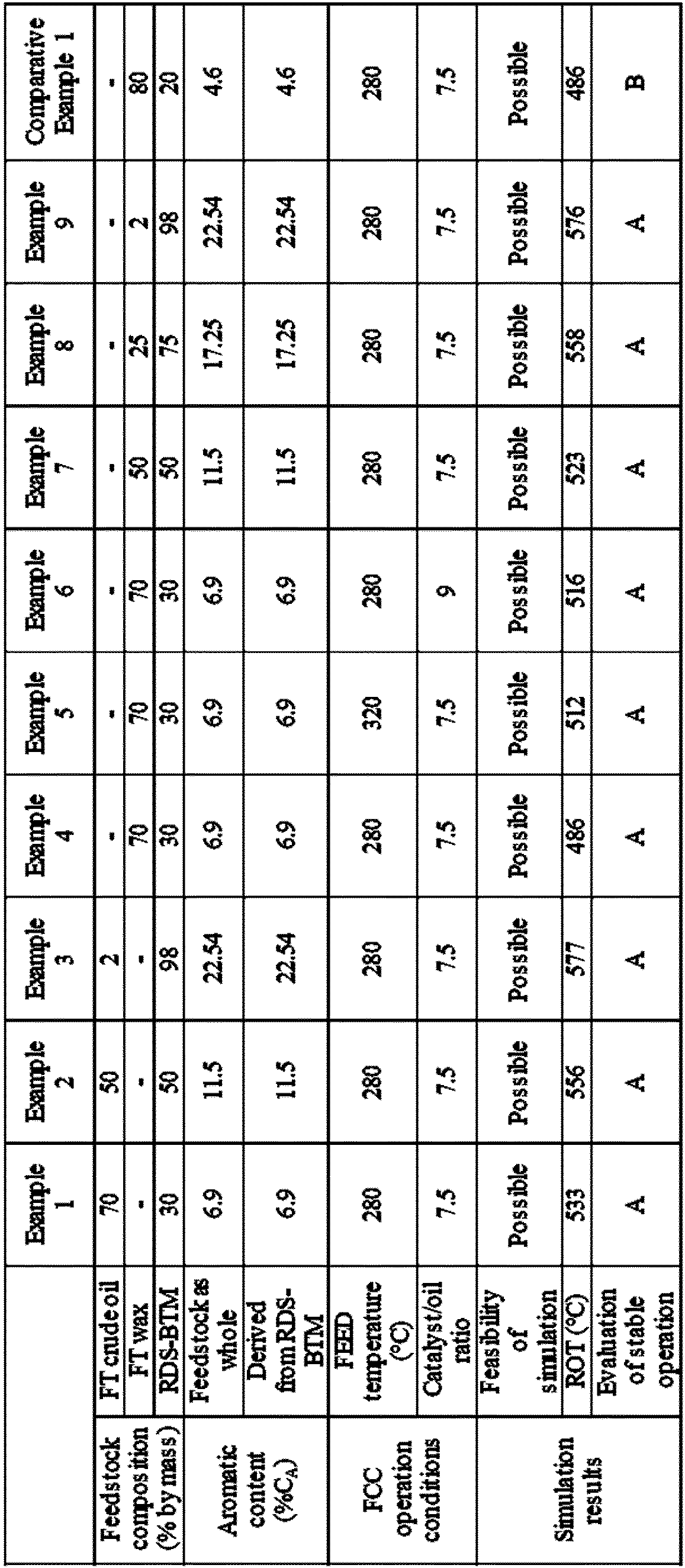
  • Whether stable operation of hydrocarbon production by the fluid catalytic cracking unit A is possible was verified by simulation. Specifically, simulation of feeding a feedstock into the reactor 1 and subjecting the feedstock to fluid catalytic cracking to produce hydrocarbons was performed. The simulation was performed using "FCC-SIM ver 6.2" (trade name) manufactured by KBC Corporation. The catalyst/oil ratio and the temperature at which a feedstock was fed into the reactor 1 (FEED temperature) were set to the values in Table 1.
  • Simulation was performed for feedstocks having the compositions shown in Table 1. The aromatic content in the feedstock is shown in Table 1. The density at 15°C, the sulfur content, the carbon residue content, the distillation characteristics, the aromatic content, the naphthene content, and the paraffin content for the materials of the feedstocks were assumed to have the values shown in Table 2. Regarding the distillation characteristics of the materials of the feedstocks, the 1-volume% distillation temperature (T1), the 5-volume% distillation temperature (T5), the 10-volume% distillation temperature (T10), the 30-volume% distillation temperature (T30), the 50-volume% distillation temperature (T50), the 70-volume% distillation temperature (T70), the 90-volume% distillation temperature (T90), the 95-volume% distillation temperature (T95), and the 99-volume% distillation temperature (T99) are shown in Table 2.
  • The carbon residue content of the material of a feedstock is a value measured by the method of JIS K 2270-2. The sulfur content of the material of the feedstock is a value measured by the method of JIS K 2541-4. The distillation characteristics of the material of the feedstock are values measured by ASTM D2887. The aromatic content, the naphthene content, and the paraffin content of the material of the feedstock are values measured by an n-d-m method.
  • A method for measuring the naphthene content and the paraffin content of the material of the feedstock will be described in detail. First, the specific gravity (d4 70), the refractive index (nd 70), and the sulfur content (SC) of the feedstock at 70°C are measured. y is calculated by substituting the measured values of the specific gravity and the refractive index of the feedstock at 70°C into the following Formula (B1). With regard to the calculated y, %CR is calculated by substituting y into the following Formula (B2) in a case where y is more than 0, and into the following Formula (B3) in a case where y is less than 0. %Cp is calculated by substituting the %CR into the following Formula (B4). %CN is calculated by substituting the %CR and the %CA for the material of the feedstock measured by an n-d-m method (ASTM D3228-equivalent method) into the following Formula (B5). The following Formulas (B1) to (B5) are defined with reference to the standard "ASTM D3238". In Formula (B2) and Formula (B3), M represents the average molecular weight. y = n d 70 0.8280 1.11 × d 4 70 1.460
    Figure imgb0004
    % C R = 775 y 3 × SC + 11500 / M
    Figure imgb0005
    % C R = 1400 y 3 × SC + 12100 / M
    Figure imgb0006
    % C P = 100 % C R
    Figure imgb0007
    % C N = % C R % C A
    Figure imgb0008
  • The feasibility of the simulation is shown in Table 1. The fact that simulation is possible means that ROT is calculated for the set values (a solution is obtained by executing the simulation). The fact that simulation is impossible means that ROT is not calculated for the set values (a solution is not obtained by executing the simulation). ROT (Riser Outlet Temperature) is the temperature of hydrocarbons at the outlet of the reactor 1, through which the hydrocarbons heading from the reactor 1 to the recovery unit pass.
  • <Evaluation of stable operation> (Examples 1 to 9 and Comparative Example 1)
  • The results of the simulation were evaluated on the basis of the following criteria. The results are shown in Table 1. When the ROT is 480°C or higher, it is considered that the unit can be stably operated by suppressing solidification of the produced oil or the catalyst (bogging).
  • (Criteria)
    1. A: The simulation is possible, and the ROT is 480°C or higher.
    2. B: The simulation is impossible, or although the simulation is possible, the ROT is lower than 480°C.
    Figure imgb0009
    Figure imgb0010
    [Table 2]
    RDS-BTM FT crude oil FT wax
    Density at 15°C (g/cm3) 0.8933 0.7365 0.82
    Sulfur content (% by mass) 0.71 0.01 0.01
    Carbon residue content (% by mass) 3.752 0.01 0.01
    Aromatic content (%CA) 23 0 0
    Naphthene content (%CN) 9 0 0
    Paraffin content (%CP) 68 100 100
    Distillation characteristics (°C) T1 325 30 249
    T5 367 - -
    T10 388 60 330
    T30 439 125 391
    T50 496 150 438
    T70 567 250 450
    T90 685 440 -
    T95 738 - -
    T99 - 450 -
  • As shown in Table 1, it was verified that in a case where the feedstock includes FT synthetic oil, and the feedstock has a %CA of 6 to 23, the unit can be stably operated.
  • Reference Signs List
  • 1: reactor, A: fluid catalytic cracking unit.

Claims (4)

  1. A method for producing a hydrocarbon, the method comprising:
    a step of treating a feedstock using a fluid catalytic cracking unit,
    wherein the feedstock includes FT synthetic oil, and
    the feedstock has a %CA of 6 to 23.
  2. The method for producing a hydrocarbon according to claim 1, further comprising:
    a step of mixing the FT synthetic oil and a hydrocarbon oil having a higher %CA than the FT synthetic oil to obtain the feedstock; and
    a step of feeding the feedstock into a reactor of the fluid catalytic cracking unit.
  3. The method for producing a hydrocarbon according to claim 2, wherein the hydrocarbon oil includes a desulfurized atmospheric residue.
  4. The method for producing a hydrocarbon according to claim 2, wherein the hydrocarbon oil includes clarified oil.
EP23815969.3A 2022-05-31 2023-05-26 METHOD FOR THE PRODUCTION OF HYDROGEN Pending EP4474449A4 (en)

Applications Claiming Priority (2)

Application Number Priority Date Filing Date Title
JP2022088984 2022-05-31
PCT/JP2023/019727 WO2023234212A1 (en) 2022-05-31 2023-05-26 Method for producing hydrocarbon

Publications (2)

Publication Number Publication Date
EP4474449A1 true EP4474449A1 (en) 2024-12-11
EP4474449A4 EP4474449A4 (en) 2025-12-24

Family

ID=89024979

Family Applications (1)

Application Number Title Priority Date Filing Date
EP23815969.3A Pending EP4474449A4 (en) 2022-05-31 2023-05-26 METHOD FOR THE PRODUCTION OF HYDROGEN

Country Status (5)

Country Link
US (1) US20250297171A1 (en)
EP (1) EP4474449A4 (en)
JP (1) JPWO2023234212A1 (en)
AU (1) AU2023280603C1 (en)
WO (1) WO2023234212A1 (en)

Family Cites Families (10)

* Cited by examiner, † Cited by third party
Publication number Priority date Publication date Assignee Title
US4684756A (en) * 1986-05-01 1987-08-04 Mobil Oil Corporation Process for upgrading wax from Fischer-Tropsch synthesis
JP2006528992A (en) * 2003-05-27 2006-12-28 シエル・インターナシヨネイル・リサーチ・マーチヤツピイ・ベー・ウイ Production method of gasoline
ATE417911T1 (en) 2003-08-22 2009-01-15 Sasol Tech Pty Ltd METHOD FOR PRODUCING HYDROCARBONS
RU2388791C2 (en) * 2004-05-26 2010-05-10 Шелл Интернэшнл Рисерч Маатсхаппий Б.В. Method of obtaining gas oil through catalytic cracking of fischer-tropsch synthesis product
EP1981953A2 (en) * 2006-02-09 2008-10-22 Shell Internationale Research Maatschappij B.V. Fluid catalytic cracking process
US20090026112A1 (en) * 2006-02-09 2009-01-29 Jan Lodewijk Maria Dierickx Fluid catalytic cracking process
WO2008026635A1 (en) * 2006-08-31 2008-03-06 Nippon Oil Corporation Fluid catalytic cracking method
WO2008026681A1 (en) * 2006-08-31 2008-03-06 Nippon Oil Corporation Fluid catalytic cracking method
EP2638127A1 (en) * 2010-11-12 2013-09-18 Shell Internationale Research Maatschappij B.V. Process for the preparation of a biofuel and/or biochemical
JP7471904B2 (en) 2019-05-08 2024-04-22 出光興産株式会社 Fluid catalytic cracking gasoline manufacturing method

Also Published As

Publication number Publication date
AU2023280603C1 (en) 2026-02-12
JPWO2023234212A1 (en) 2023-12-07
AU2023280603B2 (en) 2025-10-23
AU2023280603A1 (en) 2024-09-19
EP4474449A4 (en) 2025-12-24
US20250297171A1 (en) 2025-09-25
WO2023234212A1 (en) 2023-12-07

Similar Documents

Publication Publication Date Title
US11760945B2 (en) High severity fluidized catalytic cracking systems and processes for producing olefins from petroleum feeds
US4090949A (en) Upgrading of olefinic gasoline with hydrogen contributors
US8293961B2 (en) Catalytic cracking process using fast fluidization for the production of light olefins from hydrocarbon feedstock
CN108350367B (en) Method and system for fluid catalytic cracking
EP0537500A2 (en) A method of treatment of heavy hydrocarbon oil
EP2716739A1 (en) Monocyclic aromatic hydrocarbon production method and monocyclic aromatic hydrocarbon production plant
US4064038A (en) Fluid catalytic cracking process for conversion of residual oils
JP2017502110A (en) Integrated process of solvent degassing and fluid catalytic cracking for the production of light olefins
US4440629A (en) Hydrocarbon hydrocracking process
CA2103230C (en) Fluid catalytic cracking process for producing light olefins
US4997545A (en) Method for selective alteration of fluid catalytic cracker yield structures
EP4474449A1 (en) Method for producing hydrocarbon
EP4474448A1 (en) Method for producing hydrocarbons
US20040140246A1 (en) Process for upgrading fcc product with additional reactor
JP5399705B2 (en) Fluid catalytic cracking method
JP5390857B2 (en) Fluid catalytic cracking method
KR101672789B1 (en) Catalytic conversion method for improving product distribution
US11891356B2 (en) Production of high yields of light olefins from heavy hydrocarbons
RU2812317C1 (en) Method for converting hydrocarbon feeds into lighter olefins
JP2024051525A (en) Feedstock for fluid catalytic cracking and fluid catalytic cracking process
US20250236797A1 (en) Processes for producing petrochemical products that utilize fluid catalytic cracking
US20260078309A1 (en) Self-heat-balanced hsfcc systems and processes for upgrading hydrocarbon feeds
JPH10168463A (en) Fluid catalytic cracking of oil
JP2017186408A (en) Manufacturing method of hydrocarbon oil
Ihediwa Fluid catalytic cracking

Legal Events

Date Code Title Description
STAA Information on the status of an ep patent application or granted ep patent

Free format text: STATUS: THE INTERNATIONAL PUBLICATION HAS BEEN MADE

PUAI Public reference made under article 153(3) epc to a published international application that has entered the european phase

Free format text: ORIGINAL CODE: 0009012

STAA Information on the status of an ep patent application or granted ep patent

Free format text: STATUS: REQUEST FOR EXAMINATION WAS MADE

17P Request for examination filed

Effective date: 20240904

AK Designated contracting states

Kind code of ref document: A1

Designated state(s): AL AT BE BG CH CY CZ DE DK EE ES FI FR GB GR HR HU IE IS IT LI LT LU LV MC ME MK MT NL NO PL PT RO RS SE SI SK SM TR

DAV Request for validation of the european patent (deleted)
DAX Request for extension of the european patent (deleted)
A4 Supplementary search report drawn up and despatched

Effective date: 20251124

RIC1 Information provided on ipc code assigned before grant

Ipc: C10G 11/18 20060101AFI20251118BHEP