EP4474250A1 - Control device for electric power steering device and electric power steering device - Google Patents
Control device for electric power steering device and electric power steering device Download PDFInfo
- Publication number
- EP4474250A1 EP4474250A1 EP24735460.8A EP24735460A EP4474250A1 EP 4474250 A1 EP4474250 A1 EP 4474250A1 EP 24735460 A EP24735460 A EP 24735460A EP 4474250 A1 EP4474250 A1 EP 4474250A1
- Authority
- EP
- European Patent Office
- Prior art keywords
- steering
- torque
- value
- input
- control value
- Prior art date
- Legal status (The legal status is an assumption and is not a legal conclusion. Google has not performed a legal analysis and makes no representation as to the accuracy of the status listed.)
- Granted
Links
Images






Classifications
-
- B—PERFORMING OPERATIONS; TRANSPORTING
- B62—LAND VEHICLES FOR TRAVELLING OTHERWISE THAN ON RAILS
- B62D—MOTOR VEHICLES; TRAILERS
- B62D15/00—Steering not otherwise provided for
- B62D15/02—Steering position indicators ; Steering position determination; Steering aids
- B62D15/025—Active steering aids, e.g. helping the driver by actively influencing the steering system after environment evaluation
Definitions
- the present invention relates to a control device for electric power steering device and an electric power steering device.
- PTL 1 discloses an automatic steering device including a movement trajectory setting means for setting a movement trajectory of a vehicle up to a target position, a steering actuator control means for calculating a first drive instruction value to be input to a steering actuator based on the movement trajectory and a second drive instruction value to be input to the steering actuator based on a steering force applied by a driver to the steering wheel.
- An objective of the present invention is to achieve both the subtle steering feel when a driver steers and good steering angle tracking performance in a mode where the steering assist control and the steering angle control that causes the actual steering angle follow a target steering angle operate simultaneously.
- a control device for an electric power steering device including: a steering torque detection unit configured to detect a steering torque that is input to a steering mechanism; a first steering control value calculation unit configured to calculate a first steering control value based on the steering torque detected by the steering torque detection unit; a second steering control value calculation unit configured to calculate a second steering control value for causing an actual steering angle to follow a target steering angle; a mixing unit configured to calculate a target steering control value by adding the first steering control value and the second steering control value; and a drive unit configured to drive a motor generating a steering force based on the target steering control value.
- the second steering control value calculation unit includes a disturbance compensation torque setting unit configured to set a disturbance compensation torque, and calculates the second steering control value based on an angular deviation of the actual steering angle relative to the target steering angle and the disturbance compensation torque, and the disturbance compensation torque setting unit sets the disturbance compensation torque including a larger friction component when the steering torque is larger than when the steering torque is smaller.
- an electric power steering device including the control device described above, wherein the electric power steering device controls, by the control device, steering force generated by the motor.
- FIG. 1 is a configuration diagram illustrating an overview of an example of the electric power steering device of an embodiment.
- a steering shaft (handle shaft) 2 of a steering wheel (steering handle) 1 is coupled to the steered wheels 8L and 8R via a reduction gear (worm gear) 3 that constitutes a reduction mechanism, universal joints 4a and 4b, a pinion rack mechanism 5, and tie rods 6a and 6b, and further via hub units 7a and 7b.
- a reduction gear worm gear
- the pinion rack mechanism 5 has a pinion 5a connected to a pinion shaft to which the steering force is transmitted from the universal joint 4b, and a rack 5b that meshes with the pinion 5a, thereby converting a rotational motion transmitted to the pinion 5a into a linear motion in the vehicle width direction with the rack 5b.
- the steering shaft 2 is provided with a torque sensor 10 that detects a steering torque Th.
- the steering shaft 2 is also provided with a steering angle sensor 14 that detects the steering angle ⁇ a of the steering mechanism.
- the steering angle sensor 14 may detect the steering angle ⁇ a of the steering wheel 1 and/or the steering shaft 2.
- the steering angle ⁇ a detected by the steering angle sensor 14 may be referred to as the "actual steering angle ⁇ a.”
- a motor 20 that assists the steering force of the steering wheel 1 is connected to the steering shaft 2 via the reduction gear 3.
- a controller 30 that controls the electric power steering (EPS) device is supplied with electric power from a battery 13 and input with an ignition key signal through an ignition (IGN) key 11.
- the means for providing a steering assist force is not limited to a motor, but various types of actuators can be used.
- the controller 30 is an electronic control unit (ECU) that controls the electric current supplied to the motor 20 using a voltage control command value Vref obtained by calculating the current command value of the assist control command based on the steering torque Th detected by the torque sensor 10, the vehicle speed Vh detected by the vehicle speed sensor 12, and the actual steering angle ⁇ a detected by the steering angle sensor 14 and compensating for the current command value.
- ECU electronice control unit
- the steering angle sensor 14 is not essential, and the actual steering angle ⁇ a may be calculated by adding the torsion angle of the torsion bar of the torque sensor 10 to the rotation angle obtained from the rotation angle sensor that detects the rotation angle of the rotation shaft of the motor 20.
- the turning angle of the steered wheels 8L and 8R may be used as the actual steering angle ⁇ a.
- the turning angle may be detected by detecting the displacement of the rack 5b.
- the controller 30 may include a computer that includes, for example, a processor and peripheral components such as a storage device.
- the processor may be, for example, a central processing unit (CPU) or a micro-processing unit (MPU).
- the storage device may include any of semiconductor, magnetic, and optical storage devices.
- the storage device may include a register, a cache memory, and a memory such as read only memory (ROM) and random access memory (RAM) used as a main memory.
- ROM read only memory
- RAM random access memory
- controller 30 The functions of the controller 30 described below are realized, for example, by the processor of the controller 30 executing a computer program stored in the storage device.
- controller 30 may be formed by dedicated hardware to perform each of the information processing described below.
- the controller 30 may include a functional logic circuit that is configured in a general-purpose semiconductor integrated circuit.
- the controller 30 may have a programmable logic device (PLD) such as a fieldprogrammable gate array (FPGA).
- PLD programmable logic device
- FPGA fieldprogrammable gate array
- FIG. 2 is a block diagram illustrating an example of the functional configuration of the controller 30.
- the controller 30 includes a manual assist control unit 40, a steering angle feedback (FB) control unit 41, a disturbance compensation torque setting unit 42, adders 43 and 46, an operation setting unit 44, a multiplier 45, a command value setting unit 47, a current feedback (FB) control unit 48, a pulse width modulation (PWM) control unit 49, an inverter (INV) 50, and a current detection unit 51.
- FB steering angle feedback
- PWM pulse width modulation
- IV inverter
- the manual assist control unit 40 calculates a first manual assist torque Tma1 and a second manual assist torque Tma2 based at least on the steering torque Th and the vehicle speed Vh.
- the second manual assist torque Tma2 includes the entire component of the steering assist torque that assists the steering of the steering mechanism by a driver, and the first manual assist torque Tma1 includes only the static component of the second manual assist torque Tma2.
- the second manual assist torque Tma2 is an example of the "first steering control value" described in the claims.
- the first manual assist torque Tma1 is an example of the static component of the first steering control value. Details of the manual assist control unit 40 are described below.
- the steering angle FB control unit 41 calculates a steering angle FB torque Tsfb to cause the actual steering angle ⁇ a to follow the target steering angle ⁇ t based at least on the steering torque Th, the vehicle speed Vh, the actual steering angle ⁇ a, the steering angular velocity wa that is the time rate of change of the actual steering angle ⁇ a, and the target steering angle ⁇ t.
- the sign of the steering angular velocity wa when the steering mechanism (for example, the steering wheel 1 and the steering shaft 2) rotates clockwise is defined as positive
- the sign of the steering angular velocity wa when the steering mechanism rotates counterclockwise is defined as negative.
- the steering angular velocity ⁇ a may be referred to as the actual steering angular velocity ⁇ a.
- the target steering angle ⁇ t is the target value of the actual steering angle ⁇ a that is automatically set in the automatic steering control by the controller 30.
- the controller 30 may set a target travel trajectory on which the vehicle should travel and set the target steering angle ⁇ t so that the vehicle travels along the target travel trajectory.
- the controller 30 may also set the target steering angle ⁇ t based on the lateral position in a lane and the deviation margin time to the lane boundary line so that the vehicle travels within the same lane.
- the controller 30 may receive the target steering angle ⁇ t from a high-level controller controlling the vehicle via CAN communication or other means. Details of the steering angle FB control unit 41 are described below.
- the disturbance compensation torque setting unit 42 uses a disturbance observer to set a disturbance compensation torque Tob to compensate for disturbances applied to the steering mechanism.
- the disturbance compensation torque setting unit 42 calculates the disturbance compensation torque Tob based at least on the first manual assist torque Tma1, the second manual assist torque Tma2, the steering torque Th, the vehicle speed Vh, the actual steering angular velocity ⁇ a, and the past value (previous value) of the steering angle tracking torque Tsfw obtained by correcting the steering angle FB torque Tsfb by the disturbance compensation torque Tob. Details of the disturbance compensation torque setting unit 42 are described below.
- the operation setting unit 44 sets an operation gain Gop based on a control signal Ss to set whether the automatic steering control is enabled or not.
- the control signal Ss is set based on the switch on/off of the automatic steering control by an occupant or the reliability of the sensor used for automatic steering control (for example, a camera for detecting a lane) with regard to the malfunction.
- the operation gain Gop is set to the value "1" when the automatic steering control is enabled, and is set to the value "0" when the automatic steering control is disabled.
- the adder 43 compensates for disturbances applied to the steering mechanism by adding the disturbance compensation torque Tob to the steering angle FB torque Tsfb.
- the steering angle tracking torque Tsfw is an example of the "second steering control value" as described in the claims.
- the adder 46 calculates a target steering torque (Tma2 + Tsfw) by adding the second manual assist torque Tma2 and the steering angle tracking torque Tsfw.
- the adder 46 is an example of the "mixing unit” as described in the claims, and the target steering torque (Tma2 + Tsfw) is an example of the "target steering control value" as described in the claims.
- the command value setting unit 47 converts the target steering torque (Tma2 + Tsfw) into a current command value Ir0 and sets a target current command value Ir by limiting the upper limit of the current command value Ir0.
- the current FB control unit 48 generates a voltage control command value Vref by feedback control such as proportional-integral (PI) control based on the deviation between the feedbacked current value Im of the motor 20 and the target current command value Ir.
- the current value Im of the motor 20 is detected by the current detection unit 51.
- the voltage control command value Vref is input to the PWM control unit 49, and the inverter 50 is controlled by a PWM signal generated by the PWM control unit 49 to drive the motor 20.
- the inverter 50 is an example of the "drive unit" as described in the claims.
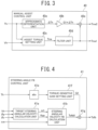
- FIG. 3 is a block diagram illustrating an example of the functional configuration of the manual assist control unit 40.
- the manual assist control unit 40 includes an approximate differentiation unit 40a, a gain multiplication unit 40b, an assist torque setting unit 40c, a filter unit 40d, and an adder 40e.
- the approximate differentiation unit 40a calculates a variation component ⁇ Th of the steering torque Th.
- the approximate differentiation unit 40a may calculate a variation component ⁇ Th by multiplying the transfer function s/(Ts+1) that is a combination of differential operation and low-pass filter by the steering torque Th.
- the approximate differentiation unit 40a simply calculates a variation component ⁇ Th by differentiating the steering torque Th.
- the gain multiplication unit 40b calculates the product, G1 ⁇ ⁇ Th, of the variation component ⁇ Th and a predetermined gain G1.
- the assist torque setting unit 40c sets an assist torque Tma that is a steering assist torque based at least on the steering torque Th and the vehicle speed Vh.
- the assist torque setting unit 40c may set a larger assist torque Tma for a larger steering torque Th.
- the assist torque setting unit 40c may set a larger assist torque Tma for a lower vehicle speed Vh.
- the assist torque setting unit 40c may set an assist torque Tma using an assist map or the like.
- the filter unit 40d calculates a first manual assist torque Tma1 that includes only the static component of the assist torque Tma by removing a resonance component and the like from the assist torque Tma corresponding to the steering torque Th.
- the filter unit 40d may be a notch filter, a low-pass filter, and/or the like.
- the adder 40e calculates a second manual assist torque Tma2 that includes the entire component of the steering assist torque by adding the output of the gain multiplication unit 40b G1 ⁇ ⁇ Th to the first manual assist torque Tma1.
- the second manual assist torque Tma2 includes the static component of the assist torque Tma that is the steering assist torque corresponding to the steering torque Th and the variation component ⁇ Th of the steering torque Th.
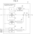
- FIG. 4 is a block diagram illustrating an example of the functional configuration of the steering angle FB control unit 41.
- the steering angle FB control unit 41 includes a target steering angular velocity calculation unit 41a, a steering angular velocity feedback (FB) calculation unit 41b, an absolute value calculation unit (abs) 41e, a torque-sensitive gain setting unit 41f, and a multiplier 41g.
- FB steering angular velocity feedback
- the target steering angular velocity calculation unit 41a calculates a target steering angular velocity wt based on the angular deviation of the actual steering angle ⁇ a relative to the target steering angle ⁇ t and the vehicle speed Vh. For example, the target steering angular velocity calculation unit 41a sets a conversion factor Kpp corresponding to the vehicle speed Vh. For example, the target steering angular velocity calculation unit 41a may set a smaller conversion factor Kpp for a higher vehicle speed Vh.
- the target steering angular velocity calculation unit 41a calculates the product Kpp ⁇ ( ⁇ t - ⁇ a) of the angular deviation ( ⁇ t - ⁇ a) of the actual steering angle ⁇ a relative to the target steering angle ⁇ t and the conversion coefficient Kpp, as the target steering angular velocity wt.
- the steering angular velocity FB calculation unit 41b sets a conversion factor Kpv based on the conversion factor Kpp.
- the conversion factor Kpv may be set to maintain a constant value when the conversion factor Kpp is in the range lower than a threshold value, and to increase as the conversion factor Kpp increases when the conversion factor Kpp is in the range equal to or more than the threshold value.
- the steering angular velocity FB calculation unit 41b calculates the product Kpv ⁇ (wt - wa) of the angular velocity deviation (wt - wa) of the actual steering angular velocity wa relative to the target steering angular velocity wt and the conversion factor Kpv, as the basic steering angle FB torque Tsfb0.
- the absolute value calculation unit 41e outputs the absolute value of the steering torque Th.
- the torque-sensitive gain setting unit 41f sets a torque-sensitive gain G2 according to the output of the absolute value calculation unit 41e. For example, a smaller torque-sensitive gain G2 may be set when the output of the absolute value calculation unit 41e is larger than when the output of the absolute value calculation unit 41e is smaller.
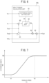
- FIG. 5 is a block diagram illustrating an example of the functional configuration of the disturbance compensation torque setting unit 42.
- the disturbance compensation torque setting unit 42 includes an input torque estimation unit 42a, an input torque calculation unit 42b, filter units 42c and 42e, a friction torque estimation unit 42d, an adder 42f, a subtractor 42g, an absolute value calculation unit (abs) 42j, a torque-sensitive gain setting unit 42k, and a multiplier 42l.
- the input torque estimation unit 42a calculates an estimated input torque Tie that is an estimate value of the input torque to the steering mechanism by inputting the actual steering angular velocity wa to the inverse model of the steering mechanism.
- the input torque estimation unit 42a may calculate an estimated input torque Tie by inputting angle information consisting of the actual steering angle ⁇ a, the actual steering angular velocity ⁇ a, and the actual steering angular acceleration ⁇ a that is the time rate of change of the actual steering angular velocity wa into the inverse model.
- Various equations can be used depending on the combination of input angle information.
- the following equation (2) may be used instead of equation (1).
- the inertia and viscosity terms in equation (1) or equation (2) may be obtained from equation (3) or equation (4).
- Tie J ⁇ s + D ⁇ a ⁇ Q s + K ⁇ ⁇ a ⁇ Q s K is the stiffness and K ⁇ a is the reaction force from the road surface.
- the input torque calculation unit 42b calculates an input torque TiaO that is input to the steering mechanism based at least on the steering torque Th, the vehicle speed Vh, the past value (previous value) of the steering angle tracking torque Tsfw, the first manual assist torque Tma1, and the second manual assist torque Tma2.
- the input torque TiaO calculated by the input torque calculation unit 42b is referred to as the "basic actual input torque TiaO.”
- FIG. 6 is a block diagram illustrating an example of the functional configuration of the input torque calculation unit 42b.
- the input torque calculation unit 42b includes adders 60, 64, and 65, a hysteresis width setting unit 61, a hysteresis processing unit 62, and a subtractor 63.
- the adder 60 calculates the sum (Tma1 + Th) of the first manual assist torque Tma1 and the steering torque Th, as the static manual steering input torque.
- the hysteresis width setting unit 61 sets the hysteresis width Wh of a hysteresis characteristic to be imparted to the static manual steering input torque (Tma1 + Th), the hysteresis width Wh corresponding to the vehicle speed Vh.
- the hysteresis width setting unit 61 may set a wider hysteresis width Wh when the vehicle speed Vh is higher than when the vehicle speed Vh is lower. For example, a wider the hysteresis width Wh may be set for a higher vehicle speed Vh.
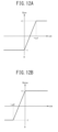
- FIG. 7 is a schematic diagram of an example of the characteristic of the hysteresis width Wh set by the hysteresis width setting unit 61.
- the hysteresis width Wh may be set to be maintained at a relatively small (relatively narrow) constant value W1 when the vehicle speed Vh is in the range lower than a relatively low first threshold V1, a relatively high (relatively wide) constant value W2 when the vehicle speed Vh is in the range equal to or more than a relatively high second threshold V2, and to increase (expand) from the value W1 to the value W2 as the vehicle speed Vh increases in the range where the vehicle speed Vh is equal to or higher than the first threshold V1 and is lower than the second threshold V2.
- the hysteresis processing unit 62 generates an input torque Tah by applying a hysteresis characteristic of a hysteresis width Wh to the static manual steering input torque (Tma1 + Th).
- the input torque Tah is an example of the "first component" as described in the claims.
- the subtractor 63 calculates the difference (Tma2 - Tma1) by subtracting the first manual assist torque Tma1 from the second manual assist torque Tma2.
- the sum of the difference (Tma2 - Tma1) and the steering angle tracking torque Tsfw is an example of the "second component" as described in the claims.
- the filter unit 42c calculates the actual input torque Tia by applying low-pass filter processing to the basic actual input torque TiaO.
- the low-pass filter of the filter unit 42c may be the same as the low-pass filter Q(s) of equation (1) used in the input torque estimation unit 42a.
- the friction torque estimation unit 42d estimates a first friction torque Tf0 that is the friction torque acting on the steering mechanism based on the actual steering angular velocity wa and the vehicle speed Vh.
- FIG. 8 is a block diagram illustrating an example of the functional configuration of the friction torque estimation unit 42d.
- the friction torque estimation unit 42d includes an assist torque setting unit 70, adders 71 and 83, absolute value calculation units (abs) 72, 79 and 84, a dynamic friction coefficient setting unit 73a, a static friction coefficient setting unit 73b, multipliers 74a, 74b, 81a, 81b, 82a, 82b and 86, a friction gain calculation unit 75, a sign unit (sgn) 76, a delay unit 77, a selector 78, a subtractor 80, and a torque-sensitive gain setting unit 85.
- the assist torque setting unit 70 sets an assist torque Ta that is a steering assist torque corresponding to the steering torque Th.
- the assist torque setting unit 70 may set a larger assist torque Ta for a larger steering torque Th.
- the assist torque setting unit 70 may set an assist torque Ta using an assist map or the like.
- FIG. 9 is a schematic diagram of an example of the characteristic of the assist torque Ta set by the assist torque setting unit 70.
- the assist torque Ta increases from “0" to (+Ta1) when the steering torque Th is in the range from “0” to (+Th1), increases from the value (+Ta1) to (+Ta2) when the steering torque Th is in the range from (+Th1) to (+Th2), increases from the value (+ Ta2) to (+Ta3) when the steering torque Th is in the range from (+Th2) to (+Th3), and increases from the value (+Ta3) to (+Ta4) when the steering torque Th is in the range from (+Th3) to (+Th4).
- the assist torque Ta increases from the value (-Ta8) to (-Ta7) when the steering torque Th is in the range from (-Th8) to (-Th7), increases from the value (-Ta7) to (-Ta6) when the steering torque Th is in the range from (-Th7) to (-Th6), increases from the value (-Ta6) to (-Ta5) when the steering torque Th is in the range from (-Th6) to (-Th5), and increases from the value (-Ta5) to "0" when the steering torque Th is in the range from (-Th5) to "0".
- the rate of change (Ta1/Th1) which the change in the assist torque Ta relative to the change in the steering torque Th in the range of the steering torque Th from "0" to (+Th1) is defined as R1;
- the rate of change ((Ta2 - Ta1)/(Th2 - Th1)) in the range of the steering torque Th from (+Th1) to (+Th2) is defined as R2;
- the rate of change ((Ta3 - Ta2)/(Th3 - Th2)) in the range of the steering torque Th from (+Th2) to (+Th3) is defined as R3;
- the rate of change ((Ta4 - Ta3)/(Th4 - Th3)) in the range of the steering torque Th from (+Th3) to (+Th4) is defined as R4, for example, the rates of changes R2, R4, R3, and R1, may be set to increase in this order.
- the rate of change (Ta5/Th5) which the change in the assist torque Ta relative to the change in the steering torque Th in the range of the steering torque Th from "0" to (-Th5) is defined as R5;
- the rate of change ((Ta6 - Ta5)/(Th6 - Th5)) in the range of the steering torque Th from (-Th5) to (-Th6) is defined as R6;
- the rate of change ((Ta7 - Ta6)/(Th7 - Th6)) in the range of the steering torque Th from (-Th6) to (-Th7) is defined as R7;
- the rate of change ((Ta8 - Ta7)/(Th8 - Th7)) in the range of the steering torque Th from (-Th7) to (-Th8) is defined as R8, for example, the rates of changes R6, R8, R7, and R5 may be set to increase in this order.
- the magnitudes of Ta1 and Th5 may be set equal, the magnitudes of Ta2 and Th6 may be set equal, the magnitudes of Ta3 and Th7 may be set equal, and the magnitudes of Ta4 and Th8 may be set equal.
- the adder 71 and the absolute value calculation unit 72 calculate the absolute value
- the dynamic friction coefficient setting unit 73a sets a dynamic friction coefficient Cd based on at least the absolute value
- FIG. 10 is a schematic diagram of an example of the characteristic of the dynamic friction coefficient Cd set by the dynamic friction coefficient setting unit 73a.
- the dynamic friction coefficient Cd is the value "0" when the absolute value
- the static friction coefficient setting unit 73b sets a static friction coefficient Cs based on at least the absolute value
- the static friction coefficient setting unit 73b may set the static friction coefficient Cs using the same method as the dynamic friction coefficient setting unit 73a setting the dynamic friction coefficient Cd. If a static friction is not considered in the disturbance observer, the static friction coefficient Cs may be set to "0.”
- the multipliers 74a and 74b calculate a base dynamic friction torque Tdb and a base static friction torque Tsb by multiplying a predetermined base friction torque by the dynamic friction coefficient Cd and by the static friction coefficient Cs, respectively.
- the friction gain calculation unit 75 calculates a friction gain Gf according to the actual steering angular velocity ⁇ a.
- the friction gain Gf has the value "1" when the actual steering angular velocity wa is positive (that is, the steering mechanism is rotating clockwise) and the actual steering angular velocity wa is more than a predetermined value (+ ⁇ 1), and has the value "-1" when the actual steering angular velocity wa is negative (that is, the steering mechanism is rotating counterclockwise) and the actual steering angular velocity wa is less than a predetermined negative value (- ⁇ 2).
- the friction gain Gf increases as the actual steering angular velocity wa increases and decreases as the actual steering angular velocity wa decreases.
- the magnitude (absolute value) of the predetermined value (-w2) and the predetermined value (+ ⁇ 1) may be equal to each other.
- FIG. 11 is a block diagram illustrating an example of the functional configuration of the friction gain calculation unit 75.
- the friction gain calculation unit 75 includes a first direction gain setting unit 75a, a second direction gain setting unit 75b, a delay unit 75c, a first selector 75d, and a second selector 75e.
- the first direction gain setting unit 75a and the second direction gain setting unit 75b set a first direction gain Gcw and a second direction gain Gccw according to the actual steering angular velocity wa, respectively.
- FIGS. 12A and 12B are schematic diagrams of examples of the characteristics of the first and second direction gains Gcw and Gccw, respectively.
- the first direction gain Gcw is set to the value "-1" when the actual steering angular velocity wa is equal to or less than "0", is set to the value "1” when the actual steering angular velocity wa is equal to or more than a predetermined value (+ ⁇ 1), and increases from the value "-1” to the value "1” when the actual steering angular velocity wa is in the range from "0" to the predetermined value (+ ⁇ 1).
- the second direction gain Gccw is set to the value "-1" when the actual steering angular velocity wa is equal to or lower than a predetermined value (-w2), is set to the value "1” when the actual steering angular velocity wa is equal to or more than 0, and increases from the value "-1” to the value "1” when the actual steering angular velocity wa is in the range from the predetermined value (- ⁇ 2) to "0.”
- the delay unit 75c inputs a past value (a previous value) of the friction gain Gf to the first selector 75d and the second selector 75e.
- the first selector 75d outputs the second direction gain Gccw to the second selector 75e when the second direction gain Gccw is equal to or less than the past value of the friction gain Gf.
- the first selector 75d outputs the past value of the friction gain Gf to the second selector 75e when the second direction gain Gccw is more than the past value of the friction gain Gf.
- the second selector 75e outputs the first direction gain Gcw as the friction gain Gf when the first direction gain Gcw is equal to or more than the past value of the friction gain Gf.
- the second selector 75e outputs the output value of the first selector 75d as the friction gain Gf when the first direction gain Gcw is less than the past value of the friction gain Gf.
- This configuration provides a hysteresis characteristic to the relationship between the actual steering angular velocity wa and the friction gain Gf, and prevents the friction gain Gf from fluctuating even when the actual steering angular velocity wa varies near zero.
- the sign unit 76 outputs the value "1" to the selector 78 when the friction gain Gf is equal to or more than “0” and outputs the value "-1" when the friction gain Gf is less than “0.”
- the delay unit 77 outputs, to the selector 78, the past value (the previous value) of the direction gain Gd that is output from the selector 78.
- the selector 78 outputs the output of the sign unit 76 as the direction gain Gd when the friction gain Gf is not "0," and maintains the value of the direction gain Gd that has been output last time (that is, the past value) when the friction gain Gf is "0.”
- the absolute value calculation unit 79 calculates the absolute value
- the multipliers 81a and 81b calculate a directed basic dynamic friction torque Tdo and a directed basic static friction torque Tso by multiplying the direction gain Gd by the basic dynamic friction torque Tdb and by the basic static friction torque Tsb, respectively.
- the multiplier 82a calculates a dynamic friction torque Td by multiplying the dynamic friction gain Gdf by the directed basic dynamic friction torque Tdo.
- the multiplier 82b calculates a static friction torque Ts by multiplying the static friction gain Gsf by the directed basic static friction torque Tso. This crossfades the static friction torque Ts and the dynamic friction torque Td based on the absolute value of the actual steering angular velocity wa using the dynamic friction gain Gdf and the static friction gain Gsf.
- the adder 83 outputs the sum (Td + Ts) of the dynamic friction torque Td and the static friction torque Ts to the multiplier 86.
- the absolute value calculation unit 84 calculates the absolute value of the steering torque
- the torque-sensitive gain setting unit 85 sets a torque-sensitive gain G4 according to the absolute value of the steering torque
- the torque-sensitive gain setting unit 85 may set a larger torque-sensitive gain G4 when the absolute value of the steering torque
- the torque-sensitive gain setting unit 85 may set a larger torque-sensitive gain G4 for a larger absolute value
- FIG. 13 is a schematic diagram of an example of the characteristic of the torque-sensitive gain G4 set by the torque-sensitive gain setting unit 85.
- the torque-sensitive gain G4 may be a gain that has a constant value "0" when the absolute value of the steering torque
- the multiplier 86 calculates a first friction torque Tf0 by multiplying the basic friction torque that is the sum (Td + Ts) of the dynamic friction torque Td and the static friction torque Ts by the torque-sensitive gain G4. Therefore, the first friction torque Tf0 is set to a larger value when the absolute value of the steering torque
- the filter unit 42e calculates a friction torque Tf by applying low-pass filter processing to the first friction torque Tf0.
- the low-pass filter of the filter unit 42e may be the same as the low-pass filter of the filter unit 42c.
- the friction torque Tf is an example of the "friction component" as described in the claims.
- the adder 42f and the subtractor 42g calculate the difference (Tia - Tie - Tf) by subtracting the estimated input torque Tie and friction torque Tf from the actual input torque Tia.
- the absolute value calculation unit 42j outputs the absolute value of the steering torque Th.
- the torque-sensitive gain setting unit 42k sets a torque-sensitive gain G3 according to the output of the absolute value calculation unit 42j.
- the torque-sensitive gain setting unit 42k may set a smaller torque-sensitive gain G3 when the output of the absolute value calculation unit 42j is larger than when the output of the absolute value calculation unit 42j is smaller.
- the friction component (the friction torque Tf) acting on the steering mechanism is considered as part of the plant model in advance to define the disturbance compensation torque Tob.
- the friction component is excluded from the compensation target of the disturbance observer.
- the friction component in the disturbance compensation torque Tob becomes small or the friction component disappears, so the disturbance compensation torque Tob is calculated to compensate for the friction torque actually acting on the steering mechanism as a disturbance.
- the disturbance compensation torque Tob becomes larger, and the steering angle tracking torque Tsfw can be increased accordingly, thus realizing highly responsive steering angle tracking.
- the friction component in the disturbance compensation torque Tob becomes larger, so the compensation of the friction torque actually acting on the steering mechanism becomes smaller or the friction torque is uncompensated. Therefore, the disturbance compensation torque Tob becomes smaller, making the steering feel heavier. As a result, the steering reaction torque when a steering torque is input by a driver can be adjusted to achieve a subtle steering feel.
- the steering torque starts to increase as the driver starts steering, and the disturbance compensation torque Tob becomes smaller accordingly, generating a reaction force feeling.
- the estimated input torque Tie to the steering mechanism is calculated by inputting the actual steering angular velocity wa into the inverse model of the steering mechanism (J ⁇ s + D), the actual input torque Tia that is input to the steering mechanism is calculated, and the disturbance compensation torque Tob is calculated based at least on the estimated input torque Tie and the actual input torque Tia.
- the actual input torque Tia is calculated by adding the second component that includes the past value of the steering angle tracking torque Tsfw to the input torque Tah obtained by imparting a hysteresis characteristic to the sum (Tma1 + Th) of the first manual assist torque Tma1 that is the steering control value corresponding to the steering torque Th and the steering torque Th.
- the phase of the actual input torque Tia with a hysteresis characteristic is delayed compared to the case where the hysteresis characteristic is not provided. Therefore, the hysteresis characteristic acts to delay the phase of the disturbance compensation torque Tob.
- a pseudo-friction portion acting in the direction opposite to the steering direction is subtracted from the input torque to the steering mechanism and added to the disturbance compensation torque Tob.
- the steering torque when a driver steers the steering mechanism can be increased (making the steering feel heavier).
- the steering feel can be adjusted by adjusting the hysteresis width Wh.
- FIG. 14 is a flowchart of an example control method of the electric power steering device of the embodiment.
- the steering angle sensor 14, torque sensor 10, and vehicle speed sensor 12 detect an actual steering angle ⁇ a, steering torque Th, and vehicle speed Vh, respectively.
- the manual assist control unit 40 calculates a first manual assist torque Tma1 and a second manual assist torque Tma2.
- step S3 the controller 30 sets a target steering angle ⁇ t.
- the steering angle FB control unit 41 calculates a steering angle FB torque Tsfb.
- the input torque estimation unit 42a inputs an actual steering angular velocity wa to the inverse model of the steering mechanism and calculates an estimated input torque Tie that is the estimate value of the input torque to the steering mechanism.
- the actual input torque Tia that is input to the steering mechanism is calculated based on at least the steering torque Th, the vehicle speed Vh, the past value (previous value) of the steering angle tracking torque Tsfw, the first manual assist torque Tma1 and the second manual assist torque Tma2.
- the input torque calculation unit 42b generates an input torque Tah by imparting a hysteresis characteristic to the static manual steering input torque (Tma1 + Th) that is the sum of the first manual assist torque Tma1 and steering torque Th.
- the input torque calculation unit 42b calculates a basic actual input torque TiaO by adding the difference (Tma2 - Tma1) between the second manual assist torque Tma2 and the first manual assist torque Tma1 and the past value of the steering angle tracking torque Tsfw to the input torque Tah.
- the filter unit 42c calculates the actual input torque Tia by applying low-pass filter processing to the basic actual input torque TiaO.
- the friction torque estimation unit 42d sets a torque-sensitive gain G4 according to the absolute value of the steering torque
- the friction torque estimation unit 42d calculates a first friction torque Tf0 by multiplying the basic friction torque corresponding to the steering angular velocity wa by the torque-sensitive gain G4.
- the filter unit 42e calculates a friction torque Tf by applying low-pass filter processing to the first friction torque Tf0. This results in the calculation of a larger friction torque Tf when the absolute value of the steering torque
- the adder 46 calculates a target steering torque (Tma2 + Tsfw) by adding the second manual assist torque Tma2 and the steering angle tracking torque Tsfw.
- step S13 the command value setting unit 47, current FB control unit 48, PWM control unit 49 and inverter 50 drive the motor 20 based on the target steering torque (Tma2 + Tsfw). The processing is then terminated.
- a control device for an electric power steering device includes: a steering torque detection unit configured to detect a steering torque that is input to a steering mechanism; a first steering control value calculation unit configured to calculate a first steering control value based on the steering torque detected by the steering torque detection unit; a second steering control value calculation unit configured to calculate a second steering control value for causing an actual steering angle to follow a target steering angle; a mixing unit configured to calculate a target steering control value by adding the first steering control value and the second steering control value; and a drive unit configured to drive a motor generating a steering force based on the target steering control value.
- the second steering control value calculation unit includes a disturbance compensation torque setting unit configured to set a disturbance compensation torque, and calculates the second steering control value based on an angular deviation of the actual steering angle relative to the target steering angle and the disturbance compensation torque, and the disturbance compensation torque setting unit sets the disturbance compensation torque including a larger friction component when the steering torque is larger than when the steering torque is smaller.
- the disturbance compensation torque setting unit may calculate the friction component by multiplying a basic friction torque corresponding to the steering angular velocity of the steering mechanism by a gain corresponding to the steering torque.
- the disturbance compensation torque setting unit may include: an input torque estimation unit configured to calculate an estimate value of an input torque to the steering mechanism by inputting angle information of the steering mechanism into an inverse model of the steering mechanism; and an input torque calculation unit configured to calculate the input torque that is input to the steering mechanism.
- the disturbance compensation torque setting unit may calculate a disturbance compensation torque based on the estimate value calculated by the input torque estimation unit, the input torque calculated by the input torque calculation unit, and the friction component.
- the disturbance compensation torque is calculated so as to compensate for the friction torque acting on the steering mechanism as a disturbance during execution of the steering angle control in which the steering torque is decreased (that is, the friction component is decreased).
- the disturbance compensation torque is increased to achieve highly responsive steering angle tracking.
- the input torque calculation unit may calculate the input torque by adding a first component obtained by imparting a hysteresis characteristic to the sum of the steering control value corresponding to the steering torque detected by the steering torque detection unit and the steering torque to a second component including the past value of the second steering control value.
- the steering feel can be adjusted by adjusting the hysteresis width.
- the disturbance compensation torque setting unit includes: an input torque estimation unit configured to calculate an estimate value of an input torque to the steering mechanism by inputting angle information of the steering mechanism into an inverse model of the steering mechanism; and the input torque calculation unit configured to calculate the input torque that is input to the steering mechanism, wherein the disturbance compensation torque setting unit calculates the disturbance compensation torque based at least on the estimate value calculated by the input torque estimation unit and the input torque calculated by the input torque calculation unit.
- the input torque calculation unit calculates the input torque by adding a first component obtained by imparting a hysteresis characteristic to the sum of the steering control value corresponding to the steering torque detected by the steering torque detection unit and the steering torque to a second component including a past value of the second steering control value.
- the steering feel can be adjusted by adjusting the hysteresis width.
- the input torque calculation unit may set a hysteresis width of the first component according to a vehicle speed. For example, the input torque calculation unit may set a wider hysteresis width when the vehicle speed is higher than when the vehicle speed is lower. This enables an appropriate steering feel according to the vehicle speed.
- the input torque calculation unit calculates the first component by imparting a hysteresis characteristic to the sum of the static component of the first steering control value and the steering torque, and the second component by adding a component obtained by subtracting the static component from the first steering control value to a past value of the second steering control value.
- variable component of the first steering control value that is, the component obtained by subtracting the static component from the first steering control value
- the variable component of the first steering control value that is, the component obtained by subtracting the static component from the first steering control value
- the disturbance compensation torque setting unit may set the disturbance compensation torque that includes a larger friction component when the steering torque is larger than when the steering torque is smaller.
Landscapes
- Engineering & Computer Science (AREA)
- Chemical & Material Sciences (AREA)
- Combustion & Propulsion (AREA)
- Transportation (AREA)
- Mechanical Engineering (AREA)
- Steering Control In Accordance With Driving Conditions (AREA)
Abstract
Description
- The present invention relates to a control device for electric power steering device and an electric power steering device.
-
PTL 1 discloses an automatic steering device including a movement trajectory setting means for setting a movement trajectory of a vehicle up to a target position, a steering actuator control means for calculating a first drive instruction value to be input to a steering actuator based on the movement trajectory and a second drive instruction value to be input to the steering actuator based on a steering force applied by a driver to the steering wheel. - PTL 1:
JP 2008-068677 A - In a mode where steering assist control that detects a steering torque that is input to a steering mechanism and generates a steering assist torque and steering angle control that causes the actual steering angle to follow a target steering angle operate simultaneously, it is desirable to balance between the steering assist control and the steering angle control, so that a subtle steering feel when a driver steers and good steering angle tracking performance are both achieved.
- An objective of the present invention is to achieve both the subtle steering feel when a driver steers and good steering angle tracking performance in a mode where the steering assist control and the steering angle control that causes the actual steering angle follow a target steering angle operate simultaneously.
- In order to achieve the above-described object, according to an aspect of the present invention, there is provided a control device for an electric power steering device including: a steering torque detection unit configured to detect a steering torque that is input to a steering mechanism; a first steering control value calculation unit configured to calculate a first steering control value based on the steering torque detected by the steering torque detection unit; a second steering control value calculation unit configured to calculate a second steering control value for causing an actual steering angle to follow a target steering angle; a mixing unit configured to calculate a target steering control value by adding the first steering control value and the second steering control value; and a drive unit configured to drive a motor generating a steering force based on the target steering control value.
- The second steering control value calculation unit includes a disturbance compensation torque setting unit configured to set a disturbance compensation torque, and calculates the second steering control value based on an angular deviation of the actual steering angle relative to the target steering angle and the disturbance compensation torque, and the disturbance compensation torque setting unit sets the disturbance compensation torque including a larger friction component when the steering torque is larger than when the steering torque is smaller.
- According to another aspect of the present invention, there is provided an electric power steering device including the control device described above, wherein the electric power steering device controls, by the control device, steering force generated by the motor.
- According to the present invention, it is possible to achieve both the subtle steering feel when a driver steers and good steering angle tracking performance in a mode where the steering assist control and the steering angle control that causes the actual steering angle follow a target steering angle operate simultaneously.
-
-
FIG. 1 is a configuration diagram illustrating an overview of an example of an electric power steering device of an embodiment; -
FIG. 2 is a block diagram illustrating an example of the functional configuration of acontroller 30; -
FIG. 3 is a block diagram illustrating an example of the functional configuration of a manualassist control unit 40; -
FIG. 4 is a block diagram illustrating an example of the functional configuration of a steering anglefeedback control unit 41; -
FIG. 5 is a block diagram illustrating an example of the functional configuration of a disturbance compensationtorque setting unit 42; -
FIG. 6 is a block diagram illustrating an example of the functional configuration of an inputtorque calculation unit 42b; -
FIG. 7 is a schematic diagram of an example of the characteristic of a hysteresis width Wh set by a hysteresiswidth setting unit 61; -
FIG. 8 is a block diagram illustrating an example of the functional configuration of a frictiontorque estimation unit 42d; -
FIG. 9 is a schematic diagram of an example of the characteristic of an assist torque Ta set by an assisttorque setting unit 70; -
FIG. 10 is a schematic diagram of an example of the characteristic of a dynamic friction coefficient Cd set by a dynamic frictioncoefficient setting unit 73a; -
FIG. 11 is a block diagram illustrating an example of the functional configuration of a frictiongain calculation unit 75; -
FIG. 12A is a schematic diagram of an example of the characteristic of a first direction gain Gcw set by a first directiongain setting unit 75a, andFIG 12B is a schematic diagram of an example of the characteristic of a second direction gain Gccw set by a second directiongain setting unit 75b; -
FIG. 13 is a schematic diagram of an example of the characteristic of a torque-sensitive gain G4 set by a torque-sensitivegain setting unit 85; and -
FIG. 14 is a flowchart of an example of control method for an electric power steering device of the embodiment. - Embodiments of the present invention will be described in detail with reference to the drawings. Note that the embodiments of the present invention to be described below indicate devices and methods to embody the technical idea of the present invention by way of example, and the technical idea of the present invention does not limit the constitution, arrangements, and the like of the constituent components to those described below. The technical idea of the present invention can be subjected to a variety of alterations within the technical scope prescribed by the claims described in
-
FIG. 1 is a configuration diagram illustrating an overview of an example of the electric power steering device of an embodiment. A steering shaft (handle shaft) 2 of a steering wheel (steering handle) 1 is coupled to the steeredwheels universal joints pinion rack mechanism 5, andtie rods hub units - The
pinion rack mechanism 5 has apinion 5a connected to a pinion shaft to which the steering force is transmitted from theuniversal joint 4b, and arack 5b that meshes with thepinion 5a, thereby converting a rotational motion transmitted to thepinion 5a into a linear motion in the vehicle width direction with therack 5b. - The
steering shaft 2 is provided with atorque sensor 10 that detects a steering torque Th. Thesteering shaft 2 is also provided with asteering angle sensor 14 that detects the steering angle θa of the steering mechanism. For example, thesteering angle sensor 14 may detect the steering angle θa of thesteering wheel 1 and/or thesteering shaft 2. In the following description, the steering angle θa detected by thesteering angle sensor 14 may be referred to as the "actual steering angle θa." - A
motor 20 that assists the steering force of thesteering wheel 1 is connected to thesteering shaft 2 via thereduction gear 3. Acontroller 30 that controls the electric power steering (EPS) device is supplied with electric power from abattery 13 and input with an ignition key signal through an ignition (IGN)key 11. - Note that the means for providing a steering assist force is not limited to a motor, but various types of actuators can be used.
- The
controller 30 is an electronic control unit (ECU) that controls the electric current supplied to themotor 20 using a voltage control command value Vref obtained by calculating the current command value of the assist control command based on the steering torque Th detected by thetorque sensor 10, the vehicle speed Vh detected by thevehicle speed sensor 12, and the actual steering angle θa detected by thesteering angle sensor 14 and compensating for the current command value. - Note that the
steering angle sensor 14 is not essential, and the actual steering angle θa may be calculated by adding the torsion angle of the torsion bar of thetorque sensor 10 to the rotation angle obtained from the rotation angle sensor that detects the rotation angle of the rotation shaft of themotor 20. - Alternatively, the turning angle of the steered
wheels rack 5b. - The
controller 30 may include a computer that includes, for example, a processor and peripheral components such as a storage device. The processor may be, for example, a central processing unit (CPU) or a micro-processing unit (MPU). - The storage device may include any of semiconductor, magnetic, and optical storage devices. The storage device may include a register, a cache memory, and a memory such as read only memory (ROM) and random access memory (RAM) used as a main memory.
- The functions of the
controller 30 described below are realized, for example, by the processor of thecontroller 30 executing a computer program stored in the storage device. - Note that the
controller 30 may be formed by dedicated hardware to perform each of the information processing described below. For example, thecontroller 30 may include a functional logic circuit that is configured in a general-purpose semiconductor integrated circuit. For example, thecontroller 30 may have a programmable logic device (PLD) such as a fieldprogrammable gate array (FPGA). -
FIG. 2 is a block diagram illustrating an example of the functional configuration of thecontroller 30. Thecontroller 30 includes a manualassist control unit 40, a steering angle feedback (FB)control unit 41, a disturbance compensationtorque setting unit 42,adders operation setting unit 44, amultiplier 45, a commandvalue setting unit 47, a current feedback (FB)control unit 48, a pulse width modulation (PWM)control unit 49, an inverter (INV) 50, and acurrent detection unit 51. In the following description, steering angle feedback may be referred to as "steering angle FB" and current feedback may be referred to as "current FB." - The manual
assist control unit 40 calculates a first manual assist torque Tma1 and a second manual assist torque Tma2 based at least on the steering torque Th and the vehicle speed Vh. The second manual assist torque Tma2 includes the entire component of the steering assist torque that assists the steering of the steering mechanism by a driver, and the first manual assist torque Tma1 includes only the static component of the second manual assist torque Tma2. The second manual assist torque Tma2 is an example of the "first steering control value" described in the claims. The first manual assist torque Tma1 is an example of the static component of the first steering control value. Details of the manualassist control unit 40 are described below. - The steering angle
FB control unit 41 calculates a steering angle FB torque Tsfb to cause the actual steering angle θa to follow the target steering angle θt based at least on the steering torque Th, the vehicle speed Vh, the actual steering angle θa, the steering angular velocity wa that is the time rate of change of the actual steering angle θa, and the target steering angle θt. In the present embodiment, the sign of the steering angular velocity wa when the steering mechanism (for example, thesteering wheel 1 and the steering shaft 2) rotates clockwise is defined as positive, and the sign of the steering angular velocity wa when the steering mechanism rotates counterclockwise is defined as negative. In the following description, the steering angular velocity ωa may be referred to as the actual steering angular velocity ωa. - The target steering angle θt is the target value of the actual steering angle θa that is automatically set in the automatic steering control by the
controller 30. For example, thecontroller 30 may set a target travel trajectory on which the vehicle should travel and set the target steering angle θt so that the vehicle travels along the target travel trajectory. For example, thecontroller 30 may also set the target steering angle θt based on the lateral position in a lane and the deviation margin time to the lane boundary line so that the vehicle travels within the same lane. For example, thecontroller 30 may receive the target steering angle θt from a high-level controller controlling the vehicle via CAN communication or other means. Details of the steering angleFB control unit 41 are described below. - The disturbance compensation
torque setting unit 42 uses a disturbance observer to set a disturbance compensation torque Tob to compensate for disturbances applied to the steering mechanism. The disturbance compensationtorque setting unit 42 calculates the disturbance compensation torque Tob based at least on the first manual assist torque Tma1, the second manual assist torque Tma2, the steering torque Th, the vehicle speed Vh, the actual steering angular velocity ωa, and the past value (previous value) of the steering angle tracking torque Tsfw obtained by correcting the steering angle FB torque Tsfb by the disturbance compensation torque Tob. Details of the disturbance compensationtorque setting unit 42 are described below. - The
operation setting unit 44 sets an operation gain Gop based on a control signal Ss to set whether the automatic steering control is enabled or not. For example, the control signal Ss is set based on the switch on/off of the automatic steering control by an occupant or the reliability of the sensor used for automatic steering control (for example, a camera for detecting a lane) with regard to the malfunction. The operation gain Gop is set to the value "1" when the automatic steering control is enabled, and is set to the value "0" when the automatic steering control is disabled. - The
adder 43 compensates for disturbances applied to the steering mechanism by adding the disturbance compensation torque Tob to the steering angle FB torque Tsfb. Themultiplier 45 multiplies the sum of the steering angle FB torque Tsfb and the disturbance compensation torque Tob by the operation gain Gop to calculate a steering angle tracking torque Tsfw = Gop × (Tsfb + Tob). The steering angle tracking torque Tsfw is an example of the "second steering control value" as described in the claims. - The
adder 46 calculates a target steering torque (Tma2 + Tsfw) by adding the second manual assist torque Tma2 and the steering angle tracking torque Tsfw. Theadder 46 is an example of the "mixing unit" as described in the claims, and the target steering torque (Tma2 + Tsfw) is an example of the "target steering control value" as described in the claims. - The command
value setting unit 47 converts the target steering torque (Tma2 + Tsfw) into a current command value Ir0 and sets a target current command value Ir by limiting the upper limit of the current command value Ir0. - The current
FB control unit 48 generates a voltage control command value Vref by feedback control such as proportional-integral (PI) control based on the deviation between the feedbacked current value Im of themotor 20 and the target current command value Ir. The current value Im of themotor 20 is detected by thecurrent detection unit 51. The voltage control command value Vref is input to thePWM control unit 49, and theinverter 50 is controlled by a PWM signal generated by thePWM control unit 49 to drive themotor 20. Theinverter 50 is an example of the "drive unit" as described in the claims. - The following describes the details of the manual
assist control unit 40.FIG. 3 is a block diagram illustrating an example of the functional configuration of the manualassist control unit 40. The manualassist control unit 40 includes anapproximate differentiation unit 40a, again multiplication unit 40b, an assisttorque setting unit 40c, afilter unit 40d, and anadder 40e. - The
approximate differentiation unit 40a calculates a variation component ΔTh of the steering torque Th. For example, theapproximate differentiation unit 40a may calculate a variation component ΔTh by multiplying the transfer function s/(Ts+1) that is a combination of differential operation and low-pass filter by the steering torque Th. Alternatively, theapproximate differentiation unit 40a simply calculates a variation component ΔTh by differentiating the steering torque Th. - The
gain multiplication unit 40b calculates the product, G1 × ΔTh, of the variation component ΔTh and a predetermined gain G1. - The assist
torque setting unit 40c sets an assist torque Tma that is a steering assist torque based at least on the steering torque Th and the vehicle speed Vh. The assisttorque setting unit 40c may set a larger assist torque Tma for a larger steering torque Th. The assisttorque setting unit 40c may set a larger assist torque Tma for a lower vehicle speed Vh. For example, the assisttorque setting unit 40c may set an assist torque Tma using an assist map or the like. - The
filter unit 40d calculates a first manual assist torque Tma1 that includes only the static component of the assist torque Tma by removing a resonance component and the like from the assist torque Tma corresponding to the steering torque Th. For example, thefilter unit 40d may be a notch filter, a low-pass filter, and/or the like. - The
adder 40e calculates a second manual assist torque Tma2 that includes the entire component of the steering assist torque by adding the output of thegain multiplication unit 40b G1 × ΔTh to the first manual assist torque Tma1. In other words, the second manual assist torque Tma2 includes the static component of the assist torque Tma that is the steering assist torque corresponding to the steering torque Th and the variation component ΔTh of the steering torque Th. By applying the steering assist torque that includes the variation component ΔTh of the steering torque Th to the steering mechanism, the fluctuation of the steering torque Th can be suppressed. - The following describes the details of the steering angle
FB control unit 41.FIG. 4 is a block diagram illustrating an example of the functional configuration of the steering angleFB control unit 41. The steering angleFB control unit 41 includes a target steering angularvelocity calculation unit 41a, a steering angular velocity feedback (FB)calculation unit 41b, an absolute value calculation unit (abs) 41e, a torque-sensitivegain setting unit 41f, and amultiplier 41g. Note that, in the following description, the steering angular velocity feedback may be referred to as "steering angular velocity FB." - The target steering angular
velocity calculation unit 41a calculates a target steering angular velocity wt based on the angular deviation of the actual steering angle θa relative to the target steering angle θt and the vehicle speed Vh. For example, the target steering angularvelocity calculation unit 41a sets a conversion factor Kpp corresponding to the vehicle speed Vh. For example, the target steering angularvelocity calculation unit 41a may set a smaller conversion factor Kpp for a higher vehicle speed Vh. The target steering angularvelocity calculation unit 41a calculates the product Kpp × (θt - θa) of the angular deviation (θt - θa) of the actual steering angle θa relative to the target steering angle θt and the conversion coefficient Kpp, as the target steering angular velocity wt. - Next, the steering angular velocity
FB calculation unit 41b sets a conversion factor Kpv based on the conversion factor Kpp. For example, the conversion factor Kpv may be set to maintain a constant value when the conversion factor Kpp is in the range lower than a threshold value, and to increase as the conversion factor Kpp increases when the conversion factor Kpp is in the range equal to or more than the threshold value. The steering angular velocityFB calculation unit 41b calculates the product Kpv × (wt - wa) of the angular velocity deviation (wt - wa) of the actual steering angular velocity wa relative to the target steering angular velocity wt and the conversion factor Kpv, as the basic steering angle FB torque Tsfb0. - The absolute
value calculation unit 41e outputs the absolute value of the steering torque Th. - The torque-sensitive
gain setting unit 41f sets a torque-sensitive gain G2 according to the output of the absolutevalue calculation unit 41e. For example, a smaller torque-sensitive gain G2 may be set when the output of the absolutevalue calculation unit 41e is larger than when the output of the absolutevalue calculation unit 41e is smaller.The multiplier 41g calculates a steering angle FB torque Tsfb = G2 × Tsfb0 by multiplying the basic steering angle FB torque Tsfb0 by the torque-sensitive gain G2. - The following describes the details of the disturbance compensation
torque setting unit 42.FIG. 5 is a block diagram illustrating an example of the functional configuration of the disturbance compensationtorque setting unit 42. The disturbance compensationtorque setting unit 42 includes an inputtorque estimation unit 42a, an inputtorque calculation unit 42b,filter units torque estimation unit 42d, anadder 42f, asubtractor 42g, an absolute value calculation unit (abs) 42j, a torque-sensitivegain setting unit 42k, and a multiplier 42l. - The input
torque estimation unit 42a calculates an estimated input torque Tie that is an estimate value of the input torque to the steering mechanism by inputting the actual steering angular velocity wa to the inverse model of the steering mechanism. For example, the inputtorque estimation unit 42a may calculate the estimated input torque Tie based on the following equation (1):
- Alternatively, the input
torque estimation unit 42a may calculate an estimated input torque Tie by inputting angle information consisting of the actual steering angle θa, the actual steering angular velocity ωa, and the actual steering angular acceleration αa that is the time rate of change of the actual steering angular velocity wa into the inverse model. Various equations can be used depending on the combination of input angle information. The following equation (2) may be used instead of equation (1). The inertia and viscosity terms in equation (1) or equation (2) may be obtained from equation (3) or equation (4).


- The input
torque calculation unit 42b calculates an input torque TiaO that is input to the steering mechanism based at least on the steering torque Th, the vehicle speed Vh, the past value (previous value) of the steering angle tracking torque Tsfw, the first manual assist torque Tma1, and the second manual assist torque Tma2. In the following description, the input torque TiaO calculated by the inputtorque calculation unit 42b is referred to as the "basic actual input torque TiaO." -
FIG. 6 is a block diagram illustrating an example of the functional configuration of the inputtorque calculation unit 42b. The inputtorque calculation unit 42b includesadders width setting unit 61, ahysteresis processing unit 62, and asubtractor 63. - The
adder 60 calculates the sum (Tma1 + Th) of the first manual assist torque Tma1 and the steering torque Th, as the static manual steering input torque. The hysteresiswidth setting unit 61 sets the hysteresis width Wh of a hysteresis characteristic to be imparted to the static manual steering input torque (Tma1 + Th), the hysteresis width Wh corresponding to the vehicle speed Vh. - For example, the hysteresis
width setting unit 61 may set a wider hysteresis width Wh when the vehicle speed Vh is higher than when the vehicle speed Vh is lower. For example, a wider the hysteresis width Wh may be set for a higher vehicle speed Vh. -
FIG. 7 is a schematic diagram of an example of the characteristic of the hysteresis width Wh set by the hysteresiswidth setting unit 61. For example, the hysteresis width Wh may be set to be maintained at a relatively small (relatively narrow) constant value W1 when the vehicle speed Vh is in the range lower than a relatively low first threshold V1, a relatively high (relatively wide) constant value W2 when the vehicle speed Vh is in the range equal to or more than a relatively high second threshold V2, and to increase (expand) from the value W1 to the value W2 as the vehicle speed Vh increases in the range where the vehicle speed Vh is equal to or higher than the first threshold V1 and is lower than the second threshold V2. - Referring to
FIG. 6 , thehysteresis processing unit 62 generates an input torque Tah by applying a hysteresis characteristic of a hysteresis width Wh to the static manual steering input torque (Tma1 + Th). The input torque Tah is an example of the "first component" as described in the claims. - The
subtractor 63 calculates the difference (Tma2 - Tma1) by subtracting the first manual assist torque Tma1 from the second manual assist torque Tma2. Theadders - Referring to
FIG. 5 , thefilter unit 42c calculates the actual input torque Tia by applying low-pass filter processing to the basic actual input torque TiaO. The low-pass filter of thefilter unit 42c may be the same as the low-pass filter Q(s) of equation (1) used in the inputtorque estimation unit 42a. - The friction
torque estimation unit 42d estimates a first friction torque Tf0 that is the friction torque acting on the steering mechanism based on the actual steering angular velocity wa and the vehicle speed Vh. -
FIG. 8 is a block diagram illustrating an example of the functional configuration of the frictiontorque estimation unit 42d. - The friction
torque estimation unit 42d includes an assisttorque setting unit 70,adders coefficient setting unit 73a, a static frictioncoefficient setting unit 73b,multipliers gain calculation unit 75, a sign unit (sgn) 76, adelay unit 77, aselector 78, asubtractor 80, and a torque-sensitivegain setting unit 85. - The assist
torque setting unit 70 sets an assist torque Ta that is a steering assist torque corresponding to the steering torque Th. For example, the assisttorque setting unit 70 may set a larger assist torque Ta for a larger steering torque Th. For example, the assisttorque setting unit 70 may set an assist torque Ta using an assist map or the like. -
FIG. 9 is a schematic diagram of an example of the characteristic of the assist torque Ta set by the assisttorque setting unit 70. The assist torque Ta increases from "0" to (+Ta1) when the steering torque Th is in the range from "0" to (+Th1), increases from the value (+Ta1) to (+Ta2) when the steering torque Th is in the range from (+Th1) to (+Th2), increases from the value (+ Ta2) to (+Ta3) when the steering torque Th is in the range from (+Th2) to (+Th3), and increases from the value (+Ta3) to (+Ta4) when the steering torque Th is in the range from (+Th3) to (+Th4). - Similarly, the assist torque Ta increases from the value (-Ta8) to (-Ta7) when the steering torque Th is in the range from (-Th8) to (-Th7), increases from the value (-Ta7) to (-Ta6) when the steering torque Th is in the range from (-Th7) to (-Th6), increases from the value (-Ta6) to (-Ta5) when the steering torque Th is in the range from (-Th6) to (-Th5), and increases from the value (-Ta5) to "0" when the steering torque Th is in the range from (-Th5) to "0".
- When the rate of change (Ta1/Th1) which the change in the assist torque Ta relative to the change in the steering torque Th in the range of the steering torque Th from "0" to (+Th1) is defined as R1; the rate of change ((Ta2 - Ta1)/(Th2 - Th1)) in the range of the steering torque Th from (+Th1) to (+Th2) is defined as R2; the rate of change ((Ta3 - Ta2)/(Th3 - Th2)) in the range of the steering torque Th from (+Th2) to (+Th3) is defined as R3; and the rate of change ((Ta4 - Ta3)/(Th4 - Th3)) in the range of the steering torque Th from (+Th3) to (+Th4) is defined as R4, for example, the rates of changes R2, R4, R3, and R1, may be set to increase in this order.
- Similarly, when the rate of change (Ta5/Th5) which the change in the assist torque Ta relative to the change in the steering torque Th in the range of the steering torque Th from "0" to (-Th5) is defined as R5; the rate of change ((Ta6 - Ta5)/(Th6 - Th5)) in the range of the steering torque Th from (-Th5) to (-Th6) is defined as R6; the rate of change ((Ta7 - Ta6)/(Th7 - Th6)) in the range of the steering torque Th from (-Th6) to (-Th7) is defined as R7; and the rate of change ((Ta8 - Ta7)/(Th8 - Th7)) in the range of the steering torque Th from (-Th7) to (-Th8) is defined as R8, for example, the rates of changes R6, R8, R7, and R5 may be set to increase in this order.
- Note that the magnitudes of Ta1 and Th5 may be set equal, the magnitudes of Ta2 and Th6 may be set equal, the magnitudes of Ta3 and Th7 may be set equal, and the magnitudes of Ta4 and Th8 may be set equal.
- Referring to
FIG. 8 , theadder 71 and the absolutevalue calculation unit 72 calculate the absolute value |Th + Ta| of the sum of the steering torque Th and the assist torque Ta and input it to the dynamic frictioncoefficient setting unit 73a and the static frictioncoefficient setting unit 73b. - The dynamic friction
coefficient setting unit 73a sets a dynamic friction coefficient Cd based on at least the absolute value |Th + Ta|. For example, the dynamic frictioncoefficient setting unit 73a may set a larger dynamic friction coefficient Cd when the absolute value |Th + Ta| is larger than when the absolute value |Th + Ta| is smaller. -
FIG. 10 is a schematic diagram of an example of the characteristic of the dynamic friction coefficient Cd set by the dynamic frictioncoefficient setting unit 73a. For example, the dynamic friction coefficient Cd is the value "0" when the absolute value |Th + Ta| is in the range less than the value T1, the value "1" when the absolute value |Th + Ta| is in the range equal to or more than the value T2, and increases from the value "0" to "1" when the absolute value |Th + Ta| increases from T1 to T2. - Referring to
FIG. 8 , the static frictioncoefficient setting unit 73b sets a static friction coefficient Cs based on at least the absolute value |Th + Ta|. For example, the static frictioncoefficient setting unit 73b may set the static friction coefficient Cs using the same method as the dynamic frictioncoefficient setting unit 73a setting the dynamic friction coefficient Cd. If a static friction is not considered in the disturbance observer, the static friction coefficient Cs may be set to "0." - The
multipliers - The friction
gain calculation unit 75 calculates a friction gain Gf according to the actual steering angular velocity ωa. The friction gain Gf has the value "1" when the actual steering angular velocity wa is positive (that is, the steering mechanism is rotating clockwise) and the actual steering angular velocity wa is more than a predetermined value (+ω1), and has the value "-1" when the actual steering angular velocity wa is negative (that is, the steering mechanism is rotating counterclockwise) and the actual steering angular velocity wa is less than a predetermined negative value (-ω2). When the actual steering angular velocity wa is the range between the predetermined value (-w2) and the predetermined value (+ω1), the friction gain Gf increases as the actual steering angular velocity wa increases and decreases as the actual steering angular velocity wa decreases. Note that the magnitude (absolute value) of the predetermined value (-w2) and the predetermined value (+ω1) may be equal to each other. -
FIG. 11 is a block diagram illustrating an example of the functional configuration of the frictiongain calculation unit 75. The frictiongain calculation unit 75 includes a first direction gain settingunit 75a, a second direction gain settingunit 75b, adelay unit 75c, afirst selector 75d, and asecond selector 75e. - The first direction gain setting
unit 75a and the second direction gain settingunit 75b set a first direction gain Gcw and a second direction gain Gccw according to the actual steering angular velocity wa, respectively. -
FIGS. 12A and 12B are schematic diagrams of examples of the characteristics of the first and second direction gains Gcw and Gccw, respectively. - The first direction gain Gcw is set to the value "-1" when the actual steering angular velocity wa is equal to or less than "0", is set to the value "1" when the actual steering angular velocity wa is equal to or more than a predetermined value (+ω1), and increases from the value "-1" to the value "1" when the actual steering angular velocity wa is in the range from "0" to the predetermined value (+ω1).
- The second direction gain Gccw is set to the value "-1" when the actual steering angular velocity wa is equal to or lower than a predetermined value (-w2), is set to the value "1" when the actual steering angular velocity wa is equal to or more than 0, and increases from the value "-1" to the value "1" when the actual steering angular velocity wa is in the range from the predetermined value (-ω2) to "0."
- Referring to
FIG. 11 , thedelay unit 75c inputs a past value (a previous value) of the friction gain Gf to thefirst selector 75d and thesecond selector 75e. - The
first selector 75d outputs the second direction gain Gccw to thesecond selector 75e when the second direction gain Gccw is equal to or less than the past value of the friction gain Gf. Thefirst selector 75d outputs the past value of the friction gain Gf to thesecond selector 75e when the second direction gain Gccw is more than the past value of the friction gain Gf. - The
second selector 75e outputs the first direction gain Gcw as the friction gain Gf when the first direction gain Gcw is equal to or more than the past value of the friction gain Gf. Thesecond selector 75e outputs the output value of thefirst selector 75d as the friction gain Gf when the first direction gain Gcw is less than the past value of the friction gain Gf. - This configuration provides a hysteresis characteristic to the relationship between the actual steering angular velocity wa and the friction gain Gf, and prevents the friction gain Gf from fluctuating even when the actual steering angular velocity wa varies near zero.
- Referring to
FIG. 8 , thesign unit 76 outputs the value "1" to theselector 78 when the friction gain Gf is equal to or more than "0" and outputs the value "-1" when the friction gain Gf is less than "0." - The
delay unit 77 outputs, to theselector 78, the past value (the previous value) of the direction gain Gd that is output from theselector 78. - The
selector 78 outputs the output of thesign unit 76 as the direction gain Gd when the friction gain Gf is not "0," and maintains the value of the direction gain Gd that has been output last time (that is, the past value) when the friction gain Gf is "0." - The absolute
value calculation unit 79 calculates the absolute value |Gf| of the friction gain Gf as the dynamic friction gain Gdf. Thesubtractor 80 calculates the difference of the dynamic friction gain Gdf subtracted from "1" as the static friction gain Gsf = (1 - Gdf). - The
multipliers - The
multiplier 82a calculates a dynamic friction torque Td by multiplying the dynamic friction gain Gdf by the directed basic dynamic friction torque Tdo. Themultiplier 82b calculates a static friction torque Ts by multiplying the static friction gain Gsf by the directed basic static friction torque Tso. This crossfades the static friction torque Ts and the dynamic friction torque Td based on the absolute value of the actual steering angular velocity wa using the dynamic friction gain Gdf and the static friction gain Gsf. - The
adder 83 outputs the sum (Td + Ts) of the dynamic friction torque Td and the static friction torque Ts to themultiplier 86. - On the other hand, the absolute
value calculation unit 84 calculates the absolute value of the steering torque |Th|. The torque-sensitivegain setting unit 85 sets a torque-sensitive gain G4 according to the absolute value of the steering torque |Th|. - For example, the torque-sensitive
gain setting unit 85 may set a larger torque-sensitive gain G4 when the absolute value of the steering torque |Th| is larger than when the absolute value of the steering torque |Th| is smaller. For example, the torque-sensitivegain setting unit 85 may set a larger torque-sensitive gain G4 for a larger absolute value |Th|. -
FIG. 13 is a schematic diagram of an example of the characteristic of the torque-sensitive gain G4 set by the torque-sensitivegain setting unit 85. - For example, the torque-sensitive gain G4 may be a gain that has a constant value "0" when the absolute value of the steering torque |Th| is equal to or lower than a predetermined value T3, has a constant value "1" when the absolute value |Th| is equal to or more than a predetermined value T4, and increases from "0" to "1" in the range where the absolute value |Th| is equal to or higher than the predetermined value T3 and is equal to or lower than the predetermined value T4.
- Referring to
FIG. 8 , themultiplier 86 calculates a first friction torque Tf0 by multiplying the basic friction torque that is the sum (Td + Ts) of the dynamic friction torque Td and the static friction torque Ts by the torque-sensitive gain G4. Therefore, the first friction torque Tf0 is set to a larger value when the absolute value of the steering torque |Th| is larger than when the absolute value of the steering torque |Th| is smaller. - Referring to
FIG. 5 , thefilter unit 42e calculates a friction torque Tf by applying low-pass filter processing to the first friction torque Tf0. The low-pass filter of thefilter unit 42e may be the same as the low-pass filter of thefilter unit 42c. The friction torque Tf is an example of the "friction component" as described in the claims. - The
adder 42f and thesubtractor 42g calculate the difference (Tia - Tie - Tf) by subtracting the estimated input torque Tie and friction torque Tf from the actual input torque Tia. - The absolute value calculation unit 42j outputs the absolute value of the steering torque Th.
- The torque-sensitive
gain setting unit 42k sets a torque-sensitive gain G3 according to the output of the absolute value calculation unit 42j. For example, the torque-sensitivegain setting unit 42k may set a smaller torque-sensitive gain G3 when the output of the absolute value calculation unit 42j is larger than when the output of the absolute value calculation unit 42j is smaller. - The multiplier 42l calculates the disturbance compensation torque Tob = G3 × (Tia - Tie - Tf) by multiplying the output (Tia - Tie - Tf) of the
subtractor 42g by the torque-sensitive gain G3. - (1) In the present embodiment, the friction component (the friction torque Tf) acting on the steering mechanism is considered as part of the plant model in advance to define the disturbance compensation torque Tob. In other words, the friction component is excluded from the compensation target of the disturbance observer.
- The friction torque Tf is set to a larger value when the steering torque Th is larger than when the steering torque Th is smaller. Therefore, the disturbance compensation torque Tob = G3 × (Tia - Tie - Tf) includes a larger friction component Tf when the steering torque Th is larger than when the steering torque Th is smaller, and the disturbance compensation torque Tob becomes smaller when the friction component Tf is larger than when the friction component Tf is smaller.
- As a result, when the steering torque Th becomes small during the execution of the steering angle control that causes the actual steering angle to follow the target steering angle, the friction component in the disturbance compensation torque Tob becomes small or the friction component disappears, so the disturbance compensation torque Tob is calculated to compensate for the friction torque actually acting on the steering mechanism as a disturbance. As a result, the disturbance compensation torque Tob becomes larger, and the steering angle tracking torque Tsfw can be increased accordingly, thus realizing highly responsive steering angle tracking.
- Conversely, when the steering torque Th increases due to manual steering of a driver, the friction component in the disturbance compensation torque Tob becomes larger, so the compensation of the friction torque actually acting on the steering mechanism becomes smaller or the friction torque is uncompensated. Therefore, the disturbance compensation torque Tob becomes smaller, making the steering feel heavier. As a result, the steering reaction torque when a steering torque is input by a driver can be adjusted to achieve a subtle steering feel.
- For example, assuming a situation where a driver starts steering from a state where the driver is not grasping the steering wheel or is lightly holding the steering wheel, the steering torque starts to increase as the driver starts steering, and the disturbance compensation torque Tob becomes smaller accordingly, generating a reaction force feeling.
- (2) In the present embodiment, the estimated input torque Tie to the steering mechanism is calculated by inputting the actual steering angular velocity wa into the inverse model of the steering mechanism (J·s + D), the actual input torque Tia that is input to the steering mechanism is calculated, and the disturbance compensation torque Tob is calculated based at least on the estimated input torque Tie and the actual input torque Tia.
- The actual input torque Tia is calculated by adding the second component that includes the past value of the steering angle tracking torque Tsfw to the input torque Tah obtained by imparting a hysteresis characteristic to the sum (Tma1 + Th) of the first manual assist torque Tma1 that is the steering control value corresponding to the steering torque Th and the steering torque Th.
- The phase of the actual input torque Tia with a hysteresis characteristic is delayed compared to the case where the hysteresis characteristic is not provided. Therefore, the hysteresis characteristic acts to delay the phase of the disturbance compensation torque Tob. In other words, a pseudo-friction portion acting in the direction opposite to the steering direction is subtracted from the input torque to the steering mechanism and added to the disturbance compensation torque Tob. As a result, the steering torque when a driver steers the steering mechanism can be increased (making the steering feel heavier). Furthermore, the steering feel can be adjusted by adjusting the hysteresis width Wh.
-
FIG. 14 is a flowchart of an example control method of the electric power steering device of the embodiment. - At step S1, the
steering angle sensor 14,torque sensor 10, andvehicle speed sensor 12 detect an actual steering angle θa, steering torque Th, and vehicle speed Vh, respectively. - At step S2, the manual
assist control unit 40 calculates a first manual assist torque Tma1 and a second manual assist torque Tma2. - At step S3, the
controller 30 sets a target steering angle θt. - At step S4, the steering angle
FB control unit 41 calculates a steering angle FB torque Tsfb. - At step S5, the input
torque estimation unit 42a inputs an actual steering angular velocity wa to the inverse model of the steering mechanism and calculates an estimated input torque Tie that is the estimate value of the input torque to the steering mechanism. - At steps S6 and S7, the actual input torque Tia that is input to the steering mechanism is calculated based on at least the steering torque Th, the vehicle speed Vh, the past value (previous value) of the steering angle tracking torque Tsfw, the first manual assist torque Tma1 and the second manual assist torque Tma2.
- First, at step S6, the input
torque calculation unit 42b generates an input torque Tah by imparting a hysteresis characteristic to the static manual steering input torque (Tma1 + Th) that is the sum of the first manual assist torque Tma1 and steering torque Th. - At step S7, the input
torque calculation unit 42b calculates a basic actual input torque TiaO by adding the difference (Tma2 - Tma1) between the second manual assist torque Tma2 and the first manual assist torque Tma1 and the past value of the steering angle tracking torque Tsfw to the input torque Tah. Thefilter unit 42c calculates the actual input torque Tia by applying low-pass filter processing to the basic actual input torque TiaO. - At step S8, the friction
torque estimation unit 42d sets a torque-sensitive gain G4 according to the absolute value of the steering torque |Th|. - At step S9, the friction
torque estimation unit 42d calculates a first friction torque Tf0 by multiplying the basic friction torque corresponding to the steering angular velocity wa by the torque-sensitive gain G4. Thefilter unit 42e calculates a friction torque Tf by applying low-pass filter processing to the first friction torque Tf0. This results in the calculation of a larger friction torque Tf when the absolute value of the steering torque |Th| is larger than when the absolute value of the steering torque |Th| is smaller. - At step S10, the disturbance compensation
torque setting unit 42 calculates a disturbance compensation torque Tob = G3 × (Tia - Tie - Tf). - At step S11, the
adder 43 andmultiplier 45 multiply the sum of the steering angle FB torque Tsfb and the disturbance compensation torque Tob by the operating gain Gop to calculate the steering angle tracking torque Tsfw = Gop × (Tsfb + Tob). - At step S12, the
adder 46 calculates a target steering torque (Tma2 + Tsfw) by adding the second manual assist torque Tma2 and the steering angle tracking torque Tsfw. - At step S13, the command
value setting unit 47, currentFB control unit 48,PWM control unit 49 andinverter 50 drive themotor 20 based on the target steering torque (Tma2 + Tsfw). The processing is then terminated. - (1) A control device for an electric power steering device includes: a steering torque detection unit configured to detect a steering torque that is input to a steering mechanism; a first steering control value calculation unit configured to calculate a first steering control value based on the steering torque detected by the steering torque detection unit; a second steering control value calculation unit configured to calculate a second steering control value for causing an actual steering angle to follow a target steering angle; a mixing unit configured to calculate a target steering control value by adding the first steering control value and the second steering control value; and a drive unit configured to drive a motor generating a steering force based on the target steering control value.
- The second steering control value calculation unit includes a disturbance compensation torque setting unit configured to set a disturbance compensation torque, and calculates the second steering control value based on an angular deviation of the actual steering angle relative to the target steering angle and the disturbance compensation torque, and the disturbance compensation torque setting unit sets the disturbance compensation torque including a larger friction component when the steering torque is larger than when the steering torque is smaller.
- This enables highly responsive steering angle tracking during execution of steering angle control that causes the actual steering angle to follow the target steering angle, as well as, a subtle steering feel during manual steering.
- (2) The disturbance compensation torque setting unit may calculate the friction component by multiplying a basic friction torque corresponding to the steering angular velocity of the steering mechanism by a gain corresponding to the steering torque.
- This allows a larger friction component to be set when the steering torque is larger than when it is smaller.
- (3) The disturbance compensation torque setting unit may include: an input torque estimation unit configured to calculate an estimate value of an input torque to the steering mechanism by inputting angle information of the steering mechanism into an inverse model of the steering mechanism; and an input torque calculation unit configured to calculate the input torque that is input to the steering mechanism. The disturbance compensation torque setting unit may calculate a disturbance compensation torque based on the estimate value calculated by the input torque estimation unit, the input torque calculated by the input torque calculation unit, and the friction component.
- Thus, by defining a disturbance compensation torque considering the friction component acting on the steering mechanism as part of the plant model, the disturbance compensation torque is calculated so as to compensate for the friction torque acting on the steering mechanism as a disturbance during execution of the steering angle control in which the steering torque is decreased (that is, the friction component is decreased). As a result, the disturbance compensation torque is increased to achieve highly responsive steering angle tracking.
- Conversely, during manual steering in which the steering torque is increased (that is, the friction component is increased), the compensation of the friction torque acting on the steering mechanism becomes small or the friction torque is not compensated. Therefore, the disturbance compensation torque becomes smaller, making the steering feel heavier.
- (4) The input torque calculation unit may calculate the input torque by adding a first component obtained by imparting a hysteresis characteristic to the sum of the steering control value corresponding to the steering torque detected by the steering torque detection unit and the steering torque to a second component including the past value of the second steering control value.
- This allows to increase the steering torque (making the steering feel heavier) when a driver steers the steering mechanism. Furthermore, the steering feel can be adjusted by adjusting the hysteresis width.
- (5) The disturbance compensation torque setting unit includes: an input torque estimation unit configured to calculate an estimate value of an input torque to the steering mechanism by inputting angle information of the steering mechanism into an inverse model of the steering mechanism; and the input torque calculation unit configured to calculate the input torque that is input to the steering mechanism, wherein the disturbance compensation torque setting unit calculates the disturbance compensation torque based at least on the estimate value calculated by the input torque estimation unit and the input torque calculated by the input torque calculation unit.
- The input torque calculation unit calculates the input torque by adding a first component obtained by imparting a hysteresis characteristic to the sum of the steering control value corresponding to the steering torque detected by the steering torque detection unit and the steering torque to a second component including a past value of the second steering control value.
- This allows to increase the steering torque (making the steering feel heavier) when a driver steers the steering mechanism. Furthermore, the steering feel can be adjusted by adjusting the hysteresis width. As a result, in a mode where the steering assist control and the steering angle control that causes the actual steering angle to follow the target steering angle operate simultaneously, both a subtle steering feel when the driver steers and good steering angle tracking can be achieved.
- (6) The input torque calculation unit may set a hysteresis width of the first component according to a vehicle speed. For example, the input torque calculation unit may set a wider hysteresis width when the vehicle speed is higher than when the vehicle speed is lower. This enables an appropriate steering feel according to the vehicle speed.
- (7) The input torque calculation unit calculates the first component by imparting a hysteresis characteristic to the sum of the static component of the first steering control value and the steering torque, and the second component by adding a component obtained by subtracting the static component from the first steering control value to a past value of the second steering control value.
- This allows the variable component of the first steering control value (that is, the component obtained by subtracting the static component from the first steering control value) to remain in the input torque even when a hysteresis characteristic is imparted to the input torque. As a result, information on the component of the steering assist torque that contributes to suppressing a steering torque fluctuation and the like can be reflected in the calculation of the disturbance compensation torque.
- (8) The disturbance compensation torque setting unit may set the disturbance compensation torque that includes a larger friction component when the steering torque is larger than when the steering torque is smaller.
- This enables highly responsive steering angle tracking during execution of steering angle control that causes the actual steering angle to follow the target steering angle, as well as, a subtle steering feel during manual steering.
-
- 1 Steering wheel
- 2 Steering shaft
- 3 Reduction gear
- 4a, 4b Universal joint
- 5 Pinion rack mechanism
- 5a Pinion
- 5b Rack
- 6a, 6b Tie rod
- 7a, 7b Hub unit
- 8L, 8R Steered wheel
- 10 Torque sensor
- 11 Ignition key
- 12 Vehicle speed sensor
- 13 Battery
- 14 Steering angle sensor
- 20 Motor
- 30 Controller
- 40 Manual assist control unit
- 40a Approximate differentiation unit
- 40b Gain multiplication unit
- 40c Assist torque setting unit
- 40d, 42c, 42e Filter unit
- 40e, 42f, 43, 46, 60, 64, 65, 71, 83 Adder
- 41 Steering angle feedback control unit
- 41a Target steering angular velocity calculation unit
- 41b Steering angular velocity feedback calculation unit
- 61 Hysteresis width setting unit
- 62 Hysteresis processing unit
- 41e, 42j, 72, 79, 84 Absolute value calculation unit (abs)
- 41f, 42k, 85 Torque-sensitive gain setting unit
- 41g, 42l, 45, 74a, 74b, 81a, 81b, 82a, 82b, 86 Multiplier
- 42 Disturbance compensation torque setting unit
- 42a Input torque estimation unit
- 42b Input torque calculation unit
- 42d Friction torque estimation unit
- 42g, 63, 80 Subtractor
- 44 Operation setting unit
- 47 Command value setting unit
- 48 Current feedback control unit
- 49 PWM control unit
- 50 Inverter
- 51 Current detection unit
- 70 Assist torque setting unit
- 73a Dynamic friction coefficient setting unit
- 73b Static friction coefficient setting unit
- 75 Friction gain calculation unit
- 75a First direction gain setting unit
- 75b Second direction gain setting unit
- 75c, 77 Delay unit
- 75d First selector
- 75e Second selector
- 76 Sign unit (sgn)
- 78 Selector
Claims (10)
- A control device for an electric power steering device including:a steering torque detection unit configured to detect a steering torque that is input to a steering mechanism;a first steering control value calculation unit configured to calculate a first steering control value based on the steering torque detected by the steering torque detection unit;a second steering control value calculation unit configured to calculate a second steering control value for causing an actual steering angle to follow a target steering angle;a mixing unit configured to calculate a target steering control value by adding the first steering control value and the second steering control value; anda drive unit configured to drive a motor generating a steering force based on the target steering control value,wherein the second steering control value calculation unit includes a disturbance compensation torque setting unit configured to set a disturbance compensation torque, and calculates the second steering control value based on an angular deviation of the actual steering angle relative to the target steering angle and the disturbance compensation torque, andthe disturbance compensation torque setting unit sets the disturbance compensation torque including a larger friction component when the steering torque is larger than when the steering torque is smaller.
- The control device according to claim 1, wherein the disturbance compensation torque setting unit calculates the friction component by multiplying a basic friction torque corresponding to a steering angular velocity of the steering mechanism by a gain corresponding to the steering torque.
- The control device according to claim 1, wherein the disturbance compensation torque setting unit includes:an input torque estimation unit configured to calculate an estimate value of an input torque to the steering mechanism by inputting angle information of the steering mechanism into an inverse model of the steering mechanism; andan input torque calculation unit configured to calculate the input torque that is input to the steering mechanism,wherein the disturbance compensation torque setting unit calculates the disturbance compensation torque based on the estimate value calculated by the input torque estimation unit, the input torque calculated by the input torque calculation unit, and the friction component.
- The control device according to claim 3, wherein the input torque calculation unit calculates the input torque by adding a first component obtained by imparting a hysteresis characteristic to a sum of a steering control value corresponding to the steering torque detected by the steering torque detection unit and the steering torque to a second component including a past value of the second steering control value.
- The control device according to claim 3, wherein the disturbance compensation torque setting unit includes:the input torque estimation unit configured to calculate an estimate value of an input torque to the steering mechanism by inputting angle information of the steering mechanism into an inverse model of the steering mechanism; andthe input torque calculation unit configured to calculate the input torque that is input to the steering mechanism,wherein the disturbance compensation torque setting unit calculates the disturbance compensation torque based at least on the estimate value calculated by the input torque estimation unit and the input torque calculated by the input torque calculation unit,wherein the input torque calculation unit calculates the input torque by adding a first component obtained by imparting a hysteresis characteristic to a sum of the steering control value corresponding to the steering torque detected by the steering torque detection unit and the steering torque to a second component including a past value of the second steering control value.
- The control device according to claim 5, wherein the input torque calculation unit sets a hysteresis width of the first component according to a vehicle speed.
- The control device according to claim 6, wherein the input torque calculation unit sets a wider hysteresis width when the vehicle speed is higher than when the vehicle speed is lower.
- The control device according to claim 5,wherein the input torque calculation unit calculates the first component by imparting a hysteresis characteristic to a sum of a static component of the first steering control value and the steering torque, andcalculates the second component by adding a component obtained by subtracting the static component from the first steering control value to a past value of the second steering control value.
- The control device according to claim 5, wherein the disturbance compensation torque setting unit sets the disturbance compensation torque that includes a larger friction component when the steering torque is larger than when the steering torque is smaller.
- An electric power steering device including the control device according to any one of claims 1 to 9 and a motor, wherein
the electric power steering device controls, by the control device, steering force generated by the motor.
Applications Claiming Priority (3)
| Application Number | Priority Date | Filing Date | Title |
|---|---|---|---|
| JP2023074964 | 2023-04-28 | ||
| JP2023074963 | 2023-04-28 | ||
| PCT/JP2024/000659 WO2024224704A1 (en) | 2023-04-28 | 2024-01-12 | Control device for electric power steering device and electric power steering device |
Publications (3)
| Publication Number | Publication Date |
|---|---|
| EP4474250A1 true EP4474250A1 (en) | 2024-12-11 |
| EP4474250A4 EP4474250A4 (en) | 2025-03-05 |
| EP4474250B1 EP4474250B1 (en) | 2025-09-24 |
Family
ID=91923867
Family Applications (1)
| Application Number | Title | Priority Date | Filing Date |
|---|---|---|---|
| EP24735460.8A Active EP4474250B1 (en) | 2023-04-28 | 2024-01-12 | Control device for electric power steering device and electric power steering device |
Country Status (3)
| Country | Link |
|---|---|
| EP (1) | EP4474250B1 (en) |
| JP (1) | JP7602846B1 (en) |
| WO (1) | WO2024224704A1 (en) |
Family Cites Families (17)
| Publication number | Priority date | Publication date | Assignee | Title |
|---|---|---|---|---|
| JP3003228B2 (en) * | 1991-01-14 | 2000-01-24 | 株式会社デンソー | Vehicle steering angle control device |
| JP2003285753A (en) * | 2002-03-29 | 2003-10-07 | Mazda Motor Corp | Electric power steering device for automobile |
| US7345442B2 (en) * | 2003-09-02 | 2008-03-18 | Nsk Ltd. | Device for controlling electric-motor power steering device |
| JP2005335631A (en) * | 2004-05-28 | 2005-12-08 | Nissan Motor Co Ltd | Four-wheel steering control device |
| JP5200033B2 (en) * | 2007-12-14 | 2013-05-15 | 三菱電機株式会社 | Electric power steering control device |
| DE102011000434B4 (en) * | 2011-02-01 | 2020-02-27 | Robert Bosch Automotive Steering Gmbh | Method and device for comparing a determined steering angle with a measured steering angle |
| JP6106012B2 (en) * | 2013-04-08 | 2017-03-29 | 富士重工業株式会社 | Steering control device |
| JP6372430B2 (en) * | 2015-06-26 | 2018-08-15 | 株式会社デンソー | Lane departure control device |
| KR102350043B1 (en) * | 2015-11-20 | 2022-01-12 | 주식회사 만도 | System and method for controlling autonomous steering |
| JP6915469B2 (en) * | 2017-05-26 | 2021-08-04 | 株式会社ジェイテクト | Vehicle control device |
| CN111278714B (en) * | 2017-11-02 | 2022-07-05 | 株式会社捷太格特 | Steering control device |
| JP7116888B2 (en) * | 2018-07-31 | 2022-08-12 | 株式会社ジェイテクト | motor controller |
| JP6714125B1 (en) * | 2019-04-23 | 2020-06-24 | 三菱電機株式会社 | Vehicle steering system |
| JP7256958B2 (en) * | 2019-05-27 | 2023-04-13 | 株式会社ジェイテクト | electric power steering device |
| JP7334656B2 (en) * | 2020-03-09 | 2023-08-29 | 株式会社ジェイテクト | motor controller |
| JP7543997B2 (en) * | 2021-07-29 | 2024-09-03 | トヨタ自動車株式会社 | Steering control device and electric power steering device |
| JP7769862B2 (en) * | 2021-09-28 | 2025-11-14 | 株式会社ジェイテクト | Motor control device |
-
2024
- 2024-01-12 WO PCT/JP2024/000659 patent/WO2024224704A1/en not_active Ceased
- 2024-01-12 EP EP24735460.8A patent/EP4474250B1/en active Active
- 2024-01-12 JP JP2024527485A patent/JP7602846B1/en active Active
Also Published As
| Publication number | Publication date |
|---|---|
| JPWO2024224704A1 (en) | 2024-10-31 |
| JP7602846B1 (en) | 2024-12-19 |
| WO2024224704A1 (en) | 2024-10-31 |
| EP4474250A4 (en) | 2025-03-05 |
| EP4474250B1 (en) | 2025-09-24 |
Similar Documents
| Publication | Publication Date | Title |
|---|---|---|
| CN110775151B (en) | Motor control device | |
| CN110406589B (en) | Motor control device | |
| JP7129004B2 (en) | motor controller | |
| CN112154092B (en) | motor control unit | |
| JP3412579B2 (en) | Electric power steering device for vehicles | |
| JP7256958B2 (en) | electric power steering device | |
| CN112585050B (en) | Actuator control device for vehicle steering | |
| JP7695632B2 (en) | Motor Control Device | |
| JP2023048867A (en) | Motor control device | |
| WO2023079765A1 (en) | Motor control device | |
| CN118715153A (en) | Control device for vehicle steering system | |
| US11745792B2 (en) | Steering device | |
| EP4620779A1 (en) | Motor control device | |
| JPH06144280A (en) | Motor-driven power steering | |
| EP4474250B1 (en) | Control device for electric power steering device and electric power steering device | |
| JP7681245B2 (en) | Steering gear | |
| WO2023062748A1 (en) | Motor control device | |
| JPH06144268A (en) | Motor-driven power steering | |
| JP3991741B2 (en) | Electric steering control device | |
| EP4572127A1 (en) | Electric power steering device | |
| JP4019760B2 (en) | Electric steering control device | |
| WO2023079764A1 (en) | Motor control device | |
| JPH068834A (en) | Motor-driven type power steering device |
Legal Events
| Date | Code | Title | Description |
|---|---|---|---|
| STAA | Information on the status of an ep patent application or granted ep patent |
Free format text: STATUS: UNKNOWN |
|
| STAA | Information on the status of an ep patent application or granted ep patent |
Free format text: STATUS: THE INTERNATIONAL PUBLICATION HAS BEEN MADE |
|
| PUAI | Public reference made under article 153(3) epc to a published international application that has entered the european phase |
Free format text: ORIGINAL CODE: 0009012 |
|
| STAA | Information on the status of an ep patent application or granted ep patent |
Free format text: STATUS: REQUEST FOR EXAMINATION WAS MADE |
|
| 17P | Request for examination filed |
Effective date: 20240702 |
|
| AK | Designated contracting states |
Kind code of ref document: A1 Designated state(s): AL AT BE BG CH CY CZ DE DK EE ES FI FR GB GR HR HU IE IS IT LI LT LU LV MC ME MK MT NL NO PL PT RO RS SE SI SK SM TR |
|
| A4 | Supplementary search report drawn up and despatched |
Effective date: 20250205 |
|
| RIC1 | Information provided on ipc code assigned before grant |
Ipc: B62D 15/02 20060101ALI20250130BHEP Ipc: B62D 5/04 20060101ALI20250130BHEP Ipc: B62D 6/00 20060101AFI20250130BHEP |
|
| GRAP | Despatch of communication of intention to grant a patent |
Free format text: ORIGINAL CODE: EPIDOSNIGR1 |
|
| STAA | Information on the status of an ep patent application or granted ep patent |
Free format text: STATUS: GRANT OF PATENT IS INTENDED |
|
| GRAS | Grant fee paid |
Free format text: ORIGINAL CODE: EPIDOSNIGR3 |
|
| INTG | Intention to grant announced |
Effective date: 20250722 |
|
| GRAA | (expected) grant |
Free format text: ORIGINAL CODE: 0009210 |
|
| STAA | Information on the status of an ep patent application or granted ep patent |
Free format text: STATUS: THE PATENT HAS BEEN GRANTED |
|
| AK | Designated contracting states |
Kind code of ref document: B1 Designated state(s): AL AT BE BG CH CY CZ DE DK EE ES FI FR GB GR HR HU IE IS IT LI LT LU LV MC ME MK MT NL NO PL PT RO RS SE SI SK SM TR |
|
| DAV | Request for validation of the european patent (deleted) | ||
| DAX | Request for extension of the european patent (deleted) | ||
| REG | Reference to a national code |
Ref country code: GB Ref legal event code: FG4D |
|
| REG | Reference to a national code |
Ref country code: CH Ref legal event code: EP |
|
| REG | Reference to a national code |
Ref country code: DE Ref legal event code: R096 Ref document number: 602024000745 Country of ref document: DE |
|
| REG | Reference to a national code |
Ref country code: IE Ref legal event code: FG4D |
|
| PG25 | Lapsed in a contracting state [announced via postgrant information from national office to epo] |
Ref country code: NO Free format text: LAPSE BECAUSE OF FAILURE TO SUBMIT A TRANSLATION OF THE DESCRIPTION OR TO PAY THE FEE WITHIN THE PRESCRIBED TIME-LIMIT Effective date: 20251224 |
|
| REG | Reference to a national code |
Ref country code: LT Ref legal event code: MG9D |
|
| PG25 | Lapsed in a contracting state [announced via postgrant information from national office to epo] |
Ref country code: FI Free format text: LAPSE BECAUSE OF FAILURE TO SUBMIT A TRANSLATION OF THE DESCRIPTION OR TO PAY THE FEE WITHIN THE PRESCRIBED TIME-LIMIT Effective date: 20250924 |
|
| PG25 | Lapsed in a contracting state [announced via postgrant information from national office to epo] |
Ref country code: HR Free format text: LAPSE BECAUSE OF FAILURE TO SUBMIT A TRANSLATION OF THE DESCRIPTION OR TO PAY THE FEE WITHIN THE PRESCRIBED TIME-LIMIT Effective date: 20250924 |
|
| PGFP | Annual fee paid to national office [announced via postgrant information from national office to epo] |
Ref country code: FR Payment date: 20251128 Year of fee payment: 3 |
|
| PG25 | Lapsed in a contracting state [announced via postgrant information from national office to epo] |
Ref country code: GR Free format text: LAPSE BECAUSE OF FAILURE TO SUBMIT A TRANSLATION OF THE DESCRIPTION OR TO PAY THE FEE WITHIN THE PRESCRIBED TIME-LIMIT Effective date: 20251225 |
|
| PG25 | Lapsed in a contracting state [announced via postgrant information from national office to epo] |
Ref country code: SE Free format text: LAPSE BECAUSE OF FAILURE TO SUBMIT A TRANSLATION OF THE DESCRIPTION OR TO PAY THE FEE WITHIN THE PRESCRIBED TIME-LIMIT Effective date: 20250924 |
|
| PG25 | Lapsed in a contracting state [announced via postgrant information from national office to epo] |
Ref country code: LV Free format text: LAPSE BECAUSE OF FAILURE TO SUBMIT A TRANSLATION OF THE DESCRIPTION OR TO PAY THE FEE WITHIN THE PRESCRIBED TIME-LIMIT Effective date: 20250924 |
|
| PG25 | Lapsed in a contracting state [announced via postgrant information from national office to epo] |
Ref country code: BG Free format text: LAPSE BECAUSE OF FAILURE TO SUBMIT A TRANSLATION OF THE DESCRIPTION OR TO PAY THE FEE WITHIN THE PRESCRIBED TIME-LIMIT Effective date: 20250924 |
|
| PG25 | Lapsed in a contracting state [announced via postgrant information from national office to epo] |
Ref country code: RS Free format text: LAPSE BECAUSE OF FAILURE TO SUBMIT A TRANSLATION OF THE DESCRIPTION OR TO PAY THE FEE WITHIN THE PRESCRIBED TIME-LIMIT Effective date: 20251224 |
|
| REG | Reference to a national code |
Ref country code: NL Ref legal event code: MP Effective date: 20250924 |
|
| PG25 | Lapsed in a contracting state [announced via postgrant information from national office to epo] |
Ref country code: NL Free format text: LAPSE BECAUSE OF FAILURE TO SUBMIT A TRANSLATION OF THE DESCRIPTION OR TO PAY THE FEE WITHIN THE PRESCRIBED TIME-LIMIT Effective date: 20250924 |
|
| REG | Reference to a national code |
Ref country code: AT Ref legal event code: MK05 Ref document number: 1840176 Country of ref document: AT Kind code of ref document: T Effective date: 20250924 |
|
| PG25 | Lapsed in a contracting state [announced via postgrant information from national office to epo] |
Ref country code: SM Free format text: LAPSE BECAUSE OF FAILURE TO SUBMIT A TRANSLATION OF THE DESCRIPTION OR TO PAY THE FEE WITHIN THE PRESCRIBED TIME-LIMIT Effective date: 20250924 |
|
| PG25 | Lapsed in a contracting state [announced via postgrant information from national office to epo] |
Ref country code: ES Free format text: LAPSE BECAUSE OF FAILURE TO SUBMIT A TRANSLATION OF THE DESCRIPTION OR TO PAY THE FEE WITHIN THE PRESCRIBED TIME-LIMIT Effective date: 20250924 |
|
| PGFP | Annual fee paid to national office [announced via postgrant information from national office to epo] |
Ref country code: DE Payment date: 20251203 Year of fee payment: 3 |
|
| PG25 | Lapsed in a contracting state [announced via postgrant information from national office to epo] |
Ref country code: AT Free format text: LAPSE BECAUSE OF FAILURE TO SUBMIT A TRANSLATION OF THE DESCRIPTION OR TO PAY THE FEE WITHIN THE PRESCRIBED TIME-LIMIT Effective date: 20250924 |
|
| PG25 | Lapsed in a contracting state [announced via postgrant information from national office to epo] |
Ref country code: IT Free format text: LAPSE BECAUSE OF FAILURE TO SUBMIT A TRANSLATION OF THE DESCRIPTION OR TO PAY THE FEE WITHIN THE PRESCRIBED TIME-LIMIT Effective date: 20250924 |
|
| PG25 | Lapsed in a contracting state [announced via postgrant information from national office to epo] |
Ref country code: IS Free format text: LAPSE BECAUSE OF FAILURE TO SUBMIT A TRANSLATION OF THE DESCRIPTION OR TO PAY THE FEE WITHIN THE PRESCRIBED TIME-LIMIT Effective date: 20260124 |
|
| PG25 | Lapsed in a contracting state [announced via postgrant information from national office to epo] |
Ref country code: CZ Free format text: LAPSE BECAUSE OF FAILURE TO SUBMIT A TRANSLATION OF THE DESCRIPTION OR TO PAY THE FEE WITHIN THE PRESCRIBED TIME-LIMIT Effective date: 20250924 Ref country code: PT Free format text: LAPSE BECAUSE OF FAILURE TO SUBMIT A TRANSLATION OF THE DESCRIPTION OR TO PAY THE FEE WITHIN THE PRESCRIBED TIME-LIMIT Effective date: 20260126 |
|
| PG25 | Lapsed in a contracting state [announced via postgrant information from national office to epo] |
Ref country code: PL Free format text: LAPSE BECAUSE OF FAILURE TO SUBMIT A TRANSLATION OF THE DESCRIPTION OR TO PAY THE FEE WITHIN THE PRESCRIBED TIME-LIMIT Effective date: 20250924 |
|
| PG25 | Lapsed in a contracting state [announced via postgrant information from national office to epo] |
Ref country code: SK Free format text: LAPSE BECAUSE OF FAILURE TO SUBMIT A TRANSLATION OF THE DESCRIPTION OR TO PAY THE FEE WITHIN THE PRESCRIBED TIME-LIMIT Effective date: 20250924 Ref country code: EE Free format text: LAPSE BECAUSE OF FAILURE TO SUBMIT A TRANSLATION OF THE DESCRIPTION OR TO PAY THE FEE WITHIN THE PRESCRIBED TIME-LIMIT Effective date: 20250924 |
|
| REG | Reference to a national code |
Ref country code: DE Ref legal event code: R097 Ref document number: 602024000745 Country of ref document: DE |
|
| PG25 | Lapsed in a contracting state [announced via postgrant information from national office to epo] |
Ref country code: LT Free format text: LAPSE BECAUSE OF FAILURE TO SUBMIT A TRANSLATION OF THE DESCRIPTION OR TO PAY THE FEE WITHIN THE PRESCRIBED TIME-LIMIT Effective date: 20250924 |
|
| PG25 | Lapsed in a contracting state [announced via postgrant information from national office to epo] |
Ref country code: DK Free format text: LAPSE BECAUSE OF FAILURE TO SUBMIT A TRANSLATION OF THE DESCRIPTION OR TO PAY THE FEE WITHIN THE PRESCRIBED TIME-LIMIT Effective date: 20250924 |
|
| PLBE | No opposition filed within time limit |
Free format text: ORIGINAL CODE: 0009261 |
|
| STAA | Information on the status of an ep patent application or granted ep patent |
Free format text: STATUS: NO OPPOSITION FILED WITHIN TIME LIMIT |
|
| REG | Reference to a national code |
Ref country code: CH Ref legal event code: L10 Free format text: ST27 STATUS EVENT CODE: U-0-0-L10-L00 (AS PROVIDED BY THE NATIONAL OFFICE) Effective date: 20260805 |