EP4474210A1 - Battery self-heating apparatus and method, and vehicle - Google Patents
Battery self-heating apparatus and method, and vehicle Download PDFInfo
- Publication number
- EP4474210A1 EP4474210A1 EP23777624.0A EP23777624A EP4474210A1 EP 4474210 A1 EP4474210 A1 EP 4474210A1 EP 23777624 A EP23777624 A EP 23777624A EP 4474210 A1 EP4474210 A1 EP 4474210A1
- Authority
- EP
- European Patent Office
- Prior art keywords
- power battery
- inverter
- switch
- motor
- terminal
- Prior art date
- Legal status (The legal status is an assumption and is not a legal conclusion. Google has not performed a legal analysis and makes no representation as to the accuracy of the status listed.)
- Pending
Links
Images



Classifications
-
- B—PERFORMING OPERATIONS; TRANSPORTING
- B60—VEHICLES IN GENERAL
- B60L—PROPULSION OF ELECTRICALLY-PROPELLED VEHICLES; SUPPLYING ELECTRIC POWER FOR AUXILIARY EQUIPMENT OF ELECTRICALLY-PROPELLED VEHICLES; ELECTRODYNAMIC BRAKE SYSTEMS FOR VEHICLES IN GENERAL; MAGNETIC SUSPENSION OR LEVITATION FOR VEHICLES; MONITORING OPERATING VARIABLES OF ELECTRICALLY-PROPELLED VEHICLES; ELECTRIC SAFETY DEVICES FOR ELECTRICALLY-PROPELLED VEHICLES
- B60L58/00—Methods or circuit arrangements for monitoring or controlling batteries or fuel cells, specially adapted for electric vehicles
- B60L58/10—Methods or circuit arrangements for monitoring or controlling batteries or fuel cells, specially adapted for electric vehicles for monitoring or controlling batteries
- B60L58/24—Methods or circuit arrangements for monitoring or controlling batteries or fuel cells, specially adapted for electric vehicles for monitoring or controlling batteries for controlling the temperature of batteries
- B60L58/27—Methods or circuit arrangements for monitoring or controlling batteries or fuel cells, specially adapted for electric vehicles for monitoring or controlling batteries for controlling the temperature of batteries by heating
-
- B—PERFORMING OPERATIONS; TRANSPORTING
- B60—VEHICLES IN GENERAL
- B60H—ARRANGEMENTS OF HEATING, COOLING, VENTILATING OR OTHER AIR-TREATING DEVICES SPECIALLY ADAPTED FOR PASSENGER OR GOODS SPACES OF VEHICLES
- B60H1/00—Heating, cooling or ventilating devices
- B60H1/02—Heating, cooling or ventilating devices the heat being derived from the propulsion plant
- B60H1/14—Heating, cooling or ventilating devices the heat being derived from the propulsion plant other than from cooling liquid of the plant
- B60H1/143—Heating, cooling or ventilating devices the heat being derived from the propulsion plant other than from cooling liquid of the plant the heat being derived from cooling an electric component, e.g. electric motors, electric circuits, fuel cells or batteries
-
- B—PERFORMING OPERATIONS; TRANSPORTING
- B60—VEHICLES IN GENERAL
- B60H—ARRANGEMENTS OF HEATING, COOLING, VENTILATING OR OTHER AIR-TREATING DEVICES SPECIALLY ADAPTED FOR PASSENGER OR GOODS SPACES OF VEHICLES
- B60H1/00—Heating, cooling or ventilating devices
- B60H1/32—Cooling devices
- B60H1/3204—Cooling devices using compression
-
- B—PERFORMING OPERATIONS; TRANSPORTING
- B60—VEHICLES IN GENERAL
- B60L—PROPULSION OF ELECTRICALLY-PROPELLED VEHICLES; SUPPLYING ELECTRIC POWER FOR AUXILIARY EQUIPMENT OF ELECTRICALLY-PROPELLED VEHICLES; ELECTRODYNAMIC BRAKE SYSTEMS FOR VEHICLES IN GENERAL; MAGNETIC SUSPENSION OR LEVITATION FOR VEHICLES; MONITORING OPERATING VARIABLES OF ELECTRICALLY-PROPELLED VEHICLES; ELECTRIC SAFETY DEVICES FOR ELECTRICALLY-PROPELLED VEHICLES
- B60L15/00—Methods, circuits, or devices for controlling the traction-motor speed of electrically-propelled vehicles
- B60L15/007—Physical arrangements or structures of drive train converters specially adapted for the propulsion motors of electric vehicles
-
- B—PERFORMING OPERATIONS; TRANSPORTING
- B60—VEHICLES IN GENERAL
- B60L—PROPULSION OF ELECTRICALLY-PROPELLED VEHICLES; SUPPLYING ELECTRIC POWER FOR AUXILIARY EQUIPMENT OF ELECTRICALLY-PROPELLED VEHICLES; ELECTRODYNAMIC BRAKE SYSTEMS FOR VEHICLES IN GENERAL; MAGNETIC SUSPENSION OR LEVITATION FOR VEHICLES; MONITORING OPERATING VARIABLES OF ELECTRICALLY-PROPELLED VEHICLES; ELECTRIC SAFETY DEVICES FOR ELECTRICALLY-PROPELLED VEHICLES
- B60L50/00—Electric propulsion with power supplied within the vehicle
- B60L50/50—Electric propulsion with power supplied within the vehicle using propulsion power supplied by batteries or fuel cells
- B60L50/60—Electric propulsion with power supplied within the vehicle using propulsion power supplied by batteries or fuel cells using power supplied by batteries
-
- B—PERFORMING OPERATIONS; TRANSPORTING
- B60—VEHICLES IN GENERAL
- B60L—PROPULSION OF ELECTRICALLY-PROPELLED VEHICLES; SUPPLYING ELECTRIC POWER FOR AUXILIARY EQUIPMENT OF ELECTRICALLY-PROPELLED VEHICLES; ELECTRODYNAMIC BRAKE SYSTEMS FOR VEHICLES IN GENERAL; MAGNETIC SUSPENSION OR LEVITATION FOR VEHICLES; MONITORING OPERATING VARIABLES OF ELECTRICALLY-PROPELLED VEHICLES; ELECTRIC SAFETY DEVICES FOR ELECTRICALLY-PROPELLED VEHICLES
- B60L53/00—Methods of charging batteries, specially adapted for electric vehicles; Charging stations or on-board charging equipment therefor; Exchange of energy storage elements in electric vehicles
- B60L53/20—Methods of charging batteries, specially adapted for electric vehicles; Charging stations or on-board charging equipment therefor; Exchange of energy storage elements in electric vehicles characterised by converters located in the vehicle
- B60L53/24—Using the vehicle's propulsion converter for charging
-
- B—PERFORMING OPERATIONS; TRANSPORTING
- B60—VEHICLES IN GENERAL
- B60L—PROPULSION OF ELECTRICALLY-PROPELLED VEHICLES; SUPPLYING ELECTRIC POWER FOR AUXILIARY EQUIPMENT OF ELECTRICALLY-PROPELLED VEHICLES; ELECTRODYNAMIC BRAKE SYSTEMS FOR VEHICLES IN GENERAL; MAGNETIC SUSPENSION OR LEVITATION FOR VEHICLES; MONITORING OPERATING VARIABLES OF ELECTRICALLY-PROPELLED VEHICLES; ELECTRIC SAFETY DEVICES FOR ELECTRICALLY-PROPELLED VEHICLES
- B60L58/00—Methods or circuit arrangements for monitoring or controlling batteries or fuel cells, specially adapted for electric vehicles
- B60L58/10—Methods or circuit arrangements for monitoring or controlling batteries or fuel cells, specially adapted for electric vehicles for monitoring or controlling batteries
- B60L58/18—Methods or circuit arrangements for monitoring or controlling batteries or fuel cells, specially adapted for electric vehicles for monitoring or controlling batteries of two or more battery modules
- B60L58/21—Methods or circuit arrangements for monitoring or controlling batteries or fuel cells, specially adapted for electric vehicles for monitoring or controlling batteries of two or more battery modules having the same nominal voltage
-
- B—PERFORMING OPERATIONS; TRANSPORTING
- B60—VEHICLES IN GENERAL
- B60L—PROPULSION OF ELECTRICALLY-PROPELLED VEHICLES; SUPPLYING ELECTRIC POWER FOR AUXILIARY EQUIPMENT OF ELECTRICALLY-PROPELLED VEHICLES; ELECTRODYNAMIC BRAKE SYSTEMS FOR VEHICLES IN GENERAL; MAGNETIC SUSPENSION OR LEVITATION FOR VEHICLES; MONITORING OPERATING VARIABLES OF ELECTRICALLY-PROPELLED VEHICLES; ELECTRIC SAFETY DEVICES FOR ELECTRICALLY-PROPELLED VEHICLES
- B60L58/00—Methods or circuit arrangements for monitoring or controlling batteries or fuel cells, specially adapted for electric vehicles
- B60L58/10—Methods or circuit arrangements for monitoring or controlling batteries or fuel cells, specially adapted for electric vehicles for monitoring or controlling batteries
- B60L58/18—Methods or circuit arrangements for monitoring or controlling batteries or fuel cells, specially adapted for electric vehicles for monitoring or controlling batteries of two or more battery modules
- B60L58/22—Balancing the charge of battery modules
-
- B—PERFORMING OPERATIONS; TRANSPORTING
- B60—VEHICLES IN GENERAL
- B60L—PROPULSION OF ELECTRICALLY-PROPELLED VEHICLES; SUPPLYING ELECTRIC POWER FOR AUXILIARY EQUIPMENT OF ELECTRICALLY-PROPELLED VEHICLES; ELECTRODYNAMIC BRAKE SYSTEMS FOR VEHICLES IN GENERAL; MAGNETIC SUSPENSION OR LEVITATION FOR VEHICLES; MONITORING OPERATING VARIABLES OF ELECTRICALLY-PROPELLED VEHICLES; ELECTRIC SAFETY DEVICES FOR ELECTRICALLY-PROPELLED VEHICLES
- B60L58/00—Methods or circuit arrangements for monitoring or controlling batteries or fuel cells, specially adapted for electric vehicles
- B60L58/10—Methods or circuit arrangements for monitoring or controlling batteries or fuel cells, specially adapted for electric vehicles for monitoring or controlling batteries
- B60L58/24—Methods or circuit arrangements for monitoring or controlling batteries or fuel cells, specially adapted for electric vehicles for monitoring or controlling batteries for controlling the temperature of batteries
- B60L58/25—Methods or circuit arrangements for monitoring or controlling batteries or fuel cells, specially adapted for electric vehicles for monitoring or controlling batteries for controlling the temperature of batteries by controlling the electric load
-
- H—ELECTRICITY
- H01—ELECTRIC ELEMENTS
- H01M—PROCESSES OR MEANS, e.g. BATTERIES, FOR THE DIRECT CONVERSION OF CHEMICAL ENERGY INTO ELECTRICAL ENERGY
- H01M10/00—Secondary cells; Manufacture thereof
- H01M10/60—Heating or cooling; Temperature control
- H01M10/61—Types of temperature control
- H01M10/615—Heating or keeping warm
-
- H—ELECTRICITY
- H01—ELECTRIC ELEMENTS
- H01M—PROCESSES OR MEANS, e.g. BATTERIES, FOR THE DIRECT CONVERSION OF CHEMICAL ENERGY INTO ELECTRICAL ENERGY
- H01M10/00—Secondary cells; Manufacture thereof
- H01M10/60—Heating or cooling; Temperature control
- H01M10/62—Heating or cooling; Temperature control specially adapted for specific applications
- H01M10/625—Vehicles
-
- H—ELECTRICITY
- H01—ELECTRIC ELEMENTS
- H01M—PROCESSES OR MEANS, e.g. BATTERIES, FOR THE DIRECT CONVERSION OF CHEMICAL ENERGY INTO ELECTRICAL ENERGY
- H01M10/00—Secondary cells; Manufacture thereof
- H01M10/60—Heating or cooling; Temperature control
- H01M10/63—Control systems
- H01M10/637—Control systems characterised by the use of reversible temperature-sensitive devices, e.g. NTC, PTC or bimetal devices; characterised by control of the internal current flowing through the cells, e.g. by switching
-
- H—ELECTRICITY
- H01—ELECTRIC ELEMENTS
- H01M—PROCESSES OR MEANS, e.g. BATTERIES, FOR THE DIRECT CONVERSION OF CHEMICAL ENERGY INTO ELECTRICAL ENERGY
- H01M10/00—Secondary cells; Manufacture thereof
- H01M10/60—Heating or cooling; Temperature control
- H01M10/65—Means for temperature control structurally associated with the cells
- H01M10/657—Means for temperature control structurally associated with the cells by electric or electromagnetic means
- H01M10/6571—Resistive heaters
-
- H—ELECTRICITY
- H02—GENERATION; CONVERSION OR DISTRIBUTION OF ELECTRIC POWER
- H02P—CONTROL OR REGULATION OF ELECTRIC MOTORS, ELECTRIC GENERATORS OR DYNAMO-ELECTRIC CONVERTERS; CONTROLLING TRANSFORMERS, REACTORS OR CHOKE COILS
- H02P29/00—Arrangements for regulating or controlling electric motors, appropriate for both AC and DC motors
- H02P29/60—Controlling or determining the temperature of the motor or of the drive
- H02P29/62—Controlling or determining the temperature of the motor or of the drive for raising the temperature of the motor
-
- H—ELECTRICITY
- H02—GENERATION; CONVERSION OR DISTRIBUTION OF ELECTRIC POWER
- H02P—CONTROL OR REGULATION OF ELECTRIC MOTORS, ELECTRIC GENERATORS OR DYNAMO-ELECTRIC CONVERTERS; CONTROLLING TRANSFORMERS, REACTORS OR CHOKE COILS
- H02P5/00—Arrangements specially adapted for regulating or controlling the speed or torque of two or more electric motors
-
- B—PERFORMING OPERATIONS; TRANSPORTING
- B60—VEHICLES IN GENERAL
- B60L—PROPULSION OF ELECTRICALLY-PROPELLED VEHICLES; SUPPLYING ELECTRIC POWER FOR AUXILIARY EQUIPMENT OF ELECTRICALLY-PROPELLED VEHICLES; ELECTRODYNAMIC BRAKE SYSTEMS FOR VEHICLES IN GENERAL; MAGNETIC SUSPENSION OR LEVITATION FOR VEHICLES; MONITORING OPERATING VARIABLES OF ELECTRICALLY-PROPELLED VEHICLES; ELECTRIC SAFETY DEVICES FOR ELECTRICALLY-PROPELLED VEHICLES
- B60L2220/00—Electrical machine types; Structures or applications thereof
- B60L2220/40—Electrical machine applications
- B60L2220/42—Electrical machine applications with use of more than one motor
-
- B—PERFORMING OPERATIONS; TRANSPORTING
- B60—VEHICLES IN GENERAL
- B60L—PROPULSION OF ELECTRICALLY-PROPELLED VEHICLES; SUPPLYING ELECTRIC POWER FOR AUXILIARY EQUIPMENT OF ELECTRICALLY-PROPELLED VEHICLES; ELECTRODYNAMIC BRAKE SYSTEMS FOR VEHICLES IN GENERAL; MAGNETIC SUSPENSION OR LEVITATION FOR VEHICLES; MONITORING OPERATING VARIABLES OF ELECTRICALLY-PROPELLED VEHICLES; ELECTRIC SAFETY DEVICES FOR ELECTRICALLY-PROPELLED VEHICLES
- B60L2220/00—Electrical machine types; Structures or applications thereof
- B60L2220/50—Structural details of electrical machines
- B60L2220/54—Windings for different functions
-
- B—PERFORMING OPERATIONS; TRANSPORTING
- B60—VEHICLES IN GENERAL
- B60L—PROPULSION OF ELECTRICALLY-PROPELLED VEHICLES; SUPPLYING ELECTRIC POWER FOR AUXILIARY EQUIPMENT OF ELECTRICALLY-PROPELLED VEHICLES; ELECTRODYNAMIC BRAKE SYSTEMS FOR VEHICLES IN GENERAL; MAGNETIC SUSPENSION OR LEVITATION FOR VEHICLES; MONITORING OPERATING VARIABLES OF ELECTRICALLY-PROPELLED VEHICLES; ELECTRIC SAFETY DEVICES FOR ELECTRICALLY-PROPELLED VEHICLES
- B60L2220/00—Electrical machine types; Structures or applications thereof
- B60L2220/50—Structural details of electrical machines
- B60L2220/56—Structural details of electrical machines with switched windings
-
- B—PERFORMING OPERATIONS; TRANSPORTING
- B60—VEHICLES IN GENERAL
- B60L—PROPULSION OF ELECTRICALLY-PROPELLED VEHICLES; SUPPLYING ELECTRIC POWER FOR AUXILIARY EQUIPMENT OF ELECTRICALLY-PROPELLED VEHICLES; ELECTRODYNAMIC BRAKE SYSTEMS FOR VEHICLES IN GENERAL; MAGNETIC SUSPENSION OR LEVITATION FOR VEHICLES; MONITORING OPERATING VARIABLES OF ELECTRICALLY-PROPELLED VEHICLES; ELECTRIC SAFETY DEVICES FOR ELECTRICALLY-PROPELLED VEHICLES
- B60L2240/00—Control parameters of input or output; Target parameters
- B60L2240/10—Vehicle control parameters
- B60L2240/34—Cabin temperature
-
- B—PERFORMING OPERATIONS; TRANSPORTING
- B60—VEHICLES IN GENERAL
- B60L—PROPULSION OF ELECTRICALLY-PROPELLED VEHICLES; SUPPLYING ELECTRIC POWER FOR AUXILIARY EQUIPMENT OF ELECTRICALLY-PROPELLED VEHICLES; ELECTRODYNAMIC BRAKE SYSTEMS FOR VEHICLES IN GENERAL; MAGNETIC SUSPENSION OR LEVITATION FOR VEHICLES; MONITORING OPERATING VARIABLES OF ELECTRICALLY-PROPELLED VEHICLES; ELECTRIC SAFETY DEVICES FOR ELECTRICALLY-PROPELLED VEHICLES
- B60L2240/00—Control parameters of input or output; Target parameters
- B60L2240/40—Drive Train control parameters
- B60L2240/52—Drive Train control parameters related to converters
- B60L2240/526—Operating parameters
-
- B—PERFORMING OPERATIONS; TRANSPORTING
- B60—VEHICLES IN GENERAL
- B60L—PROPULSION OF ELECTRICALLY-PROPELLED VEHICLES; SUPPLYING ELECTRIC POWER FOR AUXILIARY EQUIPMENT OF ELECTRICALLY-PROPELLED VEHICLES; ELECTRODYNAMIC BRAKE SYSTEMS FOR VEHICLES IN GENERAL; MAGNETIC SUSPENSION OR LEVITATION FOR VEHICLES; MONITORING OPERATING VARIABLES OF ELECTRICALLY-PROPELLED VEHICLES; ELECTRIC SAFETY DEVICES FOR ELECTRICALLY-PROPELLED VEHICLES
- B60L2240/00—Control parameters of input or output; Target parameters
- B60L2240/40—Drive Train control parameters
- B60L2240/52—Drive Train control parameters related to converters
- B60L2240/529—Current
-
- B—PERFORMING OPERATIONS; TRANSPORTING
- B60—VEHICLES IN GENERAL
- B60L—PROPULSION OF ELECTRICALLY-PROPELLED VEHICLES; SUPPLYING ELECTRIC POWER FOR AUXILIARY EQUIPMENT OF ELECTRICALLY-PROPELLED VEHICLES; ELECTRODYNAMIC BRAKE SYSTEMS FOR VEHICLES IN GENERAL; MAGNETIC SUSPENSION OR LEVITATION FOR VEHICLES; MONITORING OPERATING VARIABLES OF ELECTRICALLY-PROPELLED VEHICLES; ELECTRIC SAFETY DEVICES FOR ELECTRICALLY-PROPELLED VEHICLES
- B60L2240/00—Control parameters of input or output; Target parameters
- B60L2240/40—Drive Train control parameters
- B60L2240/54—Drive Train control parameters related to batteries
- B60L2240/545—Temperature
-
- B—PERFORMING OPERATIONS; TRANSPORTING
- B60—VEHICLES IN GENERAL
- B60L—PROPULSION OF ELECTRICALLY-PROPELLED VEHICLES; SUPPLYING ELECTRIC POWER FOR AUXILIARY EQUIPMENT OF ELECTRICALLY-PROPELLED VEHICLES; ELECTRODYNAMIC BRAKE SYSTEMS FOR VEHICLES IN GENERAL; MAGNETIC SUSPENSION OR LEVITATION FOR VEHICLES; MONITORING OPERATING VARIABLES OF ELECTRICALLY-PROPELLED VEHICLES; ELECTRIC SAFETY DEVICES FOR ELECTRICALLY-PROPELLED VEHICLES
- B60L2240/00—Control parameters of input or output; Target parameters
- B60L2240/40—Drive Train control parameters
- B60L2240/54—Drive Train control parameters related to batteries
- B60L2240/549—Current
-
- B—PERFORMING OPERATIONS; TRANSPORTING
- B60—VEHICLES IN GENERAL
- B60L—PROPULSION OF ELECTRICALLY-PROPELLED VEHICLES; SUPPLYING ELECTRIC POWER FOR AUXILIARY EQUIPMENT OF ELECTRICALLY-PROPELLED VEHICLES; ELECTRODYNAMIC BRAKE SYSTEMS FOR VEHICLES IN GENERAL; MAGNETIC SUSPENSION OR LEVITATION FOR VEHICLES; MONITORING OPERATING VARIABLES OF ELECTRICALLY-PROPELLED VEHICLES; ELECTRIC SAFETY DEVICES FOR ELECTRICALLY-PROPELLED VEHICLES
- B60L2260/00—Operating Modes
- B60L2260/20—Drive modes; Transition between modes
- B60L2260/28—Four wheel or all wheel drive
-
- B—PERFORMING OPERATIONS; TRANSPORTING
- B60—VEHICLES IN GENERAL
- B60L—PROPULSION OF ELECTRICALLY-PROPELLED VEHICLES; SUPPLYING ELECTRIC POWER FOR AUXILIARY EQUIPMENT OF ELECTRICALLY-PROPELLED VEHICLES; ELECTRODYNAMIC BRAKE SYSTEMS FOR VEHICLES IN GENERAL; MAGNETIC SUSPENSION OR LEVITATION FOR VEHICLES; MONITORING OPERATING VARIABLES OF ELECTRICALLY-PROPELLED VEHICLES; ELECTRIC SAFETY DEVICES FOR ELECTRICALLY-PROPELLED VEHICLES
- B60L2270/00—Problem solutions or means not otherwise provided for
- B60L2270/46—Heat pumps, e.g. for cabin heating
-
- B—PERFORMING OPERATIONS; TRANSPORTING
- B60—VEHICLES IN GENERAL
- B60Y—INDEXING SCHEME RELATING TO ASPECTS CROSS-CUTTING VEHICLE TECHNOLOGY
- B60Y2200/00—Type of vehicle
- B60Y2200/90—Vehicles comprising electric prime movers
- B60Y2200/91—Electric vehicles
-
- B—PERFORMING OPERATIONS; TRANSPORTING
- B60—VEHICLES IN GENERAL
- B60Y—INDEXING SCHEME RELATING TO ASPECTS CROSS-CUTTING VEHICLE TECHNOLOGY
- B60Y2306/00—Other features of vehicle sub-units
- B60Y2306/07—Heating of passenger cabins
-
- H—ELECTRICITY
- H01—ELECTRIC ELEMENTS
- H01M—PROCESSES OR MEANS, e.g. BATTERIES, FOR THE DIRECT CONVERSION OF CHEMICAL ENERGY INTO ELECTRICAL ENERGY
- H01M2220/00—Batteries for particular applications
- H01M2220/20—Batteries in motive systems, e.g. vehicle, ship, plane
-
- Y—GENERAL TAGGING OF NEW TECHNOLOGICAL DEVELOPMENTS; GENERAL TAGGING OF CROSS-SECTIONAL TECHNOLOGIES SPANNING OVER SEVERAL SECTIONS OF THE IPC; TECHNICAL SUBJECTS COVERED BY FORMER USPC CROSS-REFERENCE ART COLLECTIONS [XRACs] AND DIGESTS
- Y02—TECHNOLOGIES OR APPLICATIONS FOR MITIGATION OR ADAPTATION AGAINST CLIMATE CHANGE
- Y02E—REDUCTION OF GREENHOUSE GAS [GHG] EMISSIONS, RELATED TO ENERGY GENERATION, TRANSMISSION OR DISTRIBUTION
- Y02E60/00—Enabling technologies; Technologies with a potential or indirect contribution to GHG emissions mitigation
- Y02E60/10—Energy storage using batteries
-
- Y—GENERAL TAGGING OF NEW TECHNOLOGICAL DEVELOPMENTS; GENERAL TAGGING OF CROSS-SECTIONAL TECHNOLOGIES SPANNING OVER SEVERAL SECTIONS OF THE IPC; TECHNICAL SUBJECTS COVERED BY FORMER USPC CROSS-REFERENCE ART COLLECTIONS [XRACs] AND DIGESTS
- Y02—TECHNOLOGIES OR APPLICATIONS FOR MITIGATION OR ADAPTATION AGAINST CLIMATE CHANGE
- Y02T—CLIMATE CHANGE MITIGATION TECHNOLOGIES RELATED TO TRANSPORTATION
- Y02T10/00—Road transport of goods or passengers
- Y02T10/60—Other road transportation technologies with climate change mitigation effect
- Y02T10/70—Energy storage systems for electromobility, e.g. batteries
Definitions
- a power battery of the pure electric vehicle needs to be heated, to increase a body temperature of the power battery, and ensure a power of the pure electric vehicle in cold conditions.
- the present disclosure provides a battery self-heating apparatus, including a first energy processing apparatus, a second energy processing apparatus, and a controller connected to each other.
- the first energy processing apparatus includes the first inverter and a first motor
- the second energy processing apparatus includes the second inverter and a second motor.
- a first bus terminal of the first inverter is connected to a positive electrode of the first power battery
- a second bus terminal of the first inverter is connected to a negative electrode of the first power battery, a negative electrode of the second power battery, and a second bus terminal of the second inverter.
- the apparatus further includes: a second switch, the second switch being connected to the positive electrode of the first power battery, a positive electrode of the second power battery, the first bus terminal of the first inverter, and a first bus terminal of the second inverter, and when the second switch is closed, the positive electrode of the first power battery, the positive electrode of the second power battery, the first bus terminal of the first inverter S, and the first bus terminal of the second inverter being closed; and the controller, being configured to control the first switch to be opened and control the second switch to be closed in a second preset state, to enable an external power supply to charge the first power battery and the second power battery.
- a second switch being connected to the positive electrode of the first power battery, a positive electrode of the second power battery, the first bus terminal of the first inverter, and a first bus terminal of the second inverter, and when the second switch is closed, the positive electrode of the first power battery, the positive electrode of the second power battery, the first bus terminal of the first inverter S, and the first bus terminal
- the controller is configured to control the first switch and the fourth switch to be closed and control the second switch to be opened in the first preset state, and control connect/disconnect of the first inverter, the second inverter, and the fourth inverter, to enable the first power battery and the second power battery to be charged/discharged through the first energy processing apparatus, the second energy processing apparatus, and the fourth energy processing apparatus, to implement heating of the first power battery and the second power battery.
- the apparatus further includes a fifth energy processing apparatus and a sixth energy processing apparatus.
- the fifth energy processing apparatus includes a fifth inverter and a fifth motor
- the sixth energy processing apparatus includes a sixth inverter and a sixth motor.
- a first bus terminal of the fifth inverter is connected to the negative electrode of the first power battery, the negative electrode of the second power battery, a positive electrode of a third power battery, a positive electrode of a fourth power battery, the second bus terminal of the first inverter, and the second bus terminal of the second inverter.
- a second bus terminal of the fifth inverter is connected to a negative electrode of the third power battery, a negative electrode of a fourth power battery, and a second bus terminal of the sixth inverter.
- a first terminal of the fifth motor is connected to a midpoint of the fifth inverter, a first terminal of the sixth motor is connected to a midpoint of the sixth inverter, and a second terminal of the fifth motor is commonly connected to form a fifth neutral point, and is connected to a sixth neutral point formed by commonly connecting a second terminal of the sixth motor.
- the controller is configured to control the first switch to be closed and control the second switch to be opened in the first preset state, and control connect/disconnect of the first inverter, the second inverter, the fifth inverter, and the sixth inverter, to enable the first power battery, the second power battery, the third power battery, and the fourth power battery to be charged/discharged through the first energy processing apparatus, the second energy processing apparatus, the fifth energy processing apparatus, and the sixth energy processing apparatus, to implement heating of the first power battery, the second power battery, the third power battery, and the fourth power battery.
- the apparatus further includes a fifth switch, a sixth switch, a seventh switch, and an eighth switch.
- the fifth switch is connected between the fifth neutral point and the sixth neutral point, and when the fourth switch is closed, the fourth neutral point is connected to the fifth neutral point.
- a first terminal of the sixth switch is connected to the first bus terminal of the fifth inverter and a first terminal of the eighth switch, a second terminal of the sixth switch is connected to a first bus terminal of the sixth inverter, the second bus terminal of the second inverter, the second bus terminal of the first inverter, the negative electrode of the second power battery, the positive electrode of the fourth power battery, and a first terminal of the seventh switch, and when the sixth switch is closed, the first terminal of the sixth switch is connected to the second terminal of the sixth switch.
- a second terminal of the seventh switch is connected to the second bus terminal of the fifth inverter, the second bus terminal of the sixth inverter, the negative electrode of the third power battery, and the negative electrode of the fourth power battery.
- a third terminal of the seventh switch is connected to the negative electrode of the first power battery, the positive electrode of the third power battery, and a second terminal of the eighth switch.
- a third terminal of the eighth switch is connected to the first bus terminal of the first inverter, the second switch, and the positive electrode of the first power battery.
- the controller is configured to control the first switch and the fifth switch to be opened, and control the second switch and the sixth switch to be closed in the second preset state, control the first terminal of the seventh switch to be connected to the second terminal of the seventh switch, and control the first terminal of the eighth switch to be connected to the third terminal of the eighth switch, to enable the external power supply to charge the first power battery, the second power battery, the third power battery, and the fourth power battery.
- the controller is configured to control connect/disconnect of the first inverter, the second inverter, the third inverter, and the fourth inverter in the first preset state, to enable the first power battery and the second power battery to be charged/discharged through the first energy processing apparatus and the second energy processing apparatus, and to enable the third power battery and the fourth power battery to be charged/discharged through the fifth energy processing apparatus and the sixth energy processing apparatus, to implement heating of the first power battery, the second power battery, the third power battery, and the fourth power battery.
- the fourth power battery charges the third power battery
- the second power battery charges the first power battery
- the third power battery charges the fourth power battery.
- the first motor, the second motor, the third motor, and the fourth motor respectively are drive motors in a vehicle.
- the controller is configured to control the first switch, the second switch, the fifth switch, and the sixth switch to be opened in a third preset state, control the first terminal of the seventh switch to be connected to the third terminal of the seventh switch, and control the first terminal of the eighth switch to be connected to the second terminal of the eighth switch, to enable the first power battery, the second power battery, the third power battery, and the fourth power battery to drive the vehicle through the first motor, the second motor, the third motor, and the fourth motor respectively.
- the first inverter, the second inverter, the fifth inverter, and the sixth inverter respectively include three sets of bridge arms.
- Each of the first motor, the second motor, the fifth motor, and the sixth motor is a three-phase motor, and includes three motor windings, and in the first preset state, currents in the three motor windings in each of the first motor, the second motor, the fifth motor, and the sixth motor are in a same direction at each moment.
- the controller is configured to export, in the first preset state, heat generated by the first power battery and the second power battery to a vehicle passenger compartment through a heat pump to provide a heat source.
- the present disclosure further provides a battery self-heating method, including: controlling connect/disconnect of a first inverter and a second inverter in a first preset state, to enable a first power battery and a second power battery to be charged/discharged through a first energy processing apparatus and a second energy processing apparatus, to implement heating of the first power battery and the second power battery.
- the first energy processing apparatus includes the first inverter and a first motor
- the second energy processing apparatus includes the second inverter and a second motor.
- a first bus terminal of the first inverter is connected to a positive electrode of the first power battery, and a second bus terminal of the first inverter is connected to a negative electrode of the first power battery, a negative electrode of the second power battery, and a second bus terminal of the second inverter.
- a first terminal of the first motor is connected to a midpoint of the first inverter, a first terminal of the second motor is connected to a midpoint of the second inverter, and a second terminal of the first motor is commonly connected to form a first neutral point, and the first neutral point is connected to a second neutral point formed by commonly connecting a second terminal of the second motor, through a neutral line.
- the present disclosure further provides an electric vehicle, including the battery self-heating apparatus.
- a battery self-heating apparatus that performs low-frequency oscillation heating by using dual motors and dual electric controls is provided, which may fully use characteristics that some electric vehicles such as a four-wheel drive electric vehicle have the dual motors and the dual electric controls.
- FIG. 1 is a schematic diagram of a structure of a battery self-heating apparatus according to an exemplary embodiment of the present disclosure.
- the apparatus includes a first energy processing apparatus 10, a second energy processing apparatus 20, and a controller (not shown) connected to each other.
- the first energy processing apparatus 10 includes a first inverter 11 and a first motor 12, and the second energy processing apparatus 20 includes a second inverter 21 and a second motor 22.
- a first bus terminal of the first inverter 11 is connected to a positive electrode of a first power battery 1
- a second bus terminal of the first inverter 11 is connected to a negative electrode of the first power battery 1, a negative electrode of a second power battery 2, and a second bus terminal of the second inverter 21.
- a first terminal of the first motor 12 is connected to a midpoint of the first inverter 11, a first terminal of the second motor 22 is connected to a midpoint of the second inverter 21, and a second terminal of the first motor 12 is commonly connected to form a first neutral point 13, and the first neutral point is connected to a second neutral point 23 formed by commonly connecting a second terminal of the second motor 22, through a neutral line.
- the controller is configured to control connect/disconnect of the first inverter 11 and the second inverter 21 in a first preset state, to enable the first power battery 1 and the second power battery 2 to be charged/discharged through the first energy processing apparatus 10 and the second energy processing apparatus 20, to implement heating of the first power battery 1 and the second power battery 2.
- Both the first power battery 1 and the second power battery 2 shown in FIG. 1 may be power batteries in a same electric vehicle.
- the first energy processing apparatus 10 and the second energy processing apparatus 20 may also be components of the same electric vehicle.
- the electric vehicle may include an electric or hybrid vehicle, ship, airplane, or the like. The following descriptions mainly use the vehicle as an example.
- a current four-wheel drive electric vehicle mostly uses a system with dual motors and dual electronic controls.
- the first inverter 11 may be an inverter in a first motor controller in the vehicle.
- the first motor 12 may be a first motor controlled by the first motor controller in the vehicle.
- the second inverter 21 may be an inverter in a second motor controller in the vehicle.
- the second motor 22 may be a second motor controlled by the second motor controller in the vehicle.
- the first preset state may be a state in which the first power battery 1 and the second power battery 2 need to be heated. For example, a power of the first power battery 1 and a power of the second power battery 2 are lower than a preset power threshold, or a temperature of the first power battery 1 and a temperature of the second power battery 2 are lower than a preset temperature threshold.
- the controller controls connect/disconnect of the first inverter 11 and the second inverter 21 in the first preset state, so that an oscillating current is generated between the first power battery 1 and the second power battery 2 through the first energy processing apparatus 10 and the second energy processing apparatus 20, to enable the first power battery 1 and the second power battery 2 to be charged/discharged, to implement heating of the first power battery 1 and the second power battery 2.
- an added motor and an added electronic control further generate heat in the self-heating process, and the heat generated is at least twice the heat generated by an original single motor and single electronic control for self-heating, which may greatly improve battery self-heating efficiency.
- the excess heat may be further exported through a heat pump, to provide a heat source for a vehicle passenger compartment, thereby reducing energy that needs to be consumed when the vehicle passenger compartment is heated.
- both the first energy processing apparatus 10 and the second energy processing apparatus 20 may be original components in the vehicle, existing components in the vehicle may be fully used to heat a power battery of the vehicle, thereby reducing costs.
- Bridge arms in the first inverter 11 and the second inverter 21 may be three-phase bridge arms as shown in FIG. 1 , or may be bridge arms of other quantities.
- the bridge arms in FIG. 1 are only illustrative.
- a quantity of motor windings included in the first motor 12 and the second motor 22 respectively corresponds to the quantity of bridge arms in the first inverter 11 and the second inverter 21.
- the controller may control upper bridge arms of the first inverter 11 and lower bridge arms of the second inverter 21 to be simultaneously closed in the first preset state, or control lower bridge arms of the first inverter 11 and upper bridge arms of the second inverter 21 to be simultaneously closed, to implement self-heating of the first power battery 1 and the second power battery 2.
- current states in the first energy processing apparatus 10 and the second energy processing apparatus 20 may include the following four states.
Landscapes
- Engineering & Computer Science (AREA)
- Mechanical Engineering (AREA)
- Power Engineering (AREA)
- Transportation (AREA)
- Chemical & Material Sciences (AREA)
- Life Sciences & Earth Sciences (AREA)
- Sustainable Development (AREA)
- Sustainable Energy (AREA)
- Electrochemistry (AREA)
- Manufacturing & Machinery (AREA)
- Chemical Kinetics & Catalysis (AREA)
- General Chemical & Material Sciences (AREA)
- Physics & Mathematics (AREA)
- Thermal Sciences (AREA)
- Automation & Control Theory (AREA)
- Combustion & Propulsion (AREA)
- Electromagnetism (AREA)
- Electric Propulsion And Braking For Vehicles (AREA)
- Charge And Discharge Circuits For Batteries Or The Like (AREA)
Abstract
Description
- The present disclosure claims priority to
Chinese Patent Application No. 202210346572. X, entitled "BATTERY SELF-HEATING APPARATUS AND METHOD, AND VEHICLE" filed on March 31, 2022 - The present disclosure relates to the field of vehicles, and specifically, to a battery self-heating apparatus and method, and a vehicle.
- In a low temperature environment, charging performance of a pure electric vehicle decreases. Therefore, a power battery of the pure electric vehicle needs to be heated, to increase a body temperature of the power battery, and ensure a power of the pure electric vehicle in cold conditions.
- In the related art, a battery heating method mainly includes external heating and internal heating. The external heating means that a battery is heated by adding an additional heating device. In such a heating manner, a cost is high, and heating efficiency is low. A principle of the internal heating is: performing charging and discharging by mainly using a battery cycle, and generating heat relying on internal resistance of the battery. However, a heating power is limited in a currently achievable battery self-heating technology.
- An objective of the present disclosure is to provide a battery self-heating apparatus and method, and a vehicle, to resolve or partially resolve the foregoing technical problems.
- To implement the foregoing objective, the present disclosure provides a battery self-heating apparatus, including a first energy processing apparatus, a second energy processing apparatus, and a controller connected to each other. The first energy processing apparatus includes the first inverter and a first motor, and the second energy processing apparatus includes the second inverter and a second motor. A first bus terminal of the first inverter is connected to a positive electrode of the first power battery, and a second bus terminal of the first inverter is connected to a negative electrode of the first power battery, a negative electrode of the second power battery, and a second bus terminal of the second inverter. A first terminal of the first motor is connected to a midpoint of the first inverter, a first terminal of the second motor is connected to a midpoint of the second inverter, and a second terminal of the first motor is commonly connected to form a first neutral point, and the first neutral point is connected to a second neutral point formed by commonly connecting a second terminal of the second motor, through a neutral line. The controller is configured to control connect/disconnect of the first inverter and the second inverter in a first preset state, to enable the first power battery and the second power battery to be charged/discharged through the first energy processing apparatus and the second energy processing apparatus, to implement heating of the first power battery and the second power battery.
- Optionally, the apparatus further includes: a first switch, the first switch being connected between the first neutral point and the second neutral point, and when the first switch is closed, the first neutral point being connected to the second neutral point; and the controller, being configured to control the first switch to be closed in the first preset state.
- Optionally, the apparatus further includes: a second switch, the second switch being connected to the positive electrode of the first power battery, a positive electrode of the second power battery, the first bus terminal of the first inverter, and a first bus terminal of the second inverter, and when the second switch is closed, the positive electrode of the first power battery, the positive electrode of the second power battery, the first bus terminal of the first inverter S, and the first bus terminal of the second inverter being closed; and the controller, being configured to control the first switch to be opened and control the second switch to be closed in a second preset state, to enable an external power supply to charge the first power battery and the second power battery.
- Optionally, the controller is configured to control an upper bridge arm of the first inverter and a lower bridge arm of the second inverter to be simultaneously closed in the first preset state, or control a lower bridge arm of the first inverter and an upper bridge arm of the second inverter to be simultaneously closed, to enable the first power battery and the second power battery to be charged/discharged through the first energy processing apparatus and the second energy processing apparatus, to implement heating of the first power battery and the second power battery.
- Optionally, the apparatus further includes a third energy processing apparatus and a third switch. The third energy processing apparatus includes a third inverter and a third motor, a first bus terminal of the third inverter is connected to the positive electrode of the second power battery, the first bus terminal of the second inverter, and the second switch, and a second bus terminal of the third inverter is connected to the negative electrode of the first power battery, the negative electrode of the second power battery, the second bus terminal of the first inverter, and the second bus terminal of the second inverter, a first terminal of the third motor is connected to a midpoint of the third inverter, a second terminal of the third motor is commonly connected to form a third neutral point, and the third neutral point is connected to the first switch and the second neutral point through the third switch. The controller is configured to control the first switch and the third switch to be closed and control the second switch to be opened in the first preset state, and control connect/disconnect of the first inverter, the second inverter, and the third inverter, to enable the first power battery and the second power battery to be charged/discharged through the first energy processing apparatus, the second energy processing apparatus, and the third energy processing apparatus, to implement heating of the first power battery and the second power battery.
- Optionally, the apparatus further includes a fourth energy processing apparatus and a fourth switch. The fourth energy processing apparatus includes a fourth inverter and a fourth motor, a first bus terminal of the fourth inverter is connected to the positive electrode of the first power battery, the first bus terminal of the first inverter, and the second switch, a second bus terminal of the fourth inverter is connected to the negative electrode of the first power battery, the negative electrode of the second power battery, the second bus terminal of the first inverter, and the second bus terminal of the second inverter, a first terminal of the fourth motor is connected to a midpoint of the fourth inverter, a second terminal of the fourth motor is commonly connected to form a fourth neutral point, and the fourth neutral point is connected to the first switch and the first neutral point through the fourth switch. The controller is configured to control the first switch and the fourth switch to be closed and control the second switch to be opened in the first preset state, and control connect/disconnect of the first inverter, the second inverter, and the fourth inverter, to enable the first power battery and the second power battery to be charged/discharged through the first energy processing apparatus, the second energy processing apparatus, and the fourth energy processing apparatus, to implement heating of the first power battery and the second power battery.
- Optionally, the apparatus further includes a fifth energy processing apparatus and a sixth energy processing apparatus.
- The fifth energy processing apparatus includes a fifth inverter and a fifth motor, and the sixth energy processing apparatus includes a sixth inverter and a sixth motor.
- A first bus terminal of the fifth inverter is connected to the negative electrode of the first power battery, the negative electrode of the second power battery, a positive electrode of a third power battery, a positive electrode of a fourth power battery, the second bus terminal of the first inverter, and the second bus terminal of the second inverter. A second bus terminal of the fifth inverter is connected to a negative electrode of the third power battery, a negative electrode of a fourth power battery, and a second bus terminal of the sixth inverter. A first terminal of the fifth motor is connected to a midpoint of the fifth inverter, a first terminal of the sixth motor is connected to a midpoint of the sixth inverter, and a second terminal of the fifth motor is commonly connected to form a fifth neutral point, and is connected to a sixth neutral point formed by commonly connecting a second terminal of the sixth motor. The controller is configured to control the first switch to be closed and control the second switch to be opened in the first preset state, and control connect/disconnect of the first inverter, the second inverter, the fifth inverter, and the sixth inverter, to enable the first power battery, the second power battery, the third power battery, and the fourth power battery to be charged/discharged through the first energy processing apparatus, the second energy processing apparatus, the fifth energy processing apparatus, and the sixth energy processing apparatus, to implement heating of the first power battery, the second power battery, the third power battery, and the fourth power battery.
- Optionally, the apparatus further includes a fifth switch, a sixth switch, a seventh switch, and an eighth switch. The fifth switch is connected between the fifth neutral point and the sixth neutral point, and when the fourth switch is closed, the fourth neutral point is connected to the fifth neutral point. A first terminal of the sixth switch is connected to the first bus terminal of the fifth inverter and a first terminal of the eighth switch, a second terminal of the sixth switch is connected to a first bus terminal of the sixth inverter, the second bus terminal of the second inverter, the second bus terminal of the first inverter, the negative electrode of the second power battery, the positive electrode of the fourth power battery, and a first terminal of the seventh switch, and when the sixth switch is closed, the first terminal of the sixth switch is connected to the second terminal of the sixth switch. A second terminal of the seventh switch is connected to the second bus terminal of the fifth inverter, the second bus terminal of the sixth inverter, the negative electrode of the third power battery, and the negative electrode of the fourth power battery. A third terminal of the seventh switch is connected to the negative electrode of the first power battery, the positive electrode of the third power battery, and a second terminal of the eighth switch. A third terminal of the eighth switch is connected to the first bus terminal of the first inverter, the second switch, and the positive electrode of the first power battery. The controller is configured to control the first switch and the fifth switch to be opened, and control the second switch and the sixth switch to be closed in the second preset state, control the first terminal of the seventh switch to be connected to the second terminal of the seventh switch, and control the first terminal of the eighth switch to be connected to the third terminal of the eighth switch, to enable the external power supply to charge the first power battery, the second power battery, the third power battery, and the fourth power battery.
- Optionally, the controller is configured to control connect/disconnect of the first inverter, the second inverter, the third inverter, and the fourth inverter in the first preset state, to enable the first power battery and the second power battery to be charged/discharged through the first energy processing apparatus and the second energy processing apparatus, and to enable the third power battery and the fourth power battery to be charged/discharged through the fifth energy processing apparatus and the sixth energy processing apparatus, to implement heating of the first power battery, the second power battery, the third power battery, and the fourth power battery. When the first power battery charges the second power battery, the fourth power battery charges the third power battery, and when the second power battery charges the first power battery, the third power battery charges the fourth power battery.
- Optionally, the first motor, the second motor, the third motor, and the fourth motor respectively are drive motors in a vehicle. The controller is configured to control the first switch, the second switch, the fifth switch, and the sixth switch to be opened in a third preset state, control the first terminal of the seventh switch to be connected to the third terminal of the seventh switch, and control the first terminal of the eighth switch to be connected to the second terminal of the eighth switch, to enable the first power battery, the second power battery, the third power battery, and the fourth power battery to drive the vehicle through the first motor, the second motor, the third motor, and the fourth motor respectively.
- Optionally, the first inverter, the second inverter, the fifth inverter, and the sixth inverter respectively include three sets of bridge arms. Each of the first motor, the second motor, the fifth motor, and the sixth motor is a three-phase motor, and includes three motor windings, and in the first preset state, currents in the three motor windings in each of the first motor, the second motor, the fifth motor, and the sixth motor are in a same direction at each moment.
- Optionally, the controller is configured to export, in the first preset state, heat generated by the first power battery and the second power battery to a vehicle passenger compartment through a heat pump to provide a heat source.
- The present disclosure further provides a battery self-heating method, including: controlling connect/disconnect of a first inverter and a second inverter in a first preset state, to enable a first power battery and a second power battery to be charged/discharged through a first energy processing apparatus and a second energy processing apparatus, to implement heating of the first power battery and the second power battery. The first energy processing apparatus includes the first inverter and a first motor, and the second energy processing apparatus includes the second inverter and a second motor. A first bus terminal of the first inverter is connected to a positive electrode of the first power battery, and a second bus terminal of the first inverter is connected to a negative electrode of the first power battery, a negative electrode of the second power battery, and a second bus terminal of the second inverter. A first terminal of the first motor is connected to a midpoint of the first inverter, a first terminal of the second motor is connected to a midpoint of the second inverter, and a second terminal of the first motor is commonly connected to form a first neutral point, and the first neutral point is connected to a second neutral point formed by commonly connecting a second terminal of the second motor, through a neutral line.
- The present disclosure further provides an electric vehicle, including the battery self-heating apparatus.
- Through the foregoing technical solution, a battery self-heating apparatus that performs low-frequency oscillation heating by using dual motors and dual electric controls is provided, which may fully use characteristics that some electric vehicles such as a four-wheel drive electric vehicle have the dual motors and the dual electric controls. By connecting the dual motors through the neutral line, self-heating efficiency and a power of the power battery are greatly improved, and a lower cost is ensured.
- Other features and advantages of the present disclosure will be described in detail in the following detailed implementation part.
- The accompanying drawings are intended to provide further understanding of the present disclosure and constitute a part of this specification. The accompanying drawings and the specific implementations below are used together for explaining the present disclosure rather than constituting a limitation to the present disclosure. In the accompanying drawings,
-
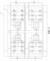
FIG. 1 is a schematic diagram of a structure of a battery self-heating apparatus according to an exemplary embodiment of the present disclosure; -
FIG. 2 is a schematic diagram of a structure of a battery self-heating apparatus according to still another exemplary embodiment of the present disclosure; -
FIG. 3 is a schematic diagram of a structure of a battery self-heating apparatus according to still another exemplary embodiment of the present disclosure; -
FIG. 4 is a schematic diagram of a structure of a battery self-heating apparatus according to still another exemplary embodiment of the present disclosure; -
FIG. 5 is a schematic diagram of a structure of a battery self-heating apparatus according to still another exemplary embodiment of the present disclosure; -
FIG. 6 is a schematic diagram of a structure of a battery self-heating apparatus according to still another exemplary embodiment of the present disclosure; -
FIG. 7 is a schematic diagram of terminal points of a seventh switch and an eighth switch in a battery self-heating apparatus according to still another exemplary embodiment of the present disclosure; -
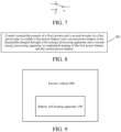
FIG. 8 is a flowchart of a battery self-heating method according to an exemplary embodiment of the present disclosure; and -
FIG. 9 is a structural block diagram of an electric vehicle according to an exemplary embodiment of the present disclosure. -
- 1
First power battery 2 second power battery - 3 third power battery 4 fourth power battery
- 10 first
energy processing apparatus 20 second energy processing apparatus - 30 third
energy processing apparatus 40 fourth energy processing apparatus - 50 fifth
energy processing apparatus 60 sixth energy processing apparatus - 11
first inverter 21 second inverter - 31 third inverter 41 fourth inverter
- 51
fifth inverter 61 sixth inverter - 12
first motor 22 second motor - 32 third motor 42 fourth motor
- 52
fifth motor 62 sixth motor - 13 first
neutral point 23 second neutral point - 33 third
neutral point 43 fourth neutral point - 53 fifth
neutral point 63 sixth neutral point - K1 first switch K2 second switch
- K3 third switch K4 fourth switch
- K5 fifth switch K6 sixth switch
- K7 seventh switch K8 eighth switch
- 100 battery self-
heating apparatus 900 vehicle - Specific implementations of the present disclosure are described in detail below with reference to the accompanying drawings. It should be understood that the specific implementations described herein are merely used to describe and explain the present disclosure, but are not intended to limit the present disclosure.
- It should be noted that, all actions to obtain signals, information, or data in the present disclosure are performed in compliance with corresponding data protection regulations and policies of a country, and with authorization from an owner of a corresponding apparatus.
-
FIG. 1 is a schematic diagram of a structure of a battery self-heating apparatus according to an exemplary embodiment of the present disclosure. As shown inFIG. 1 , the apparatus includes a firstenergy processing apparatus 10, a secondenergy processing apparatus 20, and a controller (not shown) connected to each other. The firstenergy processing apparatus 10 includes afirst inverter 11 and afirst motor 12, and the secondenergy processing apparatus 20 includes asecond inverter 21 and asecond motor 22. A first bus terminal of thefirst inverter 11 is connected to a positive electrode of afirst power battery 1, a second bus terminal of thefirst inverter 11 is connected to a negative electrode of thefirst power battery 1, a negative electrode of asecond power battery 2, and a second bus terminal of thesecond inverter 21. A first terminal of thefirst motor 12 is connected to a midpoint of thefirst inverter 11, a first terminal of thesecond motor 22 is connected to a midpoint of thesecond inverter 21, and a second terminal of thefirst motor 12 is commonly connected to form a firstneutral point 13, and the first neutral point is connected to a secondneutral point 23 formed by commonly connecting a second terminal of thesecond motor 22, through a neutral line. The controller is configured to control connect/disconnect of thefirst inverter 11 and thesecond inverter 21 in a first preset state, to enable thefirst power battery 1 and thesecond power battery 2 to be charged/discharged through the firstenergy processing apparatus 10 and the secondenergy processing apparatus 20, to implement heating of thefirst power battery 1 and thesecond power battery 2. - Both the
first power battery 1 and thesecond power battery 2 shown inFIG. 1 may be power batteries in a same electric vehicle. The firstenergy processing apparatus 10 and the secondenergy processing apparatus 20 may also be components of the same electric vehicle. The electric vehicle may include an electric or hybrid vehicle, ship, airplane, or the like. The following descriptions mainly use the vehicle as an example. For example, a current four-wheel drive electric vehicle mostly uses a system with dual motors and dual electronic controls. Thefirst inverter 11 may be an inverter in a first motor controller in the vehicle. Thefirst motor 12 may be a first motor controlled by the first motor controller in the vehicle. Thesecond inverter 21 may be an inverter in a second motor controller in the vehicle. Thesecond motor 22 may be a second motor controlled by the second motor controller in the vehicle. - The first preset state may be a state in which the
first power battery 1 and thesecond power battery 2 need to be heated. For example, a power of thefirst power battery 1 and a power of thesecond power battery 2 are lower than a preset power threshold, or a temperature of thefirst power battery 1 and a temperature of thesecond power battery 2 are lower than a preset temperature threshold. - The controller controls connect/disconnect of the
first inverter 11 and thesecond inverter 21 in the first preset state, so that an oscillating current is generated between thefirst power battery 1 and thesecond power battery 2 through the firstenergy processing apparatus 10 and the secondenergy processing apparatus 20, to enable thefirst power battery 1 and thesecond power battery 2 to be charged/discharged, to implement heating of thefirst power battery 1 and thesecond power battery 2. In this way, in comparison to a solution in which only a single motor and a single electronic control in the vehicle are used to perform battery self-heating, when the two motors and the two electronic controls in the vehicle are included in a battery oscillation heating process, an added motor and an added electronic control further generate heat in the self-heating process, and the heat generated is at least twice the heat generated by an original single motor and single electronic control for self-heating, which may greatly improve battery self-heating efficiency. In addition, due to a high increase in heat production, when there is excess heating heat needed by the battery, the excess heat may be further exported through a heat pump, to provide a heat source for a vehicle passenger compartment, thereby reducing energy that needs to be consumed when the vehicle passenger compartment is heated. In addition, because both the firstenergy processing apparatus 10 and the secondenergy processing apparatus 20 may be original components in the vehicle, existing components in the vehicle may be fully used to heat a power battery of the vehicle, thereby reducing costs. - Bridge arms in the
first inverter 11 and thesecond inverter 21 may be three-phase bridge arms as shown inFIG. 1 , or may be bridge arms of other quantities. The bridge arms inFIG. 1 are only illustrative. A quantity of motor windings included in thefirst motor 12 and thesecond motor 22 respectively corresponds to the quantity of bridge arms in thefirst inverter 11 and thesecond inverter 21. - An example in which the bridge arms in the
first inverter 11 and thesecond inverter 21 shown inFIG. 1 are three-phase bridge arms, and thefirst motor 12 and thesecond motor 22 include three motor windings (L1, L2, L3, L4, L5, and L6 respectively) is used. The controller may control upper bridge arms of thefirst inverter 11 and lower bridge arms of thesecond inverter 21 to be simultaneously closed in the first preset state, or control lower bridge arms of thefirst inverter 11 and upper bridge arms of thesecond inverter 21 to be simultaneously closed, to implement self-heating of thefirst power battery 1 and thesecond power battery 2. In the heating period, current states in the firstenergy processing apparatus 10 and the secondenergy processing apparatus 20 may include the following four states. - State 1: Three upper bridge arms (D1, D2, and D3) in the
first inverter 11 and three lower bridge arms (E4, E5, and E6) in thesecond inverter 21 are controlled to be closed. Three lower bridge arms (D4, D5, and D6) in thefirst inverter 11 and three upper bridge arms (E1, E2, and E3) in thesecond inverter 21 are controlled to be opened. Thefirst power battery 1 is discharged externally, and thefirst motor 12 and thesecond motor 22 store energy. A current flows out from the positive electrode of thefirst power battery 1, flows to thefirst motor 12 through the three upper bridge arms (D1, D2, and D3) in thefirst inverter 11, then flows out from thesecond motor 22 through a neutral line between thefirst motor 12 and thesecond motor 22, and flows back to the negative electrode of thefirst power battery 1 through the three lower bridge arms (E4, E5, and E6) in thesecond inverter 21. In this state, thefirst power battery 1 is discharged, thefirst motor 12 and thesecond motor 22 are charged, and a voltage in thefirst power battery 1 drops. - State 2: The three lower bridge arms (D4, D5, and D6) in the
first inverter 11 and the three upper bridge arms (E1, E2, and E3) in thesecond inverter 21 are controlled to be closed. The three upper bridge arms (D1, D2, and D3) in thefirst inverter 11 and the three lower bridge arms (E4, E5, and E6) in thesecond inverter 21 are controlled to be opened. Because the current on the motor winding 20 cannot change suddenly, currents in thefirst motor 12 and thesecond motor 22 continue to flow. The freewheeling currents flow through diodes connected in anti-parallel in the three upper bridge arms (E1, E2, and E3) in thesecond inverter 21, flow into a positive electrode of thesecond power battery 2, and charge thesecond power battery 2. Charging currents then flow out from the negative electrode of thesecond power battery 2, flow through diodes connected in anti-parallel in the three lower bridge arms (D4, D5, and D6) in thefirst inverter 11, and return to thefirst motor 12 and thesecond motor 22. In this state, thefirst motor 12 and thesecond motor 22 are discharged, thesecond power battery 2 is charged, thefirst motor 12 and thesecond motor 22 release the electric energy stored in a previous state, and the electric energy is transferred to thesecond power battery 2. A voltage in thefirst motor 12 and a voltage in thesecond motor 22 drop, and a voltage of thesecond power battery 2 rises. - State 3: A connect/disconnect state in the
first inverter 11 and a connect/disconnect state in thesecond inverter 21 remain unchanged. In this case, the voltage of thesecond power battery 2 reaches a highest level, and the current flows out from the positive electrode of thesecond power battery 2. The current flows through the three upper bridge arms (E1, E2, and E3) in thesecond inverter 21, thesecond motor 22, thefirst motor 12, and the three lower bridge arms (D4, D5, and D6) in thefirst inverter 11, and finally flows back to the negative electrode of thesecond power battery 2. In this state, thesecond power battery 2 is discharged, and the voltage drops. The released electric energy is stored in thefirst motor 12 and thesecond motor 22. Thefirst motor 12 and thesecond motor 22 are charged, and the voltage rises. - State 4: The three upper bridge arms (D1, D2, and D3) in the
first inverter 11 and the three lower bridge arms (E4, E5, and E6) in thesecond inverter 21 are controlled to be closed. The three lower bridge arms (D4, D5, and D6) in thefirst inverter 11 and the three upper bridge arms (E1, E2, and E3) in thesecond inverter 21 are controlled to be opened. Currents in thefirst motor 12 and thesecond motor 22 continue to flow. The freewheeling currents flow through diodes connected in anti-parallel in the three upper bridge arms (D1, D2, and D3) in thefirst inverter 11, flow into the positive electrode of thefirst power battery 1, and charge thefirst power battery 1. Charging currents then flow out from the negative electrode of thefirst power battery 1, flow through diodes connected in anti-parallel in the three lower bridge arms (E4, E5, and E6) of thesecond inverter 21, and return to thefirst motor 12 and thesecond motor 22. In this state, thefirst motor 12 and thesecond motor 22 are discharged, and the voltage drops. Thefirst power battery 1 is charged, and the voltage rises. - In the battery self-heating process, both the
first power battery 1 and thesecond power battery 2 undergo charging and discharging processes, so that a self-heating effect may be implemented through both thefirst power battery 1 and thesecond power battery 2. - In addition, in a common circuit including a motor, a current flowing through the motor needs to have different directions at any moment, to ensure that a sum of currents entering a neutral point (N point) of the motor is equal to a sum of currents flowing out of a neutral point of the motor. For example, it may be one phase in and one phase out, or one phase in and two phases out, or one phase out and two phases in. Therefore, a maximum current passing through a conventional motor may be only a current limit of one phase of the motor winding. In the schematic diagram of the battery self-heating apparatus shown in
FIG. 1 , because both thefirst motor 12 and thesecond motor 22 may draw the current through the neutral line connected between thefirst motor 12 and thesecond motor 22, so that currents in the three-phase motor windings in thefirst motor 12 and thesecond motor 22 may flow in a same direction. As a result, magnitudes of currents that can pass through thefirst motor 12 and thesecond motor 22 are greatly increased, and a maximum overcurrent capacity of the motor may be fully utilized. The greater the current, more heat is generated in thefirst power battery 1 and thesecond power battery 2, and therefore, battery self-heating efficiency implemented in this embodiment may be further improved. - In addition, the bridge arms in the
first inverter 11 and thesecond inverter 21 shown inFIG. 1 are three-phase bridge arms, and when each of thefirst motor 12 and thesecond motor 22 includes three motor windings, if the currents in the three motor windings in each of thefirst motor 12 and thesecond motor 22 are in a same direction, the currents in the three motor windings are equal in magnitude. An electromagnetic force synthesized in the motor is zero in real time, thereby implementing an output of zero torque. This may ensure that the motor remains static in the battery self-heating process without any additional torque control. - Through the foregoing technical solution, a battery self-heating apparatus that performs low-frequency oscillation heating by using dual motors and dual electric controls is provided, which may fully use characteristics that some electric vehicles such as a four-wheel drive electric vehicle have the dual motors and the dual electric controls. By connecting the dual motors through the neutral line, self-heating efficiency and a power of the power battery are greatly improved, and a lower cost is ensured.
-
FIG. 2 is a schematic diagram of a structure of a battery self-heating apparatus according to still another exemplary embodiment of the present disclosure. As shown inFIG. 2 , the apparatus further includes: a first switch K1, the first switch K1 being connected between the firstneutral point 13 and the secondneutral point 23, and when the first switch K1 is closed, the firstneutral point 13 being connected to the secondneutral point 23; and the controller, being configured to control the first switch K1 to be closed in the first preset state. In other words, thefirst motor 12 is connected to thesecond motor 22 in the first preset state, to enable thefirst power battery 1 and thesecond power battery 2 to be charged/discharged through the firstenergy processing apparatus 10 and the secondenergy processing apparatus 20, to implement heating of thefirst power battery 1 and thesecond power battery 2. - In a possible implementation, as shown in
FIG. 2 , the apparatus further includes: a second switch K2, the second switch K2 being connected to the positive electrode of thefirst power battery 1, a positive electrode of thesecond power battery 2, the first bus terminal of thefirst inverter 11, and a first bus terminal of thesecond inverter 21, and when the second switch K2 is closed, the positive electrode of thefirst power battery 1, the positive electrode of thesecond power battery 2, the first bus terminal of thefirst inverter 11, and the first bus terminal of thesecond inverter 21 being closed; and the controller, being configured to control the first switch K1 to be opened and control the second switch K2 to be closed in a second preset state, to enable an external power supply to charge thefirst power battery 1 and thesecond power battery 2. The second preset state may be a state in which thefirst power battery 1 and thesecond power battery 2 need to be charged. For example, the vehicle has established a connection with an external charging pile, or the power of thefirst power battery 1 and the power of thesecond power battery 2 are lower than the preset power threshold. In this case, thefirst power battery 1 and thesecond power battery 2 are separately charged as independent battery packs. - In a possible implementation, the
first motor 12 and thesecond motor 22 may be drive motors in the vehicle, and the controller is configured to control the first switch K1 and the second switch K2 to be opened in a third preset state, to enable thefirst power battery 1 and thesecond power battery 2 to drive the vehicle through thefirst motor 12 and thesecond motor 22 respectively. The third preset state is also a state in which the vehicle needs to run normally. In this state, by controlling the first switch K1 and the second switch K2 to be opened, thefirst motor 12 and thesecond motor 22 may be enabled to separately complete corresponding driving functions. - In addition, based on heating the battery in the vehicle by using dual motors and dual electronic controls to implement an oscillation heating circuit, more motors and motor controllers may be further added to the circuit to further enhance a battery self-heating effect. For example,
FIG. 3 and FIG. 4 below separately show two schematic diagrams of structures of battery self-heating circuits that may be formed when there are two power batteries in the vehicle and there are three motors and three motor controllers. -
FIG. 3 is a schematic diagram of a structure of a battery self-heating apparatus according to still another exemplary embodiment of the present disclosure. As shown inFIG. 3 , the apparatus further includes a thirdenergy processing apparatus 30 and a third switch K3. The thirdenergy processing apparatus 30 includes a third inverter 31 and athird motor 32, a first bus terminal of the third inverter 31 is connected to the positive electrode of thesecond power battery 2, the first bus terminal of thesecond inverter 21, and the second switch K2, and a second bus terminal of the third inverter 31 is connected to the negative electrode of thefirst power battery 1, the negative electrode of thesecond power battery 2, the second bus terminal of thefirst inverter 11, and the second bus terminal of thesecond inverter 21, a first terminal of thethird motor 32 is connected to a midpoint of the third inverter 31, a second terminal of thethird motor 32 is commonly connected to form a third neutral point 33, and the third neutral point 33 is connected to the first switch K1 and the secondneutral point 23 through the third switch K3. The controller is configured to control the first switch K1 and the third switch K3 to be closed and the second switch K2 to be opened in the first preset state, and control connect/disconnect of thefirst inverter 11, thesecond inverter 21, and the third inverter 31, to enable thefirst power battery 1 and thesecond power battery 2 to be charged/discharged through the firstenergy processing apparatus 10, the secondenergy processing apparatus 20, and the thirdenergy processing apparatus 30, to implement heating of thefirst power battery 1 and thesecond power battery 2. - In this embodiment, the third
energy processing apparatus 30 is connected to thesecond power battery 2 together with the second energy processing apparatus. In the first preset state, the controller may control the first switch K1 and the third switch K3 to be closed, and control the second switch K2 to be opened, to form a battery self-heating apparatus including the firstenergy processing apparatus 10, the secondenergy processing apparatus 20, and the thirdenergy processing apparatus 30. A direction and a principle of a self-heating current of the battery self-heating apparatus are the same as those described in the embodiment shown inFIG. 1 . Connect/disconnect of the upper bridge arm and connect/disconnect of the lower bridge arm in the thirdenergy processing apparatus 30 are consistent with connect/disconnect of the upper bridge arm and connect/disconnect of the lower bridge arm in the secondenergy processing apparatus 20. The thirdenergy processing apparatus 30 and the secondenergy processing apparatus 20 as a whole jointly form a current loop with the firstenergy processing apparatus 10, to implement charging/discharging of thefirst power battery 1 and thesecond power battery 2 in the foregoing four states. In the second preset state, the first switch K1 and the third switch K3 may be opened, and the second switch K2 may be closed, to enable an external charging device such as a charging pile to simultaneously charge thefirst power battery 1 and thesecond power battery 2 separately. In the third preset state, the first switch K1, the second switch K2, and the third switch K3 may be opened, to enable three motors in the firstenergy processing apparatus 10, the secondenergy processing apparatus 20, and the thirdenergy processing apparatus 30 to separately provide drive for the vehicle. -
FIG. 4 is a schematic diagram of a structure of a battery self-heating apparatus according to still another exemplary embodiment of the present disclosure. As shown inFIG. 4 , the apparatus further includes a fourthenergy processing apparatus 40 and a fourth switch K4. The fourthenergy processing apparatus 40 includes a fourth inverter 41 and a fourth motor 42, a first bus terminal of the fourth inverter 41 is connected to the positive electrode of thefirst power battery 1, the first bus terminal of thefirst inverter 11, and the second switch K2, a second bus terminal of the fourth inverter 41 is connected to the negative electrode of thefirst power battery 1, the negative electrode of thesecond power battery 2, the second bus terminal of thefirst inverter 11, and the second bus terminal of thesecond inverter 21, a first terminal of the fourth motor 42 is connected to a midpoint of the fourth inverter 41, a second terminal of the fourth motor 42 is commonly connected to form a fourthneutral point 43, and the fourthneutral point 43 is connected to the first switch K1 and the firstneutral point 13 through the fourth switch K4. The controller is configured to control the first switch K1 and the fourth switch K4 to be closed and control the second switch K2 to be opened in the first preset state, and control connect/disconnect of thefirst inverter 11, thesecond inverter 21, and the fourth inverter 41, to enable thefirst power battery 1 and thesecond power battery 2 to be charged/discharged through the firstenergy processing apparatus 10, the secondenergy processing apparatus 20, and the fourthenergy processing apparatus 40, to implement heating of thefirst power battery 1 and thesecond power battery 2. - In this embodiment, the fourth
energy processing apparatus 40 is connected to thefirst power battery 1 together with the firstenergy processing apparatus 10. In the first preset state, the first switch K1 and the fourth switch K4 are controlled to be closed, and the second switch K2 is controlled to be opened, to form a battery self-heating apparatus including the firstenergy processing apparatus 10, the secondenergy processing apparatus 20, and the fourthenergy processing apparatus 40. A direction and a principle of a self-heating current of the battery self-heating apparatus are the same as those described in the embodiment shown inFIG. 1 . Connect/disconnect of the upper bridge arm and connect/disconnect of the lower bridge arm in the fourthenergy processing apparatus 40 are consistent with connect/disconnect of the upper bridge arm and connect/disconnect of the lower bridge arm in the firstenergy processing apparatus 10. The fourthenergy processing apparatus 40 and the firstenergy processing apparatus 10 as a whole jointly form a current loop with the secondenergy processing apparatus 20, to implement charging/discharging of thefirst power battery 1 and thesecond power battery 2 in the foregoing four states. In the second preset state, the first switch K1 and the fourth switch K4 may be opened, and the second switch K2 may be closed, to enable an external charging device such as a charging pile to simultaneously charge thefirst power battery 1 and thesecond power battery 2 separately. In the third preset state, the first switch K1, the second switch K2, and the fourth switch K4 may be opened, to enable three motors in the firstenergy processing apparatus 10, the secondenergy processing apparatus 20, and the fourthenergy processing apparatus 40 to separately provide drive for the vehicle. - In a possible implementation, the third inverter 31 and the fourth inverter 41 shown in
FIG. 3 and FIG. 4 may respectively include three sets of bridge arms. Each of thethird motor 32 and the fourth motor 42 may also be a three-phase motor, and includes three motor windings. In addition, in the first preset state, currents in the three motor windings in each of thethird motor 32 and the fourth motor 42 are also in a same direction at each moment. Therefore, when the battery self-heating apparatus shown inFIG. 3 and FIG. 4 performs self-heating of thefirst power battery 1 and thesecond power battery 2 in the first preset state, a maximum overcurrent capacity of thethird motor 32 and the fourth motor 42 may also be fully exerted, to generate more heat, and further improve the battery self-heating efficiency. In addition, when each of thethird motor 32 and the fourth motor 42 includes the three motor windings, if the currents are in the same direction, the currents in the three motor windings in each of the motors are equal in magnitude. An electromagnetic force synthesized in the motor is zero in real time, thereby also implementing an output of zero torque. This ensures that the motor remains static in the battery self-heating process without any additional torque control. - In addition, based on heating the battery in the vehicle by using dual motors and dual electronic controls to implement an oscillation heating circuit, more power batteries, motors, and motor controllers may be further used to further enhance a battery self-heating effect. For example,
FIG. 5 andFIG. 6 below show two schematic diagrams of structures of battery self-heating circuits that may be formed when there are four power batteries in the vehicle and there are four motors and four motor controllers. -
FIG. 5 is a schematic diagram of a structure of a battery self-heating apparatus according to still another exemplary embodiment of the present disclosure. As shown inFIG. 5 , the apparatus further includes a fifthenergy processing apparatus 50 and a sixthenergy processing apparatus 60. The fifthenergy processing apparatus 50 includes afifth inverter 51 and afifth motor 52, and the sixthenergy processing apparatus 60 includes asixth inverter 61 and asixth motor 62. A first bus terminal of thefifth inverter 51 is connected to the negative electrode of thefirst power battery 1, the negative electrode of thesecond power battery 2, a positive electrode of athird power battery 3, a positive electrode of a fourth power battery 4, the second bus terminal of thefirst inverter 11, and the second bus terminal of thesecond inverter 21. A second bus terminal of thefifth inverter 51 is connected to a negative electrode of thethird power battery 3, a negative electrode of a fourth power battery 4, and a second bus terminal of thesixth inverter 61. A first terminal of thefifth motor 52 is connected to a midpoint of thefifth inverter 51, a first terminal of thesixth motor 62 is connected to a midpoint of thesixth inverter 61, and a second terminal of thefifth motor 52 is commonly connected to form a fifthneutral point 53, and is connected to a sixthneutral point 63 formed by commonly connecting a second terminal of thesixth motor 62. The controller is configured to control the first switch K1 to be closed and control the second switch K2 to be opened in the first preset state, and control connect/disconnect of thefirst inverter 11, thesecond inverter 21, thefifth inverter 51, and thesixth inverter 61, to enable thefirst power battery 1, thesecond power battery 2, thethird power battery 3, and the fourth power battery 4 to be charged/discharged through the firstenergy processing apparatus 10, the secondenergy processing apparatus 20, the fifthenergy processing apparatus 50, and the sixthenergy processing apparatus 60, to implement heating of thefirst power battery 1, thesecond power battery 2, thethird power battery 3, and the fourth power battery 4. - In the first preset state, in this embodiment, an implementation for implementing battery self-heating is: controlling connect/disconnect of the
first inverter 11, thesecond inverter 21, the third inverter 31, and the fourth inverter 41 in the first preset state, to enable thefirst power battery 1 and thesecond power battery 2 to be charged/discharged through the firstenergy processing apparatus 10 and the secondenergy processing apparatus 20, and to enable thethird power battery 3 and the fourth power battery 4 to be charged/discharged through the fifthenergy processing apparatus 50 and the sixthenergy processing apparatus 60, to implement heating of thefirst power battery 1, thesecond power battery 2, thethird power battery 3, and the fourth power battery 4. In other words, thefirst power battery 1 and thesecond power battery 2 are used as a charging/discharging group, thethird power battery 3 and the fourth power battery 4 are used as a charging/discharging group, and each forms a self-heating apparatus that can perform self-heating on the power battery in the group. A direction and a principle of self-heating currents in each group are the same as those described in the embodiment shown inFIG. 1 . This is not described herein again. - In addition, in this case, due to a small space in a battery pack, if there are multiple power batteries in the battery pack, and voltages between the multiple power batteries cannot be balanced, a specific potential difference is generated. Once the potential difference is generated, a current is generated. Because resistance in the battery pack is small, the current generated by the potential difference has a large impact on the battery pack, and the battery pack is prone to be burned out. Therefore, when multiple groups of power batteries are charged/discharged, power batteries belonging to a side may be considered as a whole, and an overall voltage of power batteries on each side may always be ensured to remain stable, to avoid generating the potential difference. For example, in the schematic diagram shown in
FIG. 5 , thefirst power battery 1 and thethird power battery 3 may be considered as a whole, and thesecond power battery 2 and the fourth power battery 4 may be considered as a whole. When charging/discharging of each power battery is separately controlled, it is ensured that when thefirst power battery 1 charges thesecond power battery 2, the fourth power battery 4 charges thethird power battery 3, and when thesecond power battery 2 charges thefirst power battery 1, thethird power battery 3 charges the fourth power battery 4. Therefore, it may be ensured that a total voltage of thefirst power battery 1 and thethird power battery 3, and a total voltage of thesecond power battery 2 and the fourth power battery 4 may remain stable. A safety risk of the battery pack caused by the potential difference is reduced. - Based on the schematic diagram of the structure of the battery self-heating apparatus shown in
FIG. 5 , to further implement functions of battery pack charging and motor driving, a schematic diagram of a structure of a battery self-heating apparatus shown inFIG. 6 is provided. -
FIG. 6 is a schematic diagram of a structure of a battery self-heating apparatus according to still another exemplary embodiment of the present disclosure. As shown inFIG. 6 , the apparatus further includes a fifth switch K5, a sixth switch K6, a seventh switch K7, and an eighth switch K8. The fifth switch K5 is connected between the fifthneutral point 53 and the sixthneutral point 63, and when the fourth switch K4 is closed, the fourthneutral point 43 is connected to the fifthneutral point 53. A first terminal of the sixth switch K6 is connected to a first bus terminal of thefifth inverter 51 and a first terminal of the eighth switch K8, a second terminal of the sixth switch K6 is connected to a first bus terminal of thesixth inverter 61, the second bus terminal of thesecond inverter 21, the second bus terminal of thefirst inverter 11, the negative electrode of thesecond power battery 2, the positive electrode of the fourth power battery 4, and a first terminal of the seventh switch K7, and when the sixth switch K6 is closed, the first terminal of the sixth switch K6 is connected to the second terminal of the sixth switch K6. A second terminal of the seventh switch K7 is connected to the second bus terminal of thefifth inverter 51, the second bus terminal of thesixth inverter 61, the negative electrode of thethird power battery 3, and the negative electrode of the fourth power battery 4. A third terminal of the seventh switch K7 is connected to the negative electrode of thefirst power battery 1, the positive electrode of thethird power battery 3, and a second terminal of the eighth switch K8. A third terminal of the eighth switch K8 is connected to the first bus terminal of thefirst inverter 11, the second switch K2, and the positive electrode of thefirst power battery 1. - Terminal points of the seventh switch K7 and the eighth switch K8 are sorted as shown in
FIG. 7 , and are determined as a first terminal a, a second terminal b, and a third terminal c in clockwise order. - According to the schematic diagram of the structure shown in
FIG. 5 , in the first preset state, the controller inFIG. 6 should control the first switch K1 and the fifth switch K5 to be closed, control the second switch K2 and the sixth switch K6 to be opened, control the first terminal of the seventh switch K7 to be connected to the third terminal of the seventh switch K7, and control the first terminal of the eighth switch K8 to be connected to the second terminal of the eighth switch K8. In this way, connect/disconnect of thefirst inverter 11, thesecond inverter 21, thefifth inverter 51, and thesixth inverter 61 is controlled, to implement heating of thefirst power battery 1, thesecond power battery 2, thethird power battery 3, and the fourth power battery 4. - In addition, the controller in
FIG. 6 is further configured to control the first switch K1 and the fifth switch K5 to be opened, and control the second switch K2 and the sixth switch K6 to be closed in the second preset state, control the first terminal of the seventh switch K7 to be connected to the second terminal of the seventh switch K7, and control the first terminal of the eighth switch K8 to be connected to the third terminal of the eighth switch K8, to enable the external power supply to charge thefirst power battery 1, thesecond power battery 2, thethird power battery 3, and the fourth power battery 4. - In addition, when the
first motor 12, thesecond motor 22, thethird motor 32, and the fourth motor 42 that are shown inFIG. 6 respectively are drive motors in a vehicle, the controller inFIG. 6 is further configured to control the first switch K1, the second switch K2, and the fifth switch K5, and the sixth switch K6 to be opened in a third preset state, control the first terminal of the seventh switch K7 to be connected to the third terminal of the seventh switch K7, and control the first terminal of the eighth switch K8 to be connected to the second terminal of the eighth switch K8, to enable thefirst power battery 1, thesecond power battery 2, thethird power battery 3, and the fourth power battery 4 to drive the vehicle through thefirst motor 12, thesecond motor 22, thethird motor 32, and the fourth motor 42 respectively. - In a possible implementation, the
fifth inverter 51 and thesixth inverter 61 shown inFIG. 5 andFIG. 6 may also respectively include three sets of bridge arms. Each of thefifth motor 52 and thesixth motor 62 may also be a three-phase motor, and includes three motor windings. In addition, in the first preset state, currents in the three motor windings in each of thefifth motor 52 and thesixth motor 62 are also in a same direction at each moment. Therefore, when the battery self-heating apparatus shown inFIG. 5 andFIG. 6 performs self-heating of thefirst power battery 1 and thesecond power battery 2 in the first preset state, a maximum overcurrent capacity of thefifth motor 52 and thesixth motor 62 may also be fully exerted, to generate more heat, and further improve the battery self-heating efficiency. In addition, when each of thefifth motor 52 and thesixth motor 62 includes three motor windings, if the currents are in the same direction, the currents in the three motor windings in each of the motors are equal in magnitude. An electromagnetic force synthesized in the motor is zero in real time, thereby also implementing an output of zero torque. This also ensures that the motor remains static in the battery self-heating process without any additional torque control. -
FIG. 8 is a flowchart of a battery self-heating method according to an exemplary embodiment of the present disclosure. As shown inFIG. 8 , the method includesstep 801. - In
step 801, connect/disconnect of thefirst inverter 11 and thesecond inverter 21 is controlled in a first preset state, to enable thefirst power battery 1 and thesecond power battery 2 to be charged/discharged through the firstenergy processing apparatus 10 and the secondenergy processing apparatus 20, to implement heating of thefirst power battery 1 and thesecond power battery 2. The firstenergy processing apparatus 10 includes afirst inverter 11 and afirst motor 12, and the secondenergy processing apparatus 20 includes asecond inverter 21 and asecond motor 22. A first bus terminal of thefirst inverter 11 is connected to a positive electrode of afirst power battery 1, a second bus terminal of thefirst inverter 11 is connected to a negative electrode of thefirst power battery 1, a negative electrode of asecond power battery 2, and a second bus terminal of thesecond inverter 21. A first terminal of thefirst motor 12 is connected to a midpoint of thefirst inverter 11, a first terminal of thesecond motor 22 is connected to a midpoint of thesecond inverter 21, and a second terminal of thefirst motor 12 is commonly connected to form a firstneutral point 13, and the firstneutral point 13 is connected to a secondneutral point 23 formed by commonly connecting a second terminal of thesecond motor 22, through a neutral line. - Through the foregoing technical solution, a battery self-heating apparatus that performs low-frequency oscillation heating by using dual motors and dual electric controls is provided, which may fully use characteristics that some electric vehicles such as a four-wheel drive electric vehicle have the dual motors and the dual electric controls. By connecting the dual motors through the neutral line, self-heating efficiency and a power of the power battery are greatly improved, and a lower cost is ensured.
- In a possible implementation, the method further includes: controlling the first switch K1 to be closed in the first preset state. The first switch K1 is connected between the first
neutral point 13 and the secondneutral point 23, and when the first switch K1 is closed, the firstneutral point 13 is connected to the secondneutral point 23. - In a possible implementation, the method further includes: controlling the first switch K1 to be opened and controlling the second switch K2 to be closed in a second preset state, to enable an external power supply to charge the
first power battery 1 and thesecond power battery 2. The second switch K2 is connected to the positive electrode of thefirst power battery 1, a positive electrode of thesecond power battery 2, the first bus terminal of thefirst inverter 11, and a first bus terminal of thesecond inverter 21, and when the second switch K2 is closed, the positive electrode of thefirst power battery 1, the positive electrode of thesecond power battery 2, the first bus terminal of thefirst inverter 11, and the first bus terminal of thesecond inverter 21 are closed. - In a possible implementation, the method further includes: controlling an upper bridge arm of the
first inverter 11 and a lower bridge arm of thesecond inverter 21 to be simultaneously closed in the first preset state, or controlling a lower bridge arm of thefirst inverter 11 and an upper bridge arm of thesecond inverter 21 to be simultaneously closed, to enable thefirst power battery 1 and thesecond power battery 2 to be charged/discharged through the firstenergy processing apparatus 10 and the secondenergy processing apparatus 20, to implement heating of thefirst power battery 1 and thesecond power battery 2. - In a possible implementation, the method further includes: controlling the first switch K1 and the third switch K3 to be closed and the second switch K2 to be opened in the first preset state, and controlling connect/disconnect of the
first inverter 11, thesecond inverter 21, and the third inverter 31, to enable thefirst power battery 1 and thesecond power battery 2 to be charged/discharged through the firstenergy processing apparatus 10, the secondenergy processing apparatus 20, and the thirdenergy processing apparatus 30, to implement heating of thefirst power battery 1 and thesecond power battery 2. The thirdenergy processing apparatus 30 includes a third inverter 31 and athird motor 32, a first bus terminal of the third inverter 31 is connected to the positive electrode of thesecond power battery 2, the first bus terminal of thesecond inverter 21, and the second switch K2, and a second bus terminal of the third inverter 31 is connected to the negative electrode of thefirst power battery 1, the negative electrode of thesecond power battery 2, the second bus terminal of thefirst inverter 11, and the second bus terminal of thesecond inverter 21, a first terminal of thethird motor 32 is connected to a midpoint of the third inverter 31, a second terminal of thethird motor 32 is commonly connected to form a third neutral point 33, and the third neutral point 33 is connected to the first switch K1 and the secondneutral point 23 through the third switch K3. - In a possible implementation, the method further includes: controlling the first switch K1 and the fourth switch K4 to be closed and controlling the second switch K2 to be opened in the first preset state, and controlling connect/disconnect of the
first inverter 11, thesecond inverter 21, and the fourth inverter 41, to enable thefirst power battery 1 and thesecond power battery 2 to be charged/discharged through the firstenergy processing apparatus 10, the secondenergy processing apparatus 20, and the fourthenergy processing apparatus 40, to implement heating of thefirst power battery 1 and thesecond power battery 2. The fourthenergy processing apparatus 40 includes a fourth inverter 41 and a fourth motor 42, a first bus terminal of the fourth inverter 41 is connected to the positive electrode of thefirst power battery 1, the first bus terminal of thefirst inverter 11, and the second switch K2, a second bus terminal of the fourth inverter 41 is connected to the negative electrode of thefirst power battery 1, the negative electrode of thesecond power battery 2, the second bus terminal of thefirst inverter 11, and the second bus terminal of thesecond inverter 21, a first terminal of the fourth motor 42 is connected to a midpoint of the fourth inverter 41, a second terminal of the fourth motor 42 is commonly connected to form a fourthneutral point 43, and the fourthneutral point 43 is connected to the first switch K1 and the firstneutral point 13 through the fourth switch K4. - In a possible implementation, the method further includes: controlling the first switch K1 to be closed and controlling the second switch K2 to be opened in the first preset state, and controlling connect/disconnect of the
first inverter 11, thesecond inverter 21, thefifth inverter 51, and thesixth inverter 61, to enable thefirst power battery 1, thesecond power battery 2, thethird power battery 3, and the fourth power battery 4 to be charged/discharged through the firstenergy processing apparatus 10, the secondenergy processing apparatus 20, the fifthenergy processing apparatus 50, and the sixthenergy processing apparatus 60, to implement heating of thefirst power battery 1, thesecond power battery 2, thethird power battery 3, and the fourth power battery 4. The fifthenergy processing apparatus 50 includes afifth inverter 51 and afifth motor 52, and the sixthenergy processing apparatus 60 includes asixth inverter 61 and asixth motor 62. A first bus terminal of thefifth inverter 51 is connected to the negative electrode of thefirst power battery 1, the negative electrode of thesecond power battery 2, a positive electrode of athird power battery 3, a positive electrode of a fourth power battery 4, the second bus terminal of thefirst inverter 11, and the second bus terminal of thesecond inverter 21. A second bus terminal of thefifth inverter 51 is connected to a negative electrode of thethird power battery 3, a negative electrode of a fourth power battery 4, and a second bus terminal of thesixth inverter 61. A first terminal of thefifth motor 52 is connected to a midpoint of thefifth inverter 51, a first terminal of thesixth motor 62 is connected to a midpoint of thesixth inverter 61, and a second terminal of thefifth motor 52 is commonly connected to form a fifthneutral point 53, and is connected to a sixthneutral point 63 formed by commonly connecting a second terminal of thesixth motor 62. - In a possible implementation, the method further includes: controlling the first switch K1 and the fifth switch K5 to be opened, and controlling the second switch K2 and the sixth switch K6 to be closed in the second preset state, controlling the first terminal of the seventh switch K7 to be connected to the second terminal of the seventh switch K7, and controlling the first terminal of the eighth switch K8 to be connected to the third terminal of the eighth switch K8, to enable the external power supply to charge the
first power battery 1, thesecond power battery 2, thethird power battery 3, and the fourth power battery 4. The fifth switch K5 is connected between the fifthneutral point 53 and the sixthneutral point 63, and when the fourth switch K4 is closed, the fourthneutral point 43 is connected to the fifthneutral point 53. A first terminal of the sixth switch K6 is connected to a first bus terminal of thefifth inverter 51 and a first terminal of the eighth switch K8, a second terminal of the sixth switch K6 is connected to a first bus terminal of thesixth inverter 61, the second bus terminal of thesecond inverter 21, the second bus terminal of thefirst inverter 11, the negative electrode of thesecond power battery 2, the positive electrode of the fourth power battery 4, and a first terminal of the seventh switch K7, and when the sixth switch K6 is closed, the first terminal of the sixth switch K6 is connected to the second terminal of the sixth switch K6. A second terminal of the seventh switch K7 is connected to the second bus terminal of thefifth inverter 51, the second bus terminal of thesixth inverter 61, the negative electrode of thethird power battery 3, and the negative electrode of the fourth power battery 4. A third terminal of the seventh switch K7 is connected to the negative electrode of thefirst power battery 1, the positive electrode of thethird power battery 3, and a second terminal of the eighth switch K8. A third terminal of the eighth switch K8 is connected to the first bus terminal of thefirst inverter 11, the second switch K2, and the positive electrode of thefirst power battery 1. - In a possible implementation, the method further includes: controlling connect/disconnect of the
first inverter 11, thesecond inverter 21, the third inverter 31, and the fourth inverter 41 in the first preset state, to enable thefirst power battery 1 and thesecond power battery 2 to be charged/discharged through the firstenergy processing apparatus 10 and the secondenergy processing apparatus 20, and to enable thethird power battery 3 and the fourth power battery 4 to be charged/discharged through the fifthenergy processing apparatus 50 and the sixthenergy processing apparatus 60, to implement heating of thefirst power battery 1, thesecond power battery 2, thethird power battery 3, and the fourth power battery 4. When thefirst power battery 1 charges thesecond power battery 2, the fourth power battery 4 charges thethird power battery 3, and when thesecond power battery 2 charges thefirst power battery 1, thethird power battery 3 charges the fourth power battery 4. - In a possible implementation, the method further includes: controlling the first switch K1, the second switch K2, the fifth switch K5, and the sixth K6 switch to be opened in a third preset state, controlling the first terminal of the seventh switch K7 to be connected to the third terminal of the seventh switch K7, and controlling the first terminal of the eighth switch K8 to be connected to the second terminal of the eighth switch K8, to enable the
first power battery 1, thesecond power battery 2, thethird power battery 3, and the fourth power battery 4 to drive the vehicle through thefirst motor 12, thesecond motor 22, thethird motor 32, and the fourth motor 42 respectively. Thefirst motor 12, thesecond motor 22, thethird motor 32, and the fourth motor 42 are separately drive motors in the vehicle. - In a possible implementation, the
first inverter 11, thesecond inverter 21, thefifth inverter 51, and thesixth inverter 61 respectively include three sets of bridge arms. Each of thefirst motor 12, thesecond motor 22, thefifth motor 52, and thesixth motor 62 is a three-phase motor, and includes three motor windings, and in the first preset state, currents in the three motor windings in each of thefirst motor 12, thesecond motor 22, thefifth motor 52, and thesixth motor 62 are in a same direction at each moment. - In a possible implementation, the method further includes: exporting, in the first preset state, heat generated by the first power battery and the second power battery to a vehicle passenger compartment through a heat pump to provide a heat source.
-
FIG. 9 is a structural block diagram of anelectric vehicle 900 according to an exemplary embodiment of the present disclosure. As shown inFIG. 9 , theelectric vehicle 900 includes the battery self-heating apparatus 100. The controller in the battery self-heating apparatus 100 may be further configured to perform all or part of steps in the battery self-heating method. A person skilled in the art should know that during specific implementation, thevehicle 900 further includes other components.FIG. 9 shows only parts related to embodiments of the present disclosure, and other necessary vehicle components are not shown one by one. - The preferred implementations of the present disclosure are described above in detail with reference to the accompanying drawings, but the present disclosure is not limited to the specific details in the above implementations. Various simple variations may be made to the technical solutions of the present disclosure within the scope of the technical idea of the present disclosure, and such simple variations shall all fall within the protection scope of the present disclosure.
- It should be additionally noted that, the specific technical features described in the foregoing specific implementations may be combined in any proper manner in a case without conflict. To avoid unnecessary repetition, various possible combination manners are not described in the present disclosure.
- In addition, different implementations of the present disclosure may also be arbitrarily combined without departing from the idea of the present disclosure, and these combinations shall still be considered as content disclosed in the present disclosure.
Claims (14)
- A battery self-heating apparatus, comprising a first energy processing apparatus (10), a second energy processing apparatus (20), and a controller connected to each other, whereinthe first energy processing apparatus comprises a first inverter (11) and a first motor (12), and the second energy processing apparatus comprises a second inverter (21) and a second motor (22); a first bus terminal of the first inverter is connected to a positive electrode of a first power battery (1), a second bus terminal of the first inverter is connected to a negative electrode of the first power battery, a negative electrode of a second power battery (2), and a second bus terminal of the second inverter;a first terminal of the first motor is connected to a midpoint of the first inverter, a first terminal of the second motor is connected to a midpoint of the second inverter, and a second terminal of the first motor is commonly connected to form a first neutral point (13), and the first neutral point (13) is connected to a second neutral point (23) , formed by commonly connecting a second terminal of the second motor, through a neutral line; andthe controller is configured to control connect/disconnect of the first inverter and the second inverter in a first preset state, to enable the first power battery and the second power battery to be charged/discharged through the first energy processing apparatus and the second energy processing apparatus, to implement heating of the first power battery and the second power battery.
- The apparatus according to claim 1, further comprising:a first switch, the first switch being connected between the first neutral point and the second neutral point, and when the first switch is closed, the first neutral point being connected to the second neutral point; andthe controller, being configured to control the first switch to be closed in the first preset state.
- The apparatus according to claim 1 or 2, further comprising:a second switch, the second switch being connected to the positive electrode of the first power battery, a positive electrode of the second power battery, the first bus terminal of the first inverter, and a first bus terminal of the second inverter, and when the second switch is closed, the positive electrode of the first power battery, the positive electrode of the second power battery, the first bus terminal of the first inverter, and the first bus terminal of the second inverter being closed; andthe controller, being configured to control the first switch to be opened and control the second switch to be closed in a second preset state, to enable an external power supply to charge the first power battery and the second power battery.
- The apparatus according to any one of claims 1 to 3, wherein
the controller is configured to control an upper bridge arm of the first inverter and a lower bridge arm of the second inverter to be simultaneously closed in the first preset state, or control a lower bridge arm of the first inverter and an upper bridge arm of the second inverter to be simultaneously closed, to enable the first power battery and the second power battery to be charged/discharged through the first energy processing apparatus and the second energy processing apparatus, to implement heating of the first power battery and the second power battery. - The apparatus according to any one of claims 1 to 4, further comprising a third energy processing apparatus (30) and a third switch, whereinthe third energy processing apparatus comprises a third inverter (31) and a third motor (32), a first bus terminal of the third inverter is connected to the positive electrode of the second power battery, the first bus terminal of the second inverter, and the second switch, and a second bus terminal of the third inverter is connected to the negative electrode of the first power battery, the negative electrode of the second power battery, the second bus terminal of the first inverter, and the second bus terminal of the second inverter;a first terminal of the third motor is connected to a midpoint of the third inverter, a second terminal of the third motor is commonly connected to form a third neutral point (33), and the third neutral point is connected to the first switch and the second neutral point through the third switch; andthe controller is configured to control the first switch and the third switch to be closed and control the second switch to be opened in the first preset state, and control connect/disconnect of the first inverter, the second inverter, and the third inverter, to enable the first power battery and the second power battery to be charged/discharged through the first energy processing apparatus, the second energy processing apparatus, and the third energy processing apparatus, to implement heating of the first power battery and the second power battery.
- The apparatus according to any one of claims 1 to 5, further comprising a fourth energy processing apparatus (40) and a fourth switch, whereinthe fourth energy processing apparatus comprises a fourth inverter (41) and a fourth motor (42), a first bus terminal of the fourth inverter is connected to the positive electrode of the first power battery, the first bus terminal of the first inverter, and the second switch, and a second bus terminal of the fourth inverter is connected to the negative electrode of the first power battery, the negative electrode of the second power battery, the second bus terminal of the first inverter, and the second bus terminal of the second inverter;a first terminal of the fourth motor is connected to a midpoint of the fourth inverter, a second terminal of the fourth motor is commonly connected to form a fourth neutral point (43), and the fourth neutral point is connected to the first switch and the first neutral point through the fourth switch; andthe controller is configured to control the first switch and the fourth switch to be closed and control the second switch to be opened in the first preset state, and control connect/disconnect of the first inverter, the second inverter, and the fourth inverter, to enable the first power battery and the second power battery to be charged/discharged through the first energy processing apparatus, the second energy processing apparatus, and the fourth energy processing apparatus, to implement heating of the first power battery and the second power battery.
- The apparatus according to any one of claims 1 to 6, further comprising a fifth energy processing apparatus (50) and a sixth energy processing apparatus (60), whereinthe fifth energy processing apparatus comprises a fifth inverter (51) and a fifth motor (52), and the sixth energy processing apparatus comprises a sixth inverter (61) and a sixth motor (62);a first bus terminal of the fifth inverter is connected to the negative electrode of the first power battery, the negative electrode of the second power battery, a positive electrode of a third power battery, a positive electrode of a fourth power battery, the second bus terminal of the first inverter, and the second bus terminal of the second inverter; a second bus terminal of the fifth inverter is connected to a negative electrode of the third power battery, a negative electrode of a fourth power battery, and a second bus terminal of the sixth inverter;a first terminal of the fifth motor is connected to a midpoint of the fifth inverter, a first terminal of the sixth motor is connected to a midpoint of the sixth inverter, and a second terminal of the fifth motor is commonly connected to form a fifth neutral point (53), and is connected to a sixth neutral point (63) formed by commonly connecting a second terminal of the sixth motor; andthe controller is configured to control the first switch to be closed and control the second switch to be opened in the first preset state, and control connect/disconnect of the first inverter, the second inverter, the fifth inverter, and the sixth inverter, to enable the first power battery, the second power battery, the third power battery, and the fourth power battery to be charged/discharged through the first energy processing apparatus, the second energy processing apparatus, the fifth energy processing apparatus, and the sixth energy processing apparatus, to implement heating of the first power battery, the second power battery, the third power battery, and the fourth power battery.
- The apparatus according to claim 7, further comprising a fifth switch, a sixth switch, a seventh switch, and an eighth switch, whereinthe fifth switch is connected between the fifth neutral point and the sixth neutral point, and when the fourth switch is closed, the fourth neutral point is connected to the fifth neutral point;a first terminal of the sixth switch is connected to the first bus terminal of the fifth inverter and a first terminal of the eighth switch, a second terminal of the sixth switch is connected to a first bus terminal of the sixth inverter, the second bus terminal of the second inverter, the second bus terminal of the first inverter, the negative electrode of the second power battery, the positive electrode of the fourth power battery, and a first terminal of the seventh switch, and when the sixth switch is closed, the first terminal of the sixth switch is connected to the second terminal of the sixth switch;a second terminal of the seventh switch is connected to the second bus terminal of the fifth inverter, the second bus terminal of the sixth inverter, the negative electrode of the third power battery, and the negative electrode of the fourth power battery; a third terminal of the seventh switch is connected to the negative electrode of the first power battery, the positive electrode of the third power battery, and a second terminal of the eighth switch;a third terminal of the eighth switch is connected to the first bus terminal of the first inverter, the second switch, and the positive electrode of the first power battery; andthe controller is configured to control the first switch and the fifth switch to be opened, and control the second switch and the sixth switch to be closed in the second preset state, control the first terminal of the seventh switch to be connected to the second terminal of the seventh switch, and control the first terminal of the eighth switch to be connected to the third terminal of the eighth switch, to enable the external power supply to charge the first power battery, the second power battery, the third power battery, and the fourth power battery.
- The apparatus according to claim 8, whereinthe controller is configured to control connect/disconnect of the first inverter, the second inverter, the third inverter, and the fourth inverter in the first preset state, to enable the first power battery and the second power battery to be charged/discharged through the first energy processing apparatus and the second energy processing apparatus, and to enable the third power battery and the fourth power battery to be charged/discharged through the fifth energy processing apparatus and the sixth energy processing apparatus, to implement heating of the first power battery, the second power battery, the third power battery, and the fourth power battery, whereinwhen the first power battery charges the second power battery, the fourth power battery charges the third power battery, and when the second power battery charges the first power battery, the third power battery charges the fourth power battery.
- The apparatus according to claim 8, wherein the first motor, the second motor, the third motor, and the fourth motor respectively are drive motors in a vehicle, wherein
the controller is configured to control the first switch, the second switch, the fifth switch, and the sixth switch to be opened in a third preset state, control the first terminal of the seventh switch to be connected to the third terminal of the seventh switch, and control the first terminal of the eighth switch to be connected to the second terminal of the eighth switch, to enable the first power battery, the second power battery, the third power battery, and the fourth power battery to drive the vehicle through the first motor, the second motor, the third motor, and the fourth motor respectively. - The apparatus according to claim 8, wherein the first inverter, the second inverter, the fifth inverter, and the sixth inverter respectively comprise three sets of bridge arms; and each of the first motor, the second motor, the fifth motor, and the sixth motor is a three-phase motor, and comprises three motor windings, and in the first preset state, currents in the three motor windings in each of the first motor, the second motor, the third motor, and the fourth motor are in a same direction at each moment.
- The apparatus according to any one of claims 1 to 11, wherein
the controller is configured to export, in the first preset state, heat generated by the first power battery and the second power battery to a vehicle passenger compartment through a heat pump to provide a heat source. - A battery self-heating method, comprising:controlling connect/disconnect of a first inverter and a second inverter in a first preset state, to enable a first power battery and a second power battery to be charged/discharged through a first energy processing apparatus and a second energy processing apparatus, to implement heating of the first power battery and the second power battery, whereinthe first energy processing apparatus comprises the first inverter and a first motor, and the second energy processing apparatus comprises the second inverter and a second motor; a first bus terminal of the first inverter is connected to a positive electrode of the first power battery, and a second bus terminal of the first inverter is connected to a negative electrode of the first power battery, a negative electrode of the second power battery, and a second bus terminal of the second inverter; and a first terminal of the first motor is connected to a midpoint of the first inverter, a first terminal of the second motor is connected to a midpoint of the second inverter, and a second terminal of the first motor is commonly connected to form a first neutral point, and is connected to, a second neutral point formed by commonly connecting a second terminal of the second motor, through a neutral line.
- An electric vehicle, comprising the battery self-heating apparatus according to any one of claims 1 to 12.
Applications Claiming Priority (2)
| Application Number | Priority Date | Filing Date | Title |
|---|---|---|---|
| CN202210346572.XA CN116923198B (en) | 2022-03-31 | 2022-03-31 | Battery self-heating device and method and vehicle |
| PCT/CN2023/074134 WO2023185245A1 (en) | 2022-03-31 | 2023-02-01 | Battery self-heating apparatus and method, and vehicle |
Publications (2)
| Publication Number | Publication Date |
|---|---|
| EP4474210A1 true EP4474210A1 (en) | 2024-12-11 |
| EP4474210A4 EP4474210A4 (en) | 2025-07-16 |
Family
ID=88199078
Family Applications (1)
| Application Number | Title | Priority Date | Filing Date |
|---|---|---|---|
| EP23777624.0A Pending EP4474210A4 (en) | 2022-03-31 | 2023-02-01 | BATTERY SELF-HEATING DEVICE AND METHOD AND VEHICLE |
Country Status (7)
| Country | Link |
|---|---|
| US (1) | US20240367553A1 (en) |
| EP (1) | EP4474210A4 (en) |
| JP (1) | JP7797656B2 (en) |
| KR (1) | KR20240107330A (en) |
| CN (1) | CN116923198B (en) |
| AU (1) | AU2023247930B2 (en) |
| WO (1) | WO2023185245A1 (en) |
Families Citing this family (6)
| Publication number | Priority date | Publication date | Assignee | Title |
|---|---|---|---|---|
| CN116353425B (en) * | 2021-12-28 | 2024-10-29 | 比亚迪股份有限公司 | Heating control system of power battery and automobile |
| DE102023206271A1 (en) * | 2023-07-03 | 2025-01-09 | Vitesco Technologies GmbH | Electric drive system, control device and control method for such a drive system |
| CN118457369B (en) * | 2024-07-09 | 2024-10-11 | 比亚迪股份有限公司 | Power system, control method of power system and vehicle |
| CN118539566B (en) * | 2024-07-22 | 2024-12-10 | 比亚迪股份有限公司 | Charging and discharging circuit and vehicle |
| CN118523461A (en) * | 2024-07-22 | 2024-08-20 | 比亚迪股份有限公司 | Charging and discharging circuit and vehicle |
| US12533977B1 (en) * | 2024-11-01 | 2026-01-27 | GM Global Technology Operations LLC | Power splitter based on multifunctional OBCM |
Family Cites Families (26)
| Publication number | Priority date | Publication date | Assignee | Title |
|---|---|---|---|---|
| US6882061B1 (en) * | 1998-12-31 | 2005-04-19 | Daimlerchrysler Corporation | Battery self-warming mechanism using the inverter and the battery main disconnect circuitry |
| US7956563B2 (en) * | 2007-07-30 | 2011-06-07 | GM Global Technology Operations LLC | System for using a multi-phase motor with a double-ended inverter system |
| JP6026952B2 (en) * | 2013-05-17 | 2016-11-16 | 株式会社日本自動車部品総合研究所 | Power converter |
| KR101416416B1 (en) * | 2013-06-03 | 2014-07-09 | 현대자동차 주식회사 | Heating system for electric vehicle |
| EP3103158B1 (en) * | 2014-02-03 | 2020-05-13 | Phinergy Ltd. | Thermal battery for heating vehicles |
| JP6285256B2 (en) * | 2014-04-02 | 2018-02-28 | 株式会社Soken | Power converter |
| KR101836272B1 (en) * | 2016-06-20 | 2018-03-08 | 현대자동차 주식회사 | Heat pump system for vehicle |
| CN105905968B (en) * | 2016-07-14 | 2022-08-23 | 上海骄英能源科技有限公司 | Energy-saving seawater desalination device with wind energy and light energy complementary power generation and control method |
| GB2555475B (en) * | 2016-10-31 | 2019-12-18 | Williams Advanced Engineering Ltd | A heating and cooling system for an electric vehicle |
| JP2018088768A (en) * | 2016-11-29 | 2018-06-07 | Ntn株式会社 | Drive control device of motor-mounted automobile |
| JP6645407B2 (en) * | 2016-12-05 | 2020-02-14 | 株式会社デンソー | Drive system |
| JP2019089524A (en) * | 2017-11-17 | 2019-06-13 | アイシン精機株式会社 | Vehicular heat exchange device |
| JP7067434B2 (en) * | 2018-11-15 | 2022-05-16 | トヨタ自動車株式会社 | Charging device |
| CN111347938A (en) * | 2018-12-21 | 2020-06-30 | 比亚迪股份有限公司 | A vehicle and its power battery heating device and method |
| DE102020100428B4 (en) * | 2019-02-06 | 2024-10-31 | Magna Steyr Fahrzeugtechnik Gmbh & Co Kg | Air conditioning and battery cooling arrangement with high cooling capacity and passive battery cooling and method for operating an air conditioning and battery cooling arrangement |
| JP7543657B2 (en) * | 2019-03-29 | 2024-09-03 | 株式会社デンソー | Air conditioning equipment |
| CN110116653B (en) * | 2019-04-19 | 2024-02-09 | 清华大学 | Driving system and driving circuit of electric automobile and heating method of battery of electric automobile |
| JP7249220B2 (en) * | 2019-07-04 | 2023-03-30 | 株式会社Soken | power converter |
| JP7071313B2 (en) * | 2019-07-04 | 2022-05-18 | 株式会社Soken | Power converter |
| KR102789573B1 (en) * | 2019-08-30 | 2025-04-01 | 현대자동차주식회사 | System and method for charging using motor driving system |
| CN111231702B (en) * | 2020-02-17 | 2022-07-26 | 大连理工大学 | Fuel cell vehicle power system based on dual-source motor |
| CN113752875B (en) * | 2020-06-04 | 2023-07-14 | 比亚迪股份有限公司 | Vehicle battery heating device and method, vehicle |
| CN111404246B (en) * | 2020-06-04 | 2020-10-23 | 比亚迪股份有限公司 | Battery energy processing device, method and vehicle |
| CN111391719B (en) * | 2020-06-04 | 2020-10-20 | 比亚迪股份有限公司 | Energy conversion device and vehicle |
| CN111404247B (en) * | 2020-06-04 | 2020-10-23 | 比亚迪股份有限公司 | Battery energy processing device, method and vehicle |
| CN215752030U (en) * | 2021-09-10 | 2022-02-08 | 比亚迪股份有限公司 | Battery control circuit, battery management system and vehicle |
-
2022
- 2022-03-31 CN CN202210346572.XA patent/CN116923198B/en active Active
-
2023
- 2023-02-01 WO PCT/CN2023/074134 patent/WO2023185245A1/en not_active Ceased
- 2023-02-01 AU AU2023247930A patent/AU2023247930B2/en active Active
- 2023-02-01 EP EP23777624.0A patent/EP4474210A4/en active Pending
- 2023-02-01 JP JP2024535613A patent/JP7797656B2/en active Active
- 2023-02-01 KR KR1020247019970A patent/KR20240107330A/en active Pending
-
2024
- 2024-07-19 US US18/777,800 patent/US20240367553A1/en active Pending
Also Published As
| Publication number | Publication date |
|---|---|
| CN116923198A (en) | 2023-10-24 |
| JP2025510453A (en) | 2025-04-15 |
| CN116923198B (en) | 2026-05-01 |
| AU2023247930B2 (en) | 2025-10-16 |
| EP4474210A4 (en) | 2025-07-16 |
| WO2023185245A1 (en) | 2023-10-05 |
| US20240367553A1 (en) | 2024-11-07 |
| KR20240107330A (en) | 2024-07-09 |
| AU2023247930A1 (en) | 2024-07-04 |
| JP7797656B2 (en) | 2026-01-13 |
Similar Documents
| Publication | Publication Date | Title |
|---|---|---|
| US20240367553A1 (en) | Battery self-heating apparatus and method, and vehicle | |
| CN110116653B (en) | Driving system and driving circuit of electric automobile and heating method of battery of electric automobile | |
| US10836264B2 (en) | Drive system | |
| CN115943538B (en) | Power battery voltage regulation circuit, system, control method and control device | |
| CN111094053A (en) | Energy transfer in zero-sequence systems | |
| US20230211657A1 (en) | Control method of four-wheel drive system with boosting operation | |
| CN109962660B (en) | Driving circuit, electric vehicle driving system and driving method | |
| EP3925820A1 (en) | Vehicle drive system | |
| US20240421625A1 (en) | Power battery voltage regulation circuit and system, and control method and control apparatus thereof | |
| US20250046906A1 (en) | Battery self-heating device and method, and vehicle | |
| JP2025527641A (en) | Battery self-heating systems and vehicles | |
| CN116923119A (en) | Dual-motor driving system, control method and vehicle | |
| CN214112341U (en) | Battery energy processing device and vehicle | |
| JP2021027707A (en) | Battery system | |
| WO2023168788A1 (en) | Power battery voltage regulation circuit and system, control method therefor and control apparatus thereof | |
| CN111391714B (en) | Drive circuit for electric vehicle and charging and discharging method | |
| CN119261676B (en) | Power battery system, heating control method, heating control device, power battery apparatus, and storage medium | |
| EP4312343A1 (en) | Balancing, precharge & active discharge operation of split hv battery systems in electric vehicles | |
| CN223904898U (en) | Single electric drive high-voltage architecture, vehicle | |
| US20260081440A1 (en) | Power supply system | |
| CN222654859U (en) | Charging and discharging system, power assembly and vehicle | |
| CN118539566B (en) | Charging and discharging circuit and vehicle | |
| WO2022269824A1 (en) | Battery module and motor system | |
| JP2026055274A (en) | Power supply system | |
| CN117656946A (en) | Battery self-heating system and vehicle |
Legal Events
| Date | Code | Title | Description |
|---|---|---|---|
| STAA | Information on the status of an ep patent application or granted ep patent |
Free format text: STATUS: THE INTERNATIONAL PUBLICATION HAS BEEN MADE |
|
| PUAI | Public reference made under article 153(3) epc to a published international application that has entered the european phase |
Free format text: ORIGINAL CODE: 0009012 |
|
| STAA | Information on the status of an ep patent application or granted ep patent |
Free format text: STATUS: REQUEST FOR EXAMINATION WAS MADE |
|
| 17P | Request for examination filed |
Effective date: 20240619 |
|
| AK | Designated contracting states |
Kind code of ref document: A1 Designated state(s): AL AT BE BG CH CY CZ DE DK EE ES FI FR GB GR HR HU IE IS IT LI LT LU LV MC ME MK MT NL NO PL PT RO RS SE SI SK SM TR |
|
| DAV | Request for validation of the european patent (deleted) | ||
| DAX | Request for extension of the european patent (deleted) | ||
| A4 | Supplementary search report drawn up and despatched |
Effective date: 20250616 |
|
| RIC1 | Information provided on ipc code assigned before grant |
Ipc: B60L 58/27 20190101AFI20250610BHEP Ipc: B60L 15/00 20060101ALI20250610BHEP Ipc: B60L 58/21 20190101ALI20250610BHEP Ipc: B60L 58/22 20190101ALI20250610BHEP Ipc: B60L 58/25 20190101ALI20250610BHEP Ipc: H01M 10/657 20140101ALI20250610BHEP Ipc: H01M 10/6571 20140101ALI20250610BHEP Ipc: H02P 4/00 20060101ALI20250610BHEP Ipc: H02P 25/22 20060101ALI20250610BHEP Ipc: B60L 53/24 20190101ALI20250610BHEP Ipc: H01M 10/615 20140101ALI20250610BHEP Ipc: H01M 10/625 20140101ALI20250610BHEP Ipc: H01M 10/637 20140101ALI20250610BHEP |
|
| RIC1 | Information provided on ipc code assigned before grant |
Ipc: B60L 58/27 20190101AFI20260224BHEP Ipc: B60L 15/00 20060101ALI20260224BHEP Ipc: B60L 58/21 20190101ALI20260224BHEP Ipc: B60L 58/22 20190101ALI20260224BHEP Ipc: B60L 58/25 20190101ALI20260224BHEP Ipc: H01M 10/657 20140101ALI20260224BHEP Ipc: H01M 10/6571 20140101ALI20260224BHEP Ipc: H02P 29/62 20160101ALI20260224BHEP Ipc: H02P 5/00 20160101ALI20260224BHEP Ipc: H02P 4/00 20060101ALI20260224BHEP Ipc: H02P 25/22 20060101ALI20260224BHEP Ipc: B60L 53/24 20190101ALI20260224BHEP Ipc: H01M 10/615 20140101ALI20260224BHEP Ipc: H01M 10/625 20140101ALI20260224BHEP Ipc: H01M 10/637 20140101ALI20260224BHEP |
|
| GRAP | Despatch of communication of intention to grant a patent |
Free format text: ORIGINAL CODE: EPIDOSNIGR1 |
|
| STAA | Information on the status of an ep patent application or granted ep patent |
Free format text: STATUS: GRANT OF PATENT IS INTENDED |