EP4472489B1 - System zur überwachung von elektrokardiogrammimpulsen mittels virtueller masse - Google Patents
System zur überwachung von elektrokardiogrammimpulsen mittels virtueller masse Download PDFInfo
- Publication number
- EP4472489B1 EP4472489B1 EP23702557.2A EP23702557A EP4472489B1 EP 4472489 B1 EP4472489 B1 EP 4472489B1 EP 23702557 A EP23702557 A EP 23702557A EP 4472489 B1 EP4472489 B1 EP 4472489B1
- Authority
- EP
- European Patent Office
- Prior art keywords
- ecg
- measurement
- signal
- node
- optical signal
- Prior art date
- Legal status (The legal status is an assumption and is not a legal conclusion. Google has not performed a legal analysis and makes no representation as to the accuracy of the status listed.)
- Active
Links
Images


Classifications
-
- A—HUMAN NECESSITIES
- A61—MEDICAL OR VETERINARY SCIENCE; HYGIENE
- A61B—DIAGNOSIS; SURGERY; IDENTIFICATION
- A61B5/00—Measuring for diagnostic purposes; Identification of persons
- A61B5/0002—Remote monitoring of patients using telemetry, e.g. transmission of vital signals via a communication network
- A61B5/0004—Remote monitoring of patients using telemetry, e.g. transmission of vital signals via a communication network characterised by the type of physiological signal transmitted
- A61B5/0006—ECG or EEG signals
-
- A—HUMAN NECESSITIES
- A61—MEDICAL OR VETERINARY SCIENCE; HYGIENE
- A61B—DIAGNOSIS; SURGERY; IDENTIFICATION
- A61B5/00—Measuring for diagnostic purposes; Identification of persons
- A61B5/24—Detecting, measuring or recording bioelectric or biomagnetic signals of the body or parts thereof
- A61B5/25—Bioelectric electrodes therefor
- A61B5/279—Bioelectric electrodes therefor specially adapted for particular uses
- A61B5/28—Bioelectric electrodes therefor specially adapted for particular uses for electrocardiography [ECG]
-
- A—HUMAN NECESSITIES
- A61—MEDICAL OR VETERINARY SCIENCE; HYGIENE
- A61B—DIAGNOSIS; SURGERY; IDENTIFICATION
- A61B5/00—Measuring for diagnostic purposes; Identification of persons
- A61B5/24—Detecting, measuring or recording bioelectric or biomagnetic signals of the body or parts thereof
- A61B5/30—Input circuits therefor
- A61B5/301—Input circuits therefor providing electrical separation, e.g. by using isolating transformers or optocouplers
-
- H—ELECTRICITY
- H04—ELECTRIC COMMUNICATION TECHNIQUE
- H04B—TRANSMISSION
- H04B10/00—Transmission systems employing electromagnetic waves other than radio-waves, e.g. infrared, visible or ultraviolet light, or employing corpuscular radiation, e.g. quantum communication
- H04B10/80—Optical aspects relating to the use of optical transmission for specific applications, not provided for in groups H04B10/03 - H04B10/70, e.g. optical power feeding or optical transmission through water
- H04B10/806—Arrangements for feeding power
- H04B10/807—Optical power feeding, i.e. transmitting power using an optical signal
Definitions
- Electrocardiogram (ECG) systems monitor functionality of a subject's heart by acquiring and measuring ECG pulses though ECG electrodes placed in contact with the subject.
- ECG systems may be useful in monitoring subjects in potentially stressful situations during medical diagnostics and treatment. For example, during a magnetic resonance imaging (MRI) procedure, the subject is confined to a relatively small diameter bore of an MRI scanner for an extended period of time, which may cause anxiety. Therefore, ECG electrodes may be attached to the subject while inside the bore during the MRI procedure to provide ECG pulses in real-time, and thus information regarding the subject's well-being.
- MRI magnetic resonance imaging
- ECG leads are susceptible to MRI noise pickup during active scans resulting in ECG signal degradation.
- the ECG leads may also be a source of radio frequency (RF) heating, induced by RF coils of the MRI scanner, which may cause thermal injuries to the subject if the ECG leads are not placed correctly.
- JP2007222475A relates to an electrocardiographic measurement apparatus and an MRI imaging system for electrocardiographic MRI that detects an electrocardiographic signal in an MRI apparatus and performs imaging in synchronization with the motion of a subject's heart.
- a system for acquiring electrocardiogram (ECG) pulses from a subject.
- the system includes a common node configured to create a virtual ground, and multiple measurement nodes connectable to corresponding ECG electrodes, respectively, attachable to the subject.
- the measurement nodes are connected to the virtual ground at the common node via short conductive paths, respectively.
- Each measurement node of the multiple measurement nodes includes an analog-to-digital converter (ADC) configured to convert an ECG signal from the corresponding ECG electrode to a digital signal; an optical converter configured to convert the digital signal from the ADC to an optical signal, and to output the optical signal via an output fiber-optic cable; a direct current (DC) power converter configured to receive a modulated optical signal with an embedded clock signal via an input fiber-optic cable, to recover DC power from the modulated optical signal, and to supply the DC power to at least the ADC and the optical converter; and a clock recovery circuit configured to receive the modulated optical signal with the embedded clock signal via the input fiber-optic cable, to recover the embedded clock signal from the modulated optical signal, and to supply the recovered clock signal to at least the ADC and the optical converter for synchronization.
- the common node may or may not be configured as a measurement node.
- a system for acquiring ECG pulses from a subject.
- the system includes a common node configured to create a virtual ground, and multiple measurement nodes in contact with corresponding ECG electrodes, respectively, that are attachable to the subject.
- the measurement nodes are connected to the virtual ground at the common node via short conductive paths, respectively.
- Each measurement node of the multiple measurement nodes includes an analog front end configured to receive and process an ECG signal from the corresponding ECG electrode; a DC power converter configured to receive a modulated optical signal with an embedded clock signal via an input fiber-optic cable, to recover DC power from the modulated optical signal, and to supply the DC power to the analog front end; and a clock recovery circuit configured to receive the modulated optical signal with the embedded clock signal via the input fiber-optic cable, to recover the embedded clock signal from the modulated optical signal, and to supply the recovered clock signal to the analog front end.
- a measurement node is provided that is connectable to an ECG electrode attachable to a body of a subject for measuring ECG pulses from the subject.
- the measurement node includes an ADC configured to convert an ECG signal from the ECG electrode to a digital signal; an optical converter configured to convert the digital signal from the ADC to an optical signal, and to output the optical signal to an ECG monitor via an output fiber-optic cable; a DC power converter configured to receive a modulated optical signal from the ECG monitor with an embedded clock signal via an input fiber-optic cable, to recover DC power from the modulated optical signal, and to supply the DC power to at least the ADC and the optical converter; and a clock recovery circuit configured to receive the modulated optical signal with the embedded clock signal via the input fiber-optic cable, to recover the embedded clock signal from the modulated optical signal, and to supply the recovered clock signal to at least the ADC and the optical converter for synchronization.
- the ADC, the optical converter, the DC power converter, and the clock recovery circuit are connected to a virtual ground
- the various embodiments described herein provide an ECG system that includes synchronized measurement nodes configured to digitize and transmit ECG pulses acquired from a subject through corresponding ECG electrodes attached to a body of the subject.
- Each measurement node includes all necessary components at the corresponding ECG electrode to which it is attached for digitizing the ECG pulses. This eliminates the need for a conductive ECG lead to connect the measurement node to an ECG module. Without conductive ECG leads, the measurement nodes reduce signal degradation otherwise caused by noise within the bore of an MRI system, for example, caused by conventional measurement nodes and ECG modules.
- Each measurement node includes an analog-to-digital converter (ADC) for converting the ECG pulses to digital signals, a pair of fiber-optic cables for communicating DC power, clock and ECG pulse data with the ECG module, and a short conductive path for connecting to a common measurement node that creates a common electrical reference.
- ADC analog-to-digital converter
- the measurement nodes may be snapped or clipped onto existing ECG electrodes, or may incorporate dedicated ECG electrodes.
- FIG. 1 is a simplified block diagram showing a set of measurement nodes for monitoring electrocardiogram (ECG) signals from a subject, according to a representative embodiment.
- ECG electrocardiogram
- an illustrative measurement node set 100 is attachable to the skin of a subject, e.g., using adhesive strips, for acquiring ECG pulses produced by the subject's heart beat.
- the measurement node set 100 includes a measurement node 110 (e.g., left arm (LA) measurement node), a measurement node 120 (e.g., left leg (LL) measurement node), a measurement node 130 (e.g., right arm (RA) measurement node), and a common node 140 (e.g., right leg (RL) measurement node).
- LA left arm
- LL left leg
- RA right arm
- RL right leg
- the measurement nodes 110, 120 and 130 include the necessary components for receiving and digitizing the ECG pulses, converting the digitized ECG pulses into optical ECG pulses, and communicating the optical pulses over optical fiber, thus eliminating the need for electrical ECG leads.
- the number of measurement nodes in the measurement node set 100 may vary (e.g., up to 12 total) to provide unique benefits for any particular situation or to meet application specific design requirements of various implementations, as would be apparent to one skilled in the art.
- the common node 140 creates a common electrical reference for the measurement node set 100, referred to as virtual ground (V-gnd).
- the common node 140 may also be a measurement node with the same configuration as the measurement nodes 110, 120 and 130.
- the common node 140 may also be used for receiving and digitizing the ECG pulses, converting the digitized ECG pulses into optical ECG pulses, and communicating the optical pulses over optical fiber.
- the common node 140 may simply create the virtual ground without the functionality of a measurement node.
- the measurement nodes 110, 120 and 130 are connected to the common node 140 through short conductive paths in relation to the subject's body length, so that they have a common ground potential without having to be electrically grounded, e.g., through long ECG leads.
- a short conductive path may be less than a quarter of the subject's body length, while the long ECG leads exceed the subject's body length.
- the measurement node 110 is connected to the common node 140 via conductive path 115
- the measurement node 120 is connected to the common node 140 via conductive path 125
- the measurement node 130 is connected to the common node 140 via conductive path 135.
- Each of the short conductive paths 115, 125 and 135 is formed of a highly electrically conductive material, such as copper, aluminum, gold or silver, for example, and is no longer than about 12 cm, for example.
- each of measurement nodes 110, 120 and 130 is connected to a corresponding ECG electrode that attaches to the skin of the subject at specific locations on the subject's body to acquire ECG pulses generated from the subject's heartbeat.
- the measurement node 110 is connected to ECG electrode 118
- the measurement node 120 is connected to ECG electrode 128, and the measurement node 130 is connected to ECG electrode 138.
- the common node 140 is shown as optionally connected to ECG electrode 148 (indicated by dashed lines), which would occur when the common node 140 also has the functionality of a measurement node, as discussed above.
- the measurement nodes 110, 120 and 130 may be detachably connected to the ECG electrodes 118, 128 and 138, in which case conventional ECG electrodes may be used.
- the measurement nodes 110, 120 and 130 may snap or clip onto respective upper surfaces (facing away from the subject's body) of the corresponding ECG electrodes 118, 128 and 138.
- the ECG electrodes 118, 128 and 138 may be physically integrated within the measurement nodes 110, 120 and 130, respectively.
- the measurement nodes 110, 120 and 130 are further configured to communicate with an ECG module (not shown), discussed below with reference to FIG. 2 .
- the ECG module provides DC power and clock signals to the measurement nodes 110, 120 and 130 via input fiber-optic cables, and processes the ECG signals provided by the measurement nodes 110, 120 and 130 via output fiber-optic cables.
- the measurement node 110 is connected to input fiber-optic cable 111 and output fiber-optic cable 112
- the measurement node 120 is connected to input fiber-optic cable 121 and output fiber-optic cable 122
- the measurement node 130 is connected to input fiber-optic cable 131 and output fiber-optic cable 132.
- the common node 140 is shown as optionally connected to input fiber-optic cable 141 and output fiber-optic cable 142 (indicated by dashed lines). As mentioned above, this because the common node 140 may be configured as a measurement node to acquire ECG signals.
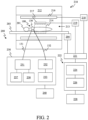
- FIG. 2 shows an ECG system for monitoring ECG pulses from a subject, implemented within magnetic resonance imaging (MRI) system, according to a representative embodiment.
- MRI magnetic resonance imaging
- ECG system 200 is incorporated with representative MRI system 210 in order to monitor ECG pulses of a subject 201 during an MRI procedure.
- the MRI system 210 may be any type of MRI system, and the following description of the MRI system 210 is intended to be illustrative and not limiting.
- the MRI system 210 includes a magnet 212 with a bore 213.
- the magnet 212 may be a superconducting cylindrical magnet, for example, although use of different types of magnets is possible, such as a split cylindrical magnet and an open magnet.
- An imaging zone 214 is provided in the bore 213 where the magnetic field generated by operation of the magnet 212 is strong and uniform enough to perform the magnetic resonance imaging.
- the subject 201 is placed on a support 203 and positioned within the bore 213 to be imaged during the MRI procedure.
- the support 203 may be attached to an actuator 204 (optional) configured to move the support 203, so that the subject 201 may be moved through the imaging zone 214. Accordingly, a larger portion of the subject 201 or the entire subject 201 may be imaged.
- the ECG system 200 includes the measurement node set 100, discussed above. Accordingly, the ECG electrodes 118, 128 and 138 respectively corresponding to the measurement nodes 110, 120 and 130 are attached to the skin of the subject 201 in order to perform ECG monitoring during the MRI procedure. Only the measurement node 130 is shown in FIG. 2 for the sake of convenience.
- the common node 140 (not shown) creates a virtual ground, and the measurement node 130 is connected to the common node 140 by the short conductive path 135 in order to provide the common electrical reference to the measurement node 130.
- the other measurement nodes 110 and 120 are likewise connected to the virtual ground provided by the common node 140, as discussed above.
- the common node 140 is also a measurement node, and is connected to the corresponding ECG electrode 148.
- the MRI system 210 includes a set of magnetic field gradient coils 216 configured to acquire magnetic resonance data for spatially encoding magnetic spins within the imaging zone 214.
- a magnetic field gradient coil power supply 218 supplies current to the magnetic field gradient coils 216. The current may be controlled as a function of time, and may be ramped or pulsed, for example. Although two magnetic field gradient coils 216 are shown, it is understood that additional magnetic field gradient coils may be included, e.g., to enable spatially encoding in three orthogonal spatial directions.
- the MRI system 210 further includes RF coil 217 located within the bore 213.
- the RF coil 217 is configured to manipulate orientations of magnetic spins within the imaging zone 214, and to receive RF transmissions from spins also within the imaging zone 214.
- the RF coil 217 may represent dedicated transmit and receive antennas or may contain multiple transmit and receive coil elements.
- the RF coil 217 is shown connected to an RF transceiver 219, which transmits and receives RF signals to and from the RF coil 217 during the MRI procedure. In various configurations, the RF coil 217 and the RF transceiver 219 may be replaced by separate transmit and receive coils and separate transmitters and receivers, for example.
- the actuator 204, the magnetic field gradient coil power supply 218, and the RF transceiver 219 are connected to a hardware interface 221 and a controller 222.
- the controller 222 includes a processor 224, memory 226, and a user interface 228.
- the memory 226 represents one or more non-transitory memories and/or data storage, discussed further below.
- the memory 226 may store pulse sequence instructions, which are executed by the processor 224 for performing the MRI procedure.
- the memory 226 may also include data storage for storing magnetic resonance data and/or reconstructed magnetic resonance images acquired during the MRI procedure.
- the hardware interface 221 enables the controller 222 to interact with, control and/or exchange data with at least the actuator 204, the magnetic field gradient coil power supply 218, and the RF transceiver 219.
- the hardware interface 221 may include one or more of a universal serial bus (USB), IEEE 1394 port, parallel port, IEEE 1284 port, serial port, RS-232 port, IEEE-488 port, Bluetooth connection, wireless local area network connection, TCP/IP connection, Ethernet connection, control voltage interface, MIDI interface, analog input interface, and digital input interface, for example.
- USB universal serial bus
- IEEE 1394 port parallel port
- IEEE 1284 port serial port
- RS-232 port serial port
- IEEE-488 port Bluetooth connection
- wireless local area network connection TCP/IP connection
- Ethernet connection control voltage interface
- MIDI interface digital input interface
- the processor 224 is representative of one or more processing devices and may be implemented by a general-purpose computer, a central processing unit, a computer processor, a microprocessor, a microcontroller, field programmable gate arrays (FPGAs), application specific integrated circuits (ASICs), a state machine, programmable logic device, or combinations thereof, using any combination of hardware, software, firmware, hard-wired logic circuits, or combinations thereof.
- a processor may also refer to a collection of processors within a single computer system or distributed among multiple computer systems, such as in a cloud-based or other multi-site application.
- the memory 226 may be implemented by any number, type and combination of random-access memory (RAM) and read-only memory (ROM), for example, and may store various types of information, such as software algorithms, artificial intelligence (AI) machine learning models, and computer programs, all of which are executable by the processor 224.
- RAM random-access memory
- ROM read-only memory
- the various types of ROM and RAM may include any number, type and combination of non-transitory computer readable storage media, such as a disk drive, flash memory, an electrically programmable read-only memory (EPROM), an electrically erasable and programmable read-only memory
- non-transitory is to be interpreted not as an eternal characteristic of a state, but as a characteristic of a state that will last for a period.
- non-transitory specifically disavows fleeting characteristics such as characteristics of a carrier wave or signal or other forms that exist only transitorily in any place at any time.
- the user interface 228 enables a user or operator to interact with the controller 222, receiving input from the operator to be received by the processor 224 and providing output to the user from the processor 224. That is, the user interface 228 may provide information or data to the operator and/or receive information or data from the operator.
- the display of data or information on a display or a graphical user interface is an example of providing information to the operator.
- the receiving of data through a keyboard, mouse, trackball, touchpad, pointing stick, graphics tablet, joystick, gamepad, webcam, headset, pedals, wired glove, remote control, and accelerometer are all examples of components of the user interface 228 which enable the receiving of information or data from the operator.
- the ECG system 200 further includes an ECG module 230 and an output 240.
- the ECG module 230 includes an optical modulator 231, an optical demodulator 232, and a processor 233.
- the optical modulator 231 is configured to receive a clock signal from a clock 237 and a light signal from a light source 238, to modulate the light signal and the clock signal using any compatible modulation technique, and to output a modulated optical signal with an embedded clock signal to the measurement nodes 110, 120 and 130 via the respective input fiber-optic cables 111, 121 and 131, respectively.
- the light source 238 may be a laser or a light emitting diode (LED), for example.
- the optical modulator 231 may provide a pulse width modulated (PWM) optical signal with an embedded clock signal, which may be embedded via light pulses, for example.
- the optical modulator 231 may provide a frequency modulated or amplitude modulated optical signal with the embedded clock signal.
- the frequencies and/or widths of the light pulses in the PWM optical signal and the embedded clock signal may be adjusted to suit the MRI scanning environment. For example, certain frequencies must be avoided as to not interfere with the MR scanned image.
- a tunable configuration of the ECG module 230 allows all frequencies to be selected or avoided.
- the optical demodulator 232 is configured to receive optical ECG signals from the measurement nodes 110, 120 and 130 via the respective output fiber-optic cables 112, 122 and 132, respectively, and to convert the ECG signals into corresponding electrical signals.
- the processor 233 is configured to execute instructions stored in a non-transitory memory (not shown) for processing the electrical signals to provide a corresponding ECG wave to the output 240.
- the instructions may further cause the processor 233 to define characteristics of the ECG signals, such as the QRS complex, average beat, heart rate variability, RR interval, PR interval, and pulse rate, for example.
- the memory may be one or more non-transitory memories and/or data storage, as described above with reference to the memory 226.
- the processor 233 is representative of one or more processing devices, and may be implemented by a general-purpose computer, a central processing unit, a computer processor, a microprocessor, a microcontroller, FPGAs, ASICs, a state machine, programmable logic device, or combinations thereof, using any combination of hardware, software, firmware, hard-wired logic circuits, or combinations thereof.
- a processor may also refer to a collection of processors within a single computer system or distributed among multiple computer systems, such as in a cloud-based or other multi-site application.
- the output 240 may include any type of visual manifestation of the ECG traces.
- the output 240 may include a display for displaying the ECG wave, such as a computer monitor, a television, a liquid crystal display (LCD), an organic light emitting diode (OLED) display, a flat panel display, a solid-state display, or a cathode ray tube (CRT) display, a touch screen or an electronic whiteboard, for example.
- the output 240 may include a printer, such as a thermal printer or an inkjet printer, for example, for printing the ECG wave.
- ECG wave may be displayed and/or printed together with textual and/or graphical information that classifies and/or interprets the ECG wave.
- the measurement nodes 110, 120 and 130 are physically connected to the ECG module 230 via the input fiber-optic cables 111, 121 and 131 and the output fiber-optic cables 112, 122 and 132, respectively.
- the measurement nodes 110, 120 and 130 may be connected to a transceiver and antenna (not shown) via the input fiber-optic cables 111, 121 and 131 and the output fiber-optic cables 112, 122 and 132, respectively, where the transceiver is configured to communicate wirelessly with the ECG module 230.
- the ECG module 230 would likewise include a transceiver and antenna (not shown) for sending the DC power and clock signals and receiving the ECG signals.
- FIG. 3 is a simplified block diagram showing an illustrative measurement node for monitoring ECG signals from a subject, according to a representative embodiment.
- FIG. 3 shows the measurement node 130 as being representative of all the measurement nodes, for purposes of illustration.
- the measurement node 130 includes a DC power converter 310 and a clock recovery circuit 315, which are connected to the input fiber-optic cable 131.
- the DC power converter 310 is configured to receive the modulated optical signal from the optical modulator 231 of the ECG module 230 via the input fiber-optic cable 131, and to convert the modulated optical signal to a corresponding electrical signal. By converting the modulated optical signal to the electrical signal, the DC power converter 310 recovers DC power embedded within the modulated optical signal. For example, when the modulated optical signal is a PWM optical signal, the magnitude of the DC power is indicated by the frequency and/or widths of the light pulses.
- the DC power converter 310 may be a photovoltaic cell, for example, which converts optical signals directly into electrical signals using photovoltaic effect.
- the clock recovery circuit 315 recovers the embedded clock signal from the modulated optical signal.
- the clock recovery circuit 315 may be an edge detector, phase detector or a frequency detector, for example. The detectors of the clock recovery circuit depend on how the clock is optically encoded, as is known in the art. Recovery of the DC power and the embedded clock signal may be performed in any order or simultaneously.
- the DC power converter 310 outputs the DC power (Vcc) and the clock recovery circuit 315 outputs the recovered clock signal (Clk) to other components of the measurement node 130, discussed below.
- the measurement node 130 is shown connected to the ECG electrode 138, which is attached to the skin of the subject 201, to receive small analog ECG pulses, which may be in the ⁇ V to mV ranges.
- the measurement node 130 provides an analog front end for the ECG electrode 138, including an optional programmable gain amplifier (PGA) 320 (indicated by dashed lines) and an analog-to-digital converter (ADC) 330, as well as an optical converter 340.
- PGA programmable gain amplifier
- ADC analog-to-digital converter
- each of the PGA 320, the ADC 330, and the optical converter 340 receive the DC power (Vcc) from the DC power converter 310 and the recovered clock signal (Clk) from the clock recovery circuit 315. Accordingly, the PGA 320, the ADC 330, and the optical converter 340 are powered without an electrical power source using the DC power (Vcc) and are synchronized with one another using the recovered clock signal (Clk).
- the PGA 320 receives the analog ECG pulses from the ECG electrode 138, which are electrical signals.
- the ADC 330 converts the ECG pulses into digital ECG signals at a predetermined sampling frequency (e.g., 300 Hz).
- the optical converter 340 receives the digital ECG signals and converts them to optical ECG signals.
- the optical converter 340 may be a laser or an LED light source, for example.
- the optical converter 340 outputs the optical ECG signals to the optical demodulator 232 of the ECG module 230 via the output fiber-optic cable 132.
- the grounds of each of the DC power converter 310, the clock recovery circuit 315, the PGA 320, the ADC 330, and the optical converter 340 are connected to the virtual ground (V-gnd) created by the common node 140 via the conductive path 135. Accordingly, the DC power and clock recovery circuit 315, the PGA 320, the ADC 330, and the optical converter 340 are grounded to a common potential, along with the components of the other measurement nodes (e.g., measurement nodes 110, 120), without having to be electrically grounded elsewhere in the ECG system 200.
- the recovered DC power and the virtual grounding of the measurement node 130 eliminate the need for electrical leads connecting the measurement node 130 to an external power source and ground.
Landscapes
- Health & Medical Sciences (AREA)
- Life Sciences & Earth Sciences (AREA)
- Engineering & Computer Science (AREA)
- Physics & Mathematics (AREA)
- Molecular Biology (AREA)
- General Health & Medical Sciences (AREA)
- Biophysics (AREA)
- Biomedical Technology (AREA)
- Heart & Thoracic Surgery (AREA)
- Medical Informatics (AREA)
- Veterinary Medicine (AREA)
- Surgery (AREA)
- Animal Behavior & Ethology (AREA)
- Pathology (AREA)
- Public Health (AREA)
- Computer Networks & Wireless Communication (AREA)
- Cardiology (AREA)
- Power Engineering (AREA)
- Physiology (AREA)
- Electromagnetism (AREA)
- Signal Processing (AREA)
- Measurement And Recording Of Electrical Phenomena And Electrical Characteristics Of The Living Body (AREA)
- Magnetic Resonance Imaging Apparatus (AREA)
Claims (14)
- System (100) zum Erfassen von Elektrokardiogramm (EKG)-Impulsen von einer Person, wobei das System umfasst:einen gemeinsamen Knoten (140), der so konfiguriert ist, dass er eine virtuelle Masse (V-gnd) erzeugt; undeine Vielzahl von Messknoten (110, 120, 130), die mit einer Vielzahl von entsprechenden EKG-Elektroden (118, 128, 138) verbunden werden können, die jeweils an der Person angebracht werden können;wobei die Vielzahl von Messknoten mit der virtuellen Masse am gemeinsamen Knoten über jeweils kurze leitende Pfade (115, 125, 135) verbunden sind;wobei jeder Messknoten der Vielzahl von Messknoten umfasst:einen Analog-Digital-Wandler (ADC, 330), der so konfiguriert ist, dass er ein EKG-Signal von der entsprechenden EKG-Elektrode in ein digitales Signal umwandelt;einen optischen Wandler (340), der so konfiguriert ist, dass er das digitale Signal vom ADC in ein optisches Signal umwandelt und das optische Signal über einen Ausgangslichtwellenleiter (112, 122, 132) ausgibt;einen Gleichstromwandler (310), der so konfiguriert ist, dass er ein moduliertes optisches Signal mit einem eingebetteten Taktsignal über einen Eingangslichtwellenleiter (111, 121, 131) empfängt, um Gleichstrom aus dem modulierten optischen Signal zu gewinnen und den Gleichstrom mindestens dem ADC und dem optischen Wandler zuzuführen; undeine Taktrückgewinnungsschaltung (315), die so konfiguriert ist, dass sie das modulierte optische Signal mit dem eingebetteten Taktsignal über den Eingangslichtwellenleiter empfängt, das eingebettete Taktsignal aus dem modulierten optischen Signal zurückgewinnt und das zurückgewonnene Taktsignal mindestens dem ADC und dem optischen Wandler zur Synchronisation zuführt.
- System nach Anspruch 1, weiter umfassend:
ein EKG-Modul (230), das so konfiguriert ist, dass es das modulierte optische Signal jeweils über die Eingangslichtwellenleiter an die Vielzahl von Messknoten liefert, die optischen Signale jeweils über die Ausgangslichtwellenleiter von der Vielzahl von Messknoten empfängt und die optischen Signale in die EKG-Impulse umwandelt. - System nach einem der Ansprüche 1 oder 2, wobei der gemeinsame Knoten als Messknoten konfiguriert ist, der mit einer entsprechenden EKG-Elektrode verbunden werden kann, die an der Person angebracht werden kann.
- System nach Anspruch 3, wobei die Vielzahl von Messknoten einen Messknoten für den linken Arm (LA), einen Messknoten für den rechten Arm (RA) und einen Messknoten für das linke Bein (LL) umfasst; und
wobei der gemeinsame Knoten einen Messknoten für das rechte Bein (RL) umfasst. - System nach einem der Ansprüche 1-4, wobei der Gleichstromwandler jedes Messknotens der Vielzahl von Messknoten eine Photovoltaikzelle umfasst.
- System nach einem der Ansprüche 1-5, wobei jeder Messknoten der Vielzahl von Messknoten weiter umfasst:
einen programmierbaren Verstärker (PGA, 320), der mit einem Eingang des ADC verbunden und so konfiguriert ist, dass er das EKG-Signal verstärkt. - System nach einem der Ansprüche 2-6, weiter umfassend:
einen Monitor, der so konfiguriert ist, dass er die von dem EKG-Modul ausgegebenen EKG-Impulse anzeigt. - System nach einem der Ansprüche 1-7, wobei die Person in einer Magnetresonanztomographie (MRI)-Röhre positioniert ist, während die EKG-Impulse erfasst werden.
- System nach einem der Ansprüche 1-8, wobei das modulierte optische Signal ein pulsbreitenmoduliertes (PWM) optisches Signal umfasst.
- System nach einem der Ansprüche 1-9, wobei das modulierte optische Signal ein frequenzmoduliertes oder amplitudenmoduliertes optisches Signal umfasst.
- System nach einem der Ansprüche 1-10, wobei jeder Messknoten der Vielzahl von Messknoten umfasst:ein analoges Frontend, das den Analog-Digital-Wandler (ADC) des entsprechenden Messknotens umfasst und so konfiguriert ist, dass es ein EKG-Signal von der entsprechenden EKG-Elektrode empfängt und verarbeitet;wobei der Gleichstromwandler so konfiguriert ist, dass er den Gleichstrom dem analogen Frontend zuführt; undwobei die Taktrückgewinnungsschaltung so konfiguriert ist, dass sie das zurückgewonnene Taktsignal dem analogen Frontend zuführt.
- System nach einem der Ansprüche 1-11, wobei jeder Messknoten der Vielzahl von Messknoten so konfiguriert ist, dass er an einer oberen Fläche der entsprechenden EKG-Elektrode einrastet oder anklemmt.
- System nach einem der Ansprüche 1-11, wobei jeder Messknoten der Vielzahl von Messknoten weiter die entsprechende EKG-Elektrode umfasst, die physisch in den Messknoten integriert ist.
- Messknoten (110, 120, 130), der mit einer Elektrokardiogramm (EKG)-Elektrode (118, 128, 138) verbunden werden kann, die an einem Körper einer Person angebracht werden kann, um EKG-Impulse von der Person zu messen, wobei der Messknoten umfasst:einen Analog-Digital-Wandler (ADC, 330), der so konfiguriert ist, dass er ein EKG-Signal von der EKG-Elektrode in ein digitales Signal umwandelt;einen optischen Wandler (340), der so konfiguriert ist, dass er das digitale Signal vom ADC in ein optisches Signal umwandelt und das optische Signal über einen Ausgangslichtwellenleiter (112, 122, 132) an einen EKG-Monitor ausgibt;einen Gleichstromwandler (310), der so konfiguriert ist, dass er ein moduliertes optisches Signal vom EKG-Monitor mit einem eingebetteten Taktsignal über einen Eingangslichtwellenleiter (111, 121, 131) empfängt, um Gleichstrom aus dem modulierten optischen Signal zu gewinnen und den Gleichstrom mindestens dem ADC und dem optischen Wandler zuzuführen; undeine Taktrückgewinnungsschaltung (315), die so konfiguriert ist, dass sie das modulierte optische Signal mit dem eingebetteten Taktsignal über den Eingangslichtwellenleiter empfängt, das eingebettete Taktsignal aus dem modulierten optischen Signal zurückgewinnt und das zurückgewonnene Taktsignal mindestens dem ADC und dem optischen Wandler zur Synchronisation zuführt,wobei der ADC, der optische Wandler, der Gleichstromleistungswandler und die Taktrückgewinnungsschaltung mit einer virtuellen Masse (V-gnd) verbunden sind, die durch einen gemeinsamen Knoten (140) erzeugt wird, der über einen kurzen leitenden Pfad (115, 125, 135) zwischen dem Messknoten und dem gemeinsamen Knoten am Körper der Person angebracht werden kann.
Applications Claiming Priority (2)
| Application Number | Priority Date | Filing Date | Title |
|---|---|---|---|
| US202263305800P | 2022-02-02 | 2022-02-02 | |
| PCT/EP2023/052104 WO2023148112A1 (en) | 2022-02-02 | 2023-01-29 | System for monitoring electrocardiogram pulses using virtual ground |
Publications (2)
| Publication Number | Publication Date |
|---|---|
| EP4472489A1 EP4472489A1 (de) | 2024-12-11 |
| EP4472489B1 true EP4472489B1 (de) | 2025-05-28 |
Family
ID=85150430
Family Applications (1)
| Application Number | Title | Priority Date | Filing Date |
|---|---|---|---|
| EP23702557.2A Active EP4472489B1 (de) | 2022-02-02 | 2023-01-29 | System zur überwachung von elektrokardiogrammimpulsen mittels virtueller masse |
Country Status (5)
| Country | Link |
|---|---|
| US (1) | US20250169695A1 (de) |
| EP (1) | EP4472489B1 (de) |
| JP (1) | JP2025505405A (de) |
| CN (1) | CN118647306A (de) |
| WO (1) | WO2023148112A1 (de) |
Families Citing this family (2)
| Publication number | Priority date | Publication date | Assignee | Title |
|---|---|---|---|---|
| WO2024056434A1 (en) * | 2022-09-12 | 2024-03-21 | Koninklijke Philips N.V. | Optically-powered ecg measurement nodes and ecg sensing networks |
| CN119894434A (zh) * | 2022-09-14 | 2025-04-25 | 皇家飞利浦有限公司 | 电压转频率心电图测量节点 |
Family Cites Families (13)
| Publication number | Priority date | Publication date | Assignee | Title |
|---|---|---|---|---|
| US6117076A (en) * | 1998-09-21 | 2000-09-12 | Belmont Instruments Corporation | Patient monitoring system and method |
| AU1241201A (en) * | 1999-10-27 | 2001-05-08 | Physiometrix, Inc. | Low cost high performance patient interface for electroencephalograph signals |
| US20050107681A1 (en) * | 2003-07-23 | 2005-05-19 | Griffiths David M. | Wireless patient monitoring device for magnetic resonance imaging |
| JP2007222475A (ja) * | 2006-02-24 | 2007-09-06 | Toshiba Corp | 心電計測装置及びmri撮像システム |
| WO2008061010A1 (en) * | 2006-11-10 | 2008-05-22 | Draeger Medical Systems, Inc. | An ecg system for use in ecg signal measurement of intra-cardiac ecg using a catheter |
| KR101440458B1 (ko) * | 2013-03-06 | 2014-09-18 | 한국표준과학연구원 | 뇌자도 및 뇌전도, 또는 심자도 및 심전도 검출을 위한 다채널 신호 검출 시스템 |
| KR102400106B1 (ko) * | 2014-11-17 | 2022-05-19 | 삼성전자주식회사 | 심전도 센서 칩, 시스템 온 칩과, 웨어러블 기기 |
| US9625939B2 (en) * | 2015-08-20 | 2017-04-18 | International Business Machines Corporation | Clock forwarding over optics |
| US10063369B1 (en) * | 2015-12-16 | 2018-08-28 | Verily Life Sciences Llc | Time synchronization of multi-modality measurements |
| EP3484349B1 (de) * | 2016-07-15 | 2023-05-31 | Nia Therapeutics, Inc. | Neuromodulationsvorrichtung |
| DE102016222305A1 (de) * | 2016-11-14 | 2018-05-17 | Siemens Healthcare Gmbh | EKG-Elektrode und Verfahren zum Erfassen eines EKG-Messsignals |
| US10313026B2 (en) * | 2017-06-27 | 2019-06-04 | Rolls-Royce North American Technologies, Inc. | Power and communications over fiber optic cabling |
| EP3771404A1 (de) * | 2019-07-31 | 2021-02-03 | Koninklijke Philips N.V. | Kalibrierung eines sensors |
-
2023
- 2023-01-29 WO PCT/EP2023/052104 patent/WO2023148112A1/en not_active Ceased
- 2023-01-29 EP EP23702557.2A patent/EP4472489B1/de active Active
- 2023-01-29 CN CN202380019886.1A patent/CN118647306A/zh active Pending
- 2023-01-29 US US18/834,268 patent/US20250169695A1/en active Pending
- 2023-01-29 JP JP2024544628A patent/JP2025505405A/ja active Pending
Also Published As
| Publication number | Publication date |
|---|---|
| US20250169695A1 (en) | 2025-05-29 |
| EP4472489A1 (de) | 2024-12-11 |
| CN118647306A (zh) | 2024-09-13 |
| WO2023148112A1 (en) | 2023-08-10 |
| JP2025505405A (ja) | 2025-02-26 |
Similar Documents
| Publication | Publication Date | Title |
|---|---|---|
| EP4472489B1 (de) | System zur überwachung von elektrokardiogrammimpulsen mittels virtueller masse | |
| EP2854630B1 (de) | Reduktion von mri-interferenzen aus einem elektrokardiogramm anhand von elektrodeninformationen | |
| US20100191095A1 (en) | Process, device and system for reducing the artifacts that affect electrophysiological signals and that are due to electromagnetic fields | |
| US11850033B2 (en) | RF coil with integrated vital signs detector | |
| US20180055406A1 (en) | Electrophysiological Measurement and Stimulation within MRI Bore | |
| US8659297B2 (en) | Reducing noise in magnetic resonance imaging using conductive loops | |
| KR101440458B1 (ko) | 뇌자도 및 뇌전도, 또는 심자도 및 심전도 검출을 위한 다채널 신호 검출 시스템 | |
| US20250366755A1 (en) | Voltage-to-frquency electrocariogram measurement node | |
| CN104799858A (zh) | 用于磁共振系统的心电呼吸外周门控系统 | |
| JP2025505405A5 (de) | ||
| WO2018183982A1 (en) | Systems and methods for controlling imaging artifacts using an array of sensor data | |
| CN111067523A (zh) | 门控装置及其控制方法、装置、医疗设备系统 | |
| CN208384094U (zh) | 磁共振线圈组件 | |
| CN219594618U (zh) | 构成为结合磁共振设备使用的心电图设备和磁共振设备 | |
| EP4500207B1 (de) | Magnetresonanz-empfängerspulenanordnung mit sensorknoten | |
| WO2024056434A1 (en) | Optically-powered ecg measurement nodes and ecg sensing networks | |
| US11918366B2 (en) | Electrocardiogram device for use in combination with a magnetic resonance device | |
| JP2008516693A (ja) | Mri処置の間の、電子生理的信号の緩衝のための方法と装置 | |
| WO2006076244A1 (en) | Method of producing a synthesized bipolar ecg waveform from a scalar ecg waveform | |
| HK1109456B (en) | Method and apparatus for buffering electrophysiological signals during an mri procedure |
Legal Events
| Date | Code | Title | Description |
|---|---|---|---|
| STAA | Information on the status of an ep patent application or granted ep patent |
Free format text: STATUS: UNKNOWN |
|
| STAA | Information on the status of an ep patent application or granted ep patent |
Free format text: STATUS: THE INTERNATIONAL PUBLICATION HAS BEEN MADE |
|
| PUAI | Public reference made under article 153(3) epc to a published international application that has entered the european phase |
Free format text: ORIGINAL CODE: 0009012 |
|
| STAA | Information on the status of an ep patent application or granted ep patent |
Free format text: STATUS: REQUEST FOR EXAMINATION WAS MADE |
|
| 17P | Request for examination filed |
Effective date: 20240902 |
|
| AK | Designated contracting states |
Kind code of ref document: A1 Designated state(s): AL AT BE BG CH CY CZ DE DK EE ES FI FR GB GR HR HU IE IS IT LI LT LU LV MC ME MK MT NL NO PL PT RO RS SE SI SK SM TR |
|
| GRAP | Despatch of communication of intention to grant a patent |
Free format text: ORIGINAL CODE: EPIDOSNIGR1 |
|
| STAA | Information on the status of an ep patent application or granted ep patent |
Free format text: STATUS: GRANT OF PATENT IS INTENDED |
|
| DAV | Request for validation of the european patent (deleted) | ||
| DAX | Request for extension of the european patent (deleted) | ||
| INTG | Intention to grant announced |
Effective date: 20250115 |
|
| RIN1 | Information on inventor provided before grant (corrected) |
Inventor name: APPLETON, BRUCE GEOFFREY Inventor name: REDDER, PAUL FRANZ Inventor name: BROWN, RICHARD EARL |
|
| GRAS | Grant fee paid |
Free format text: ORIGINAL CODE: EPIDOSNIGR3 |
|
| GRAA | (expected) grant |
Free format text: ORIGINAL CODE: 0009210 |
|
| STAA | Information on the status of an ep patent application or granted ep patent |
Free format text: STATUS: THE PATENT HAS BEEN GRANTED |
|
| AK | Designated contracting states |
Kind code of ref document: B1 Designated state(s): AL AT BE BG CH CY CZ DE DK EE ES FI FR GB GR HR HU IE IS IT LI LT LU LV MC ME MK MT NL NO PL PT RO RS SE SI SK SM TR |
|
| REG | Reference to a national code |
Ref country code: GB Ref legal event code: FG4D |
|
| REG | Reference to a national code |
Ref country code: CH Ref legal event code: EP |
|
| REG | Reference to a national code |
Ref country code: IE Ref legal event code: FG4D Ref country code: DE Ref legal event code: R096 Ref document number: 602023003716 Country of ref document: DE |
|
| REG | Reference to a national code |
Ref country code: DE Ref legal event code: R084 Ref document number: 602023003716 Country of ref document: DE |
|
| REG | Reference to a national code |
Ref country code: NL Ref legal event code: MP Effective date: 20250528 |
|
| PG25 | Lapsed in a contracting state [announced via postgrant information from national office to epo] |
Ref country code: FI Free format text: LAPSE BECAUSE OF FAILURE TO SUBMIT A TRANSLATION OF THE DESCRIPTION OR TO PAY THE FEE WITHIN THE PRESCRIBED TIME-LIMIT Effective date: 20250528 Ref country code: ES Free format text: LAPSE BECAUSE OF FAILURE TO SUBMIT A TRANSLATION OF THE DESCRIPTION OR TO PAY THE FEE WITHIN THE PRESCRIBED TIME-LIMIT Effective date: 20250528 |
|
| REG | Reference to a national code |
Ref country code: LT Ref legal event code: MG9D |
|
| PG25 | Lapsed in a contracting state [announced via postgrant information from national office to epo] |
Ref country code: GR Free format text: LAPSE BECAUSE OF FAILURE TO SUBMIT A TRANSLATION OF THE DESCRIPTION OR TO PAY THE FEE WITHIN THE PRESCRIBED TIME-LIMIT Effective date: 20250829 Ref country code: NO Free format text: LAPSE BECAUSE OF FAILURE TO SUBMIT A TRANSLATION OF THE DESCRIPTION OR TO PAY THE FEE WITHIN THE PRESCRIBED TIME-LIMIT Effective date: 20250828 |
|
| PG25 | Lapsed in a contracting state [announced via postgrant information from national office to epo] |
Ref country code: NL Free format text: LAPSE BECAUSE OF FAILURE TO SUBMIT A TRANSLATION OF THE DESCRIPTION OR TO PAY THE FEE WITHIN THE PRESCRIBED TIME-LIMIT Effective date: 20250528 Ref country code: PL Free format text: LAPSE BECAUSE OF FAILURE TO SUBMIT A TRANSLATION OF THE DESCRIPTION OR TO PAY THE FEE WITHIN THE PRESCRIBED TIME-LIMIT Effective date: 20250528 |
|
| PG25 | Lapsed in a contracting state [announced via postgrant information from national office to epo] |
Ref country code: BG Free format text: LAPSE BECAUSE OF FAILURE TO SUBMIT A TRANSLATION OF THE DESCRIPTION OR TO PAY THE FEE WITHIN THE PRESCRIBED TIME-LIMIT Effective date: 20250528 |
|
| PG25 | Lapsed in a contracting state [announced via postgrant information from national office to epo] |
Ref country code: HR Free format text: LAPSE BECAUSE OF FAILURE TO SUBMIT A TRANSLATION OF THE DESCRIPTION OR TO PAY THE FEE WITHIN THE PRESCRIBED TIME-LIMIT Effective date: 20250528 |
|
| PG25 | Lapsed in a contracting state [announced via postgrant information from national office to epo] |
Ref country code: RS Free format text: LAPSE BECAUSE OF FAILURE TO SUBMIT A TRANSLATION OF THE DESCRIPTION OR TO PAY THE FEE WITHIN THE PRESCRIBED TIME-LIMIT Effective date: 20250828 |
|
| PG25 | Lapsed in a contracting state [announced via postgrant information from national office to epo] |
Ref country code: IS Free format text: LAPSE BECAUSE OF FAILURE TO SUBMIT A TRANSLATION OF THE DESCRIPTION OR TO PAY THE FEE WITHIN THE PRESCRIBED TIME-LIMIT Effective date: 20250928 |
|
| PG25 | Lapsed in a contracting state [announced via postgrant information from national office to epo] |
Ref country code: LV Free format text: LAPSE BECAUSE OF FAILURE TO SUBMIT A TRANSLATION OF THE DESCRIPTION OR TO PAY THE FEE WITHIN THE PRESCRIBED TIME-LIMIT Effective date: 20250528 |
|
| REG | Reference to a national code |
Ref country code: AT Ref legal event code: MK05 Ref document number: 1798145 Country of ref document: AT Kind code of ref document: T Effective date: 20250528 |
|
| REG | Reference to a national code |
Ref country code: GB Ref legal event code: 746 Effective date: 20251114 |
|
| PG25 | Lapsed in a contracting state [announced via postgrant information from national office to epo] |
Ref country code: DK Free format text: LAPSE BECAUSE OF FAILURE TO SUBMIT A TRANSLATION OF THE DESCRIPTION OR TO PAY THE FEE WITHIN THE PRESCRIBED TIME-LIMIT Effective date: 20250528 Ref country code: SM Free format text: LAPSE BECAUSE OF FAILURE TO SUBMIT A TRANSLATION OF THE DESCRIPTION OR TO PAY THE FEE WITHIN THE PRESCRIBED TIME-LIMIT Effective date: 20250528 Ref country code: AT Free format text: LAPSE BECAUSE OF FAILURE TO SUBMIT A TRANSLATION OF THE DESCRIPTION OR TO PAY THE FEE WITHIN THE PRESCRIBED TIME-LIMIT Effective date: 20250528 |
|
| PG25 | Lapsed in a contracting state [announced via postgrant information from national office to epo] |
Ref country code: CZ Free format text: LAPSE BECAUSE OF FAILURE TO SUBMIT A TRANSLATION OF THE DESCRIPTION OR TO PAY THE FEE WITHIN THE PRESCRIBED TIME-LIMIT Effective date: 20250528 |
|
| PG25 | Lapsed in a contracting state [announced via postgrant information from national office to epo] |
Ref country code: EE Free format text: LAPSE BECAUSE OF FAILURE TO SUBMIT A TRANSLATION OF THE DESCRIPTION OR TO PAY THE FEE WITHIN THE PRESCRIBED TIME-LIMIT Effective date: 20250528 |
|
| PG25 | Lapsed in a contracting state [announced via postgrant information from national office to epo] |
Ref country code: SK Free format text: LAPSE BECAUSE OF FAILURE TO SUBMIT A TRANSLATION OF THE DESCRIPTION OR TO PAY THE FEE WITHIN THE PRESCRIBED TIME-LIMIT Effective date: 20250528 |
|
| PG25 | Lapsed in a contracting state [announced via postgrant information from national office to epo] |
Ref country code: IT Free format text: LAPSE BECAUSE OF FAILURE TO SUBMIT A TRANSLATION OF THE DESCRIPTION OR TO PAY THE FEE WITHIN THE PRESCRIBED TIME-LIMIT Effective date: 20250528 |
|
| REG | Reference to a national code |
Ref country code: DE Ref legal event code: R097 Ref document number: 602023003716 Country of ref document: DE |
|
| PLBE | No opposition filed within time limit |
Free format text: ORIGINAL CODE: 0009261 |
|
| STAA | Information on the status of an ep patent application or granted ep patent |
Free format text: STATUS: NO OPPOSITION FILED WITHIN TIME LIMIT |
|
| REG | Reference to a national code |
Ref country code: CH Ref legal event code: L10 Free format text: ST27 STATUS EVENT CODE: U-0-0-L10-L00 (AS PROVIDED BY THE NATIONAL OFFICE) Effective date: 20260409 |
|
| PGFP | Annual fee paid to national office [announced via postgrant information from national office to epo] |
Ref country code: DE Payment date: 20260127 Year of fee payment: 4 |