EP4472294A2 - Effizienter rundfunkkanal in strahlgeformten systemen für new radio - Google Patents
Effizienter rundfunkkanal in strahlgeformten systemen für new radio Download PDFInfo
- Publication number
- EP4472294A2 EP4472294A2 EP24207029.0A EP24207029A EP4472294A2 EP 4472294 A2 EP4472294 A2 EP 4472294A2 EP 24207029 A EP24207029 A EP 24207029A EP 4472294 A2 EP4472294 A2 EP 4472294A2
- Authority
- EP
- European Patent Office
- Prior art keywords
- bits
- pbch
- mib
- trp
- wtru
- Prior art date
- Legal status (The legal status is an assumption and is not a legal conclusion. Google has not performed a legal analysis and makes no representation as to the accuracy of the status listed.)
- Pending
Links
Images









Classifications
-
- H—ELECTRICITY
- H04—ELECTRIC COMMUNICATION TECHNIQUE
- H04L—TRANSMISSION OF DIGITAL INFORMATION, e.g. TELEGRAPHIC COMMUNICATION
- H04L1/00—Arrangements for detecting or preventing errors in the information received
- H04L1/004—Arrangements for detecting or preventing errors in the information received by using forward error control
- H04L1/0056—Systems characterized by the type of code used
- H04L1/0067—Rate matching
-
- H—ELECTRICITY
- H03—ELECTRONIC CIRCUITRY
- H03M—CODING; DECODING; CODE CONVERSION IN GENERAL
- H03M13/00—Coding, decoding or code conversion, for error detection or error correction; Coding theory basic assumptions; Coding bounds; Error probability evaluation methods; Channel models; Simulation or testing of codes
- H03M13/03—Error detection or forward error correction by redundancy in data representation, i.e. code words containing more digits than the source words
- H03M13/05—Error detection or forward error correction by redundancy in data representation, i.e. code words containing more digits than the source words using block codes, i.e. a predetermined number of check bits joined to a predetermined number of information bits
- H03M13/09—Error detection only, e.g. using cyclic redundancy check [CRC] codes or single parity bit
-
- H—ELECTRICITY
- H03—ELECTRONIC CIRCUITRY
- H03M—CODING; DECODING; CODE CONVERSION IN GENERAL
- H03M13/00—Coding, decoding or code conversion, for error detection or error correction; Coding theory basic assumptions; Coding bounds; Error probability evaluation methods; Channel models; Simulation or testing of codes
- H03M13/03—Error detection or forward error correction by redundancy in data representation, i.e. code words containing more digits than the source words
- H03M13/05—Error detection or forward error correction by redundancy in data representation, i.e. code words containing more digits than the source words using block codes, i.e. a predetermined number of check bits joined to a predetermined number of information bits
- H03M13/13—Linear codes
-
- H—ELECTRICITY
- H04—ELECTRIC COMMUNICATION TECHNIQUE
- H04B—TRANSMISSION
- H04B7/00—Radio transmission systems, i.e. using radiation field
- H04B7/02—Diversity systems; Multi-antenna system, i.e. transmission or reception using multiple antennas
- H04B7/04—Diversity systems; Multi-antenna system, i.e. transmission or reception using multiple antennas using two or more spaced independent antennas
- H04B7/06—Diversity systems; Multi-antenna system, i.e. transmission or reception using multiple antennas using two or more spaced independent antennas at the transmitting station
- H04B7/0613—Diversity systems; Multi-antenna system, i.e. transmission or reception using multiple antennas using two or more spaced independent antennas at the transmitting station using simultaneous transmission
- H04B7/0615—Diversity systems; Multi-antenna system, i.e. transmission or reception using multiple antennas using two or more spaced independent antennas at the transmitting station using simultaneous transmission of weighted versions of same signal
- H04B7/0617—Diversity systems; Multi-antenna system, i.e. transmission or reception using multiple antennas using two or more spaced independent antennas at the transmitting station using simultaneous transmission of weighted versions of same signal for beam forming
-
- H—ELECTRICITY
- H04—ELECTRIC COMMUNICATION TECHNIQUE
- H04B—TRANSMISSION
- H04B7/00—Radio transmission systems, i.e. using radiation field
- H04B7/02—Diversity systems; Multi-antenna system, i.e. transmission or reception using multiple antennas
- H04B7/04—Diversity systems; Multi-antenna system, i.e. transmission or reception using multiple antennas using two or more spaced independent antennas
- H04B7/06—Diversity systems; Multi-antenna system, i.e. transmission or reception using multiple antennas using two or more spaced independent antennas at the transmitting station
- H04B7/0613—Diversity systems; Multi-antenna system, i.e. transmission or reception using multiple antennas using two or more spaced independent antennas at the transmitting station using simultaneous transmission
- H04B7/0615—Diversity systems; Multi-antenna system, i.e. transmission or reception using multiple antennas using two or more spaced independent antennas at the transmitting station using simultaneous transmission of weighted versions of same signal
- H04B7/0619—Diversity systems; Multi-antenna system, i.e. transmission or reception using multiple antennas using two or more spaced independent antennas at the transmitting station using simultaneous transmission of weighted versions of same signal using feedback from receiving side
- H04B7/0621—Feedback content
- H04B7/0623—Auxiliary parameters, e.g. power control [PCB] or not acknowledged commands [NACK], used as feedback information
-
- H—ELECTRICITY
- H04—ELECTRIC COMMUNICATION TECHNIQUE
- H04H—BROADCAST COMMUNICATION
- H04H20/00—Arrangements for broadcast or for distribution combined with broadcast
- H04H20/65—Arrangements characterised by transmission systems for broadcast
-
- H—ELECTRICITY
- H04—ELECTRIC COMMUNICATION TECHNIQUE
- H04L—TRANSMISSION OF DIGITAL INFORMATION, e.g. TELEGRAPHIC COMMUNICATION
- H04L1/00—Arrangements for detecting or preventing errors in the information received
- H04L1/004—Arrangements for detecting or preventing errors in the information received by using forward error control
-
- H—ELECTRICITY
- H04—ELECTRIC COMMUNICATION TECHNIQUE
- H04L—TRANSMISSION OF DIGITAL INFORMATION, e.g. TELEGRAPHIC COMMUNICATION
- H04L1/00—Arrangements for detecting or preventing errors in the information received
- H04L1/004—Arrangements for detecting or preventing errors in the information received by using forward error control
- H04L1/0056—Systems characterized by the type of code used
- H04L1/0057—Block codes
-
- H—ELECTRICITY
- H04—ELECTRIC COMMUNICATION TECHNIQUE
- H04L—TRANSMISSION OF DIGITAL INFORMATION, e.g. TELEGRAPHIC COMMUNICATION
- H04L1/00—Arrangements for detecting or preventing errors in the information received
- H04L1/004—Arrangements for detecting or preventing errors in the information received by using forward error control
- H04L1/0056—Systems characterized by the type of code used
- H04L1/0061—Error detection codes
-
- H—ELECTRICITY
- H04—ELECTRIC COMMUNICATION TECHNIQUE
- H04L—TRANSMISSION OF DIGITAL INFORMATION, e.g. TELEGRAPHIC COMMUNICATION
- H04L1/00—Arrangements for detecting or preventing errors in the information received
- H04L1/004—Arrangements for detecting or preventing errors in the information received by using forward error control
- H04L1/0056—Systems characterized by the type of code used
- H04L1/007—Unequal error protection
-
- H—ELECTRICITY
- H04—ELECTRIC COMMUNICATION TECHNIQUE
- H04L—TRANSMISSION OF DIGITAL INFORMATION, e.g. TELEGRAPHIC COMMUNICATION
- H04L1/00—Arrangements for detecting or preventing errors in the information received
- H04L1/004—Arrangements for detecting or preventing errors in the information received by using forward error control
- H04L1/0072—Error control for data other than payload data, e.g. control data
-
- H—ELECTRICITY
- H04—ELECTRIC COMMUNICATION TECHNIQUE
- H04W—WIRELESS COMMUNICATION NETWORKS
- H04W48/00—Access restriction; Network selection; Access point selection
- H04W48/08—Access restriction or access information delivery, e.g. discovery data delivery
- H04W48/10—Access restriction or access information delivery, e.g. discovery data delivery using broadcasted information
-
- H—ELECTRICITY
- H04—ELECTRIC COMMUNICATION TECHNIQUE
- H04W—WIRELESS COMMUNICATION NETWORKS
- H04W74/00—Wireless channel access
- H04W74/08—Non-scheduled access, e.g. ALOHA
- H04W74/0833—Random access procedures, e.g. with 4-step access
Definitions
- NR Fifth Generation
- eMBB Enhanced Mobile Broadband
- mMTC Massive Machine Type Communications
- URLLC Ultra Reliable and Low latency Communications
- Embodiments may include reducing beam sweep overhead and energy/power savings for transmission of the PBCH.
- Embodiments may include efficiently transmitting system information using the PBCH transmissions.
- Embodiments may include enhancing PBCH performance since information bits carried by PBCH is important.
- Embodiments may include a method of improving the efficiency of physical broadcast channel (PBCH) transmission in a wireless system.
- the method may include: determining a PBCH beam hopping pattern and transmitting the PBCH based on the PBCH beam hopping pattern.
- the method may also include: determining a direction distribution pattern of wireless transmit receive units (WTRU); adjusting the PBCH beam hopping pattern based on the direction distribution pattern; and adjusting the PBCH transmission with a different beam sweeping frequency based on the direction distribution pattern.
- WTRU wireless transmit receive units
- the TRP may generate a concatenated master information block (MIB) transport block that includes information bits associated with system bandwidth information, timing information, system frame number (SFN), a beam sweeping configuration, and a control resource set (CORESET).
- MIB master information block
- SFN system frame number
- CORESET control resource set
- the TRP may then attach at least 16 cyclic redundancy check (CRC) bits to the concatenated MIB, wherein the at least 16 CRC bits include bits for data detection and error correction.
- CRC cyclic redundancy check
- the TRP may then prioritize the concatenated MIB and the at least 16 CRC bits based on content associated with the concatenated MIB and the at least 16 CRC bits.
- the base station 114a may include three transceivers, i.e., one for each sector of the cell.
- the base station 114a may employ multiple-input multiple output (MIMO) technology and may utilize multiple transceivers for each sector of the cell.
- MIMO multiple-input multiple output
- beamforming may be used to transmit and/or receive signals in desired spatial directions.
- the communications system 100 may be a multiple access system and may employ one or more channel access schemes, such as CDMA, TDMA, FDMA, OFDMA, SC-FDMA, and the like.
- the base station 114a in the RAN 104 and the WTRUs 102a, 102b, 102c may implement a radio technology such as Universal Mobile Telecommunications System (UMTS) Terrestrial Radio Access (UTRA), which may establish the air interface 116 using wideband CDMA (WCDMA).
- WCDMA may include communication protocols such as High-Speed Packet Access (HSPA) and/or Evolved HSPA (HSPA+).
- HSPA may include High-Speed Downlink (DL) Packet Access (HSDPA) and/or High-Speed Uplink (UL) Packet Access (HSUPA).
- the base station 114a and the WTRUs 102a, 102b, 102c may implement a radio technology such as Evolved UMTS Terrestrial Radio Access (E-UTRA), which may establish the air interface 116 using Long Term Evolution (LTE) and/or LTE-Advanced (LTE-A) and/or LTE-Advanced Pro (LTE-A Pro).
- E-UTRA Evolved UMTS Terrestrial Radio Access
- LTE Long Term Evolution
- LTE-A LTE-Advanced
- LTE-A Pro LTE-Advanced Pro
- the base station 114a and the WTRUs 102a, 102b, 102c may implement a radio technology such as NR Radio Access, which may establish the air interface 116 using NR.
- a radio technology such as NR Radio Access
- the base station 114a and the WTRUs 102a, 102b, 102c may implement multiple radio access technologies.
- the base station 114a and the WTRUs 102a, 102b, 102c may implement LTE radio access and NR radio access together, for instance using dual connectivity (DC) principles.
- DC dual connectivity
- the air interface utilized by WTRUs 102a, 102b, 102c may be characterized by multiple types of radio access technologies and/or transmissions sent to/from multiple types of base stations (e.g., an eNB and a gNB).
- the base station 114a and the WTRUs 102a, 102b, 102c may implement radio technologies such as IEEE 802.11 (i.e., Wireless Fidelity (WiFi), IEEE 802.16 (i.e., Worldwide Interoperability for Microwave Access (WiMAX)), CDMA2000, CDMA2000 1X, CDMA2000 EV-DO, Interim Standard 2000 (IS-2000), Interim Standard 95 (IS-95), Interim Standard 856 (IS-856), Global System for Mobile communications (GSM), Enhanced Data rates for GSM Evolution (EDGE), GSM EDGE (GERAN), and the like.
- IEEE 802.11 i.e., Wireless Fidelity (WiFi)
- IEEE 802.16 i.e., Worldwide Interoperability for Microwave Access (WiMAX)
- CDMA2000, CDMA2000 1X, CDMA2000 EV-DO Code Division Multiple Access 2000
- IS-95 Interim Standard 95
- IS-856 Interim Standard 856
- GSM Global System for
- the base station 114b in FIG. 1A may be a wireless router, Home Node B, Home eNode B, or access point, for example, and may utilize any suitable RAT for facilitating wireless connectivity in a localized area, such as a place of business, a home, a vehicle, a campus, an industrial facility, an air corridor (e.g., for use by drones), a roadway, and the like.
- the base station 114b and the WTRUs 102c, 102d may implement a radio technology such as IEEE 802.11 to establish a wireless local area network (WLAN).
- WLAN wireless local area network
- the base station 114b and the WTRUs 102c, 102d may implement a radio technology such as IEEE 802.15 to establish a wireless personal area network (WPAN).
- the base station 114b and the WTRUs 102c, 102d may utilize a cellular-based RAT (e.g., WCDMA, CDMA2000, GSM, LTE, LTE-A, LTE-A Pro, NR etc.) to establish a picocell or femtocell.
- the base station 114b may have a direct connection to the Internet 110.
- the base station 114b may not be required to access the Internet 110 via the CN 106.
- the RAN 104 may be in communication with the CN 106, which may be any type of network configured to provide voice, data, applications, and/or voice over internet protocol (VoIP) services to one or more of the WTRUs 102a, 102b, 102c, 102d.
- the data may have varying quality of service (QoS) requirements, such as differing throughput requirements, latency requirements, error tolerance requirements, reliability requirements, data throughput requirements, mobility requirements, and the like.
- QoS quality of service
- the CN 106 may provide call control, billing services, mobile location-based services, pre-paid calling, Internet connectivity, video distribution, etc., and/or perform high-level security functions, such as user authentication.
- the RAN 104 and/or the CN 106 may be in direct or indirect communication with other RANs that employ the same RAT as the RAN 104 or a different RAT.
- the CN 106 may also be in communication with another RAN (not shown) employing a GSM, UMTS, CDMA 2000, WiMAX, E-UTRA, or WiFi radio technology.
- the CN 106 may also serve as a gateway for the WTRUs 102a, 102b, 102c, 102d to access the PSTN 108, the Internet 110, and/or the other networks 112.
- the PSTN 108 may include circuit-switched telephone networks that provide plain old telephone service (POTS).
- POTS plain old telephone service
- the Internet 110 may include a global system of interconnected computer networks and devices that use common communication protocols, such as the transmission control protocol (TCP), user datagram protocol (UDP) and/or the internet protocol (IP) in the TCP/IP internet protocol suite.
- the networks 112 may include wired and/or wireless communications networks owned and/or operated by other service providers.
- the networks 112 may include another CN connected to one or more RANs, which may employ the same RAT as the RAN 104 or a different RAT.
- the WTRUs 102a, 102b, 102c, 102d in the communications system 100 may include multi-mode capabilities (e.g., the WTRUs 102a, 102b, 102c, 102d may include multiple transceivers for communicating with different wireless networks over different wireless links).
- the WTRU 102c shown in FIG. 1A may be configured to communicate with the base station 114a, which may employ a cellular-based radio technology, and with the base station 114b, which may employ an IEEE 802 radio technology.
- FIG. 1B is a system diagram illustrating an example WTRU 102.
- the WTRU 102 may include a processor 118, a transceiver 120, a transmit/receive element 122, a speaker/microphone 124, a keypad 126, a display/touchpad 128, non-removable memory 130, removable memory 132, a power source 134, a global positioning system (GPS) chipset 136, and/or other peripherals 138, among others.
- GPS global positioning system
- the processor 118 may be a general purpose processor, a special purpose processor, a conventional processor, a digital signal processor (DSP), a plurality of microprocessors, one or more microprocessors in association with a DSP core, a controller, a microcontroller, Application Specific Integrated Circuits (ASICs), Field Programmable Gate Arrays (FPGAs), any other type of integrated circuit (IC), a state machine, and the like.
- the processor 118 may perform signal coding, data processing, power control, input/output processing, and/or any other functionality that enables the WTRU 102 to operate in a wireless environment.
- the processor 118 may be coupled to the transceiver 120, which may be coupled to the transmit/receive element 122. While FIG. 1B depicts the processor 118 and the transceiver 120 as separate components, it will be appreciated that the processor 118 and the transceiver 120 may be integrated together in an electronic package or chip.
- the transmit/receive element 122 may be configured to transmit signals to, or receive signals from, a base station (e.g., the base station 114a) over the air interface 116.
- a base station e.g., the base station 114a
- the transmit/receive element 122 may be an antenna configured to transmit and/or receive RF signals.
- the transmit/receive element 122 may be an emitter/detector configured to transmit and/or receive IR, UV, or visible light signals, for example.
- the transmit/receive element 122 may be configured to transmit and/or receive both RF and light signals. It will be appreciated that the transmit/receive element 122 may be configured to transmit and/or receive any combination of wireless signals.
- the WTRU 102 may include any number of transmit/receive elements 122. More specifically, the WTRU 102 may employ MIMO technology. Thus, in one embodiment, the WTRU 102 may include two or more transmit/receive elements 122 (e.g., multiple antennas) for transmitting and receiving wireless signals over the air interface 116.
- the transceiver 120 may be configured to modulate the signals that are to be transmitted by the transmit/receive element 122 and to demodulate the signals that are received by the transmit/receive element 122.
- the WTRU 102 may have multi-mode capabilities.
- the transceiver 120 may include multiple transceivers for enabling the WTRU 102 to communicate via multiple RATs, such as NR and IEEE 802.11, for example.
- the processor 118 of the WTRU 102 may be coupled to, and may receive user input data from, the speaker/microphone 124, the keypad 126, and/or the display/touchpad 128 (e.g., a liquid crystal display (LCD) display unit or organic light-emitting diode (OLED) display unit).
- the processor 118 may also output user data to the speaker/microphone 124, the keypad 126, and/or the display/touchpad 128.
- the processor 118 may access information from, and store data in, any type of suitable memory, such as the non-removable memory 130 and/or the removable memory 132.
- the non-removable memory 130 may include random-access memory (RAM), read-only memory (ROM), a hard disk, or any other type of memory storage device.
- the removable memory 132 may include a subscriber identity module (SIM) card, a memory stick, a secure digital (SD) memory card, and the like.
- SIM subscriber identity module
- SD secure digital
- the processor 118 may access information from, and store data in, memory that is not physically located on the WTRU 102, such as on a server or a home computer (not shown).
- the processor 118 may receive power from the power source 134, and may be configured to distribute and/or control the power to the other components in the WTRU 102.
- the power source 134 may be any suitable device for powering the WTRU 102.
- the power source 134 may include one or more dry cell batteries (e.g., nickel-cadmium (NiCd), nickel-zinc (NiZn), nickel metal hydride (NiMH), lithium-ion (Li-ion), etc.), solar cells, fuel cells, and the like.
- the processor 118 may also be coupled to the GPS chipset 136, which may be configured to provide location information (e.g., longitude and latitude) regarding the current location of the WTRU 102.
- location information e.g., longitude and latitude
- the WTRU 102 may receive location information over the air interface 116 from a base station (e.g., base stations 114a, 114b) and/or determine its location based on the timing of the signals being received from two or more nearby base stations. It will be appreciated that the WTRU 102 may acquire location information by way of any suitable location-determination method while remaining consistent with an embodiment.
- the processor 118 may further be coupled to other peripherals 138, which may include one or more software and/or hardware modules that provide additional features, functionality and/or wired or wireless connectivity.
- the peripherals 138 may include an accelerometer, an e-compass, a satellite transceiver, a digital camera (for photographs and/or video), a universal serial bus (USB) port, a vibration device, a television transceiver, a hands free headset, a Bluetooth ® module, a frequency modulated (FM) radio unit, a digital music player, a media player, a video game player module, an Internet browser, a Virtual Reality and/or Augmented Reality (VR/AR) device, an activity tracker, and the like.
- the peripherals 138 may include one or more sensors.
- the sensors may be one or more of a gyroscope, an accelerometer, a hall effect sensor, a magnetometer, an orientation sensor, a proximity sensor, a temperature sensor, a time sensor; a geolocation sensor, an altimeter, a light sensor, a touch sensor, a magnetometer, a barometer, a gesture sensor, a biometric sensor, a humidity sensor and the like.
- the WTRU 102 may include a full duplex radio for which transmission and reception of some or all of the signals (e.g., associated with particular subframes for both the UL (e.g., for transmission) and DL (e.g., for reception) may be concurrent and/or simultaneous.
- the full duplex radio may include an interference management unit to reduce and or substantially eliminate self-interference via either hardware (e.g., a choke) or signal processing via a processor (e.g., a separate processor (not shown) or via processor 118).
- the WTRU 102 may include a half-duplex radio for which transmission and reception of some or all of the signals (e.g., associated with particular subframes for either the UL (e.g., for transmission) or the DL (e.g., for reception)).
- a half-duplex radio for which transmission and reception of some or all of the signals (e.g., associated with particular subframes for either the UL (e.g., for transmission) or the DL (e.g., for reception)).
- FIG. 1C is a system diagram illustrating the RAN 104 and the CN 106 according to an embodiment.
- the RAN 104 may employ an E-UTRA radio technology to communicate with the WTRUs 102a, 102b, 102c over the air interface 116.
- the RAN 104 may also be in communication with the CN 106.
- the RAN 104 may include eNode-Bs 160a, 160b, 160c, though it will be appreciated that the RAN 104 may include any number of eNode-Bs while remaining consistent with an embodiment.
- the eNode-Bs 160a, 160b, 160c may each include one or more transceivers for communicating with the WTRUs 102a, 102b, 102c over the air interface 116.
- the eNode-Bs 160a, 160b, 160c may implement MIMO technology.
- the eNode-B 160a for example, may use multiple antennas to transmit wireless signals to, and/or receive wireless signals from, the WTRU 102a.
- Each of the eNode-Bs 160a, 160b, 160c may be associated with a particular cell (not shown) and may be configured to handle radio resource management decisions, handover decisions, scheduling of users in the UL and/or DL, and the like. As shown in FIG. 1C , the eNode-Bs 160a, 160b, 160c may communicate with one another over an X2 interface.
- the CN 106 shown in FIG. 1C may include a mobility management entity (MME) 162, a serving gateway (SGW) 164, and a packet data network (PDN) gateway (PGW) 166. While the foregoing elements are depicted as part of the CN 106, it will be appreciated that any of these elements may be owned and/or operated by an entity other than the CN operator.
- MME mobility management entity
- SGW serving gateway
- PGW packet data network gateway
- PGW packet data network gateway
- the MME 162 may be connected to each of the eNode-Bs 162a, 162b, 162c in the RAN 104 via an S1 interface and may serve as a control node.
- the MME 162 may be responsible for authenticating users of the WTRUs 102a, 102b, 102c, bearer activation/deactivation, selecting a particular serving gateway during an initial attach of the WTRUs 102a, 102b, 102c, and the like.
- the MME 162 may provide a control plane function for switching between the RAN 104 and other RANs (not shown) that employ other radio technologies, such as GSM and/or WCDMA.
- VHT STAs may support 20MHz, 40 MHz, 80 MHz, and/or 160 MHz wide channels.
- the 40 MHz, and/or 80 MHz, channels may be formed by combining contiguous 20 MHz channels.
- a 160 MHz channel may be formed by combining 8 contiguous 20 MHz channels, or by combining two non-contiguous 80 MHz channels, which may be referred to as an 80+80 configuration.
- the data, after channel encoding may be passed through a segment parser that may divide the data into two streams.
- Inverse Fast Fourier Transform (IFFT) processing, and time domain processing may be done on each stream separately.
- IFFT Inverse Fast Fourier Transform
- FIG. 1D is a system diagram illustrating the RAN 104 and the CN 106 according to an embodiment.
- the RAN 104 may employ an NR radio technology to communicate with the WTRUs 102a, 102b, 102c over the air interface 116.
- the RAN 104 may also be in communication with the CN 106.
- the gNBs 180a, 180b, 180c may be configured to communicate with the WTRUs 102a, 102b, 102c in a standalone configuration and/or a non-standalone configuration.
- WTRUs 102a, 102b, 102c may communicate with gNBs 180a, 180b, 180c without also accessing other RANs (e.g., such as eNode-Bs 160a, 160b, 160c).
- WTRUs 102a, 102b, 102c may utilize one or more of gNBs 180a, 180b, 180c as a mobility anchor point.
- WTRUs 102a, 102b, 102c may communicate with gNBs 180a, 180b, 180c using signals in an unlicensed band.
- WTRUs 102a, 102b, 102c may communicate with/connect to gNBs 180a, 180b, 180c while also communicating with/connecting to another RAN such as eNode-Bs 160a, 160b, 160c.
- WTRUs 102a, 102b, 102c may implement DC principles to communicate with one or more gNBs 180a, 180b, 180c and one or more eNode-Bs 160a, 160b, 160c substantially simultaneously.
- eNode-Bs 160a, 160b, 160c may serve as a mobility anchor for WTRUs 102a, 102b, 102c and gNBs 180a, 180b, 180c may provide additional coverage and/or throughput for servicing WTRUs 102a, 102b, 102c.
- Each of the gNBs 180a, 180b, 180c may be associated with a particular cell (not shown) and may be configured to handle radio resource management decisions, handover decisions, scheduling of users in the UL and/or DL, support of network slicing, DC, interworking between NR and E-UTRA, routing of user plane data towards User Plane Function (UPF) 184a, 184b, routing of control plane information towards Access and Mobility Management Function (AMF) 182a, 182b and the like. As shown in FIG. 1D , the gNBs 180a, 180b, 180c may communicate with one another over an Xn interface.
- UPF User Plane Function
- AMF Access and Mobility Management Function
- the CN 106 shown in FIG. 1D may include at least one AMF 182a, 182b, at least one UPF 184a, 184b, at least one Session Management Function (SMF) 183a, 183b, and possibly a Data Network (DN) 185a, 185b. While the foregoing elements are depicted as part of the CN 106, it will be appreciated that any of these elements may be owned and/or operated by an entity other than the CN operator.
- AMF Session Management Function
- the AMF 182a, 182b may be connected to one or more of the gNBs 180a, 180b, 180c in the RAN 104 via an N2 interface and may serve as a control node.
- the AMF 182a, 182b may be responsible for authenticating users of the WTRUs 102a, 102b, 102c, support for network slicing (e.g., handling of different protocol data unit (PDU) sessions with different requirements), selecting a particular SMF 183a, 183b, management of the registration area, termination of non-access stratum (NAS) signaling, mobility management, and the like.
- PDU protocol data unit
- Network slicing may be used by the AMF 182a, 182b in order to customize CN support for WTRUs 102a, 102b, 102c based on the types of services being utilized WTRUs 102a, 102b, 102c.
- different network slices may be established for different use cases such as services relying on ultra-reliable low latency (URLLC) access, services relying on enhanced massive mobile broadband (eMBB) access, services for MTC access, and the like.
- URLLC ultra-reliable low latency
- eMBB enhanced massive mobile broadband
- the AMF 182a, 182b may provide a control plane function for switching between the RAN 104 and other RANs (not shown) that employ other radio technologies, such as LTE, LTE-A, LTE-A Pro, and/or non-3GPP access technologies such as WiFi.
- radio technologies such as LTE, LTE-A, LTE-A Pro, and/or non-3GPP access technologies such as WiFi.
- the UPF 184a, 184b may be connected to one or more of the gNBs 180a, 180b, 180c in the RAN 104 via an N3 interface, which may provide the WTRUs 102a, 102b, 102c with access to packet-switched networks, such as the Internet 110, to facilitate communications between the WTRUs 102a, 102b, 102c and IP-enabled devices.
- the UPF 184, 184b may perform other functions, such as routing and forwarding packets, enforcing user plane policies, supporting multi-homed PDU sessions, handling user plane QoS, buffering DL packets, providing mobility anchoring, and the like.
- the CN 106 may facilitate communications with other networks.
- the CN 106 may include, or may communicate with, an IP gateway (e.g., an IP multimedia subsystem (IMS) server) that serves as an interface between the CN 106 and the PSTN 108.
- IP gateway e.g., an IP multimedia subsystem (IMS) server
- IMS IP multimedia subsystem
- the CN 106 may provide the WTRUs 102a, 102b, 102c with access to the other networks 112, which may include other wired and/or wireless networks that are owned and/or operated by other service providers.
- one or more, or all, of the functions described herein with regard to one or more of: WTRU 102a-d, Base Station 114a-b, eNode-B 160a-c, MME 162, SGW 164, PGW 166, gNB 180a-c, AMF 182a-b, UPF 184a-b, SMF 183a-b, DN 185a-b, and/or any other device(s) described herein, may be performed by one or more emulation devices (not shown).
- the emulation devices may be one or more devices configured to emulate one or more, or all, of the functions described herein.
- the emulation devices may be used to test other devices and/or to simulate network and/or WTRU functions.
- the emulation devices may be designed to implement one or more tests of other devices in a lab environment and/or in an operator network environment.
- the one or more emulation devices may perform the one or more, or all, functions while being fully or partially implemented and/or deployed as part of a wired and/or wireless communication network in order to test other devices within the communication network.
- the one or more emulation devices may perform the one or more, or all, functions while being temporarily implemented/deployed as part of a wired and/or wireless communication network.
- the emulation device may be directly coupled to another device for purposes of testing and/or performing testing using over-the-air wireless communications.
- the one or more emulation devices may perform the one or more, including all, functions while not being implemented/deployed as part of a wired and/or wireless communication network.
- the emulation devices may be utilized in a testing scenario in a testing laboratory and/or a non-deployed (e.g., testing) wired and/or wireless communication network in order to implement testing of one or more components.
- the one or more emulation devices may be test equipment. Direct RF coupling and/or wireless communications via RF circuitry (e.g., which may include one or more antennas) may be used by the emulation devices to transmit and/or receive data.
- RF circuitry e.g., which may include one or more antennas
- mmW millimeter wave
- mmW millimeter wave
- the base station and WTRU may need to overcome these high path losses and be able to discover each other.
- Utilizing dozens or even hundreds of antenna elements to generate a beam formed signal may be an effective way to compensate for severe path loss by providing significant beam forming gain.
- Beamforming techniques may include digital, analog, and hybrid beamforming.
- LTE synchronization signals may be transmitted in the 0 th and 5 th subframes of a radio frame and may be used for time and frequency synchronization during initialization.
- a WTRU may synchronize sequentially to an orthogonal frequency-division multiplexing (OFDM) symbol, slot, subframe, half-frame, and/or radio frame based on the synchronization signals.
- Synchronization signals include a Primary Synchronization Signal (PSS) and a Secondary Synchronization Signal (SSS).
- PSS Primary Synchronization Signal
- SSS Secondary Synchronization Signal
- the PSS may be used to obtain slot, subframe and half-frame boundaries.
- the PSS may also provide physical layer cell identity (PCI) within the cell identity group.
- the SSS may be used to obtain the radio frame boundary.
- the SSS may also enable the WTRU to determine the cell identity group, which may range from 0 to 167.
- the WTRU may decode a Physical Broadcast Channel (PBCH) with the help of a Cell Specific Reference Signal (CRS) and acquire the Master Information Block (MIB) information regarding system bandwidth, System Frame Number (SFN) and Physical Hybrid-ARQ Indicator Channel (PHICH) configuration.
- PBCH Physical Broadcast Channel
- CRS Cell Specific Reference Signal
- MIB Master Information Block
- SFN System Frame Number
- PHICH Physical Hybrid-ARQ Indicator Channel
- LTE synchronization signals and PBCH may be transmitted according to the standardized periodicity.
- New Radio it may be desirable to reduce beam sweep overhead and save energy or power for the PBCH. In NR, it may also be desirable to efficiently transmit system information using the PBCH. In NR, it may be desirable to enhance PBCH performance because information bits carried by PBCH may be critical.
- PBCH transmissions may use a beam hopping transmission scheme to achieve energy efficiency.
- Beam hopping transmissions may be performed based on predefined beam hopping patterns.
- beam hopping transmission schemes may be performed based on a WTRU beam-location profile.
- the methods described herein address problems associated with the PBCH in beamforming systems, the methods described herein may apply to other channels including but not limited to the paging channel.
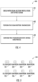
- FIG. 2 is a diagram of an example PBCH beam hopping transmission based on beam hopping patterns 200. While each step of the method 200 in FIG. 2 is shown and described separately, multiple steps may be executed in a different order than what is shown, in parallel with each other, or concurrently with each other.
- the method of FIG. 2 may be performed by a TRP for exemplary purposes, but it may also be performed by any node operating in a wireless communications system such as base stations 114a or 114b as defined above.
- Beam hopping transmissions for PBCH may be performed based on predefined beam hopping patterns. Several hopping patterns for beams may be used. For example, even and odd beams may be used as the beam hopping pattern.
- a TRP or base station may perform beam sweeping on the even beams or odd beams.
- the even and odd beams may be swept alternately in time or frequency during different beam sweeping cycles.
- Beams may also be partitioned into multiple subsets of beams. Each subset of beams may be swept in different time or different beam sweeping bursts.
- beams may be swept more frequently than the beam subset ⁇ j with lower frequency, f j , for f i > f j .
- a TRP may obtain a beam hopping pattern 201.
- a PBCH beam hopping transmission may then be performed 202 based on the determined beam hopping pattern.
- PBCH beam hopping transmission may continue with the same beam hopping pattern 203.
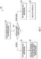
- FIG. 3 is a diagram of an example PBCH beam hopping transmission with a distribution based beam hopping pattern 300. While each step of the method 300 in FIG. 3 is shown and described separately, multiple steps may be executed in a different order than what is shown, in parallel with each other, or concurrently with each other.
- the method of FIG. 3 may be performed by a TRP for exemplary purposes, but it may also be performed by any node operating in a wireless communications system such as base stations 114a or 114b as defined above.
- the beam hopping pattern may be obtained 301, and the PBCH beam hopping transmission may then be performed 302 based on the determined beam hopping pattern.
- the PBCH beam hopping transmission may continue with the selected beam hopping pattern 303.
- the WTRU direction distribution may be obtained 304.
- the beam hopping pattern may be changed as a function of the WTRU direction distribution 305.
- the PBCH beam hopping transmission may continue with different beam hopping pattern and/or different beam sweep frequencies as a function of the WTRU direction distribution 306.
- the beam hopping transmission used in the examples described herein may be performed based on a WTRU beam-location profile that may be acquired by a TRP or base station.
- a WTRU beam-location profile may be acquired by a TRP or base station.
- an ACK-to-PBCH scheme may be used to acquire the WTRU beam-location profile.
- a WTRU may detect a PBCH signal for a particular beam, and it may send back an ACK to respond to that beam.
- the TRP or base station may obtain the beam-location profile of the WTRU according to the reported ACKs for PBCH beams.
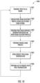
- FIG. 4 is a diagram of an example PBCH beam hopping transmission based on a beam-location profile 400. While each step of the method 400 in FIG. 4 is shown and described separately, multiple steps may be executed in a different order than what is shown, in parallel with each other, or concurrently with each other.
- the method of FIG. 4 may be performed by a TRP for exemplary purposes, but it may also be performed by any node operating in a wireless communications system such as base stations 114a or 114b as defined above.
- the TRP may first obtain the beam-location profile of WTRUs for the TRP or cell by using the ACK-to-PBCH scheme 401.
- the TRP may perform a PBCH beam hopping transmission 403 based on the obtained beam-location profile of the WTRUs.
- the TRP may continue PBCH transmission using beam hopping scheme with inverse-HARQ processes to achieve efficiency.
- the TRP or base station may transmit a PBCH signal in different directions using beam sweeping.
- the WTRU may send back an ACK to respond to that beam.
- the TRP or base station may receive the ACK of the beam and may learn the beam-location profile of the WTRU.
- Each WTRU may send an ACK as long as it detects a PBCH signal in that beam.
- a cyclic redundancy check (CRC) - based ACK scheme may be used. For example, when the WTRU detects a PBCH signal and decodes it successfully (i.e., it passes the CRC test for a particular beam), a beam-specific ACK may be generated and reported by the WTRU with respect to that beam.
- the base station may mark the beam that has been ACK-ed when the base station receives the ACK.
- the base station may maintain a list of beams that have been ACK-ed. The next time the base station transmits PBCH, it may perform beam sweep on those beams which have been ACK-ed.
- the ACK-to-PBCH scheme may provide the beam-location profile of WTRUs.
- the ACK-to-PBCH scheme may be used to implement PBCH beam hopping for PBCH transmissions.
- the PBCH beam hopping transmission may be energy efficient due to fewer beams participating in the beam sweep. It may also reduce the interference in a cell or to other cells due to the reduced broadcasting signal.
- the PBCH beam hopping transmission may also reduce latency due to potential shorter beam sweep. A short beam sweeping burst may be used to enable beam hopping to achieve low latency.
- a beam-location profile may not change.
- WTRU mobility increases, the beam-location profile may change with time. Therefore, a continuing update of beam-location profile may be beneficial.
- Inverse HARQ processes may be used to update and refine the beam-location profile of WTRUs. However, over time the beam-location profile may be updated. This may be done by a full beam sweep.
- a TRP or base station may perform a full beam sweep after N TTIs. The variable N may be configurable by the TRP or base station. In between two cycles of a full beam sweep, beam hopping may be used.
- a full beam sweep may be used to reset and update the beam-location profile of WTRUs and ensure the WTRUs receive the PBCH signal in beams of one or more of the directions.
- a hybrid PBCH transmission method using full beam sweeping and beam hopping sweeping may be used.
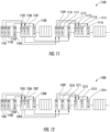
- FIG. 5 is a diagram of an example hybrid PBCH transmission burst using a both full beam sweep to reset and a beam hopping sweep 500.
- Full beam sweep 501 for PBCH transmission may be first performed, followed by one or multiple beam hopping sweeping 502, 503, 504.
- Full beam sweeping 505 may be performed after N full TTIs while beam hopping sweep 506, 507, 508 may be performed after N hop TTIs and N hop ⁇ N full .
- the WTRU may perform the following actions. First, the WTRU may wait until next full beam sweeping to receive the PBCH signal again. Alternatively, for a preset timer, if the WTRU still does not receive PBCH signal, the WTRU may initiate an UL SYNC signal to request a PBCH signal.
- the base station may switch between energy saving mode and regular mode for PBCH transmission.
- the TRP or base station may switch to regular mode for PBCH transmission.
- the TRP or base station may switch to power saving mode for PBCH transmission. That is, the TRP or base station may not transmit PBCH in one or more directions or in one or more beams. Instead the TRP or base station may transmit PBCH in certain directions or beams based on the obtained beam-location profile.
- the TRP or base station may also switch to power saving mode for PBCH transmission.
- the system information may contain a small portion of the total amount of system information that the WTRU may need.
- the remaining system information may be provided to the WTRU once it has accessed the network or system by other ways.
- the remaining system information may be provided to the WTRU by dedicated signaling or WTRU-specific signaling. It may be beneficial to deploy multi-beam based operation for standalone NR carriers to enhance the performance. On the other hand, efficient multi-beam based operation may reduce the overhead due to MIB and/or SIB transmission that employs beam sweeping.
- the contents of at least part of the SFN and CRC bits may be encoded together with other configuration information for the NR PBCH.
- These messages may be encoded by a polar code with a very low code rate. Instead of using repetition on top of a mother code rate of 1/3 TBCC code as in LTE, a mother code rate of, for example, a 1/12 polar code may be applied. This direct design of a low code rate polar code may achieve better performance as the codeword length is larger.
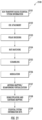
- FIG. 22 is a diagram of an example method of incorporating system information into the PBCH using joint polar transformation encoding and rate matching 2200 in accordance with one example, which may be used in combination with any of the examples described herein. While each step of the method 2200 in FIG. 22 is shown and described separately, multiple steps may be executed in a different order than what is shown, in parallel with each other, or concurrently with each other.
- the method of FIG. 22 may be performed by a TRP for exemplary purposes, but it may also be performed by any node operating in a wireless communications system such as base stations 114a or 114b as defined above.
- a PBCH transport block with essential system information 2201 may be attached with CRC bits 2202.
- an additional one or two bits may be included to make the payload 31 or 32 bits, which may include some additional reserved bits.
- the information bit size may be 15 or 16 bits.
- a 16-bit CRC may also still be used. Since the code rate may be increased, 15 or 16 bits, plus some reserved bits, may still be accommodated by the same resources of the PBCH without sacrificing performance due to extra gain achieved by using polar encoding.
- the additional 1 or 2 bits in this example may be used to indicate the beam sweeping configurations.
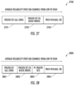
- the TRP may then prioritize the concatenated MIB 2410 and the at least 16 CRC bits 2411 based on their content 2412 such that bits associated with more important information are placed at the beginning of the concatenated MIB 2410 and CRC bits 2411 and bits associated with less important information are placed at the end of MIB 2410 and CRC bits 2411. This process is aimed to make use of the polarization feature of polar codes so that the more important bits are sent through more reliable bit channels.
- the TRP may then perform channel coding of the prioritized concatenated MIB and the at least 16 CRC bits using a polar encoder with a very low coding rate 2413, such as for example a rate less than 1/3. Since polar codes are flexible on their information input bits, the coding rate of polar code may not be restricted to certain values. Unlike a TBCC code, which may have a fixed rate of 1/3, a lower coding rate may be used when performing channel coding of the prioritized bits. Furthermore, this may be done at no additional cost. In LTE, rate 1/3 TBCC code may be used followed by repetition to achieve an effectively low coding rate. However, in NR a polar code may be directly used with a much lower coding rate while avoiding the repetition operations. The direct usage of a low coding rate polar code may provide an improved coding gain.
- the codeword length of the polar code may be a power of 2.
- the order of input may be changed when it is compared with the inclusion of the bit reversing matrix.
- the TRP may then perform rate matching on the polar coded bits 2414 such as for example via repetition.
- the output bits of the rate matching block may then be assigned to the PBCH of a radio frame for transmission, and the same PBCH data may also be transmitted in the PBCHs of consecutively transmitted radio frames 2415.
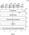
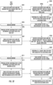
- FIG. 25 is a diagram of an NR PBCH coding method 2500 in accordance with another example, which may be used in combination with any of the examples described herein. As in the above example, polar codes are also used to encode the MIB message in the example of FIG. 25 . While each step of the method 2500 in FIG. 25 is shown and described separately, multiple steps may be executed in a different order than what is shown, in parallel with each other, or concurrently with each other.
- the method of FIG. 25 is performed by a TRP for exemplary purposes, but it may also be performed by any node operating in a wireless communications system such as base stations 114a or 114b as defined above. In the example of FIG.
- a TRP may generate a concatenated MIB transport block that includes information bits associated with extended content such as system bandwidth information 2501, PHICH configuration information 2502, SFN 2503, beam sweeping configuration 2504, and RACH configuration and other system information 2505. There may be reserved bits 2506 in the MIB as well.
- the TRP may then attach at least 16 CRC bits 2511 to concatenated MIB 2510.
- the CRC bits 2511 may be generated by cyclic generator polynomials using, for example, Equation (1) above. Other cyclic generator polynomials may also be used.
- the CRC bits 2511 may be appended to the information bits (system bandwidth information 2501, PHICH configuration information 2502, SFN 2503, beam sweeping configuration 2504, and RACH configuration and other system information 2505), or they may be put in different relative locations to the information bits.
- the number of CRC bits 2511 may be more than 16 bits. Furthermore, if a PC polar code is used to encode the NR-PBCH payload, the number of CRC bits 2511 may be equal to 16 bits.
- the TRP may then prioritize 2512 the concatenated MIB 2510 and the at least 16 CRC bits 2511 based on various criteria such as content as described above, which results in the bits associated with more important information are placed at the beginning of the concatenated MIB 2510 and CRC bits 2511 and bits associated with less important information are placed at the end of MIB 2510 and CRC bits 2511.
- This process is aimed to make use of the polarization feature of polar codes so that the more important bits are sent through more reliable bit channels.
- the TRP may then perform channel coding of the prioritized concatenated MIB and the at least 16 CRC bits using a polar encoder with a very low coding rate 2513.
- polar codes are flexible on their information input bits, the coding rate of polar code may not be restricted to certain values and a much lower coding rate may be used for polar codes.
- the codeword length of the polar code may be a power of 2.
- the generator matrix of the polar code may be expressed by Equation (2) above.
- Polar encoding may be expressed by Equation (3) above.
- the polar code may also be configured without the bit reversing at the encoder as expressed by Equation (4) above. In this configuration, the order of input may be changed when it is compared with the inclusion of the bit reversing matrix.
- the TRP may then perform a puncturing 2514 operation on the coded bits to fit the given resource blocks for the PBCH.
- the output of the puncturing block may be a bit sequence of arbitrary length.
- the TRP may then fit the output of the puncturing block in the PBCH of a radio frame for transmission, and same PBCH data may also be transmitted in the PBCHs of consecutively transmitted radio frames 2515.
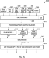
- FIG. 26 is a diagram an example NR PBCH coding procedure 2600 in accordance with yet another example, which may be used in combination with any of the examples described herein.
- polar codes are also used to encode the MIB message in the example of FIG. 26 . While each step of the method 2600 in FIG. 26 is shown and described separately, multiple steps may be executed in a different order than what is shown, in parallel with each other, or concurrently with each other.
- the method of FIG. 26 is performed by a TRP for exemplary purposes, but it may also be performed by any node operating in a wireless communications system such as base stations 114a or 114b as defined above. It should be noted that deep puncturing may severely degrade the performance of polar codes. To improve the coding performance, the example of FIG. 26 uses an alternative rate matching scheme.
- a TRP may generate a concatenated MIB transport block that includes information bits associated with extended content such as system bandwidth information 2601, PHICH configuration information 2602, SFN 2603, beam sweeping configuration 2604, and RACH configuration and other system information 2605. There may be reserved bits 2606 in the MIB as well.
- the TRP may then attach at least CRC bits 2611 to concatenated MIB 2610.
- the CRC bits 2611 may be generated by cyclic generator polynomials using, for example, Equation (1) above. Other cyclic generator polynomials may also be used.
- the CRC bits 2611 may be appended to the information bits (system bandwidth information 2601, PHICH configuration information 2602, SFN 2603, beam sweeping configuration 2604, and RACH configuration and other system information 2605), or they may be put in different relative locations to the information bits.
- the TRP may use multiple polar codes with different lengths.
- the TRP may prioritize the concatenated MIB 2610 and CRC bits 2611 to the multiple polar code blocks 2612 based on various criteria such as content as described in the previous examples above.
- L polar codes by polar encoders 2613, 2614, and 2615 may be used, and the i -th polar code may have a codeword length 2 n i ,1 ⁇ i ⁇ L .
- the selection of L and n 1 , ..., n L may depend on the coded block length of the PBCH in each radio frame.
- X resource elements may be allocated for the PBCH in each radio frame and QPSK modulation may be used.
- the coded block length of the PBCH may be 2X bits.
- the coded block length of PBCH may be 480 bits.
- 4 polar codes may be selected with respective codeword lengths of 256 bits, 128 bits, 64 bits and 32 bits.
- the prioritized mapping to multiple polar code blocks 2612 may be considered as a matrix production operation.
- the input to this block may be a vector A of t bits.
- the output may be calculated as A ⁇ W in a GF(2) field.
- the design of the matrix W may also consider the importance of the input bits.
- the first n 1 bits of the outputs may be encoded by polar code 1 with length n 1
- the next n 2 bits of the outputs may be encoded by polar code 2 with length n 2 , etc.
- the outputs of these L polar codes may be concatenated 2617. These concatenated bits may be further scrambled and modulated to fit in a PBCH of a radio frame for transmission, and the same PBCH data may also be transmitted in the PBCHs of consecutively transmitted radio frames 2618.
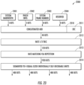
- FIG. 27 is a diagram of an example of PBCH polar encoding with an implicit synchronization signal (SS) block index 2700 in accordance with an example, which may be used in combination with any of the examples described herein.
- the NR-PBCH may be transmitted and multiplexed together with PSS and SSS signals within a SS block.
- the SS block index may be contained in NR-PBCH.
- the SS block index may be implicitly indicated by NR-PBCH, via operations on the polar codes.
- the SS block index may be implicitly encoded via polar codes by putting the SS block index 2702 as frozen bits in polar codes.
- a TRP may encode the NR PBCH payload together with the SS block index bits and CRC bits as information bits. This may imply that the SS block index is explicitly contained in NR-PBCH.
- the SS block index may be placed in the locations of frozen bits which may not be encoded as information bits.
- the WTRU may perform the blind detection using the four possible values of 00, 01, 10, or 11 for frozen bits.
- the WTRU may perform the polar decoding using four possible fixed frozen bit values of 00, 01, 10, or 11. Only the proper values on the frozen bits may result in the correct decoding at the WTRU side.
- the SS block index may be implicitly detected together with the NR PBCH message.
- the SS block index may also be XOR-ed or scrambled by a cell ID, or part of a cell ID, to reduce the false alarm rate.
- the NR-PBCH may also include another frozen set of all zero 2701 before the SS block index 2702 frozen set and PBCH payload and CRC 2702.
- FIG. 28 is a diagram of PBCH PC polar encoding with an implicit SS block index in frozen bits 2800 in accordance with an example, which may be used in combination with any of the examples described herein.
- the example of FIG. 28 shows that the NR-PBCH may also include another frozen set of all zero 2801 before the SS block index 2802 frozen set, PC frozen sets 2803, and PBCH payload and CRC 2804.
- FIG. 29 is a diagram of an example of PBCH PC polar encoding with a SS block index in PC frozen bits 2900 in accordance with an example, which may be used in combination with any of the examples described herein.
- the example of FIG. 29 shows that the NR-PBCH may also include another frozen set of all zero 2901 before the PC frozen set XOR-ed with the SS Block index 2902 and PBCH payload and CRC 2903.
- FIG. 30 is an example of WTRU communication with two TRPs 3000 in accordance with an example, which may be used in combination with any of the examples described herein.
- TRP1 3001 may be, for example, a macro cell or gNB.
- TRP2 3002 may be, for example, a small cell that may be within the coverage area of TRP1 3001.
- TRP1 3001 may be used to assist WTRU 3003 with one or more procedures, such as cell search, TRP selection, and/or beam selection, with or for a TRP2 3002.
- Assistance information, data, and/or parameters that a TRP may provide to a WTRU and/or that may be used by a WTRU may be referred to as WTRU-assistance data.
- Assistance information, data and/or parameters that a TRP may provide to another TRP and/or that may be used by another TRP may be referred to as TRP-assistance data.
- TRP1 3001 may be considered a primary TRP, or an anchor TRP.
- TRP2 3002 may be considered a secondary TRP, or a non-anchor TRP.
- Communication with the TRP1 3001 and TRP2 3002 may be with the same or different radio access technology (RAT).
- RAT radio access technology
- TRP1 3001 and TRP2 3002 may also be co-located, or a gNB and TRP2 may be co-located and the gNB may be an anchor cell.
- TRP1 3001 may or may also provide assistance to TRP2 3002, for example, to enable TRP2 3002 to transmit at least some of its signals (e.g., sync, reference, etc.) more efficiently.
- WTRU 3003 may be in communication with the TRP1 3001, which may transmit assistance data to WTRU 3003 for one or more other TRPs.
- WTRU 3003 may receive assistance information from TRP1 3001.
- the assistance data may enable WTRU 3003 to synchronize with and/or receive one or more signals, channels, and/or data from TRP2 3002.
- the one or more signals may include a synchronization signal, broadcast signal, reference signal, or the like.
- the one or more channels may include a control channel, a data channel, and/or a broadcast channel.
- Data may be user data or system information. It should be noted that the terms information and data may be used interchangeably herein.
- a first synchronization step may comprise at least synchronization with NR-PSS.
- a second synchronization step may comprise at least synchronization with NR-SSS.
- Assistance data may refer to WTRU-assistance data and/or TRP-assistance data.
- the assistance data for example from a first TRP, may include at least one of the following parameters for a second TRP:
- Timing and/or transmission parameters related to reference signals e.g., beam reference signals
- Aa beam sweeping procedure or method such, as forward hierarchical beam sweep using successively narrower beams or backward hierarchical beam sweep using successively wider beams;
Landscapes
- Engineering & Computer Science (AREA)
- Signal Processing (AREA)
- Computer Networks & Wireless Communication (AREA)
- Physics & Mathematics (AREA)
- Probability & Statistics with Applications (AREA)
- Theoretical Computer Science (AREA)
- Computer Security & Cryptography (AREA)
- Mobile Radio Communication Systems (AREA)
Applications Claiming Priority (5)
| Application Number | Priority Date | Filing Date | Title |
|---|---|---|---|
| US201662401024P | 2016-09-28 | 2016-09-28 | |
| US201662416615P | 2016-11-02 | 2016-11-02 | |
| US201762454491P | 2017-02-03 | 2017-02-03 | |
| EP17784749.8A EP3520260B1 (de) | 2016-09-28 | 2017-09-28 | Effizienter rundfunkkanal in strahlgeformten systemen für new radio |
| PCT/US2017/054160 WO2018064407A1 (en) | 2016-09-28 | 2017-09-28 | Efficient broadcast channel in beamformed systems for nr |
Related Parent Applications (2)
| Application Number | Title | Priority Date | Filing Date |
|---|---|---|---|
| EP17784749.8A Division-Into EP3520260B1 (de) | 2016-09-28 | 2017-09-28 | Effizienter rundfunkkanal in strahlgeformten systemen für new radio |
| EP17784749.8A Division EP3520260B1 (de) | 2016-09-28 | 2017-09-28 | Effizienter rundfunkkanal in strahlgeformten systemen für new radio |
Publications (2)
| Publication Number | Publication Date |
|---|---|
| EP4472294A2 true EP4472294A2 (de) | 2024-12-04 |
| EP4472294A3 EP4472294A3 (de) | 2025-01-22 |
Family
ID=60117769
Family Applications (2)
| Application Number | Title | Priority Date | Filing Date |
|---|---|---|---|
| EP24207029.0A Pending EP4472294A3 (de) | 2016-09-28 | 2017-09-28 | Effizienter rundfunkkanal in strahlgeformten systemen für new radio |
| EP17784749.8A Active EP3520260B1 (de) | 2016-09-28 | 2017-09-28 | Effizienter rundfunkkanal in strahlgeformten systemen für new radio |
Family Applications After (1)
| Application Number | Title | Priority Date | Filing Date |
|---|---|---|---|
| EP17784749.8A Active EP3520260B1 (de) | 2016-09-28 | 2017-09-28 | Effizienter rundfunkkanal in strahlgeformten systemen für new radio |
Country Status (4)
| Country | Link |
|---|---|
| US (3) | US11356202B2 (de) |
| EP (2) | EP4472294A3 (de) |
| CN (3) | CN118054824A (de) |
| WO (1) | WO2018064407A1 (de) |
Families Citing this family (42)
| Publication number | Priority date | Publication date | Assignee | Title |
|---|---|---|---|---|
| WO2015142664A1 (en) | 2014-03-20 | 2015-09-24 | Interdigital Patent Holdings, Inc. | Method and apparatus for non-orthogonal access in lte systems |
| CN107409370B (zh) | 2014-12-23 | 2020-08-21 | Idac控股公司 | 通过wtru执行的用于传达数据的方法及wtru |
| US10727926B2 (en) * | 2016-08-09 | 2020-07-28 | Telefonaktiebolaget Lm Ericsson (Publ) | Systems and methods for adaptive initial synchronization beam sweep |
| JP2019534615A (ja) | 2016-09-28 | 2019-11-28 | アイディーエーシー ホールディングス インコーポレイテッド | ビームフォーミングシステムにおけるNew Radioランダムアクセス |
| CN118054824A (zh) * | 2016-09-28 | 2024-05-17 | 交互数字专利控股公司 | 用于nr的波束形成系统中的有效广播信道 |
| US10470191B2 (en) * | 2016-12-09 | 2019-11-05 | Samsung Electronics Co., Ltd. | Method and apparatus of broadcast signals and channels for system information transmission |
| DK3579636T3 (da) | 2017-02-03 | 2025-08-18 | Ntt Docomo Inc | Brugerterminal og trådløs kommunikationsfremgangsmåde |
| WO2018145107A1 (en) * | 2017-02-06 | 2018-08-09 | Motorola Mobility Llc | Transmitting and receiving a synchronization signal block |
| PL4152675T3 (pl) * | 2017-02-07 | 2025-05-26 | Innovative Technology Lab Co., Ltd. | Sposób i aparatura do konfiguracji kanału rozgłaszania oraz nadawania i odbioru kanału rozgłaszania dla systemu komunikacyjnego |
| CN110291751B (zh) * | 2017-02-14 | 2022-02-01 | 瑞典爱立信有限公司 | 用于在无线通信网络中关联载波的方法和装置 |
| US10568102B2 (en) | 2017-02-23 | 2020-02-18 | Qualcomm Incorporated | Usage of synchronization signal block index in new radio |
| WO2018165894A1 (en) * | 2017-03-15 | 2018-09-20 | Nokia Technologies Oy | Early termination with distributed crc polar codes |
| KR102489996B1 (ko) * | 2017-03-22 | 2023-01-18 | 삼성전자 주식회사 | 랜덤 액세스(rach) 절차 동안 초기 빔 정렬을 수행하는 방법 및 사용자 장치 |
| WO2018201404A1 (en) * | 2017-05-04 | 2018-11-08 | Qualcomm Incorporated | Polar codes for uplink control information |
| EP4089941A1 (de) * | 2017-05-05 | 2022-11-16 | Telefonaktiebolaget LM Ericsson (publ) | Polarcodierung für strahlabtastenden rundfunkkanal |
| US11146356B2 (en) * | 2017-05-12 | 2021-10-12 | Telefonaktiebolaget Lm Ericsson (Publ) | Adaptive CRC length for beam sweeping |
| US10601447B2 (en) * | 2017-05-15 | 2020-03-24 | Qualcomm Incorporated | Field prioritization for polar codes |
| US11240720B2 (en) * | 2017-06-02 | 2022-02-01 | FG Innovation Company Limited | Methods, devices, and systems for service-driven mobility management |
| CN109150376B (zh) * | 2017-06-16 | 2022-02-15 | 大唐移动通信设备有限公司 | 一种信道编码方法及设备 |
| EP3635890B1 (de) * | 2017-09-11 | 2023-08-09 | Huawei Technologies Co., Ltd. | Verfahren und vorrichtung zur polaren kodierung von informationen mit bits zur angabe einer version eines kodierten codewortes |
| EP3692760B1 (de) * | 2017-10-05 | 2026-04-15 | Sony Group Corporation | Basisstationen und benutzergeräte mit konfiguration zur handhabung von systeminformation auf anfrage in 5g nr |
| US10715371B2 (en) | 2017-11-01 | 2020-07-14 | Samsung Electronics Co., Ltd. | Method and apparatus of NR RMSI coreset configuration in MIB |
| EP3568936B1 (de) | 2018-04-06 | 2023-10-11 | Telefonaktiebolaget LM Ericsson (publ) | Verfahren und systeme zur bestimmung einer art von systeminformationen |
| US10841149B2 (en) * | 2018-04-14 | 2020-11-17 | Qualcomm Incorporated | Beam failure recovery in connection with switching BWP |
| US11050546B2 (en) | 2018-04-30 | 2021-06-29 | At&T Intellectual Property I, L.P. | Physical downlink shared channel time domain resource allocation for 5G or other next generation network |
| US10917195B2 (en) * | 2018-05-21 | 2021-02-09 | Qualcomm Incorporated | Control channel mother code determination for multi-transmission configuration indication communication |
| US10986694B2 (en) * | 2018-07-02 | 2021-04-20 | Qualcomm Incorporated | Techniques to order direction signals during discontinuous reception |
| US11903032B2 (en) | 2018-08-13 | 2024-02-13 | Qualcomm Incorporated | Downlink data transmission in RRC inactive mode |
| US11616595B2 (en) * | 2018-10-09 | 2023-03-28 | Qualcomm Incorporated | Multi-channel listen before talk with wideband transmission in new radio in unlicensed spectrum |
| US10834604B1 (en) * | 2019-01-07 | 2020-11-10 | Sprint Communications Company L.P. | Wireless beamforming to facilitate ultra reliable low latency communication (URLLC) service |
| CN111510873B (zh) * | 2019-01-11 | 2022-02-25 | 中国信息通信研究院 | 一种用于多点发送的下行控制方法和信令 |
| US11909526B2 (en) * | 2019-06-17 | 2024-02-20 | Nec Corporation | Methods for communication, terminal device, network device, and computer readable medium |
| CN112671439A (zh) * | 2019-10-16 | 2021-04-16 | 上海华为技术有限公司 | 一种基于波束成形的通信方法和网络设备 |
| CN115004794B (zh) | 2020-08-07 | 2025-06-17 | 中兴通讯股份有限公司 | 一种用于参考信号时间同步与校准的方法 |
| KR102866455B1 (ko) | 2020-10-06 | 2025-09-29 | 오피노 엘엘씨 | 제어 채널 반복에서의 리소스 결정 |
| US20220124702A1 (en) * | 2020-10-16 | 2022-04-21 | Qualcomm Incorporated | Dynamic repetition for a control channel |
| CN113507719B (zh) * | 2021-06-29 | 2023-05-26 | 紫光展锐(重庆)科技有限公司 | 信号传输方法及相关装置 |
| US12256235B2 (en) * | 2021-08-05 | 2025-03-18 | Qualcomm Incorporated | Frequency domain beam sweep by assisting nodes |
| WO2023063858A1 (en) * | 2021-10-14 | 2023-04-20 | Telefonaktiebolaget Lm Ericsson (Publ) | A node and method therein for enabling communication link establishment towards wireless devices of a wireless communications network |
| CN115001550B (zh) * | 2022-05-26 | 2023-11-14 | 西安电子科技大学 | 毫米波系统的多用户波束快速对准方法 |
| US20240205912A1 (en) * | 2022-12-20 | 2024-06-20 | Qualcomm Incorporated | Sidelink feedback for network energy savings |
| US12418359B2 (en) | 2023-12-28 | 2025-09-16 | Ati Technologies Ulc | Devices, systems, and methods for performing lane-specific error detection in high-speed data links |
Family Cites Families (48)
| Publication number | Priority date | Publication date | Assignee | Title |
|---|---|---|---|---|
| US6324395B1 (en) * | 1998-11-18 | 2001-11-27 | Ericsson Inc. | Apparatus and methods for assigning spectral and non-spectral resource charges in wireless communications systems |
| US8135359B2 (en) * | 2008-01-04 | 2012-03-13 | Nokia Corporation | Method and apparatus for conveying antenna configuration information |
| US9042240B2 (en) * | 2009-07-31 | 2015-05-26 | Qualcomm Incorporated | Systems, apparatus and methods for broadcast channel decoding |
| WO2014065600A1 (en) * | 2012-10-24 | 2014-05-01 | Samsung Electronics Co., Ltd. | Method and apparatus for transmitting and receiving common channel information in wireless communication system |
| US9729264B2 (en) * | 2013-01-18 | 2017-08-08 | Lg Electronics Inc. | Interference-removed reception method and terminal |
| KR20150020296A (ko) * | 2013-08-13 | 2015-02-25 | 주식회사 케이티 | 시스템 정보 송수신 방법 및 그 장치 |
| CN103414540A (zh) | 2013-08-14 | 2013-11-27 | 南京邮电大学 | 一种基于Polar码的退化窃听信道速率兼容方法 |
| US9467164B2 (en) * | 2013-10-01 | 2016-10-11 | Texas Instruments Incorporated | Apparatus and method for supporting polar code designs |
| CN105493424B (zh) * | 2013-12-31 | 2019-02-01 | 华为技术有限公司 | 一种Polar码的处理方法、系统及无线通信装置 |
| KR102235637B1 (ko) * | 2014-01-29 | 2021-04-05 | 삼성전자주식회사 | 무선 통신 시스템에서 D2D(Device to Device) 통신의 자원 할당을 통한 송신/수신 단말의 동작 방법 및 장치 |
| BR112016021434A2 (pt) * | 2014-03-19 | 2017-08-15 | Huawei Tech Co Ltd | Método de equiparação de taxa de código polar e aparelho de equiparação de taxa |
| US9419656B2 (en) * | 2014-07-29 | 2016-08-16 | Intel IP Corporation | Decoder and method for decoding an encoded sequence of bits |
| US9954645B2 (en) | 2014-12-05 | 2018-04-24 | Lg Electronics Inc. | Method and device for providing secure transmission based on polar code |
| RU2685034C2 (ru) * | 2014-12-22 | 2019-04-16 | Хуавэй Текнолоджиз Ко., Лтд. | Устройство кодирования и способ кодирования полярным кодом |
| EP3758420B1 (de) * | 2015-01-30 | 2024-07-17 | Samsung Electronics Co., Ltd. | Verwaltung eines systeminformationsblocks in einem drahtloskommunikationsnetzwerk |
| RU2682017C1 (ru) * | 2015-03-10 | 2019-03-14 | Хуавэй Текнолоджиз Ко., Лтд. | Способ и устройство связи для передачи информации |
| KR20160137153A (ko) * | 2015-05-22 | 2016-11-30 | 삼성전자주식회사 | 통신 시스템에서 방송 정보 수신 방법 및 장치 |
| US10368343B2 (en) * | 2015-05-27 | 2019-07-30 | Telefonaktiebolaget L M Ericsson (Publ) | Systems and methods for downlink scheduling that mitigate PDCCH congestion |
| EP4318996A3 (de) * | 2015-07-30 | 2024-02-21 | Apple Inc. | Entwurf eines physikalischen rundfunkkanals |
| US10461779B2 (en) * | 2015-08-12 | 2019-10-29 | Telefonaktiebolaget Lm Ericsson (Publ) | Rate-compatible polar codes |
| KR102607575B1 (ko) * | 2015-11-16 | 2023-11-30 | 삼성전자주식회사 | 무선 통신 시스템에서 방송 정보 수신을 위한 방법 및 장치 |
| US11424855B2 (en) * | 2015-12-28 | 2022-08-23 | Qualcomm Incorporated | Physical broadcast channel (PBCH) and master information block (MIB) design |
| CN105811998B (zh) | 2016-03-04 | 2019-01-18 | 深圳大学 | 一种基于密度演进的极化码构造方法及极化码编译码系统 |
| WO2017193296A1 (en) * | 2016-05-11 | 2017-11-16 | Qualcomm Incorporated | Techniques for a hybrid automatic repeat request (harq) mechanism with polar codes |
| US10630410B2 (en) * | 2016-05-13 | 2020-04-21 | Telefonaktiebolaget Lm Ericsson (Publ) | Network architecture, methods, and devices for a wireless communications network |
| US10291264B2 (en) * | 2016-06-17 | 2019-05-14 | Huawei Technologies Co., Ltd. | Systems and methods for rate matching when using general polar codes |
| CN114915374B (zh) * | 2016-08-10 | 2024-12-27 | 交互数字专利控股公司 | 用于控制信息的基于优先级的信道编码 |
| KR102683634B1 (ko) * | 2016-08-22 | 2024-07-11 | 삼성전자 주식회사 | 통신 시스템에서 초기 접속을 수행하는 방법 및 장치 |
| US10405332B2 (en) * | 2016-09-06 | 2019-09-03 | Samsung Electronics Co., Ltd. | Coexistence of different radio access technologies or services on a same carrier |
| CN117375766A (zh) * | 2016-09-14 | 2024-01-09 | 华为技术有限公司 | 信息传输的方法、发送端设备和接收端设备 |
| CN118054824A (zh) * | 2016-09-28 | 2024-05-17 | 交互数字专利控股公司 | 用于nr的波束形成系统中的有效广播信道 |
| US10389567B2 (en) * | 2016-11-03 | 2019-08-20 | Samsung Electronics Co., Ltd. | Method and apparatus for synchronization signal design |
| US10470191B2 (en) * | 2016-12-09 | 2019-11-05 | Samsung Electronics Co., Ltd. | Method and apparatus of broadcast signals and channels for system information transmission |
| US10931311B2 (en) * | 2017-01-03 | 2021-02-23 | Lg Electronics Inc. | Method for encoding and transmitting PBCH and communication device therefor |
| KR102730802B1 (ko) * | 2017-01-25 | 2024-11-18 | 삼성전자주식회사 | 무선 통신 시스템에서 동기 신호를 검출하는 방법 및 장치 |
| US11223370B2 (en) * | 2017-02-17 | 2022-01-11 | Lg Electronics Inc. | Method and apparatus for transmitting information |
| CN108462554B (zh) * | 2017-02-17 | 2021-06-15 | 华为技术有限公司 | 一种极性码的传输方法和装置 |
| CN108574561B (zh) * | 2017-03-14 | 2020-11-17 | 华为技术有限公司 | 极化码编码的方法和装置 |
| CN110463046B (zh) * | 2017-03-24 | 2023-09-05 | 苹果公司 | 用于nr的码块分割和动态crc大小自适应 |
| CN110476357B (zh) * | 2017-04-01 | 2021-08-20 | 华为技术有限公司 | 极化码传输方法和装置 |
| US10660102B1 (en) * | 2017-06-27 | 2020-05-19 | Mbit Wireless, Inc. | Method and apparatus for broadcast channel decoder |
| CN117118568A (zh) * | 2017-08-10 | 2023-11-24 | 艾普拉控股有限公司 | 用于生成物理广播信道信号的方法及相关装置和存储介质 |
| CN109525362B (zh) * | 2017-09-18 | 2024-07-16 | 华为技术有限公司 | 一种极性码的编码方法和编码装置 |
| US10925032B2 (en) * | 2017-10-02 | 2021-02-16 | Mediatek Inc. | Polar bit allocation for partial content extraction |
| WO2019098677A1 (ko) * | 2017-11-16 | 2019-05-23 | 엘지전자 주식회사 | Pbch 전송 방법 및 전송 장치, 및 pbch 수신 방법 및 수신 장치 |
| WO2019095330A1 (en) * | 2017-11-17 | 2019-05-23 | Zte Corporation | Predetermined master information block coding |
| KR102541319B1 (ko) * | 2018-03-29 | 2023-06-08 | 삼성전자주식회사 | 무선 통신 시스템에서 극 부호를 이용한 부호화 및 복호화를 위한 장치 및 방법 |
| US10917195B2 (en) * | 2018-05-21 | 2021-02-09 | Qualcomm Incorporated | Control channel mother code determination for multi-transmission configuration indication communication |
-
2017
- 2017-09-28 CN CN202410181071.XA patent/CN118054824A/zh active Pending
- 2017-09-28 CN CN202410181069.2A patent/CN118054823A/zh active Pending
- 2017-09-28 WO PCT/US2017/054160 patent/WO2018064407A1/en not_active Ceased
- 2017-09-28 US US16/336,803 patent/US11356202B2/en active Active
- 2017-09-28 CN CN201780070235.XA patent/CN109964428A/zh active Pending
- 2017-09-28 EP EP24207029.0A patent/EP4472294A3/de active Pending
- 2017-09-28 EP EP17784749.8A patent/EP3520260B1/de active Active
-
2022
- 2022-05-05 US US17/737,616 patent/US11968041B2/en active Active
-
2024
- 2024-03-08 US US18/600,174 patent/US12531656B2/en active Active
Also Published As
| Publication number | Publication date |
|---|---|
| US20220271864A1 (en) | 2022-08-25 |
| US11968041B2 (en) | 2024-04-23 |
| CN118054823A (zh) | 2024-05-17 |
| EP3520260B1 (de) | 2025-05-07 |
| EP4472294A3 (de) | 2025-01-22 |
| CN118054824A (zh) | 2024-05-17 |
| EP3520260A1 (de) | 2019-08-07 |
| US12531656B2 (en) | 2026-01-20 |
| CN109964428A (zh) | 2019-07-02 |
| US11356202B2 (en) | 2022-06-07 |
| WO2018064407A1 (en) | 2018-04-05 |
| US20240214117A1 (en) | 2024-06-27 |
| US20190238270A1 (en) | 2019-08-01 |
Similar Documents
| Publication | Publication Date | Title |
|---|---|---|
| US12531656B2 (en) | Efficient broadcast channel in beamformed systems for NR | |
| US12137404B2 (en) | Methods and systems for beamformed system information transmission | |
| US12408152B2 (en) | Random access in new radio (NR) and other beamforming systems | |
| US11716704B2 (en) | Beamformed paging transmission | |
| EP4009719B1 (de) | Effiziente verwendung von ssbs in new-radio-systemen | |
| WO2025010316A1 (en) | Methods and apparatuses for multi-pusch retransmission | |
| WO2025010328A1 (en) | Methods and apparatuses for multi-pusch transmission with hybrid stxmp mappings | |
| WO2025010323A1 (en) | Methods and apparatuses for enhanced ndi for multi-pusch transmission |
Legal Events
| Date | Code | Title | Description |
|---|---|---|---|
| PUAI | Public reference made under article 153(3) epc to a published international application that has entered the european phase |
Free format text: ORIGINAL CODE: 0009012 |
|
| STAA | Information on the status of an ep patent application or granted ep patent |
Free format text: STATUS: THE APPLICATION HAS BEEN PUBLISHED |
|
| AC | Divisional application: reference to earlier application |
Ref document number: 3520260 Country of ref document: EP Kind code of ref document: P |
|
| AK | Designated contracting states |
Kind code of ref document: A2 Designated state(s): AL AT BE BG CH CY CZ DE DK EE ES FI FR GB GR HR HU IE IS IT LI LT LU LV MC MK MT NL NO PL PT RO RS SE SI SK SM TR |
|
| REG | Reference to a national code |
Ref country code: DE Ref legal event code: R079 Free format text: PREVIOUS MAIN CLASS: H04W0048100000 Ipc: H04L0001000000 |
|
| PUAL | Search report despatched |
Free format text: ORIGINAL CODE: 0009013 |
|
| AK | Designated contracting states |
Kind code of ref document: A3 Designated state(s): AL AT BE BG CH CY CZ DE DK EE ES FI FR GB GR HR HU IE IS IT LI LT LU LV MC MK MT NL NO PL PT RO RS SE SI SK SM TR |
|
| RIC1 | Information provided on ipc code assigned before grant |
Ipc: H04W 74/0833 20240101ALN20241213BHEP Ipc: H03M 13/09 20060101ALI20241213BHEP Ipc: H04W 48/10 20090101ALI20241213BHEP Ipc: H04H 20/65 20080101ALI20241213BHEP Ipc: H04B 7/06 20060101ALI20241213BHEP Ipc: H03M 13/13 20060101ALI20241213BHEP Ipc: H04L 1/00 20060101AFI20241213BHEP |
|
| STAA | Information on the status of an ep patent application or granted ep patent |
Free format text: STATUS: REQUEST FOR EXAMINATION WAS MADE |
|
| 17P | Request for examination filed |
Effective date: 20250721 |
|
| STAA | Information on the status of an ep patent application or granted ep patent |
Free format text: STATUS: EXAMINATION IS IN PROGRESS |