EP4472148A1 - Method and device for encoding battery management system - Google Patents
Method and device for encoding battery management system Download PDFInfo
- Publication number
- EP4472148A1 EP4472148A1 EP24179241.5A EP24179241A EP4472148A1 EP 4472148 A1 EP4472148 A1 EP 4472148A1 EP 24179241 A EP24179241 A EP 24179241A EP 4472148 A1 EP4472148 A1 EP 4472148A1
- Authority
- EP
- European Patent Office
- Prior art keywords
- slave control
- control board
- encoding
- bms
- message
- Prior art date
- Legal status (The legal status is an assumption and is not a legal conclusion. Google has not performed a legal analysis and makes no representation as to the accuracy of the status listed.)
- Granted
Links
Images

Classifications
-
- H—ELECTRICITY
- H04—ELECTRIC COMMUNICATION TECHNIQUE
- H04L—TRANSMISSION OF DIGITAL INFORMATION, e.g. TELEGRAPHIC COMMUNICATION
- H04L12/00—Data switching networks
- H04L12/28—Data switching networks characterised by path configuration, e.g. LAN [Local Area Networks] or WAN [Wide Area Networks]
- H04L12/40—Bus networks
- H04L12/40006—Architecture of a communication node
- H04L12/40013—Details regarding a bus controller
-
- B—PERFORMING OPERATIONS; TRANSPORTING
- B60—VEHICLES IN GENERAL
- B60L—PROPULSION OF ELECTRICALLY-PROPELLED VEHICLES; SUPPLYING ELECTRIC POWER FOR AUXILIARY EQUIPMENT OF ELECTRICALLY-PROPELLED VEHICLES; ELECTRODYNAMIC BRAKE SYSTEMS FOR VEHICLES IN GENERAL; MAGNETIC SUSPENSION OR LEVITATION FOR VEHICLES; MONITORING OPERATING VARIABLES OF ELECTRICALLY-PROPELLED VEHICLES; ELECTRIC SAFETY DEVICES FOR ELECTRICALLY-PROPELLED VEHICLES
- B60L58/00—Methods or circuit arrangements for monitoring or controlling batteries or fuel cells, specially adapted for electric vehicles
- B60L58/10—Methods or circuit arrangements for monitoring or controlling batteries or fuel cells, specially adapted for electric vehicles for monitoring or controlling batteries
-
- G—PHYSICS
- G06—COMPUTING OR CALCULATING; COUNTING
- G06F—ELECTRIC DIGITAL DATA PROCESSING
- G06F1/00—Details not covered by groups G06F3/00 - G06F13/00 and G06F21/00
- G06F1/26—Power supply means, e.g. regulation thereof
- G06F1/32—Means for saving power
- G06F1/3203—Power management, i.e. event-based initiation of a power-saving mode
-
- H—ELECTRICITY
- H04—ELECTRIC COMMUNICATION TECHNIQUE
- H04L—TRANSMISSION OF DIGITAL INFORMATION, e.g. TELEGRAPHIC COMMUNICATION
- H04L12/00—Data switching networks
- H04L12/28—Data switching networks characterised by path configuration, e.g. LAN [Local Area Networks] or WAN [Wide Area Networks]
- H04L12/42—Loop networks
- H04L12/423—Loop networks with centralised control, e.g. polling
Definitions
- the present disclosure relates to the field of battery technologies, and more particular to a method for encoding a battery management system and a device for encoding a battery management system.
- a master control board of the BMS is communicated with one or more slave control boards of the BMS via a serial bus interface such as a Controller Area Network (CAN) bus interface and a 485 bus interface, and the slave control boards of the BMS connected to the same bus is required to be distinguishable by the master control board of the BMS. Therefore, it is necessary to set different Identity Documents (IDs) for the slave control boards so as to encode the slave control boards of the BMS.
- IDs Identity Documents
- a first way is to write an ID into each of the slave control boards of the BMS by a compiler or an upper computer to complete encoding of the slave control boards
- a second way is to input an ID on each of the slave control boards of the BMS by setting a dial on the slave control board in factory or on-site assembling of the BMS to complete encoding of the slave control boards
- a third way is to count and set the number of slave control boards by the upper computer or the master control board of the BMS in on-site assembling of the BMS, so as to perform encoding of the slave control boards in a manner of the CAN communication and the hard wire digital signal transmission.
- some embodiments of the present disclosure provides a method for encoding a battery management system, where the battery management system includes a master control board and a plurality of slave control boards, the master control board is connected with each of the slave control boards by a CAN bus, the plurality of slave control boards are arranged in sequence, and the master control board is connected to a first slave control board and a last slave control board of the plurality of slave control boards via an Input Output (IO) line, a previous slave control board and a next slave control board of the slave control boards are connected via the IO line, and a plurality of pieces of pre-configured encoding information are stored in the battery management system, and the method includes:
- IO Input Output
- some embodiments of the present disclosure provides a device for encoding a battery management system, where the battery management system includes a master control board and a plurality of slave control boards, the master control board is connected with each of the slave control boards by a CAN bus, and the master control board is connected to a first slave control board and a last slave control board of the plurality of slave control boards via an Input Output (IO) line, a previous slave control board and a next slave control board of the slave control boards are connected via the IO line, and a plurality of pieces of pre-configured encoding information are stored in the battery management system, and the device includes:
- IO Input Output
- some embodiments of the present disclosure provide an electronic device, including: one or more processors; a memory; and one or more application programs, where the one or more application programs are stored in the memory and configured to be executed by the processors to implement any of the methods as described in the above first aspect.
- some embodiments of the present disclosure further provide a computer readable storage medium having stored thereon a computer program that is loaded by a processor to perform any of the methods as described in the first aspect.
- some embodiments of the present disclosure provide a battery management system, including: a BMS master control board and a plurality of BMS slave control boards, where the plurality of BMS slave control boards are arranged in sequence, the BMS master control board is connected to each of the plurality of BMS slave control boards via a CAN bus; and a hard wire encoding line connected between the BMS master control board and a first BMS slave control board of the plurality of BMS slave control boards, between the BMS master control board and a last BMS slave control board of the plurality of BMS slave control boards, and between any two adjacent ones of the plurality of BMS slave control boards; where the BMS master control board is configured to transmit an encoding message to corresponding one of the BMS slave control boards at a rear end of the hard wire encoding line via the CAN bus when a digital signal of the hard wire encoding line received by the BMS master control board is at a high level, and the BMS slave control board is configured to receive the encoding message transmitted
- some embodiments of the present disclosure provide a vehicle, including the battery management system of the fifth aspect.
- the battery management system includes a master control board and a plurality of slave control boards, the master control board is connected with each of the slave control boards by a CAN bus, the plurality of slave control boards are arranged in sequence, and the master control board is connected to a first slave control board and a last slave control board of the plurality of slave control boards via an Input Output (IO) line, and a previous slave control board and a next slave control board of the slave control boards are connected via the IO line, so as to realize a closed-loop connection between the master control board and the slave control boards without counting the number of slave control boards in advance.
- IO Input Output
- the battery management system may include a master control board and a plurality of slave control boards, where the master control board is connected with each of the slave control boards by a CAN bus, the plurality of slave control boards are arranged in sequence, and the master control board is connected to a first slave control board and a last slave control board of the plurality of slave control boards via an Input Output (IO) line, a previous slave control board and a next slave control board of the slave control boards are connected via the IO line, and a plurality of pieces of pre-configured encoding information are stored in the battery management system.
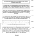
- the method for encoding the battery management system may include following steps S101-S106.
- addressing detection may be performed for each of the slave control boards to determine a detection result.
- the battery management system in the present embodiments includes a master control board 101 and a plurality of slave control boards 102, where the master control board is connected with each of the slave control boards through the CAN bus 103 to realize communication connection between the master control board 101 and each of the slave control boards 102, such as transmission and reception of a message.
- the master control board 101 is connected with the first slave control board 102 and the last slave control board 102 via an IO line 104 for transmission of a digital signal between the master control board 101 and the first slave control board 102 and between the last slave control board 102 and the master control board 101.
- the previous slave control board 102 and the next slave control board 102 of the plurality of slave control boards 102 are connected by the IO line 104 for transmission of a digital signal between two adjacent slave control boards 102.
- FIG. 2 which is architectural diagram of a battery management system.
- a communication connection between the master control board 101 and each of the slave control boards 102 is realized, and a closed-loop connection between the master control board 101 and each of the slave control boards 102 is realized, so that the efficiency of encoding the slave control boards is improved without counting the number of slave control boards 102 in advance.
- a plurality of pieces of pre-configured encoding information may be stored in the battery management system, where the encoding information is pre-configured information for encoding the slave control boards.
- the encoding information may be an identification, such as, a character, a number, or a combination of the character and the number.
- the pre-configured encoding information may be a board number, such as 1, 2, 3, ... 1000, or the like, and may be pre-configured and stored in a storage module of the battery management system.
- the addressing detection is a processing method for determining whether a current slave control board has been encoded, so as to avoid reducing of encoding efficiency by repetition encoding of the slave control boards.
- efficient addressing detection of the slave control board can be realized by comparing a message transmitted or received by the battery management system with parameter information in an Electrically Erasable Programmable Read-Only Memory (EEPROM) of the slave control board and determining a detection result according to the comparison result.
- EEPROM Electrically Erasable Programmable Read-Only Memory
- the performing of addressing detection for each of the slave control boards to obtain the detection result may include: configuring a slave control message corresponding to each of the slave control boards according to an internal parameter of the slave control board; obtaining a first check value by performing Cyclic Redundancy Check (CRC) check for the slave control message; obtaining a second check value by obtaining a master control message received by the master control board to perform CRC check for the master control message; and comparing the first check value with the second check value to determine a detection result.
- CRC Cyclic Redundancy Check
- the CRC check refers to an algorithm for performing calculation of checksum on a frame of message.
- a CRC8 check algorithm is selected.
- the first check value refers to a check value for the slave control board performing cyclic redundancy check for the slave control message configured according to the internal parameter of the slave control board.
- the second check value refers to a check value for the master control board performing cyclic redundancy check for the master control message received by the master control board. It should be noted that the first check value and the second check value use the same cyclic redundancy check algorithm, for example, the CRC8 check algorithm.
- the slave control board reads the internal parameter of the slave control board after receiving a message for the addressing detection, and configures a slave control message according to the internal parameter.
- the slave control board may use the internal parameter as the slave control message, and performs CRC check for the slave control message to obtain a first check value.
- the master control board performs CRC check for a master control message received by the mater control board to obtain a second check value.
- addressing detection may be performed for the slave control board according to a comparison result between the first check value and the second check value.
- a polynomial generated according to a CRC8 standard is x ⁇ 8+x ⁇ 5+x ⁇ 4+1.
- the comparing of the first check value with the second check value to determine the detection result may include: if the first check value is consistent with the second check value, the detection result indicates that the slave control board has been addressed; and if the first check value is inconsistent with the second check value, the detection result indicates that the slave control board is not addressed.
- the first check value is inconsistent with the second check value, it is indicated that a first check value among the first check values calculated by the slave control boards is different from the CRC check value calculated by the master control board for the slave control boards, that is, at least one slave control board is not encoded. Therefore, it is determined that the slave control board is not addressed. As such, an addressing operation needs to be performed for the slave control boards to implement encoding processing of the slave control boards.
- the method may further include: before the configuring the slave control message corresponding to each of the slave control boards according to the internal parameter of the slave control board, transmitting a check message to the slave control board in a broadcast manner according to a preset period.
- the check message is an instruction for checking related information of the slave control board, such as a board number and an internal parameter.
- the battery management system periodically transmits a check message to the slave control boards at a preset period, and the check message is in a broadcast form, so that each of the slave control boards receives the check message to avoid missed reception of the check message, thereby ensuring the check of the related information of the slave control board, and further improving the addressing detection efficiency of the slave control board.
- the method may further include: before the configuring the slave control message corresponding to each of the slave control boards according to the internal parameter of the slave control board, writing a configuration parameter into each of the slave control boards; and determining encoding information corresponding to the slave control board according to the configuration parameter.
- the configuration parameter is a parameter written into each of the slave control boards, and may be a board number, such as 1, 2, 3...; a number of channels; or a combination of the board number and the number of channels, which is not limited herein.
- the battery management system writes the configuration parameter into the slave control board, and then processes the configuration parameter.
- the configuration parameter may be used as the encoding information, or the configuration parameter may be converted in a certain manner (for example, a constant value is added to the configuration parameter of each of the slave control boards) and used as the encoding information.
- the encoding information is determined according to the configuration parameters by writing the configuration parameters into each of the slave control boards. Since the configuration information of each of the slave control boards is different, the written configuration parameter is different, which ensures the uniqueness of the encoding information by determining the encoding information based on the configuration parameters.
- the master control board may transmit an encoding message to the first slave control board via the CAN bus to obtain a digital signal output from the IO line when the detection result indicates that the slave control board is not addressed.
- the encoding message refers to an instruction for encoding the slave control board.
- the master control board may transmit the encoding message to the first slave control board via the CAN bus to obtain a digital signal output from the IO line.
- the method may further include: after the master control board transmitting an encoding message to the first slave control board via the CAN bus to obtain a digital signal output from the IO line when the detection result indicates that the slave control board is not addressed, stopping transmitting the check message, and setting the digital signal of the IO line of the master control board to a high level.
- the slave control board needs to be encoded. Therefore, transmission of the check message is stopped without checking the related information of the slave control board while the digital signal of the IO line of the master control board is set to a high level, so that an encoding instruction may be triggered for the slave control board, thereby improving encoding efficiency.
- the first slave control board may receive the encoding message if the digital signal is at a high level, to obtain encoding information from the encoding message and determine the encoding information as slave control encoding of the first slave control board.
- the slave control encoding refers to encoding of the slave control board, and is used as an identification for distinguishing the slave control board.
- the master control board may transmit the high level (where the digital signal is represented with 1) to the first slave control board via the IO line and transmit the encoding message via the CAN bus, and the first slave control board may receive the encoding message when the high level 1 output by the IO line and received by the first slave control board is valid and obtain encoding information from the battery management system, to use the encoding information as the slave control encoding of the first slave control board. Therefore, the encoding of the first slave control board is realized.
- the IO line outputs a high level to a first slave control board connected to the IO line, and transmits an encoding message to the first slave control board.
- the first slave control board connected to the IO line of the master control board detects that the IO line is at a high level, the first slave control board is in a state to be configured and receives the encoding message transmitted by the master control board to obtain and store encoding information into an internal EEPROM of the first slave control board.
- the first slave control board may output a slave control board digital signal to the next slave control board via the IO line, and the master control board may transmit an encoding message to the next slave control board via the CAN bus.
- the first slave control board outputs a digital signal to the next slave control board (for example, the second slave control board) via the IO line, and the master control board transmits an encoding message via the CAN bus to implement encoding processing of the second slave control board.
- the next slave control board for example, the second slave control board
- the master control board transmits an encoding message via the CAN bus to implement encoding processing of the second slave control board.
- the master control board transmits an encoding message of the next slave control board after receiving the configuration completion flag of the first slave control board.
- the next slave control board may receive the encoding message when it is detected that the slave control board digital signal is at a high level, to obtain encoding information from the encoding message and determine the encoding information as slave control encoding of the next slave control board.
- the next slave control board receives an encoding message and obtains one piece of encoding information from the battery management system to use the encoding information as slave control encoding for the next slave control board, thereby completing the encoding of the next slave control board.
- the IO line connected to the next slave control board outputs a high level to a next slave control board, and encoding configuration of the next slave control board is completed.
- step S106 performing receiving of the encoding message when it is detected that the slave control board digital signal is at a high level may be returned, to obtain encoding information from the encoding message and determine the encoding information as slave control encoding of the next slave control board, until the digital signal of the IO line received by the master control board is at a high level, and obtain the slave control encoding of each of the slave control boards.
- a next slave control board adjacent to the current slave control board continues to be encoded.
- Encoding of each of slave control boards can be realized by repeating step S105, until the digital signal of the IO line received by the master control board is at a high level. That is, the last slave control board outputs the high level 1 to the master control board via the IO line and the digital signal received by the master control board is valid at the high level 1. It indicates that the encoding of the last slave control board is completed, that is, the encoding processing of all slave control boards is realized.
- the digital signal output from the IO line and the encoding message of the CAN bus are analyzed and processed, so that automatic encoding of all slave control boards in the battery management system is realized, the number of slave control boards does not need to be counted, missing encoding and re-coding are avoided, and the encoding efficiency of the battery management system is improved.
- configuration of the next slave control board is encoded in the encoding manner of step S105.
- the last slave control board receives the encoding message
- the method may further include: after obtaining the slave control encoding of each of the slave control boards, setting a digital signal of the IO line of the slave control board to a low level, and transmitting a normal communication message in a broadcast form.
- the digital signal of the IO line of the slave control boards is set to a low level, and a normal communication message is transmitted in a broadcast form.
- All of slave control boards receive broadcast frames of the normal communication message of the master control board and are transferred from a silent state to an operation state, and transmit the normal communication message, so that the battery management system operates normally.
- a preset time such as 2s
- it reminds that the current slave control board is faulty, and encoding processing may be continued after the current slave control board is detected or replaced, thereby further improving encoding efficiency of the battery management system.
- the digital signal output from the IO line and the encoding message of the CAN bus are analyzed and processed, so that automatic encoding of all slave control boards in the battery management system is realized, the number of slave control boards does not need to be counted, missing encoding and re-coding are avoided, and the encoding efficiency of the battery management system is improved.
- Some embodiments of the present disclosure further provide an electronic device that integrates a device for encoding a battery management system provided in any of embodiments of the present disclosure, including:
- Embodiments of the present disclosure further provide an electronic device that integrates a device for encoding a battery management system provided in any of embodiments of the present disclosure.
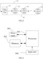
- FIG. 3 shows a schematic structural diagram of the electronic device according to some embodiments of the present disclosure.
- the electronic device may include components such as a processor 301 of one or more processing cores, a memory 302 of one or more computer-readable storage media, a power supply 303, and an input unit 304. It should be understood by those skilled in the art that the structure of the electronic device shown in FIG. 3 should be not constituted to be a limitation on the electronic device, and may include more or less components than illustrated, or may combine certain components, or different component arrangements.
- the processor 301 is a control center of the electronic device.
- the processor 601 is connected to various parts of the entire electronic device by various interfaces and lines, and performs various functions of the electronic device and processes data by running or executing software programs and/or modules stored in the memory 302 and invoking data stored in the memory 302, thereby monitoring the electronic device as a whole.
- the processor 301 may include one or more processing cores.
- the processor 301 may integrate an application processor and a modem processor, where the application processor mainly processes an operating system, a user interface, an application program, and the like, and the modem processor mainly processes wireless communication. It should be understood that the modulation/demodulation processor can be independent from the processor 301.
- the memory 302 may be used to store software programs and modules, and the processor 301 executes various functional applications and data processing by running the software programs and modules stored in the memory 302.
- the memory 302 may mainly include a storage program area and a storage data area, where the storage program area may store an operating system, an application program (such as a sound play function, an image play function, and the like) required by at least one function, and the like; and the storage data area may store data or the like created according to the use of the electronic device.
- memory 302 may include a high speed random access memory, and may also include a nonvolatile memory, such as at least one magnetic disk storage device, a flash memory device, or other volatile solid state storage device. Accordingly, memory 302 may also include a memory controller to provide access to the memory 302 by the processor 301.
- the electronic device further includes a power supply 303 for supplying power to the respective components.
- the power supply 303 may be logically connected to the processor 301 by the power supply management system, so that functions such as charging, discharging, and power consumption management are managed by the power supply management system.
- the power supply 303 may further include one or more direct current (DC)/or alternating current (AC) power sources, recharging system, power failure detection circuit, power converter or inverter, power supply status indicator, and the like.
- the electronic device may also include an input unit 304 operable to receive input numeric or character information and to generate a signal input of a keyboard, a mouse, a joystick, an optical or a trackball related to user settings and functional control.
- an input unit 304 operable to receive input numeric or character information and to generate a signal input of a keyboard, a mouse, a joystick, an optical or a trackball related to user settings and functional control.
- the electronic device may also include a display unit or the like, of which details are not repeatedly described herein.
- the processor 301 in the electronic device may load executable files corresponding to processes of one or more application programs into the memory 302 according to the following instructions, and the processor 301 executes the application programs stored in the memory 302 to implement various functions including:
- the storage medium may include a Read Only Memory (ROM), a Random Access Memory (RAM), a magnetic disk, an optical disk, or the like.
- the storage medium stores a computer program that is loaded by a processor to perform the method for encoding the battery management system provided in any of the embodiments of the present disclosure.
- the computer program may be loaded by the processor to perform the following steps:
- the inventors have found that the battery management system in the related art is encoded by a technician, and the battery management system has following problems: (1) when the number of the slave control boards of the BMS is larger, a time period for encoding the slave control boards is longer; and (2) it is necessary to count the number of slave control boards, which is prone to error.
- some embodiments of the present disclosure provide a battery management system: including a BMS master control board 401 and a plurality of BMS slave control boards 402, where the plurality of BMS slave control boards 402 are arranged in sequence; and a hard wire encoding line 404 connected between the BMS master control board 401 and a first BMS slave control board 402 of the plurality of BMS slave control boards 402, between the BMS master control board 401 and a last BMS slave control board 402 of the plurality of BMS slave control boards 402, and between any two adjacent ones of the plurality of BMS slave control boards 402; where the BMS master control board 401 is configured to transmit an encoding message to corresponding one of the BMS slave control boards 402 at a rear end of the hard wire encoding line via the CAN bus 403 when a digital signal of the hard wire encoding line received by the BMS master control board 401 is at a high level, and the BMS slave control board 40
- the BMS master control board 401 is connected to all the BMS slave control boards 402 via the CAN bus 403 for communication between the BMS master control board 401 and all the BMS slave control boards 402.
- the hard wire encoding line 404 is configured to transmit a digital signal between the BMS master control board 401 and the BMS slave control boards 402.
- the BMS master control board 401 is connected to the first BMS slave control board 402 via the hard wire encoding line 404, that is, a front end of the hard wire encoding line 404 is connected to the BMS master control board 401 and a rear end of the hard wire encoding line 404 is connected to the first BMS slave control board.
- Any two adjacent ones of the BMS slave control boards 402 are connected by the hard wire encoding line 404, that is, a front end of the hard wire encoding line 404 is connected to a previous BMS slave control board 401 and a rear end of the hard wire encoding line 404 is connected to a next BMS slave control board 402.
- the BMS master control board 401 is connected to the last BMS slave control board 402 via the hard wire encoding line 404, that is, a front end of the hard wire encoding line 404 is connected to the last BMS slave control board 402, and a rear end of the hard wire encoding line 404 is connected to the BMS master control board 401.
- the BMS master control board is configured to transmit an encoding message to corresponding one of the BMS slave control boards at the rear end of the hard wire encoding line via the CAN bus when a digital signal of the hard wire encoding line received by the BMS master control board is at a high level.
- the BMS slave control board is configured to receive the encoding message transmitted by the BMS master control board, so that encoding of all the BMS slave control boards 402 is automatically completed after the BMS master control board 401 transmits the encoding message to the last BMS slave control board 402, thereby realizing automatic encoding of each of the BMS slave control boards 402 by the BMS master control board 401.
- the battery management system may include: a BMS master control board 401 and a plurality of BMS slave control boards 402, where the BMS master control board 401 is connected with the plurality of BMS slave control boards 402 via the CAN bus 403 for communication connection between the BMS master control board and the BMS slave control boards; and a hard wire encoding line 404 connected between the BMS master control board 401 and a first BMS slave control board 402 of the plurality of BMS slave control boards 402, between the BMS master control board 401 and a last BMS slave control board 402 of the plurality of BMS slave control boards 402, and between any two adjacent ones of the plurality of BMS slave control boards 402, for a closed-loop connection between the BMS master control board and the BMS slave control boards.
- the BMS master control board is configured to transmit an encoding message to corresponding one of the BMS slave control boards at a rear end of the hard wire encoding line via the CAN bus when a digital signal received by the hard wire encoding line is at a high level (that is, the digital signal is 1), so that encoding of all the BMS slave control boards is completed automatically without counting the number of the BMS slave control boards after the BMS master control board transmits the encoding message to the last BMS slave control board.
- the BMS master control board includes a digital input interface and a digital output interface
- each of the BMS slave control boards includes a digital input interface and a digital output interface.
- the digital output interface of the BMS master control board is connected to the digital input interface of the first BMS slave control board via a hard wire encoding line.
- the digital output interface of the previous BMS slave control board is connected to the digital input interface of the next BMS slave control board via the hard wire encoding line.
- the digital output interface of the last BMS slave control board is connected to the digital input interface of the BMS master control board via a hard wire encoding line.
- the hard wire encoding line 404 includes a digital input interface DI1 and a digital output interface DO1
- the BMS master control board 401 includes a digital input interface DI2 and a digital output interface DO2
- each of the BMS slave control boards 402 includes a digital input interface DI3 and a digital output interface DO3
- the digital output interface DI2 of the BMS master control board 401 is connected to the digital input interface DI3 of the first BMS slave control board 402 via the digital output interface DO2 of the hard wire encoding line 404
- the digital output interface DO3 of the previous BMS slave control board 402 is connected to the digital input interface DI3 of the next BMS slave control board 402 via the digital output interface DO1 of the hard wire encoding line 404
- the digital output interface DO3 of the last BMS slave control board 402 is connected to the digital input interface DI2 of the BMS master control board 401 via the digital output interface DO1 of the hard wire
- the BMS master control board 401 is connected to the digital input interface DI3 of the BMS slave control board 402 via the hard wire encoding line 404
- the digital output interface DO3 of the first BMS slave control board 402 is connected to the digital input interface DI3 of the second BMS slave control board 402 via the digital output interface DO1 of the hard wire encoding line 404
- the digital output interface DO3 of the second BMS slave control board 402 is connected to the digital input interface DI3 of the third BMS slave control board 402 via the digital output interface DO1 of the hard wire encoding line 404, and so on.
- the digital output interface DO3 of the last BMS slave control board 402 is connected to the digital input interface DI2 of the BMS master control board 401 via the digital output interface DO1 of the hard wire encoding line 404.
- the closed-loop connection between the BMS master control board and the BMS slave control boards is realized through the hard wire encoding line and the CAN bus.
- the encoding message is transmitted to corresponding one of the BMS slave control boards at the rear end of the hard wire encoding line via the CAN bus, so that the BMS slave control board at the rear end of the hard wire encoding line is encoded.
- the intelligent encoding of all the BMS slave control boards is realized only through the digital input interface and the digital output interface of the hard wire encoding line, based on the digital input signal and the digital output signal and the message signal of the CAN bus.
- a process for encoding each of the BMS slave control boards by the BMS master control board is as follows: after the BMS master control board starts the process, the BMS master control board first outputs a high level to the first BMS slave control board via the hard wire encoding line and transmits an encoding message to the first BMS slave control board via the CAN bus; when the digital signal of the hard wire encoding line received by the first BMS slave control board is at a high level, the first BMS slave control board receives the encoding message, and completes the encoding of the first BMS slave control board; after the encoding of the first BMS slave control board ends, the first BMS slave control board outputs a high level to the second BMS slave control board via the hard wire encoding line, and the BMS master control board transmits the encoding message to the second BMS slave control board via the CAN bus; when the digital signal of the hard wire encoding line received by the second BMS slave control board is at a high level, the second BMS master control
- the BMS master control board is further configured to record the number of encoding messages and stop an encoding operation when the digital signal received from the digital input interface of the BMS master control board is at a high level.
- the digital signal received from the digital input interface of the BMS master control board is at a high level, it indicates that encoding of all the BMS slave control boards has been completed.
- the number of encoding messages that is, the number of BMS slave control boards, is recorded.
- the BMS master control board stops the encoding operation, so that the process for encoding the BMS slave control boards can be stopped, thereby realizing the intelligent encoding of all the BMS slave control boards.
- each of the BMS slave control boards is configured to receive an encoding messages transmitted by the BMS master control board.
- the BMS slave control board can automatically encode itself by receiving the encoding message transmitted by the BMS master control board, thereby improving the encoding efficiency of the BMS slave control board.
- the BMS master control board is further configured to differentiate the BMS slave control boards based on encoding messages received by the BMS slave control boards.
- each of the BMS slave control boards can complete encoding of the BMS slave control board after receiving the encoding message, so that the BMS slave control boards can be distinguished from each other.
- the BMS master control board is further configured to transmit, when a BMS slave control board is replaced, an encoding message to the replaced BMS slave control board via the CAN bus.
- the BMS master control board may transmit an encoding message to the replaced BMS slave control board via the CAN bus, thereby realizing automatic encoding of the replaced BMS slave control board.
- the BMS slave control panel is configured to collect a voltage and/or a temperature of a battery cell.
- the BMS slave control board is configured to collect a voltage and/or a temperature of a battery cell integrated on the BMS slave control board, and transmit the collected voltage and temperature of the battery cell to the BMS master control board.
- the BMS master control board is further configured to perform fault monitoring of one or more battery cells in each of the BMS slave control boards.
- the BMS master control board is further configured to perform fault monitoring according to the received voltage and/or temperature of the battery cells in the BMS slave control board, thereby improving the safety and reliability of the BMS.
- the battery management system includes: a BMS master control board 401 and a plurality of BMS slave control boards 402, where the BMS master control board 401 is connected with the plurality of BMS slave control boards 402 via the CAN bus 403 for communication connection between the BMS master control board and the BMS slave control boards; and a hard wire encoding line 404 connected between the BMS master control board 401 and the first BMS slave control board 402, between any two adjacent ones of the plurality of BMS slave control boards 402, and between the BMS master control board 401 and the last BMS slave control board 402, for a closed-loop connection between the BMS master control board and the BMS slave control boards.
- the BMS master control board 401 is configured to transmit an encoding message to corresponding one of the BMS slave control boards at a rear end of the hard wire encoding line via the CAN bus when a digital signal of the hard wire encoding line received by the BMS master control board is at a high level, so that encoding of all the BMS slave control boards is completed automatically without counting the number of the BMS slave control boards after the BMS master control board transmits the encoding message to the last BMS slave control board.
Landscapes
- Engineering & Computer Science (AREA)
- Theoretical Computer Science (AREA)
- Signal Processing (AREA)
- Computer Networks & Wireless Communication (AREA)
- Sustainable Development (AREA)
- Life Sciences & Earth Sciences (AREA)
- Physics & Mathematics (AREA)
- Sustainable Energy (AREA)
- Power Engineering (AREA)
- Transportation (AREA)
- Mechanical Engineering (AREA)
- General Physics & Mathematics (AREA)
- General Engineering & Computer Science (AREA)
- Charge And Discharge Circuits For Batteries Or The Like (AREA)
- Power Sources (AREA)
Abstract
Description
- The present disclosure relates to the field of battery technologies, and more particular to a method for encoding a battery management system and a device for encoding a battery management system.
- In a distributed two-stage architecture of a Battery management system (BMS) or a distributed three-stage architecture of the BMS, a master control board of the BMS is communicated with one or more slave control boards of the BMS via a serial bus interface such as a Controller Area Network (CAN) bus interface and a 485 bus interface, and the slave control boards of the BMS connected to the same bus is required to be distinguishable by the master control board of the BMS. Therefore, it is necessary to set different Identity Documents (IDs) for the slave control boards so as to encode the slave control boards of the BMS.
- In the related art, there are mainly three ways to encode the slave control boards of the BMS: a first way is to write an ID into each of the slave control boards of the BMS by a compiler or an upper computer to complete encoding of the slave control boards; a second way is to input an ID on each of the slave control boards of the BMS by setting a dial on the slave control board in factory or on-site assembling of the BMS to complete encoding of the slave control boards; and a third way is to count and set the number of slave control boards by the upper computer or the master control board of the BMS in on-site assembling of the BMS, so as to perform encoding of the slave control boards in a manner of the CAN communication and the hard wire digital signal transmission.
- However, there are following disadvantages in the three ways: when the number of the slave control boards of the BMS is larger, a time period for encoding the slave control boards is longer; for a case of replacing one of the slave control boards of the BMS, a technician is required to re-encode the slave control boards; and when the number of the slave control boards of the BMS cannot be counted or the number of the slave control boards is counted falsely, it is easy to cause failure of encoding the slave control boards and affect the encoding efficiency of the method for encoding the battery management system.
- In a first aspect, some embodiments of the present disclosure provides a method for encoding a battery management system, where the battery management system includes a master control board and a plurality of slave control boards, the master control board is connected with each of the slave control boards by a CAN bus, the plurality of slave control boards are arranged in sequence, and the master control board is connected to a first slave control board and a last slave control board of the plurality of slave control boards via an Input Output (IO) line, a previous slave control board and a next slave control board of the slave control boards are connected via the IO line, and a plurality of pieces of pre-configured encoding information are stored in the battery management system, and the method includes:
- performing addressing detection for each of the slave control boards to determine a detection result;
- the master control board transmitting an encoding message to the first slave control board via the CAN bus to obtain a digital signal output from the IO line when the detection result indicates that the slave control board is not addressed;
- the first slave control board receiving the encoding message if the digital signal is at a high level, to obtain encoding information from the encoding message and determine the encoding information as slave control encoding of the first slave control board;
- the first slave control board outputting a slave control board digital signal to the next slave control board via the IO line, and the master control board transmitting an encoding message to the next slave control board via the CAN bus;
- the next slave control board receiving the encoding message when it is detected that the slave control board digital signal is at a high level, to obtain encoding information from the encoding message and determine the encoding information as slave control encoding of the next slave control board; and
- returning to perform receiving of the encoding message when it is detected that the slave control board digital signal is at a high level, to obtain encoding information from the encoding message and determine the encoding information as slave control encoding of the next slave control board, until the digital signal of the IO line received by the master control board is at a high level, and obtain the slave control encoding of each of the slave control boards.
- In a second aspect, some embodiments of the present disclosure provides a device for encoding a battery management system, where the battery management system includes a master control board and a plurality of slave control boards, the master control board is connected with each of the slave control boards by a CAN bus, and the master control board is connected to a first slave control board and a last slave control board of the plurality of slave control boards via an Input Output (IO) line, a previous slave control board and a next slave control board of the slave control boards are connected via the IO line, and a plurality of pieces of pre-configured encoding information are stored in the battery management system, and the device includes:
- a detection module for performing addressing detection for each of the slave control boards to determine a detection result;
- a first transmission module for the master control board transmitting an encoding message to the first slave control board via the CAN bus to obtain a digital signal output from the IO line when the detection result indicates that the slave control board is not addressed;
- a reception module for the first slave control board receiving the encoding message if the digital signal is at a high level, to obtain encoding information from the encoding message and determine the encoding information as slave control encoding of the first slave control board;
- a second transmission module for the first slave control board outputting a slave control board digital signal to the next slave control board via the IO line, and the master control board transmitting encoding message to the next slave control board via the CAN bus;
- a determination module for the next slave control board receiving the encoding message when it is detected that the slave control board digital signal is at a high level, to obtain encoding information from the encoding message and determine the encoding information as slave control encoding of the next slave control board; and
- an obtaining module for returning to perform receiving of the encoding message when it is detected that the slave control board digital signal is at a high level, to obtain encoding information from the encoding message and determine the encoding information as slave control encoding of the next slave control board, until the digital signal of the IO line received by the master control board is at a high level, and obtain the slave control encoding of each of the slave control boards.
- In a third aspect, some embodiments of the present disclosure provide an electronic device, including: one or more processors; a memory; and one or more application programs, where the one or more application programs are stored in the memory and configured to be executed by the processors to implement any of the methods as described in the above first aspect.
- In a fourth aspect, some embodiments of the present disclosure further provide a computer readable storage medium having stored thereon a computer program that is loaded by a processor to perform any of the methods as described in the first aspect.
- In a fifth aspect, some embodiments of the present disclosure provide a battery management system, including: a BMS master control board and a plurality of BMS slave control boards, where the plurality of BMS slave control boards are arranged in sequence, the BMS master control board is connected to each of the plurality of BMS slave control boards via a CAN bus; and a hard wire encoding line connected between the BMS master control board and a first BMS slave control board of the plurality of BMS slave control boards, between the BMS master control board and a last BMS slave control board of the plurality of BMS slave control boards, and between any two adjacent ones of the plurality of BMS slave control boards; where the BMS master control board is configured to transmit an encoding message to corresponding one of the BMS slave control boards at a rear end of the hard wire encoding line via the CAN bus when a digital signal of the hard wire encoding line received by the BMS master control board is at a high level, and the BMS slave control board is configured to receive the encoding message transmitted by the BMS master control board.
- In a sixth aspect, some embodiments of the present disclosure provide a vehicle, including the battery management system of the fifth aspect.
- Beneficial Effects of the present disclosure are that:
in some embodiments of the present disclosure, the battery management system includes a master control board and a plurality of slave control boards, the master control board is connected with each of the slave control boards by a CAN bus, the plurality of slave control boards are arranged in sequence, and the master control board is connected to a first slave control board and a last slave control board of the plurality of slave control boards via an Input Output (IO) line, and a previous slave control board and a next slave control board of the slave control boards are connected via the IO line, so as to realize a closed-loop connection between the master control board and the slave control boards without counting the number of slave control boards in advance. Additionally, repetition of encoding of the slave control boards that have been addressed is avoided by performing addressing detection for each of the slave control boards. Further, the digital signal output from the IO line and the encoding message of the CAN bus are analyzed and processed, so that automatic encoding of all slave control boards in the battery management system is realized, the number of slave control boards does not need to be counted, missing encoding and re-coding are avoided, and the encoding efficiency of the battery management system is improved. -
-
FIG. 1 is a schematic flowchart of a method for encoding a battery management system according to some embodiments of the present disclosure. -
FIG. 2 is an architectural diagram of a battery management system according to some embodiments of the present disclosure. -
FIG. 3 is a schematic structural diagram of an electronic device according to some embodiments of the present disclosure. -
FIG. 4 is an architectural diagram of a battery management system according to some embodiments of the present disclosure. -
FIG. 5 is a schematic diagram of a connection relationship of a battery management system according to some embodiments of the present disclosure. - As shown in
FIG. 1 , which is a schematic flowchart of a method for encoding a battery management system according to some embodiments of the present disclosure. The battery management system may include a master control board and a plurality of slave control boards, where the master control board is connected with each of the slave control boards by a CAN bus, the plurality of slave control boards are arranged in sequence, and the master control board is connected to a first slave control board and a last slave control board of the plurality of slave control boards via an Input Output (IO) line, a previous slave control board and a next slave control board of the slave control boards are connected via the IO line, and a plurality of pieces of pre-configured encoding information are stored in the battery management system. The method for encoding the battery management system may include following steps S101-S106. - At step S101, addressing detection may be performed for each of the slave control boards to determine a detection result.
- The battery management system in the present embodiments includes a
master control board 101 and a plurality ofslave control boards 102, where the master control board is connected with each of the slave control boards through the CANbus 103 to realize communication connection between themaster control board 101 and each of theslave control boards 102, such as transmission and reception of a message. Themaster control board 101 is connected with the firstslave control board 102 and the lastslave control board 102 via an IOline 104 for transmission of a digital signal between themaster control board 101 and the firstslave control board 102 and between the lastslave control board 102 and themaster control board 101. The previousslave control board 102 and the nextslave control board 102 of the plurality ofslave control boards 102 are connected by the IOline 104 for transmission of a digital signal between two adjacentslave control boards 102. As shown inFIG. 2 , which is architectural diagram of a battery management system. In the present embodiments, a communication connection between themaster control board 101 and each of theslave control boards 102 is realized, and a closed-loop connection between themaster control board 101 and each of theslave control boards 102 is realized, so that the efficiency of encoding the slave control boards is improved without counting the number ofslave control boards 102 in advance. - A plurality of pieces of pre-configured encoding information may be stored in the battery management system, where the encoding information is pre-configured information for encoding the slave control boards. For example, the encoding information may be an identification, such as, a character, a number, or a combination of the character and the number. Illustratively, the pre-configured encoding information may be a board number, such as 1, 2, 3, ... 1000, or the like, and may be pre-configured and stored in a storage module of the battery management system.
- The addressing detection is a processing method for determining whether a current slave control board has been encoded, so as to avoid reducing of encoding efficiency by repetition encoding of the slave control boards.
- Specifically, efficient addressing detection of the slave control board can be realized by comparing a message transmitted or received by the battery management system with parameter information in an Electrically Erasable Programmable Read-Only Memory (EEPROM) of the slave control board and determining a detection result according to the comparison result.
- The performing of addressing detection for each of the slave control boards to obtain the detection result may include: configuring a slave control message corresponding to each of the slave control boards according to an internal parameter of the slave control board; obtaining a first check value by performing Cyclic Redundancy Check (CRC) check for the slave control message; obtaining a second check value by obtaining a master control message received by the master control board to perform CRC check for the master control message; and comparing the first check value with the second check value to determine a detection result.
- The CRC check refers to an algorithm for performing calculation of checksum on a frame of message. In the present embodiments, a CRC8 check algorithm is selected. The CRC8 is that a finally generated CRC check code is one byte, and generates a polynomial g(x)=x^8+x^5+x^4+1, which corresponds to g(x)=1·x^8+0·x^7+0·x^6+1·x^5+1·x^4+0·x^3+0·x^2+0·x^1+1·x^0, i.e., a binary number corresponding to the polynomial is 100110001.
- The first check value refers to a check value for the slave control board performing cyclic redundancy check for the slave control message configured according to the internal parameter of the slave control board. The second check value refers to a check value for the master control board performing cyclic redundancy check for the master control message received by the master control board. It should be noted that the first check value and the second check value use the same cyclic redundancy check algorithm, for example, the CRC8 check algorithm.
- Specifically, the slave control board reads the internal parameter of the slave control board after receiving a message for the addressing detection, and configures a slave control message according to the internal parameter. For example, the slave control board may use the internal parameter as the slave control message, and performs CRC check for the slave control message to obtain a first check value. At the same time, the master control board performs CRC check for a master control message received by the mater control board to obtain a second check value. By comparing the first check value with the second check value, i.e., comparing the first check value calculated by the slave control board itself with the second check value calculated by the master control board for the slave control board, addressing detection may be performed for the slave control board according to a comparison result between the first check value and the second check value. It can be understood in the present embodiments that, by comparing the CRC check value calculated by the slave control board itself with the CRC check value calculated by the master control board for the slave control board, the high efficiency of the CRC check calculation is utilized, and the addressing detection efficiency is improved.
- In one specific embodiment, after the battery management system is powered on and initialized, digital interfaces of the master control board and the slave control boards are initialized to be low levels (LOW). Then, each of the slave control boards enters a silent state, and the master control board transmits a frame of message (e.g., FlowControlReq=0xAA in 0x0801FF00) for check to the slave control board according to a preset period (e.g., 50ms). Then, the slave control board reads an internal parameter from itself and performs CRC8 calculation. A polynomial generated according to a CRC8 standard is x^8+x^5+x^4+1. After each of the slave control boards calculates respective CRC, a frame of CRC calculation result, that is, a first check value (e.g., CfgResp_Type=1 and CfgResp_Crc=CRC8 in 0x1827FExx) is returned to the master slave control board in a period of 50ms, and the master slave control board sequentially compares the first check value returned from each of the slave control boards with the second check value obtained by performing CRC8 calculation for the received master control message, and determines whether the slave control board is addressed.
- The comparing of the first check value with the second check value to determine the detection result may include: if the first check value is consistent with the second check value, the detection result indicates that the slave control board has been addressed; and if the first check value is inconsistent with the second check value, the detection result indicates that the slave control board is not addressed.
- Specifically, when the first check value is consistent with the second check value, it is indicated that the CRC check value calculated by the slave control board is the same as the CRC check value calculated by the master control board for the slave control board. Therefore, it is determined that the slave control board has been addressed, and encoding of the slave control board is not required. In this case, the master control board transmits an operation broadcast frame (for example, FlowControlReq=0x55 in 0x0801FF00, and stops transmitting the frame after continuously transmitting the frame for 2 seconds) on a periodic basis, and the battery management system enters a normal operation. When the first check value is inconsistent with the second check value, it is indicated that a first check value among the first check values calculated by the slave control boards is different from the CRC check value calculated by the master control board for the slave control boards, that is, at least one slave control board is not encoded. Therefore, it is determined that the slave control board is not addressed. As such, an addressing operation needs to be performed for the slave control boards to implement encoding processing of the slave control boards.
- The method may further include: before the configuring the slave control message corresponding to each of the slave control boards according to the internal parameter of the slave control board, transmitting a check message to the slave control board in a broadcast manner according to a preset period.
- The check message is an instruction for checking related information of the slave control board, such as a board number and an internal parameter.
- Specifically, the battery management system periodically transmits a check message to the slave control boards at a preset period, and the check message is in a broadcast form, so that each of the slave control boards receives the check message to avoid missed reception of the check message, thereby ensuring the check of the related information of the slave control board, and further improving the addressing detection efficiency of the slave control board.
- The method may further include: before the configuring the slave control message corresponding to each of the slave control boards according to the internal parameter of the slave control board, writing a configuration parameter into each of the slave control boards; and determining encoding information corresponding to the slave control board according to the configuration parameter.
- The configuration parameter is a parameter written into each of the slave control boards, and may be a board number, such as 1, 2, 3...; a number of channels; or a combination of the board number and the number of channels, which is not limited herein.
- Specifically, the battery management system writes the configuration parameter into the slave control board, and then processes the configuration parameter. The configuration parameter may be used as the encoding information, or the configuration parameter may be converted in a certain manner (for example, a constant value is added to the configuration parameter of each of the slave control boards) and used as the encoding information. It can be understood in the present embodiment that the encoding information is determined according to the configuration parameters by writing the configuration parameters into each of the slave control boards. Since the configuration information of each of the slave control boards is different, the written configuration parameter is different, which ensures the uniqueness of the encoding information by determining the encoding information based on the configuration parameters.
- At step S102, the master control board may transmit an encoding message to the first slave control board via the CAN bus to obtain a digital signal output from the IO line when the detection result indicates that the slave control board is not addressed.
- The encoding message refers to an instruction for encoding the slave control board.
- Specifically, when the slave control board is not addressed, encoding processing needs to be performed for the slave control board. Therefore, the master control board may transmit the encoding message to the first slave control board via the CAN bus to obtain a digital signal output from the IO line.
- The method may further include: after the master control board transmitting an encoding message to the first slave control board via the CAN bus to obtain a digital signal output from the IO line when the detection result indicates that the slave control board is not addressed, stopping transmitting the check message, and setting the digital signal of the IO line of the master control board to a high level.
- Specifically, when it is determined that the slave control board is not addressed, the slave control board needs to be encoded. Therefore, transmission of the check message is stopped without checking the related information of the slave control board while the digital signal of the IO line of the master control board is set to a high level, so that an encoding instruction may be triggered for the slave control board, thereby improving encoding efficiency.
- At
step S 103, the first slave control board may receive the encoding message if the digital signal is at a high level, to obtain encoding information from the encoding message and determine the encoding information as slave control encoding of the first slave control board. - The slave control encoding refers to encoding of the slave control board, and is used as an identification for distinguishing the slave control board.
- Specifically, when the digital signal output by the IO line is at a high level, the master control board may transmit the high level (where the digital signal is represented with 1) to the first slave control board via the IO line and transmit the encoding message via the CAN bus, and the first slave control board may receive the encoding message when the high level 1 output by the IO line and received by the first slave control board is valid and obtain encoding information from the battery management system, to use the encoding information as the slave control encoding of the first slave control board. Therefore, the encoding of the first slave control board is realized.
- In one specific embodiment, the IO line outputs a high level to a first slave control board connected to the IO line, and transmits an encoding message to the first slave control board. When the first slave control board connected to the IO line of the master control board detects that the IO line is at a high level, the first slave control board is in a state to be configured and receives the encoding message transmitted by the master control board to obtain and store encoding information into an internal EEPROM of the first slave control board. Then, the first slave control board returns a configuration completion flag (such as, CfgResp_Type=2) to the master control board, while the IO but connected to the first slave control board outputs a high level to the next slave control board, and configuration of the first slave control board code is completed.
- At
step S 104, the first slave control board may output a slave control board digital signal to the next slave control board via the IO line, and the master control board may transmit an encoding message to the next slave control board via the CAN bus. - Specifically, after the encoding of the first slave control board is completed, the first slave control board outputs a digital signal to the next slave control board (for example, the second slave control board) via the IO line, and the master control board transmits an encoding message via the CAN bus to implement encoding processing of the second slave control board.
- In one specific embodiment, the master control board transmits an encoding message of the next slave control board after receiving the configuration completion flag of the first slave control board.
- At step S105, the next slave control board may receive the encoding message when it is detected that the slave control board digital signal is at a high level, to obtain encoding information from the encoding message and determine the encoding information as slave control encoding of the next slave control board.
- Specifically, when the digital signal received by the slave control board is valid at the high level 1, the next slave control board receives an encoding message and obtains one piece of encoding information from the battery management system to use the encoding information as slave control encoding for the next slave control board, thereby completing the encoding of the next slave control board.
- In one specific embodiment, the next slave control board enters a configuration flow, receives and stores encoding information in the internal EEPROM of the next slave control board, and returns a configuration completion flag (CfgResp_Type=2) to the master control board. At the same time, the IO line connected to the next slave control board outputs a high level to a next slave control board, and encoding configuration of the next slave control board is completed.
- At step S106, performing receiving of the encoding message when it is detected that the slave control board digital signal is at a high level may be returned, to obtain encoding information from the encoding message and determine the encoding information as slave control encoding of the next slave control board, until the digital signal of the IO line received by the master control board is at a high level, and obtain the slave control encoding of each of the slave control boards.
- Specifically, after encoding of the current slave control board is completed, a next slave control board adjacent to the current slave control board continues to be encoded. Encoding of each of slave control boards can be realized by repeating step S105, until the digital signal of the IO line received by the master control board is at a high level. That is, the last slave control board outputs the high level 1 to the master control board via the IO line and the digital signal received by the master control board is valid at the high level 1. It indicates that the encoding of the last slave control board is completed, that is, the encoding processing of all slave control boards is realized. It can be understood in the embodiments that the digital signal output from the IO line and the encoding message of the CAN bus are analyzed and processed, so that automatic encoding of all slave control boards in the battery management system is realized, the number of slave control boards does not need to be counted, missing encoding and re-coding are avoided, and the encoding efficiency of the battery management system is improved.
- In a specific embodiment, configuration of the next slave control board is encoded in the encoding manner of step S105. When the last slave control board receives the encoding message, the last slave control board obtains and determines the encoding information as slave control encoding of the last slave control board, and returns a configuration completion flag (e.g., CfgResp_Type=2) to the master control board while outputting the digital signal to the master control board at a high level, and encoding of the last slave control board is completed.
- The method may further include: after obtaining the slave control encoding of each of the slave control boards, setting a digital signal of the IO line of the slave control board to a low level, and transmitting a normal communication message in a broadcast form.
- Specifically, after encoding of all of slave control boards is completed, the digital signal of the IO line of the slave control boards is set to a low level, and a normal communication message is transmitted in a broadcast form. All of slave control boards receive broadcast frames of the normal communication message of the master control board and are transferred from a silent state to an operation state, and transmit the normal communication message, so that the battery management system operates normally.
- If no encoding message is received from the slave control board within a preset time, it reminds that the slave control board is faulty.
- Specifically, if no coding message is received from the slave control board within a preset time, such as 2s, it reminds that the current slave control board is faulty, and encoding processing may be continued after the current slave control board is detected or replaced, thereby further improving encoding efficiency of the battery management system.
- In the present embodiments, the digital signal output from the IO line and the encoding message of the CAN bus are analyzed and processed, so that automatic encoding of all slave control boards in the battery management system is realized, the number of slave control boards does not need to be counted, missing encoding and re-coding are avoided, and the encoding efficiency of the battery management system is improved.
- Some embodiments of the present disclosure further provide an electronic device that integrates a device for encoding a battery management system provided in any of embodiments of the present disclosure, including:
- one or more processors;
- a memory; and
- one or more application programs, where the one or more application programs are stored in the memory and configured to be executed by the processors to implement any of the methods as described in the above embodiments.
- Embodiments of the present disclosure further provide an electronic device that integrates a device for encoding a battery management system provided in any of embodiments of the present disclosure. As shown in
FIG. 3 , which shows a schematic structural diagram of the electronic device according to some embodiments of the present disclosure. - The electronic device may include components such as a
processor 301 of one or more processing cores, amemory 302 of one or more computer-readable storage media, apower supply 303, and aninput unit 304. It should be understood by those skilled in the art that the structure of the electronic device shown inFIG. 3 should be not constituted to be a limitation on the electronic device, and may include more or less components than illustrated, or may combine certain components, or different component arrangements. - The
processor 301 is a control center of the electronic device. The processor 601 is connected to various parts of the entire electronic device by various interfaces and lines, and performs various functions of the electronic device and processes data by running or executing software programs and/or modules stored in thememory 302 and invoking data stored in thememory 302, thereby monitoring the electronic device as a whole. Alternatively, theprocessor 301 may include one or more processing cores. Preferably, theprocessor 301 may integrate an application processor and a modem processor, where the application processor mainly processes an operating system, a user interface, an application program, and the like, and the modem processor mainly processes wireless communication. It should be understood that the modulation/demodulation processor can be independent from theprocessor 301. - The
memory 302 may be used to store software programs and modules, and theprocessor 301 executes various functional applications and data processing by running the software programs and modules stored in thememory 302. Thememory 302 may mainly include a storage program area and a storage data area, where the storage program area may store an operating system, an application program (such as a sound play function, an image play function, and the like) required by at least one function, and the like; and the storage data area may store data or the like created according to the use of the electronic device. In addition,memory 302 may include a high speed random access memory, and may also include a nonvolatile memory, such as at least one magnetic disk storage device, a flash memory device, or other volatile solid state storage device. Accordingly,memory 302 may also include a memory controller to provide access to thememory 302 by theprocessor 301. - The electronic device further includes a
power supply 303 for supplying power to the respective components. Preferably, thepower supply 303 may be logically connected to theprocessor 301 by the power supply management system, so that functions such as charging, discharging, and power consumption management are managed by the power supply management system. Thepower supply 303 may further include one or more direct current (DC)/or alternating current (AC) power sources, recharging system, power failure detection circuit, power converter or inverter, power supply status indicator, and the like. - The electronic device may also include an
input unit 304 operable to receive input numeric or character information and to generate a signal input of a keyboard, a mouse, a joystick, an optical or a trackball related to user settings and functional control. - Although not shown, the electronic device may also include a display unit or the like, of which details are not repeatedly described herein. In the present embodiment, the
processor 301 in the electronic device may load executable files corresponding to processes of one or more application programs into thememory 302 according to the following instructions, and theprocessor 301 executes the application programs stored in thememory 302 to implement various functions including: - performing addressing detection for each of the slave control boards to determine a detection result;
- the master control board transmitting an encoding message to the first slave control board via the CAN bus to obtain a digital signal output from the IO line when the detection result indicates that the slave control board is not addressed;
- the first slave control board receiving the encoding message if the digital signal is at a high level, to obtain encoding information from the encoding message and determine the encoding information as slave control encoding of the first slave control board;
- the first slave control board outputting a slave control board digital signal to the next slave control board via the IO line, and the master control board transmitting an encoding message to the next slave control board via the CAN bus;
- the next slave control board receiving the encoding message when it is detected that the slave control board digital signal is at a high level, to obtain encoding information from the encoding message and determine the encoding information as slave control encoding of the next slave control board; and
- returning to perform receiving of the encoding message when it is detected that the slave control board digital signal is at a high level, to obtain encoding information from the encoding message and determine the encoding information as slave control encoding of the next slave control board, until the digital signal of the IO line received by the master control board is at a high level, and obtain the slave control encoding of each of the slave control boards.
- A person of ordinary skill in the art may understand that all or some of the steps in various methods of the foregoing embodiments may be implemented by program instructions, or may be implemented by a program instructing relevant hardware. The program instructions may be stored in a computer readable storage medium, and be loaded and executed by a processor.
- Some embodiments of the present disclosure further provide a computer readable storage medium. The storage medium may include a Read Only Memory (ROM), a Random Access Memory (RAM), a magnetic disk, an optical disk, or the like. The storage medium stores a computer program that is loaded by a processor to perform the method for encoding the battery management system provided in any of the embodiments of the present disclosure. For example, the computer program may be loaded by the processor to perform the following steps:
- performing addressing detection for each of the slave control boards to determine a detection result;
- the master control board transmitting an encoding message to the first slave control board via the CAN bus to obtain a digital signal output from the IO line when the detection result indicates that the slave control board is not addressed;
- the first slave control board receiving the encoding message if the digital signal is at a high level, to obtain encoding information from the encoding message and determine the encoding information as slave control encoding of the first slave control board;
- the first slave control board outputting a slave control board digital signal to the next slave control board via the IO line, and the master control board transmitting encoding message to the next slave control board via the CAN bus;
- the next slave control board receiving the encoding message when it is detected that the slave control board digital signal is at a high level, to obtain encoding information from the encoding message and determine the encoding information as slave control encoding of the next slave control board; and
- returning to perform receiving of the encoding message when it is detected that the slave control board digital signal is at a high level, to obtain encoding information from the encoding message and determine the encoding information as slave control encoding of the next slave control board, until the digital signal of the IO line received by the master control board is at a high level, and obtain the slave control encoding of each of the slave control boards.
- The inventors have found that the battery management system in the related art is encoded by a technician, and the battery management system has following problems: (1) when the number of the slave control boards of the BMS is larger, a time period for encoding the slave control boards is longer; and (2) it is necessary to count the number of slave control boards, which is prone to error.
- In order to solve the above problems, as shown in
FIG. 4 , some embodiments of the present disclosure provide a battery management system: including a BMSmaster control board 401 and a plurality of BMSslave control boards 402, where the plurality of BMSslave control boards 402 are arranged in sequence; and a hardwire encoding line 404 connected between the BMSmaster control board 401 and a first BMSslave control board 402 of the plurality of BMSslave control boards 402, between the BMSmaster control board 401 and a last BMSslave control board 402 of the plurality of BMSslave control boards 402, and between any two adjacent ones of the plurality of BMSslave control boards 402; where the BMSmaster control board 401 is configured to transmit an encoding message to corresponding one of the BMSslave control boards 402 at a rear end of the hard wire encoding line via theCAN bus 403 when a digital signal of the hard wire encoding line received by the BMSmaster control board 401 is at a high level, and the BMSslave control board 402 is configured to receive the encoding message transmitted by the BMSmaster control board 401. - The BMS
master control board 401 is connected to all the BMSslave control boards 402 via theCAN bus 403 for communication between the BMSmaster control board 401 and all the BMSslave control boards 402. - The hard
wire encoding line 404 is configured to transmit a digital signal between the BMSmaster control board 401 and the BMSslave control boards 402. - Specifically, the BMS
master control board 401 is connected to the first BMSslave control board 402 via the hardwire encoding line 404, that is, a front end of the hardwire encoding line 404 is connected to the BMSmaster control board 401 and a rear end of the hardwire encoding line 404 is connected to the first BMS slave control board. Any two adjacent ones of the BMSslave control boards 402 are connected by the hardwire encoding line 404, that is, a front end of the hardwire encoding line 404 is connected to a previous BMSslave control board 401 and a rear end of the hardwire encoding line 404 is connected to a next BMSslave control board 402. The BMSmaster control board 401 is connected to the last BMSslave control board 402 via the hardwire encoding line 404, that is, a front end of the hardwire encoding line 404 is connected to the last BMSslave control board 402, and a rear end of the hardwire encoding line 404 is connected to the BMSmaster control board 401. As such, a closed-loop connection between the BMS master control board and the BMS slave control boards is realized. The BMS master control board is configured to transmit an encoding message to corresponding one of the BMS slave control boards at the rear end of the hard wire encoding line via the CAN bus when a digital signal of the hard wire encoding line received by the BMS master control board is at a high level. The BMS slave control board is configured to receive the encoding message transmitted by the BMS master control board, so that encoding of all the BMSslave control boards 402 is automatically completed after the BMSmaster control board 401 transmits the encoding message to the last BMSslave control board 402, thereby realizing automatic encoding of each of the BMSslave control boards 402 by the BMSmaster control board 401. - The battery management system provided in some embodiments of the present disclosure may include: a BMS
master control board 401 and a plurality of BMSslave control boards 402, where the BMSmaster control board 401 is connected with the plurality of BMSslave control boards 402 via theCAN bus 403 for communication connection between the BMS master control board and the BMS slave control boards; and a hardwire encoding line 404 connected between the BMSmaster control board 401 and a first BMSslave control board 402 of the plurality of BMSslave control boards 402, between the BMSmaster control board 401 and a last BMSslave control board 402 of the plurality of BMSslave control boards 402, and between any two adjacent ones of the plurality of BMSslave control boards 402, for a closed-loop connection between the BMS master control board and the BMS slave control boards. The BMS master control board is configured to transmit an encoding message to corresponding one of the BMS slave control boards at a rear end of the hard wire encoding line via the CAN bus when a digital signal received by the hard wire encoding line is at a high level (that is, the digital signal is 1), so that encoding of all the BMS slave control boards is completed automatically without counting the number of the BMS slave control boards after the BMS master control board transmits the encoding message to the last BMS slave control board. When the BMS slave control board is replaced, encoding of all the BMS slave control boards is performed automatically, which improves board encoding efficiency of the BMS slave control boards, and realizes the intelligent encoding of all the BMS slave control boards through a mechanism of the hard wire encoding line. - In some embodiments, the BMS master control board includes a digital input interface and a digital output interface, and each of the BMS slave control boards includes a digital input interface and a digital output interface. The digital output interface of the BMS master control board is connected to the digital input interface of the first BMS slave control board via a hard wire encoding line. The digital output interface of the previous BMS slave control board is connected to the digital input interface of the next BMS slave control board via the hard wire encoding line. The digital output interface of the last BMS slave control board is connected to the digital input interface of the BMS master control board via a hard wire encoding line.
- Specifically, as shown in
FIG. 5 , which is a schematic diagram of a connection relationship of a battery management system. The hardwire encoding line 404 includes a digital input interface DI1 and a digital output interface DO1, the BMSmaster control board 401 includes a digital input interface DI2 and a digital output interface DO2, each of the BMSslave control boards 402 includes a digital input interface DI3 and a digital output interface DO3, the digital output interface DI2 of the BMSmaster control board 401 is connected to the digital input interface DI3 of the first BMSslave control board 402 via the digital output interface DO2 of the hardwire encoding line 404, the digital output interface DO3 of the previous BMSslave control board 402 is connected to the digital input interface DI3 of the next BMSslave control board 402 via the digital output interface DO1 of the hardwire encoding line 404, and the digital output interface DO3 of the last BMSslave control board 402 is connected to the digital input interface DI2 of the BMSmaster control board 401 via the digital output interface DO1 of the hardwire encoding line 404. That is, the BMSmaster control board 401 is connected to the digital input interface DI3 of the BMSslave control board 402 via the hardwire encoding line 404, the digital output interface DO3 of the first BMSslave control board 402 is connected to the digital input interface DI3 of the second BMSslave control board 402 via the digital output interface DO1 of the hardwire encoding line 404, the digital output interface DO3 of the second BMSslave control board 402 is connected to the digital input interface DI3 of the third BMSslave control board 402 via the digital output interface DO1 of the hardwire encoding line 404, and so on. The digital output interface DO3 of the last BMSslave control board 402 is connected to the digital input interface DI2 of the BMSmaster control board 401 via the digital output interface DO1 of the hardwire encoding line 404. The closed-loop connection between the BMS master control board and the BMS slave control boards is realized through the hard wire encoding line and the CAN bus. When the digital signal of the hard wire encoding line received by the BMS master control board is at a high level, the encoding message is transmitted to corresponding one of the BMS slave control boards at the rear end of the hard wire encoding line via the CAN bus, so that the BMS slave control board at the rear end of the hard wire encoding line is encoded. As such, it is not necessary to count the number of the BMS slave control boards, and the intelligent encoding of all the BMS slave control boards is realized only through the digital input interface and the digital output interface of the hard wire encoding line, based on the digital input signal and the digital output signal and the message signal of the CAN bus. - In one example, a process for encoding each of the BMS slave control boards by the BMS master control board is as follows: after the BMS master control board starts the process, the BMS master control board first outputs a high level to the first BMS slave control board via the hard wire encoding line and transmits an encoding message to the first BMS slave control board via the CAN bus; when the digital signal of the hard wire encoding line received by the first BMS slave control board is at a high level, the first BMS slave control board receives the encoding message, and completes the encoding of the first BMS slave control board; after the encoding of the first BMS slave control board ends, the first BMS slave control board outputs a high level to the second BMS slave control board via the hard wire encoding line, and the BMS master control board transmits the encoding message to the second BMS slave control board via the CAN bus; when the digital signal of the hard wire encoding line received by the second BMS slave control board is at a high level, the second BMS slave control board receives the encoding message, and completes the encoding of the second BMS slave control board, and so on, until the encoding of the last BMS slave control board is completed; after the encoding of the last BMS slave control board is completed, the last BMS slave control board outputs a high level to the BMS master control board via the hard wire encoding line; and when the digital signal of the hard wire encoding line received by the BMS master control board is at a high level, the process ends, thereby automatically completing automatic encoding of all the BMS slave control boards.
- In some embodiments, the BMS master control board is further configured to record the number of encoding messages and stop an encoding operation when the digital signal received from the digital input interface of the BMS master control board is at a high level.
- Specifically, when the digital signal received from the digital input interface of the BMS master control board is at a high level, it indicates that encoding of all the BMS slave control boards has been completed. In this case, the number of encoding messages, that is, the number of BMS slave control boards, is recorded. At the same time, the BMS master control board stops the encoding operation, so that the process for encoding the BMS slave control boards can be stopped, thereby realizing the intelligent encoding of all the BMS slave control boards.
- In some embodiments, each of the BMS slave control boards is configured to receive an encoding messages transmitted by the BMS master control board.
- Specifically, the BMS slave control board can automatically encode itself by receiving the encoding message transmitted by the BMS master control board, thereby improving the encoding efficiency of the BMS slave control board.
- In some embodiments, the BMS master control board is further configured to differentiate the BMS slave control boards based on encoding messages received by the BMS slave control boards.
- Specifically, each of the BMS slave control boards can complete encoding of the BMS slave control board after receiving the encoding message, so that the BMS slave control boards can be distinguished from each other.
- In some embodiments, the BMS master control board is further configured to transmit, when a BMS slave control board is replaced, an encoding message to the replaced BMS slave control board via the CAN bus.
- Specifically, for the replaced BMS slave control board, the BMS master control board may transmit an encoding message to the replaced BMS slave control board via the CAN bus, thereby realizing automatic encoding of the replaced BMS slave control board.
- In some embodiments, the BMS slave control panel is configured to collect a voltage and/or a temperature of a battery cell.
- Specifically, the BMS slave control board is configured to collect a voltage and/or a temperature of a battery cell integrated on the BMS slave control board, and transmit the collected voltage and temperature of the battery cell to the BMS master control board.
- In some embodiments, the BMS master control board is further configured to perform fault monitoring of one or more battery cells in each of the BMS slave control boards.
- Specifically, the BMS master control board is further configured to perform fault monitoring according to the received voltage and/or temperature of the battery cells in the BMS slave control board, thereby improving the safety and reliability of the BMS.
- Some embodiments of the present disclosure further provide a vehicle: including any of the battery management systems described above. The battery management system includes: a BMS
master control board 401 and a plurality of BMSslave control boards 402, where the BMSmaster control board 401 is connected with the plurality of BMSslave control boards 402 via theCAN bus 403 for communication connection between the BMS master control board and the BMS slave control boards; and a hardwire encoding line 404 connected between the BMSmaster control board 401 and the first BMSslave control board 402, between any two adjacent ones of the plurality of BMSslave control boards 402, and between the BMSmaster control board 401 and the last BMSslave control board 402, for a closed-loop connection between the BMS master control board and the BMS slave control boards. The BMSmaster control board 401 is configured to transmit an encoding message to corresponding one of the BMS slave control boards at a rear end of the hard wire encoding line via the CAN bus when a digital signal of the hard wire encoding line received by the BMS master control board is at a high level, so that encoding of all the BMS slave control boards is completed automatically without counting the number of the BMS slave control boards after the BMS master control board transmits the encoding message to the last BMS slave control board. When the BMS slave control board is replaced, encoding of all the BMS slave control boards is performed automatically, which improves board encoding efficiency of the BMS slave control boards, and realizes the intelligent encoding of all the BMS slave control boards through a mechanism of the hard wire encoding line and further improves the management efficiency of the battery management system.
Claims (15)
- A method for encoding a battery management system, wherein the battery management system comprises a master control board and a plurality of slave control boards, the master control board is connected with each of the slave control boards by a Controller Area Network (CAN) bus, the plurality of slave control boards are arranged in sequence, and the master control board is connected to a first slave control board and a last slave control board of the plurality of slave control boards via an Input Output (IO) line, a previous slave control board and a next slave control board of the plurality of slave control boards are connected via the IO line, and a plurality of pieces of pre-configured encoding information are stored in the battery management system, and the method comprises:performing addressing detection for each of the plurality of slave control boards to determine a detection result;the master control board transmitting, in responsive to the detection result indicating that the slave control board is not addressed, an encoding message to the first slave control board via the CAN bus to obtain a digital signal output from the IO line;the first slave control board receiving the encoding message in responsive to the digital signal being at a high level, to obtain encoding information from the encoding message and determine the encoding information as slave control encoding of the first slave control board;the first slave control board outputting a slave control board digital signal to a next slave control board via the IO line, and the master control board transmitting an encoding message to the next slave control board via the CAN bus;the next slave control board receiving the encoding message in responsive to the slave control board digital signal being at a high level, to obtain encoding information from the encoding message and determine the encoding information as slave control encoding of the next slave control board; andreturning to perform receiving an encoding message by a next slave control in responsive to the slave control board digital signal being at a high level, to obtain encoding information from the encoding message and determine the encoding information as slave control encoding of the next slave control board, until the digital signal of the IO line received by the master control board is at a high level, and obtain the slave control encoding of each of the slave control boards.
- The method of claim 1, wherein the performing of addressing detection for each of the plurality of slave control boards comprises:configuring a slave control message corresponding to each of the slave control boards based on an internal parameter of the slave control board;obtaining a first check value by performing Cyclic Redundancy Check (CRC) check for the slave control message;obtaining a second check value by obtaining a master control message received by the master control board to perform CRC check for the master control message; andcomparing the first check value with the second check value to determine the detection result.
- The method of claim 2, wherein the comparing of the first check value with the second check value comprises:determining that the detection result indicates that the slave control board has been addressed in responsive to the first check value being consistent with the second check value; anddetermining that the detection result indicates that the slave control board is not addressed in responsive to the first check value being inconsistent with the second check value.
- The method of claim 2, further comprising: before configuring the slave control message corresponding to each of the slave control boards based on the internal parameter of the slave control board,writing a configuration parameter into each of the slave control boards; anddetermining encoding information corresponding to the slave control board based on the configuration parameter.
- The method of claim 2, further comprising: before configuring the slave control message corresponding to each of the slave control boards based on the internal parameter of the slave control board,
transmitting a check message to the slave control board in a broadcast manner according to a preset period. - The method of claim 5, further comprising: after the master control board transmitting the encoding message to the first slave control board via the CAN bus,
stopping transmitting the check message, and setting the digital signal of the IO line of the master control board to a high level. - The method of any one of claims 1-6, further comprising: after the obtaining of the slave control encoding of each of the slave control boards,
setting a digital signal of the IO line of the slave control board to a low level, and transmitting a normal communication message in a broadcast form. - The method of any one of claims 1-6, further comprising:
reminding that the slave control board is faulty in responsive to no encoding message being received from the slave control board within a preset time. - An electronic device, comprising:one or more processors;a memory; andone or more application programs, wherein the one or more application programs are stored in the memory and configured to be executed by the processors to implement the method of any one of claims 1-8.
- A computer readable storage medium having stored thereon a computer program that is loaded by a processor to perform the method of any one of claims 1-8.
- A battery management system (BMS), comprising:a BMS master control board and a plurality of BMS slave control boards, wherein the plurality of BMS slave control boards are arranged in sequence, and the BMS master control board is connected to each of the plurality of BMS slave control boards via a Controller Area Network (CAN) bus; anda hard wire encoding line connected between the BMS master control board and a first BMS slave control board of the plurality of BMS slave control boards, between the BMS master control board and a last BMS slave control board of the plurality of BMS slave control boards, and between any two adjacent ones of the plurality of BMS slave control boards;wherein the BMS master control board is configured to transmit an encoding message to corresponding one of the BMS slave control boards at a rear end of the hard wire encoding line via the CAN bus in responsive to a digital signal of the hard wire encoding line received by the BMS master control board being at a high level; andwherein the BMS slave control board is configured to receive the encoding message transmitted by the BMS master control board.
- The battery management system of claim 11, wherein the BMS master control board comprises a digital input interface and a digital output interface, and each of the BMS slave control boards comprises a digital input interface and a digital output interface;the digital output interface of the BMS master control board is connected to the digital input interface of the first BMS slave control board via the hard wire encoding line;the digital output interface of a previous BMS slave control board of the plurality of BMS slave control boards is connected to the digital input interface of a next BMS slave control board of the plurality of BMS slave control boards via the hard wire encoding line; andthe digital output interface of the last BMS slave control board is connected to the digital input interface of the BMS master control board via the hard wire encoding line.
- The battery management system of claim 12, wherein the BMS master control board is further configured to record a number of encoding messages and stop an encoding operation in responsive to the digital signal received from the digital input interface of the BMS master control board being at a high level.
- The battery management system of claim 11, wherein the BMS master control board is further configured to perform at least one of: differentiating the BMS slave control boards based on encoding messages received by the BMS slave control boards, transmitting, in responsive to a BMS slave control board being replaced, an encoding message to the replaced BMS slave control board via the CAN bus, performing fault monitoring of one or more battery cells in each of the BMS slave control boards, or writing a configuration parameter into each of the slave control boards; or
wherein the BMS slave control panel is configured to collect at least one of a voltage or a temperature of a battery cell. - A vehicle, comprising: the battery management system of any one of claims 11-14.
Applications Claiming Priority (3)
| Application Number | Priority Date | Filing Date | Title |
|---|---|---|---|
| CN202321375952.2U CN219904120U (en) | 2023-05-31 | 2023-05-31 | Battery management system and vehicle |
| CN202310641208.0A CN116679818A (en) | 2023-05-31 | 2023-05-31 | Encoding method, electronic equipment and storage medium of battery management system |
| PCT/CN2024/093938 WO2024245010A1 (en) | 2023-05-31 | 2024-05-17 | Encoding method for battery management system, and related device |
Publications (2)
| Publication Number | Publication Date |
|---|---|
| EP4472148A1 true EP4472148A1 (en) | 2024-12-04 |
| EP4472148B1 EP4472148B1 (en) | 2026-07-15 |
Family
ID=93656640
Family Applications (1)
| Application Number | Title | Priority Date | Filing Date |
|---|---|---|---|
| EP24179241.5A Active EP4472148B1 (en) | 2023-05-31 | 2024-05-31 | Method and device for encoding battery management system |
Country Status (2)
| Country | Link |
|---|---|
| EP (1) | EP4472148B1 (en) |
| WO (1) | WO2024245010A1 (en) |
Citations (3)
| Publication number | Priority date | Publication date | Assignee | Title |
|---|---|---|---|---|
| US20170106764A1 (en) * | 2015-10-15 | 2017-04-20 | Powin Energy Corporation | Battery-assisted electric vehicle charging system and method |
| US20210376635A1 (en) * | 2020-06-02 | 2021-12-02 | Inergy Holdings, LLC | Stackable battery charging and power output slices |
| US20220046114A1 (en) * | 2019-01-20 | 2022-02-10 | Arilou Information Security Technologies Ltd. | System and method for data compression based on data position in frames structure |
Family Cites Families (8)
| Publication number | Priority date | Publication date | Assignee | Title |
|---|---|---|---|---|
| CN104486180B (en) * | 2014-11-11 | 2019-03-12 | 惠州市亿能电子有限公司 | A kind of BMS distributes the method from control unit ID automatically |
| CN106300493B (en) * | 2015-06-26 | 2019-04-19 | 北京宝沃汽车有限公司 | Management system, control method and the vehicle of power battery |
| CN107766271A (en) * | 2016-08-16 | 2018-03-06 | 浙江高泰昊能科技有限公司 | BMS addresses on electric automobile are from distribution system |
| CN107508930A (en) * | 2017-09-15 | 2017-12-22 | 上海炙云新能源科技有限公司 | ID distribution methods and system |
| KR102337858B1 (en) * | 2018-01-19 | 2021-12-08 | 주식회사 엘지에너지솔루션 | Apparatus for reprogramming application |
| CN114115177A (en) * | 2021-11-09 | 2022-03-01 | 联合汽车电子有限公司 | Multi-controller system and its coding method |
| CN219904120U (en) * | 2023-05-31 | 2023-10-27 | 惠州亿纬锂能股份有限公司 | Battery management system and vehicle |
| CN116679818A (en) * | 2023-05-31 | 2023-09-01 | 惠州亿纬锂能股份有限公司 | Encoding method, electronic equipment and storage medium of battery management system |
-
2024
- 2024-05-17 WO PCT/CN2024/093938 patent/WO2024245010A1/en not_active Ceased
- 2024-05-31 EP EP24179241.5A patent/EP4472148B1/en active Active
Patent Citations (3)
| Publication number | Priority date | Publication date | Assignee | Title |
|---|---|---|---|---|
| US20170106764A1 (en) * | 2015-10-15 | 2017-04-20 | Powin Energy Corporation | Battery-assisted electric vehicle charging system and method |
| US20220046114A1 (en) * | 2019-01-20 | 2022-02-10 | Arilou Information Security Technologies Ltd. | System and method for data compression based on data position in frames structure |
| US20210376635A1 (en) * | 2020-06-02 | 2021-12-02 | Inergy Holdings, LLC | Stackable battery charging and power output slices |
Also Published As
| Publication number | Publication date |
|---|---|
| EP4472148B1 (en) | 2026-07-15 |
| WO2024245010A1 (en) | 2024-12-05 |
Similar Documents
| Publication | Publication Date | Title |
|---|---|---|
| CN104216499B (en) | Rack and its power control method | |
| CN116679818A (en) | Encoding method, electronic equipment and storage medium of battery management system | |
| CN111104356B (en) | Automatic addressing method and system for multiple slave control modules | |
| CN112822002B (en) | SPI-based communication method and device, electronic equipment and storage medium | |
| CN112637011B (en) | Data transmission method, data transmission device, and storage medium | |
| CN114537156A (en) | Controller framework and electric automobile | |
| US7827335B2 (en) | Remote communication system of a network | |
| CN119256301A (en) | Multi-controller system, encoding method, electronic device and storage medium | |
| CN111509308A (en) | Control method, device and system for coding of daughter board of battery management system | |
| CN106708759B (en) | Method for controlling digital input/output interface and processor | |
| CN112636762A (en) | Battery management system, slave control encoding method and device | |
| CN117768380B (en) | Data processing method, device, system, electronic equipment and readable storage medium | |
| WO2024245010A1 (en) | Encoding method for battery management system, and related device | |
| CN111104357B (en) | Automatic addressing method and device for multiple slave control modules | |
| CN116946047A (en) | Vehicle control method and device and vehicle | |
| CN108415403B (en) | A safety processing method for computer interlocking data acquisition control | |
| CN113485284B (en) | Message data processing method, device, equipment and storage medium | |
| EP4375964A1 (en) | Fire alarm device and system | |
| CN220290885U (en) | Battery management module and battery management device | |
| CN119675652B (en) | State recovery circuits, methods, apparatuses, electronic devices and storage media thereof | |
| CN223182133U (en) | Automatic coding system | |
| US20260104465A1 (en) | Battery management system, encoding method for battery management system, and electronic device | |
| CN120630944A (en) | Parameter calibration method, device, equipment and storage medium | |
| CN119094631B (en) | Protocol self-adaption method, device and equipment of electric energy meter and storage medium | |
| CN120956559A (en) | A method and system for adaptive switching of daisy chain communication links |
Legal Events
| Date | Code | Title | Description |
|---|---|---|---|
| PUAI | Public reference made under article 153(3) epc to a published international application that has entered the european phase |
Free format text: ORIGINAL CODE: 0009012 |
|
| STAA | Information on the status of an ep patent application or granted ep patent |
Free format text: STATUS: REQUEST FOR EXAMINATION WAS MADE |
|
| 17P | Request for examination filed |
Effective date: 20240531 |
|
| AK | Designated contracting states |
Kind code of ref document: A1 Designated state(s): AL AT BE BG CH CY CZ DE DK EE ES FI FR GB GR HR HU IE IS IT LI LT LU LV MC ME MK MT NL NO PL PT RO RS SE SI SK SM TR |
|
| GRAP | Despatch of communication of intention to grant a patent |
Free format text: ORIGINAL CODE: EPIDOSNIGR1 |
|
| STAA | Information on the status of an ep patent application or granted ep patent |
Free format text: STATUS: GRANT OF PATENT IS INTENDED |
|
| INTG | Intention to grant announced |
Effective date: 20260210 |
|
| RIC1 | Information provided on ipc code assigned before grant |
Ipc: H04L 12/40 20060101AFI20260203BHEP |
|
| GRAS | Grant fee paid |
Free format text: ORIGINAL CODE: EPIDOSNIGR3 |
|
| GRAA | (expected) grant |
Free format text: ORIGINAL CODE: 0009210 |
|
| STAA | Information on the status of an ep patent application or granted ep patent |
Free format text: STATUS: THE PATENT HAS BEEN GRANTED |
|
| AK | Designated contracting states |
Kind code of ref document: B1 Designated state(s): AL AT BE BG CH CY CZ DE DK EE ES FI FR GB GR HR HU IE IS IT LI LT LU LV MC ME MK MT NL NO PL PT RO RS SE SI SK SM TR |
|
| P01 | Opt-out of the competence of the unified patent court (upc) registered |
Free format text: CASE NUMBER: UPC_APP_0017608_4472148/2026 Effective date: 20260608 |
|
| REG | Reference to a national code |
Ref country code: CH Ref legal event code: F10 Free format text: ST27 STATUS EVENT CODE: U-0-0-F10-F00 (AS PROVIDED BY THE NATIONAL OFFICE) Effective date: 20260715 Ref country code: GB Ref legal event code: FG4D |
|
| REG | Reference to a national code |
Ref country code: DE Ref legal event code: R096 Ref document number: 602024006112 Country of ref document: DE |
|
| REG | Reference to a national code |
Ref country code: IE Ref legal event code: FG4D |