EP4471968A1 - Stromschiene, stromschienenanordnung und batteriepack - Google Patents
Stromschiene, stromschienenanordnung und batteriepack Download PDFInfo
- Publication number
- EP4471968A1 EP4471968A1 EP23213579.8A EP23213579A EP4471968A1 EP 4471968 A1 EP4471968 A1 EP 4471968A1 EP 23213579 A EP23213579 A EP 23213579A EP 4471968 A1 EP4471968 A1 EP 4471968A1
- Authority
- EP
- European Patent Office
- Prior art keywords
- bar
- negative electrode
- positive electrode
- electrode portion
- bus bar
- Prior art date
- Legal status (The legal status is an assumption and is not a legal conclusion. Google has not performed a legal analysis and makes no representation as to the accuracy of the status listed.)
- Pending
Links
- 239000003292 glue Substances 0.000 claims abstract description 100
- 238000002347 injection Methods 0.000 claims abstract description 56
- 239000007924 injection Substances 0.000 claims abstract description 56
- 230000000712 assembly Effects 0.000 claims description 7
- 238000000429 assembly Methods 0.000 claims description 7
- 239000004033 plastic Substances 0.000 claims description 6
- RYGMFSIKBFXOCR-UHFFFAOYSA-N Copper Chemical compound [Cu] RYGMFSIKBFXOCR-UHFFFAOYSA-N 0.000 claims description 5
- 229910052802 copper Inorganic materials 0.000 claims description 5
- 239000010949 copper Substances 0.000 claims description 5
- XAGFODPZIPBFFR-UHFFFAOYSA-N aluminium Chemical compound [Al] XAGFODPZIPBFFR-UHFFFAOYSA-N 0.000 claims description 4
- 229910052782 aluminium Inorganic materials 0.000 claims description 4
- 238000005452 bending Methods 0.000 claims description 4
- 239000006260 foam Substances 0.000 description 31
- 238000005187 foaming Methods 0.000 description 6
- 239000000243 solution Substances 0.000 description 5
- 238000009413 insulation Methods 0.000 description 4
- 238000000034 method Methods 0.000 description 4
- 238000003466 welding Methods 0.000 description 4
- PXHVJJICTQNCMI-UHFFFAOYSA-N Nickel Chemical compound [Ni] PXHVJJICTQNCMI-UHFFFAOYSA-N 0.000 description 2
- 238000010586 diagram Methods 0.000 description 2
- 230000000694 effects Effects 0.000 description 2
- 238000004519 manufacturing process Methods 0.000 description 2
- 230000013011 mating Effects 0.000 description 2
- 230000009286 beneficial effect Effects 0.000 description 1
- 230000017525 heat dissipation Effects 0.000 description 1
- 238000012986 modification Methods 0.000 description 1
- 230000004048 modification Effects 0.000 description 1
- 229910052759 nickel Inorganic materials 0.000 description 1
- 239000002985 plastic film Substances 0.000 description 1
- 238000003825 pressing Methods 0.000 description 1
Images




Classifications
-
- H—ELECTRICITY
- H01—ELECTRIC ELEMENTS
- H01M—PROCESSES OR MEANS, e.g. BATTERIES, FOR THE DIRECT CONVERSION OF CHEMICAL ENERGY INTO ELECTRICAL ENERGY
- H01M50/00—Constructional details or processes of manufacture of the non-active parts of electrochemical cells other than fuel cells, e.g. hybrid cells
- H01M50/20—Mountings; Secondary casings or frames; Racks, modules or packs; Suspension devices; Shock absorbers; Transport or carrying devices; Holders
- H01M50/204—Racks, modules or packs for multiple batteries or multiple cells
- H01M50/207—Racks, modules or packs for multiple batteries or multiple cells characterised by their shape
- H01M50/213—Racks, modules or packs for multiple batteries or multiple cells characterised by their shape adapted for cells having curved cross-section, e.g. round or elliptic
-
- H—ELECTRICITY
- H01—ELECTRIC ELEMENTS
- H01M—PROCESSES OR MEANS, e.g. BATTERIES, FOR THE DIRECT CONVERSION OF CHEMICAL ENERGY INTO ELECTRICAL ENERGY
- H01M50/00—Constructional details or processes of manufacture of the non-active parts of electrochemical cells other than fuel cells, e.g. hybrid cells
- H01M50/50—Current conducting connections for cells or batteries
- H01M50/502—Interconnectors for connecting terminals of adjacent batteries; Interconnectors for connecting cells outside a battery casing
- H01M50/503—Interconnectors for connecting terminals of adjacent batteries; Interconnectors for connecting cells outside a battery casing characterised by the shape of the interconnectors
-
- H—ELECTRICITY
- H01—ELECTRIC ELEMENTS
- H01M—PROCESSES OR MEANS, e.g. BATTERIES, FOR THE DIRECT CONVERSION OF CHEMICAL ENERGY INTO ELECTRICAL ENERGY
- H01M50/00—Constructional details or processes of manufacture of the non-active parts of electrochemical cells other than fuel cells, e.g. hybrid cells
- H01M50/50—Current conducting connections for cells or batteries
- H01M50/502—Interconnectors for connecting terminals of adjacent batteries; Interconnectors for connecting cells outside a battery casing
- H01M50/505—Interconnectors for connecting terminals of adjacent batteries; Interconnectors for connecting cells outside a battery casing comprising a single busbar
-
- H—ELECTRICITY
- H01—ELECTRIC ELEMENTS
- H01M—PROCESSES OR MEANS, e.g. BATTERIES, FOR THE DIRECT CONVERSION OF CHEMICAL ENERGY INTO ELECTRICAL ENERGY
- H01M50/00—Constructional details or processes of manufacture of the non-active parts of electrochemical cells other than fuel cells, e.g. hybrid cells
- H01M50/50—Current conducting connections for cells or batteries
- H01M50/502—Interconnectors for connecting terminals of adjacent batteries; Interconnectors for connecting cells outside a battery casing
- H01M50/507—Interconnectors for connecting terminals of adjacent batteries; Interconnectors for connecting cells outside a battery casing comprising an arrangement of two or more busbars within a container structure, e.g. busbar modules
-
- H—ELECTRICITY
- H01—ELECTRIC ELEMENTS
- H01M—PROCESSES OR MEANS, e.g. BATTERIES, FOR THE DIRECT CONVERSION OF CHEMICAL ENERGY INTO ELECTRICAL ENERGY
- H01M50/00—Constructional details or processes of manufacture of the non-active parts of electrochemical cells other than fuel cells, e.g. hybrid cells
- H01M50/50—Current conducting connections for cells or batteries
- H01M50/502—Interconnectors for connecting terminals of adjacent batteries; Interconnectors for connecting cells outside a battery casing
- H01M50/509—Interconnectors for connecting terminals of adjacent batteries; Interconnectors for connecting cells outside a battery casing characterised by the type of connection, e.g. mixed connections
- H01M50/51—Connection only in series
-
- H—ELECTRICITY
- H01—ELECTRIC ELEMENTS
- H01M—PROCESSES OR MEANS, e.g. BATTERIES, FOR THE DIRECT CONVERSION OF CHEMICAL ENERGY INTO ELECTRICAL ENERGY
- H01M50/00—Constructional details or processes of manufacture of the non-active parts of electrochemical cells other than fuel cells, e.g. hybrid cells
- H01M50/50—Current conducting connections for cells or batteries
- H01M50/502—Interconnectors for connecting terminals of adjacent batteries; Interconnectors for connecting cells outside a battery casing
- H01M50/514—Methods for interconnecting adjacent batteries or cells
- H01M50/517—Methods for interconnecting adjacent batteries or cells by fixing means, e.g. screws, rivets or bolts
-
- H—ELECTRICITY
- H01—ELECTRIC ELEMENTS
- H01M—PROCESSES OR MEANS, e.g. BATTERIES, FOR THE DIRECT CONVERSION OF CHEMICAL ENERGY INTO ELECTRICAL ENERGY
- H01M50/00—Constructional details or processes of manufacture of the non-active parts of electrochemical cells other than fuel cells, e.g. hybrid cells
- H01M50/50—Current conducting connections for cells or batteries
- H01M50/502—Interconnectors for connecting terminals of adjacent batteries; Interconnectors for connecting cells outside a battery casing
- H01M50/521—Interconnectors for connecting terminals of adjacent batteries; Interconnectors for connecting cells outside a battery casing characterised by the material
- H01M50/522—Inorganic material
-
- H—ELECTRICITY
- H01—ELECTRIC ELEMENTS
- H01M—PROCESSES OR MEANS, e.g. BATTERIES, FOR THE DIRECT CONVERSION OF CHEMICAL ENERGY INTO ELECTRICAL ENERGY
- H01M50/00—Constructional details or processes of manufacture of the non-active parts of electrochemical cells other than fuel cells, e.g. hybrid cells
- H01M50/50—Current conducting connections for cells or batteries
- H01M50/502—Interconnectors for connecting terminals of adjacent batteries; Interconnectors for connecting cells outside a battery casing
- H01M50/521—Interconnectors for connecting terminals of adjacent batteries; Interconnectors for connecting cells outside a battery casing characterised by the material
- H01M50/526—Interconnectors for connecting terminals of adjacent batteries; Interconnectors for connecting cells outside a battery casing characterised by the material having a layered structure
-
- H—ELECTRICITY
- H01—ELECTRIC ELEMENTS
- H01M—PROCESSES OR MEANS, e.g. BATTERIES, FOR THE DIRECT CONVERSION OF CHEMICAL ENERGY INTO ELECTRICAL ENERGY
- H01M50/00—Constructional details or processes of manufacture of the non-active parts of electrochemical cells other than fuel cells, e.g. hybrid cells
- H01M50/50—Current conducting connections for cells or batteries
- H01M50/502—Interconnectors for connecting terminals of adjacent batteries; Interconnectors for connecting cells outside a battery casing
- H01M50/514—Methods for interconnecting adjacent batteries or cells
- H01M50/516—Methods for interconnecting adjacent batteries or cells by welding, soldering or brazing
-
- Y—GENERAL TAGGING OF NEW TECHNOLOGICAL DEVELOPMENTS; GENERAL TAGGING OF CROSS-SECTIONAL TECHNOLOGIES SPANNING OVER SEVERAL SECTIONS OF THE IPC; TECHNICAL SUBJECTS COVERED BY FORMER USPC CROSS-REFERENCE ART COLLECTIONS [XRACs] AND DIGESTS
- Y02—TECHNOLOGIES OR APPLICATIONS FOR MITIGATION OR ADAPTATION AGAINST CLIMATE CHANGE
- Y02E—REDUCTION OF GREENHOUSE GAS [GHG] EMISSIONS, RELATED TO ENERGY GENERATION, TRANSMISSION OR DISTRIBUTION
- Y02E60/00—Enabling technologies; Technologies with a potential or indirect contribution to GHG emissions mitigation
- Y02E60/10—Energy storage using batteries
Definitions
- the present application relates to the technical field of batteries, and more particularly, to a bus bar, a bus bar assembly, and a battery pack.
- foam glue is usually filled in the case after welding the bus bar, to solidify the components and the case into an integral structure.
- the foam glue is foamed in the horizontal direction into the gaps between the cells, the gaps between the battery modules, and the gaps between the battery module and the inner wall of the case.
- the foam glue is foamed in the longitudinal direction.
- the gaps between the cells are narrow, so that it is difficult to inject the foam glue in the gaps, causing an uneven foaming; on the other hand, during longitudinal foaming of the foam glue, an upward jacking force in the longitudinal direction is provided to the welded bus bars, and there is a risk that the bus bars and the cells are not welded off.
- the present application provides a bus bar, applied to a cylindrical power battery module to connect a plurality of rows of cells arranged in a width direction of the battery module in parallel, wherein the bus bar includes a plurality of working portions arranged and connected in the width direction of the battery module, and the plurality of working portions is arranged in one-to-one correspondence with the plurality of rows of cells arranged in the width direction of the battery module; wherein each of the plurality of working portions includes a positive electrode portion and a negative electrode portion connected to each other; the positive electrode portion is connected to a positive terminal of one of two adjacent cells in a length direction of the battery module; and the negative electrode portion is connected to a negative terminal of another of the two adjacent cells in the length direction of the battery module; wherein the positive electrode portion and the negative electrode portion are provided with at least one of glue injection ports communicating with a gap between the two adjacent cells connected by the working portion in series in the length direction of the battery module.
- the present application further provides a bus bar assembly includes: a plurality of bus bars described above, wherein the plurality of the bus bars are arranged along the length direction of the battery module and constitute a connection bar assembly; a series bar disposed on an upper side of the connection bar assembly, wherein the series bar is configured to connect two adjacent battery modules in series to constitute a battery pack; a positive electrode bar connected to a positive output terminal of the battery pack, wherein the positive electrode bar is disposed at top of the battery pack; and a negative electrode bar connected to a negative output terminal of the battery pack, wherein the negative electrode bar is disposed at top of the battery pack.
- the present application provides a battery pack including the bus bar assembly described above.
- first and second are used for descriptive purposes only and are not to be construed as indicating or implying relative importance.
- the term “a plurality of” refers to two or more.
- the term “and/or” includes any and all combinations of one or more listed items.
- the” or “one” feature may refer to one of a plurality of these features.
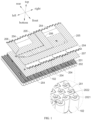
- a bus bar 202 is applied to a cylindrical power battery module 101 for connecting a plurality of rows of cells 102 arranged in width direction of the battery module 101 in parallel.
- the bus bar 202 includes a plurality of working portions 2028 arranged and connected in the width direction of the battery module 101, and the plurality of working portions 2028 is provided in one-to-one correspondence with a plurality of rows of cells 102 arranged in the width direction of the battery module 101.
- Each of the working portions 2028 includes a positive electrode portion 2021 and a negative electrode portion 2022 connected to each other.
- the positive electrode portion 2021 is connected to the positive terminal 1022 of one of the two cells 102 provided adjacent to each other in the length direction of the battery module 101
- the negative electrode portion 2022 is connected to the negative terminal 1021 of the other of the two cells 102 provided adjacent to each other in the length direction of the battery module 101.
- the positive electrode portion 2021 and/or the negative electrode portion 2022 are provided with a glue injection port 2024 which communicates to the gap between the two cells 102 connected by the working portion 2028 in series along the lengthwise direction of the battery module 101.
- the width direction of the battery module 101 refers to the left-right direction as shown in FIG. 1 ; and the length direction of the battery module 101 refers to the front-rear direction as shown in FIG. 1 .
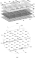
- a battery pack is provided, and the battery pack includes eight battery modules 101 as shown in FIG. 3 , which constitute two battery packs 100. Further, a row of cells 102 arranged in the length direction of the battery module 101 (that is, arranged in the front-rear direction of the battery pack as shown in FIG. 1 ) is defined as a battery row, and the battery module 101 includes five battery rows arranged in the left-right direction of the battery pack as shown in FIG. 1 . Accordingly, the bus bar 202 may include five working portions 2028 arranged in the width direction of the battery module 101, and the five working portions 2028 corresponds to five battery rows in a same battery module 101. The working portion 2028 is used to connect two adjacent cells 102 in a battery row in series.
- foam glue may be selectively injected into the gaps between two adjacent cells 102 through a glue injection port 2024.
- the foam glue can be uniformly filled in the gaps between any two adjacent cells 102 while the glue injection efficiency is improved, thereby improving the bonding and fixing quality of the battery module 101.
- an excessive amount of the foam glue can overflow upward through the glue injection port 2024.
- the upward jacking force of the foam glue to the bus bar 202 in the longitudinal direction can be greatly reduced, and the risk of welding-off the bus bar 202 and the cell 102 due to foaming of the foam glue can be reduced.
- the foam glue is injected through the glue injection port 2024 at the time that no foam glue is provided in the gap between the corresponding two cells 102 after the foam glue is injected in the conventional mode. It is also possible to directly inject the foam glue into the gap between the two cells 102 through the glue injection ports 2024, which on the one hand, the glue injection efficiency can be improved, and on the other hand, even filling of the foam glue in the gap between any two adjacent cells 102 can be ensured, thereby ensuring the bonding and fixing quality of the battery module 101.
- At least one glue injection port 2024 is provided at the junction of the positive electrode portion 2021 and the negative electrode portion 2022. Since the junction between the positive electrode portion 2021 and the negative electrode portion 2022 is closest to the gap between the two adjacent cells 102 corresponding to the working portion 2028, the glue flows rapidly to the gap between the two adjacent cells 102, thereby facilitating rapid glue injection and glue spill. In some embodiments, the glue injection port 2024 is disposed at the junction between the positive electrode portion 2021 and the negative electrode portion 2022.
- the positive electrode portion 2021 is provided with a glue spill hole 2027 which communicates to the gap between two cells 102 connected by the working portion 2028 in series along the longitudinal direction of the battery module 101.
- the glue spill hole 2027 can increase the overflow of the foam glue in addition to the glue injection port 2024 during the glue spill process, and the glue spill hole 2027 can further improve the glue spill efficiency.
- the glue spill hole 2027 can also overflow excess foam glue as the foam glue is foamed in the longitudinal direction, to prevent the foam glue from raising the bus bar 202 to some extent to cause failure of the welded structure between the bus bar 202 and the cell 102.
- the positive electrode portion 2021 is provided with a weakened hole 2025 therethrough.
- the weakened hole 2025 here functions as a protection circuit. Specifically, the weakened hole 2025 reduces the over-current area of the working portion 2028. When the battery pack system is short-circuited externally or internally, the temperature of the working portion 2028 rises due to over-current, and the working portion 2028 fuses at the weakened hole 2025. As such, the weakened hole 2025 functions as a fuse.
- the weakened hole 2025 can also serve as a glue injection port, and accordingly, the glue injection port 2024 can also serve as a weakened hole.
- the weakened hole 2025 is provided at a side of the positive electrode portion 2021 adjacent to the negative electrode portion 2022. That is, the weakened hole 2025 is provided close to the junction of the positive electrode portion 2021 and the negative electrode portion 2022, to function as a glue injection port during the glue injection process. Further, the weakened holes 2025 are at both ends of the glue injection port 2024 in the width direction of the bus bar 202. In some embodiments, the weakened holes 2025 on the same working portion 2028 are equally divided into two groups, and the two groups of weakened holes 2025 are symmetrically arranged with respect to the glue injection port 2024.
- width direction of the bus bar 202 is parallel to the width direction of the battery module 101.
- the positive electrode portion 2021 and the negative electrode portion 2022 are connected by a bending portion 2029.
- the plane in which the positive electrode portion 2021 is located is higher than the plane in which the negative electrode portion 2022 is located, and the plane in which the positive electrode portion 2021 is located is parallel to the plane in which the negative electrode portion 2022 is located.
- the negative terminal 1021 and the positive terminal 1022 of the cell 102 are each at one end of the cell 102 along the height direction, and the top surface of the positive terminal 1022 is higher than the top surface of the negative terminal 1021.
- the height difference between the bottom surface of the positive electrode portion 2021 of the bus bar 202 and the bottom surface of the negative electrode portion 2022 of the bus bar 202 in the longitudinal direction is equal to the height difference between the top surface of the positive terminal 1022 and the top surface of the negative terminal 1021 in the longitudinal direction.
- an end of the negative electrode portion 2022 away from the positive electrode portion 2021 is provided with an avoidance notch 2023, to keep away from the positive terminal 1022 of the cell 102 connected to the negative electrode portion 2022.
- the negative electrode portion 2022 can have a larger contact area with the negative terminal 1021 of the cell 102, thereby improving the welding strength of both.
- connection portion 2026 is connected to the positive electrode portion 2021.
- the positive electrode portion 2021, the negative electrode portion 2022, the bending portion 2029, and the connecting portion 2026 are integrally stamped.
- a bus bar assembly is provided, and the bus bar assembly includes a plurality of the bus bars 202 as above, a series bar 204, a positive electrode bar 205, and a negative electrode bar 206.
- the plurality of bus bars 202 are arranged in the length direction of the battery module 101 and constitute a connection bar assembly.
- the connection bar assembly is configured to connect two cells 102 arranged adjacent to each other in the length direction in series, and to connect two cells 102 arranged adjacent to each other in the width direction in parallel.
- the series bar 204 is disposed on the upper side of the connection bar assembly to connect two adjacent battery modules 101 in series to constitute a battery pack 100.
- the positive bar 205 is connected to the positive output terminal of the battery pack 100, and the positive bar 205 is disposed on the top of the battery pack 100.
- the negative electrode bar 206 is connected to the negative output terminal of the battery pack 100, and the negative electrode bar 206 is disposed on the top of the battery pack 100.
- the bus bar assembly provided is applied to a battery pack including eight battery modules 101, corresponding to eight connection bar assemblies, as shown in FIG. 3 .
- the eight battery modules 101 constitute two battery packs 100.
- the bus bar assembly further includes a first insulating layer 201.
- the first insulating layer 201 is attached to the upper side and the lower side of the connection bar assembly to fix all connection bar assemblies corresponding to the same battery module 101, or to fix all battery modules 101 corresponding to all connection bar assemblies. At least a portion of the positive electrode portion 2021, at least a portion of the negative electrode portion 2022, and at least a portion of the glue injection port 2024 are exposed from the first insulating layer 201.
- an operation hole 203 is provided through the first insulating layer 201, and with two adjacent working portions 2028 along the length direction of the battery module 101, the positive electrode portion 2021 of one of the two adjacent working portions 2028 is exposed from the first insulating layer 201 through the operation hole 203, and the negative electrode portion 2022 of the other one of the two adjacent working portions 2028 is also exposed from the first insulating layer 201 through the operation hole 203.
- the first insulating layer 201 includes, but is not limited to, a PET insulating film.
- the first insulating layer 201 herein is capable of positioning and securing all the bus bars 202 corresponding to the same connection bar assembly as a whole, meanwhile performing insulation on the upper side and the lower side of the connection bar assembly.
- the portion of the bus bar 202 exposed from the operation hole 203 is used for welding with nickel sheet of the positive terminal 1022 and the negative terminal 1021 of the cell 102 or the FPC or the collecting wire harness.
- one battery pack 100 provided on the left side is taken as an example for easy description.
- Battery modules 101 provided from left to right in the battery pack 100 are sequentially defined as a first module, a second module, a third module, and a fourth module.
- the rear end of the first module is the negative output terminal of the battery pack 100
- the rear end of the fourth module is the positive output terminal of the battery pack 100.
- the front end of the first module and the front end of the second module are connected in series
- the rear end of the second module and the rear end of the third module are connected in series
- the front end of the third module and the front end of the fourth module are connected in series.
- the negative electrode bar 206 electrically connected to the negative output terminal of the first module and the positive electrode bar 205 electrically connected to the positive output terminal of the fourth module are high-voltage outputs of the battery pack 100.
- the positive electrode bar 205, the negative electrode bar 206 and the series bar 204 are all located on the upper side of the bus bar 202.
- the positive electrode bar 205 and the negative electrode bar 206 are routed at the top of the battery pack 100.
- the positive output terminal and the negative output terminal of the battery pack 100 can be directly output to a high-voltage connector (not shown) of the battery pack.
- wiring and layout of the positive electrode bar 205 and the negative electrode bar 206 are facilitated due to the large space at the top of the battery pack 100.
- the space on the circumference of the battery pack 100 can be saved, to improve energy density of the battery pack.
- the problem that the battery pack is short-circuited due to the high-voltage copper bar is squeezed can be solved.
- the battery pack provided in some embodiments has a greater buffer space (this is, a space between the battery pack 100 and the inner wall of the case) for squeezing and a higher safety, on the premise that the battery pack has the same space.
- the bus bar 202 can provide an upward supporting force to the positive electrode bar 205 and the negative electrode bar 206 in the longitudinal direction (this is, the upper-lower direction as shown in FIG. 1 ), and the positive electrode bar 205, the negative electrode bar 206, the series bar 204.
- the bus bar 202 are integrally solidified and molded by means of glue filling in use, which is beneficial for ensuring the structural stability of the connection structure of the positive electrode bar 205 and the negative electrode bar 206 with the battery pack 100, respectively, and further improving the safety of the battery pack.
- the bus bar assembly further includes a second insulating layer 207 between the series bar 204 and the respective connection bar assembly, the positive electrode bar 205 and the respective connection bar assembly, and the negative electrode bar 206 and the respective connection bar assembly.
- the series bar 204, the positive electrode bar 205, and the negative electrode bar 206 on the upper side of the connection bar assembly are defined as upper high-voltage bars, and a plurality of connection bar assemblies are defined as lower low-voltage bars.
- the second insulating layer 207 serves to realize insulation between the upper high-voltage bars and the lower low-voltage bars to avoid a short circuit.
- the second insulating layer 207 includes, but is not limited to, a PET insulating film or a plastic sheet.
- the second insulating layer 207 is a plastic insulating plate, and the series bar 204, the positive electrode bar 205 and the negative electrode bar 206 are all disposed on the upper surface of the insulating plate.
- the structure of the second insulating layer 207 has a relatively higher strength to support the upper high-voltage bars, thereby facilitating the positioning and mounting of the upper high-voltage bars (that is, the series bar 204, the positive electrode bar 205, and the negative electrode bar 206).
- the plastic insulating plate can act as a pressing plate to limit foaming of the foam glue in the longitudinal direction, thereby facilitating uniform foaming and diffusing of the foam glue in the space under the plastic insulating plate, and improving the bonding quality of the components.
- the thickness of the second insulating layer 207 is not greater than 2 mm. In some embodiments, the thickness of the second insulating layer 207 is 1.5 mm. With this arrangement, on the one hand, it is possible to maintain sufficient strength of the second insulating layer 207, and on the other hand, it is possible to effectively control the thickness of the second insulating layer 207, thereby reducing the occupancy at the top of the case.
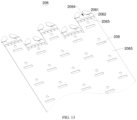
- a plurality of insulating glue injection ports 208 are provided through the second insulating layer 207, and the insulating glue injection port 208 communicates with the gaps between two adjacent cells 102 correspondingly arranged in the length direction.
- the foam glue can be injection into the gap between the two adjacent cells 102 through the insulating glue injection port 208 easily and efficiently, thereby ensuring the bonding quality between the cells 102.
- a third insulating layer is coated on the outer sides of the series bar 204, the positive electrode bar 205 and the negative electrode bar 206. A connecting end of the series bar 204, the positive electrode bar 205 and the negative electrode bar 206 are exposed from the third insulating layer, respectively.
- the third insulating layer includes, but is not limited to, a PET insulating film.
- the insulation between the upper high-voltage bar and the lower low-voltage bar is effectively ensured, and a short circuit between the upper high-voltage bar and the lower low-voltage bar can be effectively prevented.
- the thickness of the positive electrode bar 205 and the thickness of the negative electrode bar 206 are not greater than 1 mm. In some embodiments, the thickness of the positive electrode bar 205, the negative electrode bar 206 and the series bar 204 are all 1 mm. Further, the positive electrode bar 205 and the negative electrode bar 206 are plate bars. In some embodiments, the positive electrode bar 205 and the negative electrode bar 206 are aluminum plate bars or copper plate bars. In some embodiments, the positive electrode bar 205, the negative electrode bar 206 and the series bar 204 are each made of thin aluminum plates.
- the upper high-voltage bars take less space in the case along the height direction, and the thin aluminum plate has a relatively better effect on heat dissipation, the safety is high, which provides a high safety, a convenient production, and a low cost.
- the positive electrode bar 205 includes a first body 2054, an input terminal of the first body 2054 is provided with a first extension portion 2052, an end of the first extension portion 2052 is provided with a first positive electrode portion 2051, and the first positive electrode portion 2051 is connected to the positive terminal of the cell 102 at the positive output terminal of the battery pack 100.
- the input terminal of the first body 2054 is provided with five first extension portions 2052 corresponding to five battery rows of the same battery module 101.
- the first positive electrode portion 2051 is welded to the positive terminal of the cell 102 corresponding thereto.
- a positive weakened hole 2053 is provided through the first extension portion 2052.
- the positive weakened hole 2053 can reduce the over-current area of the first extension portion 2052.
- the structure at the positive weakened hole 2053 is fused to function as a fuse.
- the negative electrode bar 206 includes a second body 2065, an input end of the second body 2065 is provided with a second extension portion 2062, an end of the second extension portion 2062 is provided with a first negative electrode portion 2061, and the first negative electrode portion 2061 is connected to the negative terminal of the cell 102 at the negative output terminal of the negative electrode of the battery pack 100.
- the input terminal of the second body 2065 is provided with five second extension portions 2062 corresponding to five battery rows of the same battery module 101.
- the first negative electrode portion 2061 is welded to the negative terminal of the cell 102 corresponding thereto.
- a negative weakened hole 2063 is provided through the second extension portion 2062. The negative weakened hole 2063 can reduce the over-current area of the second extension portion 2062. In a case that the battery pack is short-circuited externally or internally, the structure at the negative weakened hole 2063 is fused to function as a fuse.
- the second extension portion 2062 is provided with a negative electrode avoidance notch 2064, and the negative electrode avoidance notch 2064 extends through the first negative electrode portion 2061.
- the negative electrode avoidance notch 2064 here serves to avoid the positive terminal of the cell 102 connected to the first negative electrode portion 2061.
- the positive electrode bar 205 and the negative electrode bar 206 each are provided with a plate glue injection port 209 corresponding to the insulating glue injection port 208. Note that, in the longitudinal direction, the insulating glue injection port 208 and the corresponding plate glue injection port 209 are opposite and communicated. That is, the plate glue injection port 209 is exposed from the third insulating layer.
- the plate glue injection port 209 is also provided on the series bar 204. In some embodiments, the plate glue injection port 209 and the corresponding insulating glue injection port 208 on the series bar 204 are aligned and communicated.
- the glue injection port 2024 and the corresponding insulating glue injection port 208 are aligned and communicated. Specifically, after the bus bar assembly of the battery pack is installed, the foam glue is injected from the plate glue injection port 209 and the insulating glue injection port 208, and the foam glue passes through the operation hole 203 and the glue injection port 2024 into the gap between two adjacent cells 102.
- the positive electrode bar 205 and the negative electrode bar 206 are each provided with a first hole structure which is longitudinally opposite to the glue injection port 2024 and the glue spill hole 2027. As such, the foam glue can be directly injected into the glue injection port 2024 through the first hole structure, after the bus bar assembly is installed. In a case that the foam glue is foamed upward in the longitudinal direction, the foam glue overflowing through the glue spill hole 2027 and the glue injection port 2024 can flow to the upper side of the bus bar 202 through the corresponding first hole structure.
- the second insulating layer 207 is also provided with a second hole structure which is longitudinally opposite to the glue injection port 2024 and the glue spill hole 2027, and functions as the first hole structure.
- the details of the second hole structure are not described herein.
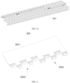
- the series bar includes a third body 2041, and a positive electrode module 2042 and a negative electrode module 2043 are provided on the same side of the third body 2041.
- the positive electrode module 2042 is used to be connected to the positive terminal of the corresponding one battery module 101.
- the negative electrode module 2043 is used to be connected to the negative terminal of the other battery module 101 adjacent to the corresponding one battery module 101.
- the corresponding one battery module 101 and the other battery module 101 adjacent to the corresponding one battery module 101 are connected in series.
- the structure of the positive electrode module 2042 corresponds to the structure of the input terminal of the first body 2054 of the positive electrode bar 205.
- the structure of the negative electrode module 2043 corresponds to the structure of the input terminal of the second body 2065 of the negative electrode bar 206. Details are not described herein.
Landscapes
- Chemical & Material Sciences (AREA)
- Chemical Kinetics & Catalysis (AREA)
- Electrochemistry (AREA)
- General Chemical & Material Sciences (AREA)
- Inorganic Chemistry (AREA)
- Connection Of Batteries Or Terminals (AREA)
Applications Claiming Priority (3)
| Application Number | Priority Date | Filing Date | Title |
|---|---|---|---|
| CN202321375618.7U CN220122045U (zh) | 2023-05-31 | 2023-05-31 | 一种汇流排、汇流排组件及电池包 |
| CN202310640809.XA CN116706444B (zh) | 2023-05-31 | 2023-05-31 | 一种汇流排组件及电池包 |
| CN202321375352.6U CN220122044U (zh) | 2023-05-31 | 2023-05-31 | 一种汇流排组件及电池包 |
Publications (1)
| Publication Number | Publication Date |
|---|---|
| EP4471968A1 true EP4471968A1 (de) | 2024-12-04 |
Family
ID=89073093
Family Applications (1)
| Application Number | Title | Priority Date | Filing Date |
|---|---|---|---|
| EP23213579.8A Pending EP4471968A1 (de) | 2023-05-31 | 2023-12-01 | Stromschiene, stromschienenanordnung und batteriepack |
Country Status (3)
| Country | Link |
|---|---|
| US (1) | US20240128595A1 (de) |
| EP (1) | EP4471968A1 (de) |
| WO (1) | WO2024244074A1 (de) |
Citations (4)
| Publication number | Priority date | Publication date | Assignee | Title |
|---|---|---|---|---|
| CN113764832A (zh) * | 2021-09-30 | 2021-12-07 | 蜂巢能源科技有限公司 | 汇流排组件及具有其的电池模组 |
| CN115172996A (zh) * | 2022-07-08 | 2022-10-11 | 湖北亿纬动力有限公司 | 一种具有ccs组件的电池包 |
| CN217788692U (zh) * | 2022-06-17 | 2022-11-11 | 湖北亿纬动力有限公司 | 一种电池包 |
| EP4138191A1 (de) * | 2020-12-29 | 2023-02-22 | Svolt Energy Technology Company Limited | Batteriemodul, strombatterie und fahrzeug |
Family Cites Families (11)
| Publication number | Priority date | Publication date | Assignee | Title |
|---|---|---|---|---|
| JP3245022B2 (ja) * | 1995-09-14 | 2002-01-07 | 松下電器産業株式会社 | 鉛蓄電池及びその製造方法 |
| US20150326177A1 (en) * | 2014-05-06 | 2015-11-12 | Integrated Solar Technology, LLC | Integrated Wire Management for Roof-Integrated Solar Panels |
| JP6315007B2 (ja) * | 2016-02-23 | 2018-04-25 | トヨタ自動車株式会社 | 電池モジュール |
| CN108448041B (zh) * | 2018-05-02 | 2024-08-20 | 中创新航技术研究院(江苏)有限公司 | 一种软包锂离子电池模块及连接方法 |
| CN211670268U (zh) * | 2020-04-23 | 2020-10-13 | 洛阳超特电源科技有限公司 | 一种电池模组 |
| CN214625320U (zh) * | 2020-12-31 | 2021-11-05 | 重庆金康动力新能源有限公司 | 电池包的注胶孔及电池包 |
| KR20220128310A (ko) * | 2021-03-12 | 2022-09-20 | 주식회사 엘지에너지솔루션 | 버스바 어셈블리, 이러한 버스바 어셈블리를 포함하는 배터리 팩 및 이러한 배터리 팩을 포함하는 자동차 |
| US20230080258A1 (en) * | 2021-09-10 | 2023-03-16 | Kitty Hawk Corporation | Battery system with cylindrical battery cells and ribbon bonding |
| CN214848948U (zh) * | 2021-10-27 | 2021-11-23 | 嘉兴模度新能源有限公司 | 一种具有低功率顶部汇流排的电池组及电池包 |
| KR102743778B1 (ko) * | 2021-11-02 | 2024-12-18 | 주식회사 블루시그마 | 망 형태의 버스 바 연결 구조를 갖는 배터리 팩 |
| CN114566764A (zh) * | 2022-01-25 | 2022-05-31 | 湖北亿纬动力有限公司 | 一种汇流排组件及大圆柱动力电池模组 |
-
2023
- 2023-06-26 WO PCT/CN2023/102279 patent/WO2024244074A1/zh not_active Ceased
- 2023-11-27 US US18/519,262 patent/US20240128595A1/en active Pending
- 2023-12-01 EP EP23213579.8A patent/EP4471968A1/de active Pending
Patent Citations (4)
| Publication number | Priority date | Publication date | Assignee | Title |
|---|---|---|---|---|
| EP4138191A1 (de) * | 2020-12-29 | 2023-02-22 | Svolt Energy Technology Company Limited | Batteriemodul, strombatterie und fahrzeug |
| CN113764832A (zh) * | 2021-09-30 | 2021-12-07 | 蜂巢能源科技有限公司 | 汇流排组件及具有其的电池模组 |
| CN217788692U (zh) * | 2022-06-17 | 2022-11-11 | 湖北亿纬动力有限公司 | 一种电池包 |
| CN115172996A (zh) * | 2022-07-08 | 2022-10-11 | 湖北亿纬动力有限公司 | 一种具有ccs组件的电池包 |
Also Published As
| Publication number | Publication date |
|---|---|
| WO2024244074A1 (zh) | 2024-12-05 |
| US20240128595A1 (en) | 2024-04-18 |
Similar Documents
| Publication | Publication Date | Title |
|---|---|---|
| TWI751427B (zh) | 電池連接模組 | |
| JP7048838B2 (ja) | バスバーを備えたバッテリーモジュール及びバッテリーパック | |
| JP7062177B2 (ja) | モジュールバスバーを含むバッテリーモジュール | |
| KR102177694B1 (ko) | 버스바 어셈블리를 포함하는 배터리 모듈 | |
| KR102532699B1 (ko) | 전지 모듈 및 이를 포함하는 전지팩 | |
| KR20200080074A (ko) | Fpcb에 실장된 커넥터를 구비하는 배터리 모듈, 이를 포함하는 배터리 팩 및 자동차 | |
| KR20210000260A (ko) | 커버 구조물을 포함하는 배터리 팩 및 전자 디바이스 및 자동차 | |
| KR20220130425A (ko) | 하이브리드 회로 기판 및 이를 갖는 배터리 팩 | |
| KR20220085396A (ko) | 배터리 팩 및 이 배터리 팩의 제조 방법 | |
| KR20230117378A (ko) | 버스바 어셈블리 및 원통형 파워 배터리 모듈 | |
| CN212542554U (zh) | 电池模组、用于电池模组成组的工装及电动汽车 | |
| CN113036313A (zh) | 一种电池模组 | |
| CN214505696U (zh) | 一种用于车辆的电池模组 | |
| CN116706444A (zh) | 一种汇流排组件及电池包 | |
| CN213366723U (zh) | 电芯组件、电池模组及电池系统 | |
| CN219163629U (zh) | 电池包及动力装置 | |
| CN114725624B (zh) | 电池模组及工程车辆 | |
| CN217589272U (zh) | 电芯模块和电池包 | |
| US20240128595A1 (en) | Bus bar, bus bar assembly and battery pack | |
| CN209592169U (zh) | 一种动力电池软包模组 | |
| CN220122045U (zh) | 一种汇流排、汇流排组件及电池包 | |
| CN212303844U (zh) | 电池模组和电池包 | |
| JP7764594B2 (ja) | バッテリーパックおよびバッテリーパックの製造方法 | |
| KR102754904B1 (ko) | 전지 모듈 및 이를 포함하는 전지팩 | |
| CN218525681U (zh) | 一种支持多层结构的电池模组 |
Legal Events
| Date | Code | Title | Description |
|---|---|---|---|
| PUAI | Public reference made under article 153(3) epc to a published international application that has entered the european phase |
Free format text: ORIGINAL CODE: 0009012 |
|
| STAA | Information on the status of an ep patent application or granted ep patent |
Free format text: STATUS: REQUEST FOR EXAMINATION WAS MADE |
|
| 17P | Request for examination filed |
Effective date: 20231201 |
|
| AK | Designated contracting states |
Kind code of ref document: A1 Designated state(s): AL AT BE BG CH CY CZ DE DK EE ES FI FR GB GR HR HU IE IS IT LI LT LU LV MC ME MK MT NL NO PL PT RO RS SE SI SK SM TR |