EP4471386A1 - Weight inspection device - Google Patents
Weight inspection device Download PDFInfo
- Publication number
- EP4471386A1 EP4471386A1 EP23743321.4A EP23743321A EP4471386A1 EP 4471386 A1 EP4471386 A1 EP 4471386A1 EP 23743321 A EP23743321 A EP 23743321A EP 4471386 A1 EP4471386 A1 EP 4471386A1
- Authority
- EP
- European Patent Office
- Prior art keywords
- conveyance
- beam portions
- weighing unit
- beam portion
- frame
- Prior art date
- Legal status (The legal status is an assumption and is not a legal conclusion. Google has not performed a legal analysis and makes no representation as to the accuracy of the status listed.)
- Pending
Links
Images



Classifications
-
- G—PHYSICS
- G01—MEASURING; TESTING
- G01G—WEIGHING
- G01G11/00—Apparatus for weighing a continuous stream of material during flow; Conveyor belt weighers
-
- G—PHYSICS
- G01—MEASURING; TESTING
- G01G—WEIGHING
- G01G11/00—Apparatus for weighing a continuous stream of material during flow; Conveyor belt weighers
- G01G11/003—Details; specially adapted accessories
-
- G—PHYSICS
- G01—MEASURING; TESTING
- G01G—WEIGHING
- G01G21/00—Details of weighing apparatus
- G01G21/23—Support or suspension of weighing platforms
-
- G—PHYSICS
- G01—MEASURING; TESTING
- G01G—WEIGHING
- G01G21/00—Details of weighing apparatus
- G01G21/28—Frames, Housings
Definitions
- the present disclosure relates to a weight inspection apparatus.
- the weight inspection apparatus includes a take-in unit that takes in an object to be inspected, and a weighing unit that detects a weight of the object supplied from the take-in unit.
- the take-in unit and the weighing unit are supported by a frame.
- the frame includes a pair of inverted U-shaped leg members disposed at a predetermined distance in a conveyance direction (X-axis direction in Patent Literature 1) and a pair of rail-shaped members fixed on the pair of leg members and extending in the conveyance direction.
- the rail-shaped member is fixed to a horizontal portion of the leg member by welding or the like.
- the rail-shaped member supports a weighing box of the weighing unit and a take-in box of the take-in unit.
- a load cell which is a strain generation body is attached in the weighing box.
- a fixed end on one side of the load cell is fixed in the weighing box, and a free end on the other side of the load cell supports a weighing conveyor via a motor box housing a drive motor and a pair of support members.
- the weight of the weighing conveyor itself and the weight of the object are transmitted to the free end of the load cell via the support member, the motor box, and the like.
- Patent Literature 1 Japanese Patent No. 5064973
- the frame structure of the conventional weight inspection apparatus has a problem of low rigidity. To perform stable measurement while securing rigidity, the weight of the apparatus increases, and thus it has been difficult to reduce the weight of the apparatus.
- the present disclosure describes a weight inspection apparatus that enables weight reduction while increasing rigidity of a frame.
- a weight inspection apparatus includes a conveyance weighing unit that measures a weight of an object to be inspected while conveying the object in a conveyance direction, and a frame that supports the conveyance weighing unit, wherein the frame includes at least four support columns disposed at positions not overlapping with the conveyance weighing unit in plan view, and at least four beam portions forming a quadrangle in plan view, each of the at least four beam portions being connected to any two of the support columns, and the beam portions include a pair of first beam portions, each of the pair of first beam portions being connected to two support columns arranged in the conveyance direction, and a height of an upper end of at least one of the first beam portions is equal to a height of a conveyance surface of the conveyance weighing unit or higher than the height of the conveyance surface.
- this weight inspection apparatus at least four beam portions are disposed to form a quadrangle in plan view, and each beam portion is connected to the support column.
- the rigidity of the frame is increased. Vibration may adversely affect the measurement of an object to be inspected. Since the rigidity of the frame is increased, the weight inspection apparatus is less likely to be affected by vibration. In addition, it is also easy to reduce the weight of all or a part of the four beam portions while securing rigidity. This makes it possible to reduce the weight of the frame.
- the beam portions may include a pair of second beam portions connected to two support columns arranged in a width direction orthogonal to the conveyance direction, and the height of the second beam portions may be lower than the heights of the two support columns. In this case, the center of gravity of the frame is lowered, and thus stability is enhanced.
- the conveyance weighing unit may be supported by the second beam portions. Since the conveyance weighing unit is supported at a lower position of the frame, the center of gravity of the entire weight inspection apparatus is lowered, and the stability is enhanced.
- the second beam portions may be shorter than the first beam portions. Since the conveyance weighing unit is supported by the relatively short second beam portions, the frame can stably support the conveyance weighing unit. Resistance to vibration also improves.
- the beam portions may include a pair of long-side beam portions forming long sides of the quadrangle and a pair of short-side beam portions forming short sides of the quadrangle, and the conveyance weighing unit may be supported by the short-side beam portions. Since the conveyance weighing unit is supported by the short-side beam portions, the frame can stably support the conveyance weighing unit. Resistance to vibration also improves.
- the frame may include at least two second beam portions included in the beam portions, each of the at least two second beam portions being connected to two support columns arranged in a width direction orthogonal to the conveyance direction among the support columns, and a base member that is bridged between the at least two second beam portions and supports the conveyance weighing unit, wherein a base width that is a size in the width direction of the base member is equal to a lower end width that is a size in the width direction of a lower end of the conveyance weighing unit or larger than the lower end width.
- the second beam portions may be the short-side beam portions.
- the width direction may be a direction of the short side.
- the base portion having a base width equal to the lower end width or larger than the lower end width of the conveyance weighing unit is bridged over the second beam portions (or the short-side beam portions). Since the base portion supports the conveyance weighing unit, torsion is less likely to occur than in a conventional structure in which two conventional rail-shaped members are used. In addition, according to the base portion having a large base width, rigidity is also secured. As a result of realizing the prevention of torsion and the increase in rigidity, the weighing accuracy also improves.
- the rigidity of the frame is increased, and further, the weight of the frame can be reduced.
- the weight inspection apparatus 100 is an apparatus that checks whether the weight of the object P is within an allowable range while conveying the object P supplied from the upstream side to the downstream side. As illustrated in FIG. 1 , the weight inspection apparatus 100 mainly includes 1, a main body 40, and a frame 50.
- a conveyance weighing unit 20 is attached to the frame 50 and includes an intake portion 10 disposed on the upstream side (left side in the drawing) and a weighing device 30 disposed on the downstream side (right side in the drawing).
- the intake portion 10 of the conveyance weighing unit 20 receives and conveys the object P from the upstream side, and delivers the object P to the weighing device 30 on the downstream side.
- the intake portion 10 includes an intake conveyor (intake conveyor unit) 11 and a drive unit 15.
- the intake conveyor 11 includes a conveyor frame 12, a driving roller 13A, a driven roller 13B, and a conveying belt 14.
- the conveyor frame 12 is supported by a pair of support members 61 disposed on the front side and the back side of the intake conveyor 11.
- the driving roller 13A and the driven roller 13B are rotatably attached to the upstream side and the downstream side of the conveyor frame 12 in the conveyance direction TD, respectively.
- the conveying belt 14 is an endless belt wound around the driving roller 13A and the driven roller 13B.
- the drive unit 15 drives the intake conveyor 11.
- the drive unit 15 includes a drive motor 16 and a motor box 17.
- the drive motor 16 rotates the driving roller 13A.
- the motor box 17 houses the drive motor 16.
- the motor box 17 is fixed to a base member 58 (to be described in detail later) of the frame 50 via the support member 61.
- the motor box 17 may be directly fixed to the base member 58 of the frame 50.
- the drive motor 16 transmits driving force to the driving roller 13A via a timing belt 18 to rotate the driving roller 13A. This causes the conveying belt 14 to rotate between the driving roller 13A and the driven roller 13B, and the object P on the conveying belt 14 is conveyed to the conveyance weighing unit 20.
- the weighing device 30 of the conveyance weighing unit 20 weighs the weight of the object P while conveying the object P delivered from the intake portion 10.
- the weighing device 30 includes a conveyance unit 20A and a weighing unit 20B.
- the conveyance unit 20A conveys the object P.
- the conveyance unit 20A includes a carrying conveyor 21 and a drive unit 25.
- the conveyance direction TD of the carrying conveyor 21 is a horizontal direction in the present embodiment, and is the same as the conveyance direction TD of the intake conveyor 11.
- the carrying conveyor 21 includes a conveyor frame 22, a driving roller 23A and a driven roller 23B, and a conveying belt 24.
- the conveyor frame 22 is supported by a pair of support members 62 disposed on the front side and the back side of the conveyance weighing unit 20.
- the driving roller 23A and the driven roller 23B are rotatably attached to the upstream side and the downstream side of the conveyor frame 22 in the conveyance direction TD, respectively.
- the conveying belt 24 is an endless belt wound around the driving roller 23A and the driven roller 23B.
- the drive unit 25 drives the carrying conveyor 21.
- the drive unit 25 includes a drive motor 26 and a motor box 27.
- the drive motor 26 rotates the driving roller 23A.
- the motor box 27 houses the drive motor 26.
- the motor box 27 is fixed to the base member 58 of the frame 50 via the support member 62.
- the motor box 27 may be directly fixed to the base member 58 of the frame 50.
- the drive motor 26 transmits driving force to the driving roller 23A via a timing belt 28 to rotate the driving roller 23A. This causes the conveying belt 24 to rotate between the driving roller 23A and the driven roller 23B, and the object P on the conveying belt 24 is conveyed to the downstream side.
- the weighing unit 20B measures the weight of the object P on the conveyance unit 20A.
- the weighing unit 20B includes a load cell 31 and a weighing box 32.
- the load cell 31 detects a change in distortion caused by the object P being placed on the conveyance unit 20A, and it measures the weight of the object P placed on the conveyance unit 20A.
- the weighing box 32 is fixed to the base member 58 of the frame 50.
- the weighing box 32 houses the load cell 31.
- the main body 40 is disposed behind the weighing device 30.
- the main body 40 includes a housing unit 41, a control unit 42, a display operation unit 43, and a power switch 44.
- the main body 40 is fixed to a lower beam portions 55 of the frame 50.
- the housing unit 41 is a vertically long housing extending in the up-down direction.
- the control unit 42 is housed in the housing unit 41.
- the control unit 42 controls operation of each unit of the weight inspection apparatus 100.
- the control unit 42 includes, for example, a CPU, a ROM, a RAM, and the like.
- the control unit 42 receives a weighing signal output from the load cell 31 and determines whether the weighing value indicated by the weighing signal is within a predetermined allowable range.
- the display operation unit 43 is provided in an upper portion of the housing unit 41.
- a screen 43a of the display operation unit 43 displays contents related to measurement performed by the weighing device 30. For example, a result of determination by the control unit 42 and the like are displayed on the screen 43a of the display operation unit 43.
- the power switch 44 turns on and off the power of the weight inspection apparatus 100.
- the frame 50 supports the conveyance weighing unit 20. That is, the frame 50 supports both the intake portion 10 and the weighing device 30.
- the frame 50 includes four support columns 51 and 52 standing on an installation surface (ground) F of the weight inspection apparatus 100.
- the four support columns 51 and 52 extend straight in the up-down direction, for example, and are parallel to each other.
- the frame 50 includes a pair of left support columns 51 disposed on the upstream side and a pair of right support columns 52 disposed on the downstream side.
- the pair of left support columns 51 is disposed so as to be separated from each other at a predetermined interval in a width direction (front-back direction) orthogonal to the conveyance direction TD.
- the pair of right support columns 52 is disposed so as to be separated from each other at a predetermined interval in the width direction (front-back direction) orthogonal to the conveyance direction TD.
- the four support columns 51 and 52 are disposed at positions of vertexes of a quadrangle in plan view.
- the interval between the pair of left support columns 51 and the interval between the pair of right support columns 52 are, for example, equal, and the conveyance weighing unit 20 is housed within the range of the interval in the front-back direction. As illustrated in FIG.
- the four support columns 51 and 52 are disposed at positions not overlapping with the conveyance weighing unit 20 in plan view.
- the four support columns 51 and 52 are disposed around the conveyance weighing unit 20 (around in the horizontal direction).
- Each of the support columns 51 and 52 is formed of, for example, a circular tubular member made of metal.
- one of the pair of left support columns 51 disposed on the front side may be referred to as a left support column 51A, and one disposed on the back side may be referred to as a left support column 51B.
- One of the pair of right support columns 52 disposed on the front side may be referred to as a right support column 52A, and one disposed on the back side may be referred to as a right support column 52B.
- the left support column 51A, the left support column 51B, the right support column 52A, and the right support column 52B are parallel to each other, and extend, for example, in the up-down direction.
- the height (that is, the length) of each of the left support column 51A, the left support column 51B, the right support column 52A, and the right support column 52B is equal with respect to the installation surface F.
- the frame 50 includes a pair of upper beam portions (first beam portions) 53 and a pair of lower beam portions 55 connected to the left support column 51 and the right support column 52 arranged in the conveyance direction TD.
- the upper beam portion 53 is connected to, for example, an upper end portion 51a of the left support column 51 and an upper end portion 52a of the right support column 52.
- the lower beam portion 55 is connected to, for example, a lower portion 51b of the left support column 51 and a lower portion 52b of the right support column 52.
- Each of the upper beam portions 53 and the lower beam portion 55 is formed of, for example, a square tubular member made of metal.
- Both or one of the upper beam portions 53 and the lower beam portion 55 may be a member having a C-shaped section opened downward.
- On the lower surface of the upper beam portion 53 for example, an opening 53e extending in a longitudinal direction and a pair of lower surface pieces 53f forming the opening 53e are formed (see FIG. 8(b) ).
- one of the pair of upper beam portions 53 disposed on the front side may be referred to as an upper beam portion 53A, and one disposed on the back side may be referred to as an upper beam portion 53B.
- One of the pair of lower beam portions 55 disposed on the front side may be referred to as a lower beam portion 55A, and one disposed on the back side may be referred to as a lower beam portion 55B.
- One upper beam portion 53A and one lower beam portion 55A are fixed to the left support column 51A and the right support column 52A arranged in the conveyance direction TD.
- One upper beam portion 53B and one lower beam portion 55B are fixed to the left support column 51B and the right support column 52B arranged in the conveyance direction TD.
- the housing unit 41 of the main body 40 described above is attached to the lower beam portion 55B via a bracket 47.
- the upper beam portion 53A, the upper beam portion 53B, the lower beam portion 55A, and the lower beam portion 55B are parallel to each other and extend, for example, in the horizontal direction. Lengths of the upper beam portion 53A, the upper beam portion 53B, the lower beam portion 55A, and the lower beam portion 55B are equal to each other.
- the frame 50 includes one left horizontal beam portion (second beam portion) 56 connected to the pair of left support columns 51 arranged in the width direction (front-back direction) and one right horizontal beam portion (second beam portion) 57 connected to the pair of right support columns 52 arranged in the width direction (front-back direction).
- the left horizontal beam portion 56 and the right horizontal beam portion 57 are fixed to the center portions of the left support column 51 and the right support column 52 in the up-down direction.
- Both the left horizontal beam portion 56 and the right horizontal beam portion 57 extend horizontally and are located at a height between the upper beam portion 53 and the lower beam portion 55.
- the height of the left horizontal beam portion 56 is lower than the height of the left support column 51A and lower than the height of the left support column 51B.
- the height of the right horizontal beam portion 57 is lower than the height of the right support column 52A and lower than the height of the right support column 52B.
- Each of the left horizontal beam portion 56 and the right horizontal beam portion 57 is formed of, for example, a circular tubular member made of metal.
- the left horizontal beam portion 56 and the right horizontal beam portion 57 are parallel to each other and extend, for example, in the horizontal direction.
- the length of the left horizontal beam portion 56 is equal to the length of the right horizontal beam portion 57.
- the height of the left horizontal beam portion 56 is equal to the height of the right horizontal beam portion 57.
- the frame 50 further includes the base member 58 bridged between the left horizontal beam portion 56 and the right horizontal beam portion 57.
- the base member 58 extends horizontally, for example.
- the base member 58 extends, for example, parallel to the installation surface F.
- the base member 58 is formed of, for example, a metal member having a C-shaped section opened downward.
- the base member 58 includes a flat top surface plate portion 81.
- the motor box 17 of the drive unit 15, the motor box 27 of the drive unit 25, and the weighing box 32 are fixed on the top surface plate portion 81 of the base member 58 using appropriate fastening members (bolt, nut, screw, or the like).
- the top surface plate portion 81 is an attachment surface or an installation surface for attaching the conveyance weighing unit 20 to the frame 50.
- a rectangular opening 81e having an area of about 1/2 to 1/4 of the top surface plate portion 81 is formed in a central region of the top surface plate portion 81 (see also FIG. 10 ).
- the upper beam portions 53, the lower beam portions 55, the left horizontal beam portion 56, and the right horizontal beam portion 57 are connected to the support columns 51 and 52 by welding, for example.
- the base member 58 is connected to the left horizontal beam portion 56 and the right horizontal beam portion 57 by welding, for example.
- These connection forms are not limited to welding, and may be, for example, bonding or the like, or a fixing metal fitting or the like and a fastening member may be applied.
- the two upper beam portions 53 (the upper beam portion 53A and the upper beam portion 53B), the left horizontal beam portion 56, and the right horizontal beam portion 57 form a quadrangle in plan view.
- the conveyance weighing unit 20 is disposed in the quadrangle (within a range) formed by the two upper beam portions 53, the left horizontal beam portion 56, and the right horizontal beam portion 57.
- the motor box 17, the motor box 27, and the weighing box 32 are disposed in the quadrangle (within a range) formed by the two upper beam portions 53, the left horizontal beam portion 56, and the right horizontal beam portion 57.
- both the left horizontal beam portion 56 and the right horizontal beam portion 57 are shorter than the upper beam portion 53. That is, the quadrangle formed by a frame-shaped beam portion including the four (four sides) of the pair of upper beam portions 53, the left horizontal beam portion 56, and the right horizontal beam portion 57 is a rectangle.
- the pair of upper beam portions 53 is a pair of long-side beam portions forming long sides of the rectangle.
- the left horizontal beam portion 56 and the right horizontal beam portion 57 are a pair of short-side beam parts forming short sides of the rectangle.
- the width direction is a direction in which the short-side beam portion extends, and corresponds to a "short-side direction" described in the claims.
- the conveyance weighing unit 20 is supported by the base member 58. That is, the intake portion 10 and the weighing device 30 are supported by the base member 58. In other words, the conveyance weighing unit 20 is supported by the left horizontal beam portion 56 and the right horizontal beam portion 57 via the base member 58.
- a conveyance surface 14a of the conveying belt 14 of the intake conveyor 11 and a conveyance surface 24a of the conveying belt 24 of the carrying conveyor 21 are located at the same height.
- the conveyance surface 14a and the conveyance surface 24a are located on the same plane.
- the object P is delivered from the conveyance surface 14a to the conveyance surface 24a, and a gap portion X having a minute width (length in the conveyance direction TD) is formed between the intake conveyor 11 and the carrying conveyor 21.
- the height of the upper beam portion 53A connected to the upper end portion 51a of the left support column 51A and the upper end portion 52a of the right support column 52A is equal to the height of the upper beam portion 53B connected to the upper end portion 51a of left support column 51B and the upper end portion 52a of the right support column 52B.
- the heights of the upper beam portion 53A and the upper beam portion 53B are the same as the heights of the conveyance surface 14a and the conveyance surface 24a.
- the distance from the installation surface F to upper end surfaces (upper ends) 53c of the upper beam portion 53A and the upper beam portion 53B is equal to the distance from the installation surface F to the conveyance surface 14a and the conveyance surface 24a.
- the upper end surfaces 53c of the upper beam portion 53A and the upper beam portion 53B are flush with the upper end surfaces of the two left support columns 51 and the two right support columns 52.
- the conveyance weighing unit 20 is disposed between the right support column 52A and the upper beam portion 53B in the front-back direction. In plan view, the conveyance weighing unit 20 is disposed between the left horizontal beam portion 56 and the right horizontal beam portion 57 in the left-right direction (conveyance direction TD).
- the upper beam portion 53A and the upper beam portion 53B are disposed on the side of the conveying belt 14 and the conveying belt 24. With this disposition, the upper beam portion 53A and the upper beam portion 53B, which are parts of the frame 50, serve as protection members for the intake conveyor 11 and the carrying conveyor 21.
- a support arm extending in the front-back direction and the up-down direction is attached to a leg member having an inverted U shape, and a bumper member is provided at an upper end of the support arm.
- the bumper member extending in the conveyance direction plays a role of protecting the conveyance unit of the conveyance weighing unit.
- the upper beam portions 53 provided so as to bridge the upper ends (or upper portions) of the two support columns arranged in the conveyance direction TD protects the conveyance unit 20A (the carrying conveyor 21) of the conveyance weighing unit 20.
- a separate member such as the conventional support arm described above is unnecessary, and a part of the frame 50 has a bumper function.
- an electric system component or member can be attached to the upper beam portions 53.
- a photoelectric sensor 70 may be attached to the upper beam portion 53B.
- a fixture 71 is fixed to the pair of lower surface pieces 53f through the opening 53e of the upper beam portion 53B, and the photoelectric sensor 70 is fixed to a holder 72 integrated with the fixture 71.
- the photoelectric sensor 70 is disposed in the vicinity of the gap portion X between the intake conveyor 11 and the carrying conveyor 21, and detects the object P delivered from the intake conveyor 11 to the carrying conveyor 21.
- various devices can be attached to the upper beam portions 53. For example, an emergency stop switch that can be operated by an operator may be provided. In consideration of operability, such an operation device is attached to the upper beam portion 53A on the front side of the pair of upper beam portions 53.
- the base member 58 includes the top surface plate portion 81 forming an installation surface on which the conveyance weighing unit 20 is installed, and a pair of side surface plate portions 82 connected to both ends of the top surface plate portion 81 in the width direction. Further, a lower surface between lower ends of the pair of side surface plate portions 82 is open, and an open portion 85 is formed. The height of the open portion 85 may be located, for example, within the range of the diameter of the right horizontal beam portion 57 (and the left horizontal beam portion 56). A pair of bent plate portions 83 bent in the width direction (front-back direction) is formed at the lower end of the side surface plate portion 82.
- a base width W1 which is a size in the width direction of the base member 58 is larger than a lower end width W2 which is a size in the width direction of the weighing box 32 constituting the lower end of the conveyance weighing unit 20.
- the base width W1 may be equal to the lower end width W2.
- the base width W1 is equal to the lower end width W2 includes a case where the base width W1 is the same as the lower end width W2, but also includes a case where the base width W1 is different from the lower end width W2, but the difference between them is very small.
- the base width W1 is equal to the lower end width W2" has the same meaning as that the base width W1 is substantially equal to the lower end width W2. In such a case, the difference between the base width W1 and the lower end width W2 is less than 5% with respect to the lower end width W2.
- the base width W1 may be slightly smaller than the lower end width W2.
- the base width W1 is constant.
- the base width W1 of the base member 58 and a lower end width that is the size in the width direction of the motor box 17, which is the size in the width direction of the weighing box 32 constituting the lower end of the conveyance weighing unit 20, also have the same magnitude relationship as described above (see FIG. 3 ).
- the weight inspection apparatus 100 of the present embodiment at least the four beam portions 53,56, and 57 are disposed so as to form a quadrangle in plan view, and each of the beam portions 53, 56, and 57 is connected to the support columns 51 and 52.
- the rigidity of the frame 50 is increased. Vibration may adversely affect the measurement of the object P. Since the rigidity of the frame 50 is increased, the weight inspection apparatus 100 is less likely to be affected by vibration.
- the bumper portion interrupts weight reduction.
- the frame 50 also serves as a bumper portion, weight reduction is realized. Also from the viewpoint of rigidity, it is difficult to twist (resistant to external force in a twisting direction). Devices can be attached to the upper beam portions 53 disposed at a high position, and operability for the operator is also improved.
- the heights of the left horizontal beam portion 56 and the right horizontal beam portion 57 are lower than the heights of the support columns 51 and 52. This configuration lowers the center of gravity of the frame 50, which enhances stability.
- the conveyance weighing unit 20 is supported by the left horizontal beam portion 56 and the right horizontal beam portion 57. Since the conveyance weighing unit 20 is supported at a lower position of the frame 50, the center of gravity of the entire weight inspection apparatus 100 is lowered, and the stability is enhanced.
- the frame 50 can stably support the conveyance weighing unit 20. Further, resistance to vibration improves.
- the frame 50 can stably support the conveyance weighing unit 20. Further, resistance to vibration improves.
- the base member 58 having the base width W1 equal to the lower end width W2 or larger than the lower end width W2 of the conveyance weighing unit 20 is bridged between the left horizontal beam portion 56 and the right horizontal beam portion 57. Since the base member 58 supports the conveyance weighing unit 20, torsion is less likely to occur than in a conventional structure in which two rail-shaped members are used. In addition, according to the base member 58 having a large base width W1, rigidity is also secured. As a result of realizing the prevention of torsion and the increase in rigidity, the weighing accuracy also improves.
- the base member 58 includes the top surface plate portion 81 forming an installation surface on which the conveyance weighing unit 20 is installed, and a pair of side surface plate portions 82 connected to both ends of the top surface plate portion 81 in the width direction. A lower surface between lower ends of the side surface plate portions 82 is open.
- the bent plate portion 83 bent inward in the width direction is formed at a lower end of the side surface plate portion 82.
- the base member 58 is not only excellent in drainage performance at the time of cleaning, but also the strength of the base member 58 is further increased by the bent plate portion 83.
- the top surface plate portion 81 is provided with the opening 81e that overlaps a position below the gap portion X in the conveyance direction TD.
- the present invention is not limited to the above embodiments.
- the case where the heights of the upper beam portion 53A and the upper beam portion 53B are the same as the heights of the conveyance surface 14a and the conveyance surface 24a has been exemplified, but the present invention is not limited to this example.
- a frame 50A in which the heights of the upper beam portion 53A and the upper beam portion 53B are higher than the heights of the conveyance surface 14a and the conveyance surface 24a may be adopted.
- the conveyance weighing unit may be supported by the second beam portion, but it does not have to be supported by the second beam portion.
- the conveyance weighing unit may be supported by the first beam portion as the short-side beam portion.
- An appropriate bracket is fixed to the first beam portion, and the conveyance weighing unit is supported by the bracket.
- the bracket may be provided at a position lower than the upper end of the first beam portion and fixed to the lower portion or the lower surface of the conveyance weighing unit.
- the height of the second beam portion may be the same as the height of the support column or higher than the height of the support column. In such a case, the second beam portion may be disposed at a position that does not interfere with the conveyance weighing unit so as not to interrupt the function of the conveyance weighing unit.
- the height of the upper beam portion 53A and the height of the upper beam portion 53B may be different.
- the height of the upper end of only one of the pair of upper beam portions 53 may be the same as the height of the conveyance surface 24a of the conveyance weighing unit 20 or may be higher than the height of the conveyance surface 24a.
- the other upper end of the pair of first beam portions may be lower than the height of the conveyance surface 24a of the conveyance weighing unit 20. That is, the height of the upper end of at least one of the upper beam portions 53 may be equal to the height of the conveyance surface 24a of the conveyance weighing unit 20 or higher than the height.
- Various modified modes may be adopted for the configuration of the conveyance weighing unit.
- a configuration in which a weighing box is incorporated in the conveyance unit may be adopted.
- the gap portion X may be omitted.
- the pair of bent plate portions 83 may be omitted.
- As the base member 58 a mode having various sections may be adopted, but the base width W1 of the base member 58 has the above-described relationship with respect to the lower end width W2 of the conveyance weighing unit 20.
- the configuration of the conveyance weighing unit For example, a configuration in which a weighing box is incorporated in the conveyance unit may be adopted.
- the base width W1 which is the size in the width direction of the base member 58, is equal to the lower end width W2, which is the size in the width direction of the lower end of the conveyance weighing unit 20, or larger than the lower end width W2.
- the intake portion 10 may be omitted.
- the frame 50 may support only the weighing device 30.
- the lower beam portions 55 may be omitted.
- the quadrangle formed by the four beam portions in plan view may be a square.
Landscapes
- Physics & Mathematics (AREA)
- General Physics & Mathematics (AREA)
- Sorting Of Articles (AREA)
Abstract
Description
- The present disclosure relates to a weight inspection apparatus.
- There has been conventionally known a weight inspection apparatus that measures a weight of an object to be inspected while conveying the object and supplies the object to a subsequent apparatus. The weight inspection apparatus includes a take-in unit that takes in an object to be inspected, and a weighing unit that detects a weight of the object supplied from the take-in unit. The take-in unit and the weighing unit are supported by a frame. For example, as described in Patent Literature 1, the frame includes a pair of inverted U-shaped leg members disposed at a predetermined distance in a conveyance direction (X-axis direction in Patent Literature 1) and a pair of rail-shaped members fixed on the pair of leg members and extending in the conveyance direction. The rail-shaped member is fixed to a horizontal portion of the leg member by welding or the like. The rail-shaped member supports a weighing box of the weighing unit and a take-in box of the take-in unit.
- In the apparatus of Patent Literature 1, a load cell which is a strain generation body is attached in the weighing box. A fixed end on one side of the load cell is fixed in the weighing box, and a free end on the other side of the load cell supports a weighing conveyor via a motor box housing a drive motor and a pair of support members. In the weighing unit, the weight of the weighing conveyor itself and the weight of the object are transmitted to the free end of the load cell via the support member, the motor box, and the like.
- Patent Literature 1:
Japanese Patent No. 5064973 - The frame structure of the conventional weight inspection apparatus has a problem of low rigidity. To perform stable measurement while securing rigidity, the weight of the apparatus increases, and thus it has been difficult to reduce the weight of the apparatus.
- The present disclosure describes a weight inspection apparatus that enables weight reduction while increasing rigidity of a frame.
- A weight inspection apparatus according to an aspect of the present disclosure includes a conveyance weighing unit that measures a weight of an object to be inspected while conveying the object in a conveyance direction, and a frame that supports the conveyance weighing unit, wherein the frame includes at least four support columns disposed at positions not overlapping with the conveyance weighing unit in plan view, and at least four beam portions forming a quadrangle in plan view, each of the at least four beam portions being connected to any two of the support columns, and the beam portions include a pair of first beam portions, each of the pair of first beam portions being connected to two support columns arranged in the conveyance direction, and a height of an upper end of at least one of the first beam portions is equal to a height of a conveyance surface of the conveyance weighing unit or higher than the height of the conveyance surface.
- According to this weight inspection apparatus, at least four beam portions are disposed to form a quadrangle in plan view, and each beam portion is connected to the support column. Thus, the rigidity of the frame is increased. Vibration may adversely affect the measurement of an object to be inspected. Since the rigidity of the frame is increased, the weight inspection apparatus is less likely to be affected by vibration. In addition, it is also easy to reduce the weight of all or a part of the four beam portions while securing rigidity. This makes it possible to reduce the weight of the frame.
- The beam portions may include a pair of second beam portions connected to two support columns arranged in a width direction orthogonal to the conveyance direction, and the height of the second beam portions may be lower than the heights of the two support columns. In this case, the center of gravity of the frame is lowered, and thus stability is enhanced.
- The conveyance weighing unit may be supported by the second beam portions. Since the conveyance weighing unit is supported at a lower position of the frame, the center of gravity of the entire weight inspection apparatus is lowered, and the stability is enhanced.
- The second beam portions may be shorter than the first beam portions. Since the conveyance weighing unit is supported by the relatively short second beam portions, the frame can stably support the conveyance weighing unit. Resistance to vibration also improves.
- The beam portions may include a pair of long-side beam portions forming long sides of the quadrangle and a pair of short-side beam portions forming short sides of the quadrangle, and the conveyance weighing unit may be supported by the short-side beam portions. Since the conveyance weighing unit is supported by the short-side beam portions, the frame can stably support the conveyance weighing unit. Resistance to vibration also improves.
- The frame may include at least two second beam portions included in the beam portions, each of the at least two second beam portions being connected to two support columns arranged in a width direction orthogonal to the conveyance direction among the support columns, and a base member that is bridged between the at least two second beam portions and supports the conveyance weighing unit, wherein a base width that is a size in the width direction of the base member is equal to a lower end width that is a size in the width direction of a lower end of the conveyance weighing unit or larger than the lower end width. The second beam portions may be the short-side beam portions. The width direction may be a direction of the short side.
- According to this weight inspection apparatus, the base portion having a base width equal to the lower end width or larger than the lower end width of the conveyance weighing unit is bridged over the second beam portions (or the short-side beam portions). Since the base portion supports the conveyance weighing unit, torsion is less likely to occur than in a conventional structure in which two conventional rail-shaped members are used. In addition, according to the base portion having a large base width, rigidity is also secured. As a result of realizing the prevention of torsion and the increase in rigidity, the weighing accuracy also improves.
- According to the present disclosure, the rigidity of the frame is increased, and further, the weight of the frame can be reduced.
-
-
FIG. 1 is a front view of a weight inspection apparatus according to an embodiment. -
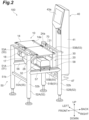
FIG. 2 is a perspective view of the weight inspection apparatus ofFIG. 1 . -
FIG. 3 is a side view (viewed from the upstream side) of the weight inspection apparatus ofFIG. 1 . -
FIG. 4 is an enlarged front view illustrating the vicinity of a conveyance weighing unit. -
FIG. 5 is a plan view of a frame and a conveyance weighing unit. -
FIG. 6 is a perspective view illustrating a state in which an intake conveyor unit and a weighing conveyor unit are removed. -
FIG. 7 is a perspective view of the frame. -
FIG. 8(a) is a view illustrating a sensor attachment structure in a first beam, andFIG. 8(b) is a view of the attachment structure inFIG. 8(a) as viewed from below the first beam. -
FIG. 9 is a front view illustrating a frame according to a modification and a conveyance weighing unit supported by the frame. -
FIG. 10 is a plan view of the frame. -
FIG. 11 is a sectional view of a base member. -
FIG. 12 is a perspective view illustrating a weighing unit fixed to the base member. - Hereinafter, a
weight inspection apparatus 100 according to an embodiment will be described with reference to the drawings. In the description of the drawings, the same elements are denoted by the same reference numerals, and redundant description will be omitted. In the following description, the terms "upper" and "lower" correspond to up-down directions in vertical directions as illustrated inFIG. 1 , and the terms "upstream" and "downstream" mean upstream and downstream in a conveyance direction TD of an object P to be inspected. - The
weight inspection apparatus 100 is an apparatus that checks whether the weight of the object P is within an allowable range while conveying the object P supplied from the upstream side to the downstream side. As illustrated inFIG. 1 , theweight inspection apparatus 100 mainly includes 1, amain body 40, and aframe 50. - A
conveyance weighing unit 20 is attached to theframe 50 and includes anintake portion 10 disposed on the upstream side (left side in the drawing) and aweighing device 30 disposed on the downstream side (right side in the drawing). - The
intake portion 10 of theconveyance weighing unit 20 receives and conveys the object P from the upstream side, and delivers the object P to the weighingdevice 30 on the downstream side. Theintake portion 10 includes an intake conveyor (intake conveyor unit) 11 and a drive unit 15. - The
intake conveyor 11 includes aconveyor frame 12, a drivingroller 13A, a drivenroller 13B, and a conveyingbelt 14. Theconveyor frame 12 is supported by a pair ofsupport members 61 disposed on the front side and the back side of theintake conveyor 11. The drivingroller 13A and the drivenroller 13B are rotatably attached to the upstream side and the downstream side of theconveyor frame 12 in the conveyance direction TD, respectively. The conveyingbelt 14 is an endless belt wound around the drivingroller 13A and the drivenroller 13B. - The drive unit 15 drives the
intake conveyor 11. The drive unit 15 includes adrive motor 16 and amotor box 17. Thedrive motor 16 rotates the drivingroller 13A. Themotor box 17 houses thedrive motor 16. Themotor box 17 is fixed to a base member 58 (to be described in detail later) of theframe 50 via thesupport member 61. Themotor box 17 may be directly fixed to thebase member 58 of theframe 50. Thedrive motor 16 transmits driving force to the drivingroller 13A via atiming belt 18 to rotate the drivingroller 13A. This causes the conveyingbelt 14 to rotate between the drivingroller 13A and the drivenroller 13B, and the object P on the conveyingbelt 14 is conveyed to theconveyance weighing unit 20. - The weighing
device 30 of theconveyance weighing unit 20 weighs the weight of the object P while conveying the object P delivered from theintake portion 10. The weighingdevice 30 includes aconveyance unit 20A and a weighingunit 20B. Theconveyance unit 20A conveys the object P. Theconveyance unit 20A includes a carryingconveyor 21 and adrive unit 25. - The conveyance direction TD of the carrying
conveyor 21 is a horizontal direction in the present embodiment, and is the same as the conveyance direction TD of theintake conveyor 11. The carryingconveyor 21 includes aconveyor frame 22, a drivingroller 23A and a drivenroller 23B, and a conveyingbelt 24. Theconveyor frame 22 is supported by a pair ofsupport members 62 disposed on the front side and the back side of theconveyance weighing unit 20. The drivingroller 23A and the drivenroller 23B are rotatably attached to the upstream side and the downstream side of theconveyor frame 22 in the conveyance direction TD, respectively. The conveyingbelt 24 is an endless belt wound around the drivingroller 23A and the drivenroller 23B. - The
drive unit 25 drives the carryingconveyor 21. Thedrive unit 25 includes adrive motor 26 and amotor box 27. Thedrive motor 26 rotates the drivingroller 23A. Themotor box 27 houses thedrive motor 26. Themotor box 27 is fixed to thebase member 58 of theframe 50 via thesupport member 62. Themotor box 27 may be directly fixed to thebase member 58 of theframe 50. Thedrive motor 26 transmits driving force to the drivingroller 23A via atiming belt 28 to rotate the drivingroller 23A. This causes the conveyingbelt 24 to rotate between the drivingroller 23A and the drivenroller 23B, and the object P on the conveyingbelt 24 is conveyed to the downstream side. - The weighing
unit 20B measures the weight of the object P on theconveyance unit 20A. The weighingunit 20B includes aload cell 31 and a weighingbox 32. Theload cell 31 detects a change in distortion caused by the object P being placed on theconveyance unit 20A, and it measures the weight of the object P placed on theconveyance unit 20A. The weighingbox 32 is fixed to thebase member 58 of theframe 50. The weighingbox 32 houses theload cell 31. - The
main body 40 is disposed behind the weighingdevice 30. Themain body 40 includes ahousing unit 41, acontrol unit 42, adisplay operation unit 43, and apower switch 44. Themain body 40 is fixed to alower beam portions 55 of theframe 50. - The
housing unit 41 is a vertically long housing extending in the up-down direction. Thecontrol unit 42 is housed in thehousing unit 41. Thecontrol unit 42 controls operation of each unit of theweight inspection apparatus 100. Thecontrol unit 42 includes, for example, a CPU, a ROM, a RAM, and the like. Thecontrol unit 42 receives a weighing signal output from theload cell 31 and determines whether the weighing value indicated by the weighing signal is within a predetermined allowable range. - The
display operation unit 43 is provided in an upper portion of thehousing unit 41. Ascreen 43a of thedisplay operation unit 43 displays contents related to measurement performed by the weighingdevice 30. For example, a result of determination by thecontrol unit 42 and the like are displayed on thescreen 43a of thedisplay operation unit 43. Thepower switch 44 turns on and off the power of theweight inspection apparatus 100. - Next, with reference to
FIGS. 1 to 5 and7 , the configuration of theframe 50 and the disposition relationship between each part of theframe 50 and each part of theconveyance weighing unit 20 will be described. As illustrated inFIGS. 1 to 3 , theframe 50 supports theconveyance weighing unit 20. That is, theframe 50 supports both theintake portion 10 and the weighingdevice 30. Theframe 50 includes foursupport columns weight inspection apparatus 100. The foursupport columns frame 50 includes a pair ofleft support columns 51 disposed on the upstream side and a pair ofright support columns 52 disposed on the downstream side. The pair ofleft support columns 51 is disposed so as to be separated from each other at a predetermined interval in a width direction (front-back direction) orthogonal to the conveyance direction TD. The pair ofright support columns 52 is disposed so as to be separated from each other at a predetermined interval in the width direction (front-back direction) orthogonal to the conveyance direction TD. The foursupport columns left support columns 51 and the interval between the pair ofright support columns 52 are, for example, equal, and theconveyance weighing unit 20 is housed within the range of the interval in the front-back direction. As illustrated inFIG. 5 , the foursupport columns conveyance weighing unit 20 in plan view. The foursupport columns support columns - In the following description, one of the pair of
left support columns 51 disposed on the front side may be referred to as aleft support column 51A, and one disposed on the back side may be referred to as aleft support column 51B. One of the pair ofright support columns 52 disposed on the front side may be referred to as aright support column 52A, and one disposed on the back side may be referred to as aright support column 52B. As described above, theleft support column 51A, theleft support column 51B, theright support column 52A, and theright support column 52B are parallel to each other, and extend, for example, in the up-down direction. In the present embodiment, the height (that is, the length) of each of theleft support column 51A, theleft support column 51B, theright support column 52A, and theright support column 52B is equal with respect to the installation surface F. - The
frame 50 includes a pair of upper beam portions (first beam portions) 53 and a pair oflower beam portions 55 connected to theleft support column 51 and theright support column 52 arranged in the conveyance direction TD. As illustrated inFIGS. 2 and7 , theupper beam portion 53 is connected to, for example, anupper end portion 51a of theleft support column 51 and anupper end portion 52a of theright support column 52. Thelower beam portion 55 is connected to, for example, alower portion 51b of theleft support column 51 and alower portion 52b of theright support column 52. Each of theupper beam portions 53 and thelower beam portion 55 is formed of, for example, a square tubular member made of metal. Both or one of theupper beam portions 53 and thelower beam portion 55 may be a member having a C-shaped section opened downward. On the lower surface of theupper beam portion 53, for example, anopening 53e extending in a longitudinal direction and a pair oflower surface pieces 53f forming theopening 53e are formed (seeFIG. 8(b) ). - In the following description, one of the pair of
upper beam portions 53 disposed on the front side may be referred to as anupper beam portion 53A, and one disposed on the back side may be referred to as anupper beam portion 53B. One of the pair oflower beam portions 55 disposed on the front side may be referred to as alower beam portion 55A, and one disposed on the back side may be referred to as alower beam portion 55B. Oneupper beam portion 53A and onelower beam portion 55A are fixed to theleft support column 51A and theright support column 52A arranged in the conveyance direction TD. Oneupper beam portion 53B and onelower beam portion 55B are fixed to theleft support column 51B and theright support column 52B arranged in the conveyance direction TD. Thehousing unit 41 of themain body 40 described above is attached to thelower beam portion 55B via abracket 47. Theupper beam portion 53A, theupper beam portion 53B, thelower beam portion 55A, and thelower beam portion 55B are parallel to each other and extend, for example, in the horizontal direction. Lengths of theupper beam portion 53A, theupper beam portion 53B, thelower beam portion 55A, and thelower beam portion 55B are equal to each other. - The
frame 50 includes one left horizontal beam portion (second beam portion) 56 connected to the pair ofleft support columns 51 arranged in the width direction (front-back direction) and one right horizontal beam portion (second beam portion) 57 connected to the pair ofright support columns 52 arranged in the width direction (front-back direction). The lefthorizontal beam portion 56 and the righthorizontal beam portion 57 are fixed to the center portions of theleft support column 51 and theright support column 52 in the up-down direction. Both the lefthorizontal beam portion 56 and the righthorizontal beam portion 57 extend horizontally and are located at a height between theupper beam portion 53 and thelower beam portion 55. The height of the lefthorizontal beam portion 56 is lower than the height of theleft support column 51A and lower than the height of theleft support column 51B. The height of the righthorizontal beam portion 57 is lower than the height of theright support column 52A and lower than the height of theright support column 52B. Each of the lefthorizontal beam portion 56 and the righthorizontal beam portion 57 is formed of, for example, a circular tubular member made of metal. The lefthorizontal beam portion 56 and the righthorizontal beam portion 57 are parallel to each other and extend, for example, in the horizontal direction. The length of the lefthorizontal beam portion 56 is equal to the length of the righthorizontal beam portion 57. The height of the lefthorizontal beam portion 56 is equal to the height of the righthorizontal beam portion 57. - The
frame 50 further includes thebase member 58 bridged between the lefthorizontal beam portion 56 and the righthorizontal beam portion 57. Thebase member 58 extends horizontally, for example. Thebase member 58 extends, for example, parallel to the installation surface F. Thebase member 58 is formed of, for example, a metal member having a C-shaped section opened downward. Thebase member 58 includes a flat topsurface plate portion 81. Themotor box 17 of the drive unit 15, themotor box 27 of thedrive unit 25, and the weighingbox 32 are fixed on the topsurface plate portion 81 of thebase member 58 using appropriate fastening members (bolt, nut, screw, or the like). The topsurface plate portion 81 is an attachment surface or an installation surface for attaching theconveyance weighing unit 20 to theframe 50. Arectangular opening 81e having an area of about 1/2 to 1/4 of the topsurface plate portion 81 is formed in a central region of the top surface plate portion 81 (see alsoFIG. 10 ). - The
upper beam portions 53, thelower beam portions 55, the lefthorizontal beam portion 56, and the righthorizontal beam portion 57 are connected to thesupport columns base member 58 is connected to the lefthorizontal beam portion 56 and the righthorizontal beam portion 57 by welding, for example. These connection forms are not limited to welding, and may be, for example, bonding or the like, or a fixing metal fitting or the like and a fastening member may be applied. - As illustrated in
FIG. 5 , in theframe 50, the two upper beam portions 53 (theupper beam portion 53A and theupper beam portion 53B), the lefthorizontal beam portion 56, and the righthorizontal beam portion 57 form a quadrangle in plan view. In plan view, theconveyance weighing unit 20 is disposed in the quadrangle (within a range) formed by the twoupper beam portions 53, the lefthorizontal beam portion 56, and the righthorizontal beam portion 57. More specifically, as illustrated inFIG. 6 , in plan view, themotor box 17, themotor box 27, and the weighingbox 32 are disposed in the quadrangle (within a range) formed by the twoupper beam portions 53, the lefthorizontal beam portion 56, and the righthorizontal beam portion 57. - More specifically, in the
frame 50, both the lefthorizontal beam portion 56 and the righthorizontal beam portion 57 are shorter than theupper beam portion 53. That is, the quadrangle formed by a frame-shaped beam portion including the four (four sides) of the pair ofupper beam portions 53, the lefthorizontal beam portion 56, and the righthorizontal beam portion 57 is a rectangle. The pair ofupper beam portions 53 is a pair of long-side beam portions forming long sides of the rectangle. The lefthorizontal beam portion 56 and the righthorizontal beam portion 57 are a pair of short-side beam parts forming short sides of the rectangle. The width direction is a direction in which the short-side beam portion extends, and corresponds to a "short-side direction" described in the claims. - As illustrated in
FIGS. 1 to 4 , theconveyance weighing unit 20 is supported by thebase member 58. That is, theintake portion 10 and the weighingdevice 30 are supported by thebase member 58. In other words, theconveyance weighing unit 20 is supported by the lefthorizontal beam portion 56 and the righthorizontal beam portion 57 via thebase member 58. - As illustrated in
FIGS. 1 and4 , aconveyance surface 14a of the conveyingbelt 14 of theintake conveyor 11 and aconveyance surface 24a of the conveyingbelt 24 of the carryingconveyor 21 are located at the same height. In other words, theconveyance surface 14a and theconveyance surface 24a are located on the same plane. The object P is delivered from theconveyance surface 14a to theconveyance surface 24a, and a gap portion X having a minute width (length in the conveyance direction TD) is formed between theintake conveyor 11 and the carryingconveyor 21. - The height of the
upper beam portion 53A connected to theupper end portion 51a of theleft support column 51A and theupper end portion 52a of theright support column 52A is equal to the height of theupper beam portion 53B connected to theupper end portion 51a ofleft support column 51B and theupper end portion 52a of theright support column 52B. In the present embodiment, the heights of theupper beam portion 53A and theupper beam portion 53B are the same as the heights of theconveyance surface 14a and theconveyance surface 24a. That is, when the installation surface F is assumed to be a flat plane, the distance from the installation surface F to upper end surfaces (upper ends) 53c of theupper beam portion 53A and theupper beam portion 53B is equal to the distance from the installation surface F to theconveyance surface 14a and theconveyance surface 24a. The upper end surfaces 53c of theupper beam portion 53A and theupper beam portion 53B are flush with the upper end surfaces of the twoleft support columns 51 and the tworight support columns 52. - In the
frame 50, four support columns, that is, theleft support columns 51 and theright support columns 52 are provided so as to surround theconveyance weighing unit 20. As illustrated inFIG. 5 , theconveyance weighing unit 20 is disposed between theright support column 52A and theupper beam portion 53B in the front-back direction. In plan view, theconveyance weighing unit 20 is disposed between the lefthorizontal beam portion 56 and the righthorizontal beam portion 57 in the left-right direction (conveyance direction TD). - As illustrated in
FIG. 2 , theupper beam portion 53A and theupper beam portion 53B are disposed on the side of the conveyingbelt 14 and the conveyingbelt 24. With this disposition, theupper beam portion 53A and theupper beam portion 53B, which are parts of theframe 50, serve as protection members for theintake conveyor 11 and the carryingconveyor 21. Conventionally, in a configuration in which theframe 50 is disposed below theconveyance weighing unit 20, a support arm extending in the front-back direction and the up-down direction is attached to a leg member having an inverted U shape, and a bumper member is provided at an upper end of the support arm. The bumper member extending in the conveyance direction plays a role of protecting the conveyance unit of the conveyance weighing unit. In theweight inspection apparatus 100 of the present embodiment, theupper beam portions 53 provided so as to bridge the upper ends (or upper portions) of the two support columns arranged in the conveyance direction TD protects theconveyance unit 20A (the carrying conveyor 21) of theconveyance weighing unit 20. A separate member such as the conventional support arm described above is unnecessary, and a part of theframe 50 has a bumper function. - As illustrated in
FIGS. 8(a) and 8(b) , for example, an electric system component or member can be attached to theupper beam portions 53. As an example, aphotoelectric sensor 70 may be attached to theupper beam portion 53B. Afixture 71 is fixed to the pair oflower surface pieces 53f through theopening 53e of theupper beam portion 53B, and thephotoelectric sensor 70 is fixed to aholder 72 integrated with thefixture 71. Thephotoelectric sensor 70 is disposed in the vicinity of the gap portion X between theintake conveyor 11 and the carryingconveyor 21, and detects the object P delivered from theintake conveyor 11 to the carryingconveyor 21. In addition to thephotoelectric sensor 70, various devices can be attached to theupper beam portions 53. For example, an emergency stop switch that can be operated by an operator may be provided. In consideration of operability, such an operation device is attached to theupper beam portion 53A on the front side of the pair ofupper beam portions 53. - As illustrated in
FIGS. 10 and11 , thebase member 58 includes the topsurface plate portion 81 forming an installation surface on which theconveyance weighing unit 20 is installed, and a pair of sidesurface plate portions 82 connected to both ends of the topsurface plate portion 81 in the width direction. Further, a lower surface between lower ends of the pair of sidesurface plate portions 82 is open, and anopen portion 85 is formed. The height of theopen portion 85 may be located, for example, within the range of the diameter of the right horizontal beam portion 57 (and the left horizontal beam portion 56). A pair ofbent plate portions 83 bent in the width direction (front-back direction) is formed at the lower end of the sidesurface plate portion 82. - In the
weight inspection apparatus 100, as illustrated inFIG. 12 , a base width W1 which is a size in the width direction of thebase member 58 is larger than a lower end width W2 which is a size in the width direction of the weighingbox 32 constituting the lower end of theconveyance weighing unit 20. The base width W1 may be equal to the lower end width W2. "The base width W1 is equal to the lower end width W2" includes a case where the base width W1 is the same as the lower end width W2, but also includes a case where the base width W1 is different from the lower end width W2, but the difference between them is very small. "The base width W1 is equal to the lower end width W2" has the same meaning as that the base width W1 is substantially equal to the lower end width W2. In such a case, the difference between the base width W1 and the lower end width W2 is less than 5% with respect to the lower end width W2. The base width W1 may be slightly smaller than the lower end width W2. - In the
base member 58, the base width W1 is constant. The base width W1 of thebase member 58 and a lower end width that is the size in the width direction of themotor box 17, which is the size in the width direction of the weighingbox 32 constituting the lower end of theconveyance weighing unit 20, also have the same magnitude relationship as described above (seeFIG. 3 ). - According to the
weight inspection apparatus 100 of the present embodiment, at least the fourbeam portions beam portions support columns frame 50 is increased. Vibration may adversely affect the measurement of the object P. Since the rigidity of theframe 50 is increased, theweight inspection apparatus 100 is less likely to be affected by vibration. In addition, it is also easy to reduce the weight of all or a part of the fourbeam portions frame 50. When it is necessary to separately provide a separate bumper portion as in the conventional case, the bumper portion interrupts weight reduction. In theweight inspection apparatus 100 of the present embodiment, since theframe 50 also serves as a bumper portion, weight reduction is realized. Also from the viewpoint of rigidity, it is difficult to twist (resistant to external force in a twisting direction). Devices can be attached to theupper beam portions 53 disposed at a high position, and operability for the operator is also improved. - The heights of the left
horizontal beam portion 56 and the righthorizontal beam portion 57 are lower than the heights of thesupport columns frame 50, which enhances stability. - The
conveyance weighing unit 20 is supported by the lefthorizontal beam portion 56 and the righthorizontal beam portion 57. Since theconveyance weighing unit 20 is supported at a lower position of theframe 50, the center of gravity of the entireweight inspection apparatus 100 is lowered, and the stability is enhanced. - In addition, since the
conveyance weighing unit 20 is supported by the lefthorizontal beam portion 56 and the righthorizontal beam portion 57 constituting short sides of the rectangle, theframe 50 can stably support theconveyance weighing unit 20. Further, resistance to vibration improves. - From another viewpoint, since the
conveyance weighing unit 20 is supported by the lefthorizontal beam portion 56 and the righthorizontal beam portion 57 which are the short-side beam portions, theframe 50 can stably support theconveyance weighing unit 20. Further, resistance to vibration improves. - Another problem inherent in the conventional weight inspection apparatus will be described. In the frame structure of the conventional weight inspection apparatus, the pair of leg members is connected by two rail-shaped members, and thus there has been a problem that torsion is likely to occur in the frame. A structure in which torsion is likely to occur may cause a decrease in rigidity of the frame and a decrease in weighing accuracy.
- According to the
weight inspection apparatus 100 of the present embodiment, thebase member 58 having the base width W1 equal to the lower end width W2 or larger than the lower end width W2 of theconveyance weighing unit 20 is bridged between the lefthorizontal beam portion 56 and the righthorizontal beam portion 57. Since thebase member 58 supports theconveyance weighing unit 20, torsion is less likely to occur than in a conventional structure in which two rail-shaped members are used. In addition, according to thebase member 58 having a large base width W1, rigidity is also secured. As a result of realizing the prevention of torsion and the increase in rigidity, the weighing accuracy also improves. - The
base member 58 includes the topsurface plate portion 81 forming an installation surface on which theconveyance weighing unit 20 is installed, and a pair of sidesurface plate portions 82 connected to both ends of the topsurface plate portion 81 in the width direction. A lower surface between lower ends of the sidesurface plate portions 82 is open. With this configuration, when theframe 50 is cleaned with water, water is less likely to accumulate in thebase member 58. Since it is excellent in drainage performance (drainage), it is easy to maintain a dry state. - The
bent plate portion 83 bent inward in the width direction is formed at a lower end of the sidesurface plate portion 82. Thebase member 58 is not only excellent in drainage performance at the time of cleaning, but also the strength of thebase member 58 is further increased by thebent plate portion 83. - The top
surface plate portion 81 is provided with theopening 81e that overlaps a position below the gap portion X in the conveyance direction TD. When theframe 50 is cleaned with water, water drops from between themotor box 17 provided below theintake conveyor 11 and themotor box 27 provided below the carryingconveyor 21, but the water can be quickly discharged (dropped) without being retained by thebase member 58. In addition, accumulation of dust on thebase member 58 can also be reduced. - Although the embodiments of the present disclosure have been described above, the present invention is not limited to the above embodiments. For example, in the above embodiment, the case where the heights of the
upper beam portion 53A and theupper beam portion 53B are the same as the heights of theconveyance surface 14a and theconveyance surface 24a has been exemplified, but the present invention is not limited to this example. As illustrated inFIG. 9 , aframe 50A in which the heights of theupper beam portion 53A and theupper beam portion 53B are higher than the heights of theconveyance surface 14a and theconveyance surface 24a may be adopted. - In the above embodiment, the case where the first beam portion is longer than the second beam portion has been exemplified. That is, the case where the first beam portion is the long-side beam portion and the second beam portion is the short-side beam portion has been exemplified, but the present invention is not limited to this example. The second beam portion may be longer than the first beam portion. That is, the second beam portion may be the long-side beam portion, and the first beam portion may be the short-side beam portion. In such a case, the conveyance weighing unit may be supported by the second beam portion, but it does not have to be supported by the second beam portion. The conveyance weighing unit may be supported by the first beam portion as the short-side beam portion. An appropriate bracket is fixed to the first beam portion, and the conveyance weighing unit is supported by the bracket. The bracket may be provided at a position lower than the upper end of the first beam portion and fixed to the lower portion or the lower surface of the conveyance weighing unit.
- The height of the second beam portion may be the same as the height of the support column or higher than the height of the support column. In such a case, the second beam portion may be disposed at a position that does not interfere with the conveyance weighing unit so as not to interrupt the function of the conveyance weighing unit.
- The height of the
upper beam portion 53A and the height of theupper beam portion 53B may be different. In such a case, the height of the upper end of only one of the pair ofupper beam portions 53 may be the same as the height of theconveyance surface 24a of theconveyance weighing unit 20 or may be higher than the height of theconveyance surface 24a. The other upper end of the pair of first beam portions may be lower than the height of theconveyance surface 24a of theconveyance weighing unit 20. That is, the height of the upper end of at least one of theupper beam portions 53 may be equal to the height of theconveyance surface 24a of theconveyance weighing unit 20 or higher than the height. - Various modified modes may be adopted for the configuration of the conveyance weighing unit. For example, a configuration in which a weighing box is incorporated in the conveyance unit may be adopted.
- The gap portion X may be omitted. The pair of
bent plate portions 83 may be omitted. As thebase member 58, a mode having various sections may be adopted, but the base width W1 of thebase member 58 has the above-described relationship with respect to the lower end width W2 of theconveyance weighing unit 20. - Various modified modes may be adopted for the configuration of the conveyance weighing unit. For example, a configuration in which a weighing box is incorporated in the conveyance unit may be adopted. In such a case as well, the base width W1, which is the size in the width direction of the
base member 58, is equal to the lower end width W2, which is the size in the width direction of the lower end of theconveyance weighing unit 20, or larger than the lower end width W2. - The
intake portion 10 may be omitted. In such a case, theframe 50 may support only the weighingdevice 30. In theframe 50, thelower beam portions 55 may be omitted. - The quadrangle formed by the four beam portions in plan view may be a square.
- 10 intake portion
- 11 intake conveyor (intake conveyor unit)
- 20 conveyance weighing unit
- 20B weighing unit
- 21 carrying conveyor (weighing conveyor unit)
- 50 frame
- 51, 51A, 51B left support column
- 52, 52A, 52B right support column
- 53, 53A, 53B upper beam portion (first beam portion)
- 55, 55A, 55B lower beam portion
- 56 left horizontal beam portion (second beam portion, short-side beam portion)
- 57 right horizontal beam portion (second beam portion, short-side beam portion)
- 58 base member
- 81 top surface plate portion
- 82 side surface plate portion
- 83 bent plate portion
- F installation surface
- TD conveyance direction
- P object to be inspected
- W1 base width
- W2 lower end width
- X gap portion
Claims (8)
- A weight inspection apparatus comprising:a conveyance weighing unit configured to measure a weight of an object to be inspected while conveying the object in a conveyance direction; anda frame configured to support the conveyance weighing unit,whereinthe frame includes:at least four support columns configured to be disposed at positions not overlapping with the conveyance weighing unit in plan view; andat least four beam portions configured to form a quadrangle in plan view, each of the at least four beam portions being configured to be connected to any two of the support columns, andthe beam portions include a pair of first beam portions, each of the pair of first beam portions being configured to be connected to two support columns arranged in the conveyance direction, and a height of an upper end of at least one of the first beam portions being configured to be equal to a height of a conveyance surface of the conveyance weighing unit or higher than the height of the conveyance surface.
- The weight inspection apparatus according to claim 1, wherein
the beam portions include a pair of second beam portions, each of the pair of second beam portions being configured to be connected to two support columns arranged in a width direction orthogonal to the conveyance direction, and a height of the second beam portions being configured to be lower than a height of the two support columns. - The weight inspection apparatus according to claim 2, wherein the conveyance weighing unit is configured to be supported by the second beam portions.
- The weight inspection apparatus according to claim 3, wherein the second beam portions are shorter than the first beam portions.
- The weight inspection apparatus according to claim 1 or 2, whereinthe beam portions include a pair of long-side beam portions forming long sides of the quadrangle and a pair of short-side beam portions forming short sides of the quadrangle, andthe conveyance weighing unit is configured to be supported by the short-side beam portions.
- The weight inspection apparatus according to any one of claims 1 and 3 to 4, whereinthe frame includes:at least two second beam portions included in the beam portions, each of the at least two second beam portions being configured to be connected to two support columns arranged in a width direction orthogonal to the conveyance direction among the support columns; anda base member configured to be bridged between the at least two second beam portions and support the conveyance weighing unit, anda base width that is a size in the width direction of the base member is equal to or larger than a lower end width that is a size in the width direction of a lower end of the conveyance weighing unit.
- The weight inspection apparatus according to claim 2, whereinthe frame includes a base member configured to be bridged between the pair of second beam portions and support the conveyance weighing unit, anda base width that is a size in the width direction of the base member is equal to or larger than a lower end width that is a size in the width direction of a lower end of the conveyance weighing unit.
- The weight inspection apparatus according to claim 5, whereinthe frame includes a base member configured to be bridged between the pair of short-side beam portions and supports the conveyance weighing unit, anda base width that is a size of the base member in a direction of the short sides is equal to or larger than a lower end width that is a size of a lower end of the conveyance weighing unit in a direction of the short sides .
Applications Claiming Priority (3)
| Application Number | Priority Date | Filing Date | Title |
|---|---|---|---|
| JP2022008770A JP7733914B2 (en) | 2022-01-24 | 2022-01-24 | Weight Inspection Equipment |
| JP2022008774A JP7752867B2 (en) | 2022-01-24 | 2022-01-24 | Weight Inspection Equipment |
| PCT/JP2023/001545 WO2023140328A1 (en) | 2022-01-24 | 2023-01-19 | Weight inspection device |
Publications (2)
| Publication Number | Publication Date |
|---|---|
| EP4471386A1 true EP4471386A1 (en) | 2024-12-04 |
| EP4471386A4 EP4471386A4 (en) | 2026-01-21 |
Family
ID=87348319
Family Applications (1)
| Application Number | Title | Priority Date | Filing Date |
|---|---|---|---|
| EP23743321.4A Pending EP4471386A4 (en) | 2022-01-24 | 2023-01-19 | WEIGHT TESTER |
Country Status (4)
| Country | Link |
|---|---|
| US (1) | US20250180394A1 (en) |
| EP (1) | EP4471386A4 (en) |
| KR (1) | KR20240135839A (en) |
| WO (1) | WO2023140328A1 (en) |
Family Cites Families (7)
| Publication number | Priority date | Publication date | Assignee | Title |
|---|---|---|---|---|
| JPS5064973U (en) | 1973-10-15 | 1975-06-12 | ||
| JP2002131117A (en) * | 2000-10-26 | 2002-05-09 | Ishida Co Ltd | Weighing device |
| JP5064973B2 (en) | 2007-11-02 | 2012-10-31 | 株式会社イシダ | Weight inspection device |
| DE102013203457B4 (en) * | 2013-02-28 | 2024-06-20 | Bizerba SE & Co. KG | Frame of a weighing conveyor |
| CN107521758A (en) * | 2017-09-27 | 2017-12-29 | 黄石市友创科技股份有限公司 | A kind of belt conveyer scale of vacuum corn tabletting packing machine |
| JP2019113315A (en) * | 2017-12-20 | 2019-07-11 | 大和製衡株式会社 | Weighing device |
| JP7545715B2 (en) * | 2020-08-05 | 2024-09-05 | 株式会社イシダ | Weight Inspection Equipment |
-
2023
- 2023-01-19 EP EP23743321.4A patent/EP4471386A4/en active Pending
- 2023-01-19 KR KR1020247027747A patent/KR20240135839A/en active Pending
- 2023-01-19 WO PCT/JP2023/001545 patent/WO2023140328A1/en not_active Ceased
- 2023-01-19 US US18/729,133 patent/US20250180394A1/en active Pending
Also Published As
| Publication number | Publication date |
|---|---|
| US20250180394A1 (en) | 2025-06-05 |
| KR20240135839A (en) | 2024-09-12 |
| EP4471386A4 (en) | 2026-01-21 |
| WO2023140328A1 (en) | 2023-07-27 |
Similar Documents
| Publication | Publication Date | Title |
|---|---|---|
| CN106716084B (en) | Combination metering device | |
| CN101802569B (en) | Weight inspection device | |
| JP2000086114A (en) | Elevator equipment | |
| JP2019113315A (en) | Weighing device | |
| US5262598A (en) | Weigh hopper supported by a 3-point suspension with a tension load cell | |
| US20250180394A1 (en) | Weight inspection device | |
| JP7733914B2 (en) | Weight Inspection Equipment | |
| JP7752867B2 (en) | Weight Inspection Equipment | |
| JP5080939B2 (en) | Quality inspection equipment | |
| JP4156786B2 (en) | Quality inspection equipment | |
| US12434869B2 (en) | Bagmaking and packaging apparatus and weighing and packaging system | |
| JP2003149039A (en) | Weighing support structure for large-sized silo | |
| JP7094617B2 (en) | Weighing device | |
| KR101137422B1 (en) | Pipe Conveyor Scale | |
| TWI438106B (en) | Vehicle with load weight meter and assembly method for the same | |
| JP6987451B2 (en) | Weight sorter | |
| US12509330B2 (en) | Elevator car and elevator | |
| JPS628502Y2 (en) | ||
| JP7415514B2 (en) | Stand and image display system | |
| JP6147483B2 (en) | Weighing device | |
| JP2002039845A (en) | Weighing device | |
| CN203241129U (en) | Dynamometer weighing module | |
| JP2023107317A (en) | weight checker | |
| JP2024134238A (en) | Weight Inspection Equipment | |
| JP2015064360A (en) | Vehicle with payload meter and assembling method thereof |
Legal Events
| Date | Code | Title | Description |
|---|---|---|---|
| STAA | Information on the status of an ep patent application or granted ep patent |
Free format text: STATUS: THE INTERNATIONAL PUBLICATION HAS BEEN MADE |
|
| PUAI | Public reference made under article 153(3) epc to a published international application that has entered the european phase |
Free format text: ORIGINAL CODE: 0009012 |
|
| STAA | Information on the status of an ep patent application or granted ep patent |
Free format text: STATUS: REQUEST FOR EXAMINATION WAS MADE |
|
| 17P | Request for examination filed |
Effective date: 20240820 |
|
| AK | Designated contracting states |
Kind code of ref document: A1 Designated state(s): AL AT BE BG CH CY CZ DE DK EE ES FI FR GB GR HR HU IE IS IT LI LT LU LV MC ME MK MT NL NO PL PT RO RS SE SI SK SM TR |
|
| DAV | Request for validation of the european patent (deleted) | ||
| DAX | Request for extension of the european patent (deleted) | ||
| A4 | Supplementary search report drawn up and despatched |
Effective date: 20251218 |
|
| RIC1 | Information provided on ipc code assigned before grant |
Ipc: G01G 11/00 20060101AFI20251212BHEP Ipc: G01G 21/28 20060101ALI20251212BHEP |