EP4471384A1 - Gerät zur überwachung von eigenschaften von oder in elektrischen anlagen, halter dafür und gateway-gerät für solche geräte, elektrische anlage mit solchem gerät und solchem gateway-gerät und entsprechende verfahren zur installation und betrieb - Google Patents
Gerät zur überwachung von eigenschaften von oder in elektrischen anlagen, halter dafür und gateway-gerät für solche geräte, elektrische anlage mit solchem gerät und solchem gateway-gerät und entsprechende verfahren zur installation und betrieb Download PDFInfo
- Publication number
- EP4471384A1 EP4471384A1 EP23315223.0A EP23315223A EP4471384A1 EP 4471384 A1 EP4471384 A1 EP 4471384A1 EP 23315223 A EP23315223 A EP 23315223A EP 4471384 A1 EP4471384 A1 EP 4471384A1
- Authority
- EP
- European Patent Office
- Prior art keywords
- gateway
- holder
- housing
- interface
- accordance
- Prior art date
- Legal status (The legal status is an assumption and is not a legal conclusion. Google has not performed a legal analysis and makes no representation as to the accuracy of the status listed.)
- Pending
Links
Images






Classifications
-
- G—PHYSICS
- G01—MEASURING; TESTING
- G01D—MEASURING NOT SPECIALLY ADAPTED FOR A SPECIFIC VARIABLE; ARRANGEMENTS FOR MEASURING TWO OR MORE VARIABLES NOT COVERED IN A SINGLE OTHER SUBCLASS; TARIFF METERING APPARATUS; MEASURING OR TESTING NOT OTHERWISE PROVIDED FOR
- G01D11/00—Component parts of measuring arrangements not specially adapted for a specific variable
- G01D11/30—Supports specially adapted for an instrument; Supports specially adapted for a set of instruments
-
- G—PHYSICS
- G01—MEASURING; TESTING
- G01D—MEASURING NOT SPECIALLY ADAPTED FOR A SPECIFIC VARIABLE; ARRANGEMENTS FOR MEASURING TWO OR MORE VARIABLES NOT COVERED IN A SINGLE OTHER SUBCLASS; TARIFF METERING APPARATUS; MEASURING OR TESTING NOT OTHERWISE PROVIDED FOR
- G01D21/00—Measuring or testing not otherwise provided for
-
- H—ELECTRICITY
- H04—ELECTRIC COMMUNICATION TECHNIQUE
- H04Q—SELECTING
- H04Q9/00—Arrangements in telecontrol or telemetry systems for selectively calling a substation from a main station, in which substation desired apparatus is selected for applying a control signal thereto or for obtaining measured values therefrom
-
- H—ELECTRICITY
- H04—ELECTRIC COMMUNICATION TECHNIQUE
- H04W—WIRELESS COMMUNICATION NETWORKS
- H04W4/00—Services specially adapted for wireless communication networks; Facilities therefor
- H04W4/30—Services specially adapted for particular environments, situations or purposes
- H04W4/38—Services specially adapted for particular environments, situations or purposes for collecting sensor information
Definitions
- the present invention relates to an apparatus for monitoring properties of and in electrical installations, in particular for monitoring the temperature, humidity, COV and the like, of electrical components in cabinets.
- the present invention further relates to a gateway-device providing connectivity with the apparatus, and to methods of installing and operating the apparatus and the gateway-device.
- Electrical high-power distribution installations are widely used in manufacturing and commercial sites, factories, hospitals, malls and other public and private infrastructure. These high-power distribution installations are normally secured in closed cabinets to prevent accidental contact with electricity-carrying elements, which could cause severe injury or death, and interruption of the power supply. Electrical high-power distribution installations may distribute high-voltages or high currents. In the following the expression high-power distribution installation is used for any of those variants.
- a major threat to continuous and interruption-free operation of high-power electrical installations is found in adverse evolution of enclosure parameters or settings, such as thermal overheating, e.g., due to the high currents flowing and the rather limited convective and radiation cooling provided in closed cabinets, arcing, mechanical vibrations, humidity, presence of foreign objects and animals in the enclosure, and the like. While cooling can be improved by adding forced air flows, local overheating of conductors may still be possible, notably at junctions, interrupters, and suspension points. Likewise, faulty installation, e.g., by loose screw connections, and aging of components may increase the likelihood of overheating, arcing and sensitivity to humidity or mechanical vibration. Overheating may damage or even destroy the high-power electrical installation, which may result in injury to operating personnel, and adversely affect the operation of manufacturing sites or factories.
- thermal overheating e.g., due to the high currents flowing and the rather limited convective and radiation cooling provided in closed cabinets, arcing, mechanical vibrations, humidity, presence of foreign objects and
- inspections at regular intervals cannot reveal any spurious event, including but not limited to foreign objects that may have entered the enclosure, such as insects or small animals, causing an abnormal situation prior to being annihilated and possibly disappearing when being annihilated.
- a visual inspection or an inspection using a thermographic camera is performed, the enclosure must be opened. Opening the enclosure can change the thermal distribution within the enclosure, preventing detection of thermal situations that are present in a closed enclosure.
- an object of the present invention to propose an apparatus for periodically or continuously sensing properties of and in electrical installations, and a holder for mounting the apparatus in electrical installations.
- a further object of the present invention is to propose a gateway device for communicating with the apparatus, for monitoring the electrical installation.
- Yet further objects of the present invention are to provide a system comprising one or more apparatus and holders, as well as a gateway device, and an electrical installation comprising such system.
- Yet a further object of the present invention is to provide a method of installing and operating the sensing apparatus, the gateway, and the system, respectively.
- a portion of the section adapted for insertion protrudes into the housing through the opening.
- adapted for insertion may comprise matching size and shape and may also comprise a feature limiting insertion depth.
- the mechanical interface is further arranged to provide access and/or functional contact, of the coupling section of the holder coupled with the housing, with the at least one sensor.
- the coupling section of the holder received in the opening in the housing gains access to and can establish functional contact with the sensor.
- functional contact may refer to a contact that transfers the property measured by the sensor, i.e., the mechanical interface between the holder and the apparatus may act as a conducting element for the measured property.
- the opening may be positioned to permit the coupling section of the holder received in the housing to come into contact with a surface of the sensor, acting as a thermal conductor.
- additional means may be provided for establishing or improving the functional contact, in the previous example, e.g., thermal conductive paste or pads, or the like.
- Other means may be structural in nature, e.g., resilient or flexible structures or elements that ensure proper contact between the sensor and the mechanical interface. It is obvious that the mechanical interface may also be adapted to provide access and/or functional contact with sensors that are located at an outer surface of the housing.
- the apparatus may further comprise a microprocessor, volatile and non-volatile memory.
- the non-volatile memory stores computer program instructions which, when executed by the microprocessor in the volatile memory, configure the apparatus to execute one or more steps of methods in accordance with the sixth and/or seventh aspect of the invention described further below.
- the mechanical interface is arranged to provide access, and/or contact, of the first wireless interface to an antenna provided on or with the holder, through the coupling section of the holder received in the housing.
- This feature may be advantageous in case the housing shields electromagnetic radiation, preventing the proper functioning of an antenna if it were located inside the housing, or in case the housing of the apparatus needs to be oriented in a way that an internal antenna has a sub-optimal orientation towards a gateway device it communicates with.
- the holder can establish a connection for the first wireless interface to a ground plane or ground connection, e.g., for an antenna that may be located inside the housing.
- the housing further comprises an indicator configurable to indicate a property of a wireless connectivity established with the first wireless interface.
- the indicator may be implemented as an indicator light, which lights up whenever field strength of the wireless connection exceeds a predetermined threshold. A sufficiently high field strength may be used as an indication that a data connection will likewise be properly operative.
- the at least one attachment element is arranged to receive and be removably locked onto a structural element of the electrical installation, or to be removably attached to a surface thereof.
- Locking onto or attaching may comprise applying mutually opposing forces onto the structural element, i.e., clamping, or using magnetic force, but also interlocking elements or removable adhesives.
- the interlocking elements may be arranged to form-fit with structural elements, e.g., heads of screws, or nuts of the electrical installation.
- the at least one attachment element comprises two attachment sections extending from opposite ends of a connecting section. At least one of the attachment sections is arranged to lock onto the structural element of the electrical installation and/or provided with means for exerting a force acting towards the respective other attachment section.
- the means may, e.g., comprise a screw, or generally at least partially resilient and flexible attachment sections.
- the holder at least a portion of the coupling section adapted for coupling with the interface of the housing, or of a part or an element of the holder connecting the attachment element and the coupling section adapted for coupling with the interface of the housing, is manually deformable or movable.
- the coupling section may be configured to movably couple with the mechanical interface of the housing or with a mechanical coupling structure of a coupling element to which the housing is ultimately mounted. This advantageously permits orienting an apparatus held by the holder for improving a wireless connection with a gateway device and/or for placing the sensor of the apparatus in a position that improves sensing of a property.
- the coupling section adapted for coupling with the interface of the housing is arranged to transfer or conduct a monitored property from outside of the housing to the at least one sensor inside of the housing.
- the holder may conduct heat from a mounting point of the holder in an electrical installation to a sensor inside the housing.
- Other variants may accomplish transferring or conducting a measured property by using a conducting element, e.g., conduct light by means of optical fibres, or humidity or liquids by means of a wick-like structure provided on or in the holder.
- Heat transfer may be improved by using a corresponding conducting element, which may even comprise a heat shield that improves the accuracy and response time. Transferring or conducting a measured property may advantageously decouple the orientation of the housing from the attachment point, which may, inter alia, be used for obtaining an improved wireless connection.
- the proposed apparatus can be easily installed in different locations of an electrical installation.
- the easy and flexible installation of the sensors facilitates placing sensors in critical areas, which may be different depending on each electrical installation. This also permits easy retrofitting or upgrading of existing electrical installations, which are often operated over several decades, and which may not have been equipped with sensors at the time of initial commissioning.
- a gateway-device cooperating with one or more apparatus in accordance with the first aspect of the invention comprises a microprocessor, volatile and non-volatile memory, and a second wireless interface that is adapted to provide electrical energy to first wireless interfaces of one or more of such apparatus.
- the non-volatile memory stores computer program instructions which, when executed by the microprocessor in the volatile memory, configure the gateway-device to execute methods in accordance with the sixth and/or seventh aspects of the invention.
- the gateway-device is provided with two or more antennas coupled to the second wireless interface, and wherein the gateway device is configured to perform beamforming for directionally transmitting energy and data, and for directionally or non-directionally receiving data. Beamforming may, for example, be used for selectively communicating with one of a plurality of apparatus according to the first aspect of the invention.
- the gateway-device comprises a third interface, wire or wireless, configured for communicating with a mobile device operable to make available at least an information correlated to a field strength or a quality of a wireless connection between the first interface of the apparatus according to the first aspect of the invention and the second interface of the gateway-device according to the third aspect of the invention.
- Making available may comprise providing information on a display and/or providing acoustic information.
- a system for monitoring properties of and in electrical installations comprises at least one apparatus in accordance with the first aspect of the invention, and further comprises a gateway-device in accordance with the third aspect of the invention.
- the system may further comprise a holder in accordance with the second aspect of the invention.
- an electrical installation comprises a system in accordance with the fourth aspect of the invention.
- a method of installing an apparatus in accordance with the first aspect of the invention in an electrical installation comprises positioning the apparatus in or next to a location in the electrical installation, in which a property of or in the electrical installation is to be monitored and providing, via a second interface of a gateway-device in accordance with the third aspect of the invention, electrical energy to the apparatus, which receives the electrical energy via its first wireless interface.
- the method further comprises determining, in the apparatus or in the gateway-device, a field strength and/or a quality of the wireless connection and providing, by the apparatus or by or via the gateway-device, an providing an indication whenever the field strength and/or the quality of the wireless connection exceeds a predetermined value or level.
- the method further comprises modifying an orientation of the apparatus and/or a holder in accordance with the second aspect of the invention in the electrical installation and/or modifying the position of the apparatus and/or the holder in the electrical installation, until the field strength and/or the quality of the wireless connection between the apparatus and the gateway-device, exceeds the predetermined value or level. While modifying the indication is monitored for identifying a location and/or orientation which provides a satisfactory wireless connection.
- the indication is provided via the gateway-device
- the indication is provided by an indicator provided with the gateway-device.
- the indication is forwarded, by the third interface, to a further device that is provided with a corresponding indicator, e.g., an optical indicator element or an indicator shown on a display.
- Wirelessly transmitting electrical energy and data may comprise controlling two or more antennas of the gateway-device to perform a beamforming operation, for directionally transmitting and receiving.
- the methods of transmitting and/or receiving may be represented by computer program instructions which, when executed by a microprocessor in an associated volatile memory, configure the microprocessor and/or control hardware components of an apparatus or of a gateway device as presented hereinbefore, respectively, to execute one or more steps of the method of installing or of the method of operating as presented hereinbefore, respectively.
- the computer program instructions may be retrievably stored or transmitted on a computer-readable medium or data carrier.
- the medium or the data carrier may by physically embodied, e.g., in the form of a hard disk, solid state disk, flash memory device or the like.
- the medium or the data carrier may also comprise a modulated electro-magnetic, electrical, or optical signal that is received by computer by means of a corresponding receiver, and that is transferred to and stored in a memory of the computer.
- the invention advantageously provides a means for continuously monitoring properties of electrical installations, and also permits retrofitting existing electrical installations with little effort. Precise monitoring of the behaviour of components in the enclosure also permits gaining insight that enables reducing the size of enclosures or modifying the layout thereof in future electrical installations, while still complying with normative requirements.
- FIG. 1 shows a simplified block diagram of an exemplary apparatus 100 in accordance with the first aspect of the invention.
- a sensor 104, a first wireless interface 106, an antenna 108, a microprocessor 110, volatile memory 112 and non-volatile memory 114 are connected via one or more signal or data lines or buses 116.
- the aforementioned elements are arranged in a housing 102, which has a mechanical interface 118, e.g., an opening.
- Mechanical interface 118 is adapted to be coupled with a coupling section 210 of a holder 200 (not shown in the figure).
- Holder 200 is the sole mechanical mounting point of the housing 102.
- Sensor 104 and/or antenna 108 may be arranged close to the mechanical interface 118 and may be in electrical or other contact with holder 200 or a section or portion thereof (not shown in the figure).
- An identification may be provided external to the housing, e.g., identifier 120 that can be read out optically or visually, or by any other means. Alternatively, the identifier may be read out wirelessly, e.g., in the form of an NFC tag or the like.
- the identifier 120 may be separate from other electronic or functional components of the apparatus 100 and may be logically linked to the other electronic or functional components of the apparatus 100 through a reference list or look-up table.
- an indicator 122 may be provided for indicating a property of a wireless connection established with the first wireless interface 106, e.g., a light emitting element that lights up when the apparatus receives sufficient electrical energy for operation via the first wireless interface 106.
- Figure 2 shows an exemplary housing 102 of the apparatus 100 in accordance with the first aspect of the invention.
- the exemplary housing 102 shown in the figure has a shape of a general parallelepiped, although other shapes are likewise possible.
- Exemplary housing 102 has a mechanical interface 118, in the figure in the form of an opening, that is adapted to be coupled with a section of a holder 200 (not shown in the figure). It is obvious that the mechanical interface may take other forms or shapes.
- FIG 3 shows various views of a first exemplary embodiment of a holder 200 in accordance with the second aspect of the invention.
- the holder has an attachment element 202 which, in this embodiment, has the general form of a clamp or a bracket, i.e., comprises two opposed sections 204 are connected by a bridge section 206.
- the opposed sections 204 may each form one essentially single section, as visible in figure 3 a) , or may comprise multiple subsections acting together, as shown in figures 3 c) and d ).
- the holder 200 is preferably made from a resilient material, e.g., metal or plastic, and the bridge section 206 is dimensioned so as to permit attachment of the holder 200 onto a bar-like structure that has similar dimensions.
- the ends of the opposed sections 204 may be bent away from each other, facilitating positioning the holder over the bar-like structure. Portions of the opposed 204 sections may be bent towards the respective other section, providing a locking element 208.
- a coupling section 210 adapted for coupling with the mechanical interface 118 of housing 102 of the apparatus 100 extends from the bridge section 206. This coupling section 210 may be at last partially deformable, e.g., for adjusting the orientation of the apparatus 100 once it is mounted on the holder 200. To this end the coupling section 210 may have a part having a reduced width or diameter, which reduces the force required for orienting the apparatus 100 mounted on the holder 200.
- a further solution permitting adjusting the orientation of the apparatus 100 is shown with reference to figures 9 to 19 further below.
- Figure 4 shows an exemplary apparatus 100 in accordance with the first aspect of the invention mounted on the first exemplary embodiment of a holder 200 in accordance with the second aspect of the invention shown in figure 3 .
- Coupling section 210 of holder 200 is coupled with the interface 118 of housing 102, i.e., inserted into the opening, leaving the opposed sections 204 of the holder visible and accessible.
- FIG. 5 shows various views of a second exemplary embodiment of a holder 200 in accordance with the second aspect of the invention.
- the holder 200 has an attachment element 202 that is configured to be placed on a protrusion, e.g., a bolt or a screw head or thread.
- the attachment element 202 has a recess 220 that is configured to receive such bolt or screw head or thread.
- the recess 220 may have a circular shape, permitting a rotation on the screw head or thread, or bolt received therein, thus facilitating orientation of the apparatus 100 mounted on the holder 200.
- the diameter of the recess 220 may correspond to the largest dimension of the bolt or screw head or thread, for providing proper fixture, or may be slightly smaller than the largest dimension of the bolt or screw head.
- the holder 200 is preferably made from an elastic or at least plastic material or has elastic or plastic features for receiving the bolt or screw head.
- a thread may be provided in the recess 220 that matches a thread of a screw on which the holder is to be mounted.
- the holder 200 of figure 5 has a coupling section 210 adapted for coupling with the interface 118 of housing 102 of the apparatus 100.
- Figure 6 shows an exemplary apparatus 100 in accordance with the first aspect of the invention mounted on the second exemplary embodiment of a holder 200 in accordance with the second aspect of the invention shown in figure 5 .
- coupling section 210 of holder 200 is coupled with the interface 118 of housing 102, i.e., inserted into the opening, leaving the attachment element 202 of the holder visible and accessible.
- the holder is placed on a screw head.
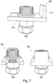
- FIG. 7 shows various views of a third exemplary embodiment of a holder 200 in accordance with the second aspect of the invention.
- the attachment element 202 of the holder has two prongs spaced apart from each other which provide a cut-out that may receive a screw shaft or the like.
- the attachment element 202 may be fixed using the screw or a nut mounted thereon, preferably using washers for preventing damaging the holder and enlarging the area of contact. It is also possible to use a rivet or similar mounting element to fix the holder 200 to a structure.
- the holder of figure 7 has a coupling section 210 adapted for coupling with the interface 118 of housing 102 of the apparatus 100.
- Figure 8 shows an exemplary apparatus 100 in accordance with the first aspect of the invention mounted on the third exemplary embodiment of a holder 200 in accordance with the second aspect of the invention shown in figure 7 .
- coupling section 210 of holder 200 is coupled with the interface 118 of housing 102, i.e., inserted into the opening, leaving the attachment element 202 of the holder visible and accessible.
- FIG 9 shows an exploded view of a fourth exemplary embodiment.
- the attachment element 202 of the holder corresponds, in principle, to the one shown in figure 5 , i.e., attachment element 202 is configured to be placed on a protrusion, e.g., a bolt or a screw head or thread. Details of the attachment element 202 will be provided further below.
- a first mechanical coupling structure 230 here a ball head, is connected with the attachment element 202.
- the first mechanical coupling structure 230 is configured to couple with a corresponding second mechanical coupling structure 142, which may be a part of the interface 118 of the housing 102 of the apparatus 100, or of a separate coupling element 140 that is affixable to the housing 102 of the apparatus.
- the coupling element 140 shown in the figure comprises the second mechanical coupling structure 142 that is shaped for proper coupling with the first mechanical coupling structure 230, i.e., is shaped to receive and hold the ball head exemplarily shown in the figure, and a third mechanical coupling structure 146 that is shaped for mechanically interfacing with and holding the housing 102 of an apparatus 100 or a support element 160, to which the housing 102 can be mounted, e.g., via adhesives or screws. Accordingly, the support element 160 or the housing 102 have corresponding fourth mechanical coupling structures that are shaped for attaching to or interfacing with the third mechanical coupling structure 146.
- the third mechanical coupling structure 146 may comprise resilient snap hooks that engage with rims, ridges or recesses of the housing 102 or the support element 160, which may form or be part of the fourth mechanical coupling structure.
- Figure 10 shows a first oblique side view of the attachment element 202 and the first mechanical coupling structure 230 of figure 9 .
- an external hexagonal section 222 is visible, which may internally have a corresponding hexagonal shape for coupling with a hexagonal screw head or nut to which the holder 200 is mounted.
- a wrench may be used for tightening and/or loosening the screw or nut, or for checking proper fastening torque thereof.
- a securing arrangement 224 is provided for securely fixing the attachment element 202 to the screw or nut.
- Figure 11 shows a second perspective view of the attachment element 202 and the first mechanical coupling structure 230 of figure 9 .
- the external hexagonal section 222 is better visible.
- an indicator 226 is shown, which may be used for indicating any unwanted change in the position of the holder 200 or the attachment element 202, and/or a loosening of the screw head or nut the attachment element 202 is mounted to.
- Figure 12 shows a perspective view of an underside of the attachment element 202 and the first mechanical coupling structure 230 of figure 9 .
- the securing arrangement may comprise threaded holes, preferably arranged opposingly, which receive screws that are tightened against the screw head or nut the attachment element 202 is mounted to.
- One or more ridges 228 may be provided in the internal hexagonal shape, which may further aid securing the attachment element 202 on the screw head or nut.
- the one or more ridges 228 may deform when forced onto the screw head or nut, or may cut into the screw head or nut, preventing any unwanted rotation of the attachment element 202 against the screw head or nut.
- the securing arrangement and the ridged may be provided as alternatives or in conjunction.
- the attachment element 202 may be forced on the screw head or nut by applying a force on a surface 214 shown in figures 10 and 11 , e.g., using a hammer, a mechanical or hydraulic press, or the like.
- Figure 13 shows an attachment element 202 of a fifth exemplary embodiment of a holder 200 in accordance with the second aspect of the invention.
- the attachment element 202 has a hole 212.
- Hole 212 may receive an attachment section 236 of a component comprising a first mechanical coupling structure 230 (not shown in the figure).
- the attachment section 236 may be smooth or threaded, as shown in figures 19, 20 or 21 .
- Figure 14 shows an exploded view of a variant of a first mechanical coupling structure 230 and a conducting element 240, for use with the attachment element 202 of figure 13 .
- the first mechanical coupling structure 230 has a hollow shape similar to a half-sphere with a first guide element 234 that originates at the top of the half-sphere and is bent inwards, preferably in a smooth curve at the top. At least the innermost portion of the first guide element 234 is arranged parallel to a diameter of the hypothetically completed sphere, and portions thereof may be arranged concentrical to the diameter.
- An attachment section 236 is provided opposite to the top of the first mechanical coupling structure 230.
- Attachment section 236 may have a through-hole 238, permitting passing of the conducting element 240 through the first mechanical coupling structure and, thus, permitting precise placement of an end of the conducting element 240, e.g., at the lower end of the attachment section 236 or even outside thereof.
- a first end of the conducting element 240 may, e.g., be close to or in contact with the screw head, nut or thread the attachment element 202 is mounted to.
- a second end of the conducting element 240 faces towards the apparatus 100 and may pass through first mechanical coupling structure 230 and the coupling element 140, and possible even through the housing 102, for making contact with a sensor 104 of the apparatus 100, e.g., when the sensor 104 has no direct contact surface at the outside of the housing 102.
- the conducting element 240 may provide better conducting properties for any measured parameter than using the attachment element 202, the first mechanical coupling structure 230 and the coupling element 140 for conducting the measured parameter, or may provide a more specific measuring location than is possible by using the entire holder 200 as a conductor for the measured parameter.
- the conducting element 240 may have a more or less conically shaped section, which exerts a force on the first guide element 234 and, consequently, on the half-sphere, when inserted.
- the force deforms and/or displaces the half-sphere and may result in a tight fit inside a second mechanical coupling structure 142 of coupling element 140 (not shown in the figure) that may be coupled with the first mechanical coupling structure 230.
- the first mechanical coupling structure 230 may have a second guide element (not shown in the figure) for directing the conducting element 240 towards the through-hole 238, the second guide element preferably being located close to the attachment section 236.
- Figure 15 shows an exploded view of the first mechanical coupling structure 230 and the conducting element 240 of figure 14 ready for insertion into the attachment element 202 of figure 13 .
- the cooperation and connection of the attachment element 202, the first mechanical coupling structure 230 and the conducting element 240 is easily recognizable, which together represent a base part of the holder 200.
- Figure 16 shows different views of further variants of the first mechanical coupling structure 230 that can be used in connection with the attachment element 202 of figure 13 .
- Both variants have a solid ball head for the first mechanical coupling structure 230.
- the two variants differ only in the attachment section 236, one version having a threaded attachment section 236, the other one having a smooth attachment section 236.
- the smooth attachment section 236 may permit freely rotating the first mechanical coupling structure 230 in the attachment element 202, while the threaded version may require a tight fixing to the attachment element 202.
- Figure 17 shows a first perspective view of the coupling element 140 shown in figure 14 and the second mechanical coupling structure 142 provided therein.
- the second mechanical coupling structure 142 is arranged in a central portion of coupling element 140 and may be configured to securely hold a ball head or other half- or fully spherical first coupling structures 230. To this end, the second mechanical coupling structure 142 may be at least partly flexible and enclose more than a half-sphere.
- a resilient securing mechanism may be provided for providing a clamping force (not shown in the figure).
- a hole 150 is provided central to the second mechanical coupling structure 142, which hole 150 permits passing of a conducting element 240 (not shown in the figure).
- Figure 18 shows a second perspective view of the coupling element 140 of figure 17 and the third mechanical coupling structure 146 provided therewith.
- the third mechanical coupling structure 146 comprises four resilient snap hooks arranged in pairs on two parallel beams 152.
- Figure 19 shows an exemplary support element 160 adapted for interfacing with or attaching to the third mechanical coupling structure 146 of the coupling element 140 shown in figures 14 , 22 and 23 .
- the support element 160 is of general flat rectangular shape and may have recesses 162, which may cooperate with corresponding protruding portions of the two parallel beams 152 of the coupling element 140, for, together with the third mechanical coupling structure 146, preventing any movement of the support element 160 when coupled with the coupling element 140.
- Support element 160 may have a hole 164, permitting passing of the conducting element 240.
- An apparatus 100 may be attached to the support element 160 by any suitable means, including adhesives, screws, rivets or the like.
- the housing 102 of the apparatus 100 may, however, be itself provided with coupling structures configured for coupling with the third coupling structures 146 of the coupling element 140.
- first mechanical coupling structure 230 presented in figures 9 to 12 and 15 to 16 can be used in connection with any of the attachment elements 202 presented in this specification and is not limited to the one exemplarily shown in figures 9 to 19 .
- FIG 20 shows a simplified block diagram of a gateway device 300 in accordance with the third aspect of the invention.
- the gateway device comprises a microprocessor 302, volatile 304 and non-volatile memory 306, and a second wireless interface 308 that is adapted to provide electrical energy to first wireless interfaces 106 of one or more apparatus 100 in accordance with the first aspect of the invention.
- the gateway device 300 further comprises one or more antennas 310 and may optionally comprise a third interface 312, which may be configured for communication with a mobile device.
- the various elements of the gateway device 300 are connected via one or more data lines or buses 314.
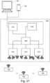
- FIG. 21 shows a schematic overview of a system in accordance with the fourth aspect of the invention for monitoring properties of or in electrical installations.
- the system comprises a gateway device 300 in accordance with the third aspect of the invention and one or more apparatus 100 in accordance with the first aspect of the invention, along with corresponding holders in accordance with the second aspect of the invention (not shown in the figure).
- the exemplary gateway device 300 shown in the figure comprises three antennas 310 that are connected to a second wireless interface 308 and that provide wireless connectivity with and electrical energy to the one or more apparatus 100.
- the antennas may provide beamforming and/or MU-MIMO-like communications, indicated by the various wireless communication symbols placed with each of the antennas.
- the exemplary gateway device 300 further comprises a data processing block 316, which may be implemented in software, hardware, or a combination thereof, and a third communication interface, which may be wired or wireless, for communicating with external data processing and/or storage apparatus, e.g., with computer 20 or mobile device 30.
- the communication with the external data processing and/or storage apparatus may be routed directly or via a further hardware or function block (not shown in the figure).
- Figure 22 shows an exemplary electrical installation 10, and a detail thereof, in which apparatus 100 in accordance with the first aspect of the invention are mounted on power bus bars.
- the exemplary electrical installation comprises a cabinet that holds various electrical devices for switching and distributing electrical energy, inter alia electrical bus bars 14.
- the detailed view shows three bus bars 14, to two of which apparatus 100 in accordance with the first aspect of the invention are mounted, e.g., by means of adhesives.
- Figure 23 shows a flow diagram of an exemplary method 500 of installing an apparatus 100 in accordance with the first aspect of the invention in an electrical installation 10.
- the apparatus 100 After providing the apparatus 100 in step 502 the apparatus 100 is positioned, in step 540, in or next to a location in the electrical installation 10, in which a property of or in the electrical installation 10 is to be monitored. Positioning may comprise providing a holder 200 in accordance with the second aspect of the invention or providing any other means of attaching or mounting the apparatus 100 in the electrical installation 10.
- electrical energy is wirelessly provided to the apparatus 100 via a gateway-device 300 of the electrical installation 10, which energy is received via a first wireless interface 106 of the apparatus 100.
- step 508 at least a field strength or a quality of the wireless connection between the apparatus 100 and the gateway-device 300 is determined in the apparatus 100 or in the gateway-device 300.
- step 510 an indication is provided, by means of an indicator provided with the apparatus 100 or the gateway-device 300, or by means of a computer 10 or mobile device 20 communicatively connected with the gateway device 300, the indication representative of the field strength or the quality of the wireless connection and/or showing that the field strength and/or the quality of the wireless connection between the apparatus 100 and the gateway-device 300 exceeds a predetermined value or level.
- the orientation and/or the location of the apparatus 100 and/or a holder 200 in the electrical installation 10 is modified, in step 512, until the field strength and/or the quality of the wireless connection between the apparatus 100 and the gateway-device 300 exceeds the predetermined value or level.
- the apparatus 100 may be fixed in that location and orientation in step 516.
- FIG. 24 shows a flow diagram of an exemplary method 600 of operating a system in accordance with the fourth aspect of the invention.
- electrical energy is wirelessly provided from a gateway-device 300 to one or more apparatus 100.
- the gateway-device 300 transmits data to the one or more apparatus 100, e.g., a polling command, configuration data or the like.
- a polling command may be required in case the apparatus 100 does not automatically transmit, upon receiving energy, whenever a communication channel is available and not busy, or when data from only one of multiple apparatus 100 is to be obtained. The latter option may be useful in case the multiple apparatus 100 do not provide a full wireless transmission protocol with congestion management.
- the gateway device receives sensor data from one or more apparatus 100, representing a sensed property of an electrical installation 10 in which the system 400 is installed.
- the gateway device evaluates the received sensor data.
- the received and/or evaluated sensor data is transmitted, in step 610, from the gateway-device 300 to a further device, e.g., a computer 20 or a mobile device 30, via a third interface 312.
Landscapes
- Engineering & Computer Science (AREA)
- Computer Networks & Wireless Communication (AREA)
- Physics & Mathematics (AREA)
- General Physics & Mathematics (AREA)
- Signal Processing (AREA)
- Arrangements For Transmission Of Measured Signals (AREA)
Priority Applications (1)
| Application Number | Priority Date | Filing Date | Title |
|---|---|---|---|
| EP23315223.0A EP4471384A1 (de) | 2023-06-01 | 2023-06-01 | Gerät zur überwachung von eigenschaften von oder in elektrischen anlagen, halter dafür und gateway-gerät für solche geräte, elektrische anlage mit solchem gerät und solchem gateway-gerät und entsprechende verfahren zur installation und betrieb |
Applications Claiming Priority (1)
| Application Number | Priority Date | Filing Date | Title |
|---|---|---|---|
| EP23315223.0A EP4471384A1 (de) | 2023-06-01 | 2023-06-01 | Gerät zur überwachung von eigenschaften von oder in elektrischen anlagen, halter dafür und gateway-gerät für solche geräte, elektrische anlage mit solchem gerät und solchem gateway-gerät und entsprechende verfahren zur installation und betrieb |
Publications (1)
| Publication Number | Publication Date |
|---|---|
| EP4471384A1 true EP4471384A1 (de) | 2024-12-04 |
Family
ID=86861872
Family Applications (1)
| Application Number | Title | Priority Date | Filing Date |
|---|---|---|---|
| EP23315223.0A Pending EP4471384A1 (de) | 2023-06-01 | 2023-06-01 | Gerät zur überwachung von eigenschaften von oder in elektrischen anlagen, halter dafür und gateway-gerät für solche geräte, elektrische anlage mit solchem gerät und solchem gateway-gerät und entsprechende verfahren zur installation und betrieb |
Country Status (1)
| Country | Link |
|---|---|
| EP (1) | EP4471384A1 (de) |
Citations (4)
| Publication number | Priority date | Publication date | Assignee | Title |
|---|---|---|---|---|
| US20030214399A1 (en) * | 2002-03-28 | 2003-11-20 | Kabushiki Kaisha Toshiba | String wireless sensor and its manufacturing method |
| US20180183622A1 (en) * | 2015-06-24 | 2018-06-28 | Lg Electronics Inc. | Electronic device, smart home system using electronic device, and method for controlling smart home system |
| US10527523B2 (en) * | 2015-12-18 | 2020-01-07 | Ge Global Sourcing Llc | Vehicle sensor assembly having an RF sensor disposed in the sensor assembly to wirelessly communicate data to outside the sensor assembly |
| DE102020207230A1 (de) * | 2020-06-09 | 2021-12-09 | Vega Grieshaber Kg | Sensorhalterung zur Befestigung eines Sensors |
-
2023
- 2023-06-01 EP EP23315223.0A patent/EP4471384A1/de active Pending
Patent Citations (4)
| Publication number | Priority date | Publication date | Assignee | Title |
|---|---|---|---|---|
| US20030214399A1 (en) * | 2002-03-28 | 2003-11-20 | Kabushiki Kaisha Toshiba | String wireless sensor and its manufacturing method |
| US20180183622A1 (en) * | 2015-06-24 | 2018-06-28 | Lg Electronics Inc. | Electronic device, smart home system using electronic device, and method for controlling smart home system |
| US10527523B2 (en) * | 2015-12-18 | 2020-01-07 | Ge Global Sourcing Llc | Vehicle sensor assembly having an RF sensor disposed in the sensor assembly to wirelessly communicate data to outside the sensor assembly |
| DE102020207230A1 (de) * | 2020-06-09 | 2021-12-09 | Vega Grieshaber Kg | Sensorhalterung zur Befestigung eines Sensors |
Non-Patent Citations (1)
| Title |
|---|
| SETIAWAN DEDI ET AL: "Experiment and Modeling of Wireless-Powered Sensor Network", 2017 IEEE WIRELESS COMMUNICATIONS AND NETWORKING CONFERENCE WORKSHOPS (WCNCW), IEEE, 19 March 2017 (2017-03-19), pages 1 - 6, XP033093188, DOI: 10.1109/WCNCW.2017.7919071 * |
Similar Documents
| Publication | Publication Date | Title |
|---|---|---|
| US20110140686A1 (en) | Thermal extension structures for monitoring bus bar terminations | |
| KR101656703B1 (ko) | 스마트 감시가 가능한 수배전반 자가진단 시스템 | |
| US8111148B2 (en) | Method and apparatus for bi-directional communication with a miniature circuit breaker | |
| JP6549550B2 (ja) | 電気システムにおける配電を監視する電力監視プローブ | |
| EP2529241B1 (de) | Detektion der qualität eines elektrischen anschlusses | |
| JP2007525672A (ja) | 通電テスト用の装置とその方法 | |
| HK1255033A1 (en) | Power monitoring probe for monitoring power distribution in an electrical system | |
| US12068587B2 (en) | Replacement panels for electrical distribution cabinets for the monitoring of targeted components and connections | |
| CN121498902A (zh) | 母线槽接头连接监视系统和其组装方法 | |
| EP4471384A1 (de) | Gerät zur überwachung von eigenschaften von oder in elektrischen anlagen, halter dafür und gateway-gerät für solche geräte, elektrische anlage mit solchem gerät und solchem gateway-gerät und entsprechende verfahren zur installation und betrieb | |
| KR101114551B1 (ko) | 비접촉 온도 감시 장치 | |
| CN213633762U (zh) | Ups测试装置 | |
| KR101510676B1 (ko) | 수배전반용 지능형 방전감시 영상시스템 | |
| KR102165951B1 (ko) | 전기 설비함의 열화방지 냉각시스템 | |
| WO2021137568A1 (ko) | 우레탄 휠용 이상 여부 감지장치 및 이를 이용한 우레탄 휠 모니터링 시스템 및 그 방법 | |
| EP3572729A1 (de) | Abschirmsystem für einen thermostaten in einem ofenhohlraum eines backofens | |
| CN217237028U (zh) | 一种机架式终端盒可拆式温度检测装置 | |
| CN115307749A (zh) | 一种具有温度监测功能的电气连接及其系统 | |
| CN106411252A (zh) | 一种交流防雷汇流配电箱 | |
| CN207150256U (zh) | 一种住宅配电设施运维自动化系统 | |
| CN207518980U (zh) | 一种电子自动化箱 | |
| CN223334948U (zh) | 一种带安全监测功能的继电器 | |
| CN223977281U (zh) | 一种高精度分流器 | |
| CN213755507U (zh) | 一种检测报警的计算机网络存储柜 | |
| CN109932073A (zh) | 一种基于rfid的断路器温度监测装置 |
Legal Events
| Date | Code | Title | Description |
|---|---|---|---|
| PUAI | Public reference made under article 153(3) epc to a published international application that has entered the european phase |
Free format text: ORIGINAL CODE: 0009012 |
|
| STAA | Information on the status of an ep patent application or granted ep patent |
Free format text: STATUS: THE APPLICATION HAS BEEN PUBLISHED |
|
| AK | Designated contracting states |
Kind code of ref document: A1 Designated state(s): AL AT BE BG CH CY CZ DE DK EE ES FI FR GB GR HR HU IE IS IT LI LT LU LV MC ME MK MT NL NO PL PT RO RS SE SI SK SM TR |
|
| STAA | Information on the status of an ep patent application or granted ep patent |
Free format text: STATUS: REQUEST FOR EXAMINATION WAS MADE |
|
| 17P | Request for examination filed |
Effective date: 20250602 |
|
| GRAP | Despatch of communication of intention to grant a patent |
Free format text: ORIGINAL CODE: EPIDOSNIGR1 |
|
| STAA | Information on the status of an ep patent application or granted ep patent |
Free format text: STATUS: GRANT OF PATENT IS INTENDED |
|
| INTG | Intention to grant announced |
Effective date: 20260129 |