EP4471222A1 - A suspended ceiling system with a folded sound scattering element - Google Patents
A suspended ceiling system with a folded sound scattering element Download PDFInfo
- Publication number
- EP4471222A1 EP4471222A1 EP23176396.2A EP23176396A EP4471222A1 EP 4471222 A1 EP4471222 A1 EP 4471222A1 EP 23176396 A EP23176396 A EP 23176396A EP 4471222 A1 EP4471222 A1 EP 4471222A1
- Authority
- EP
- European Patent Office
- Prior art keywords
- suspended ceiling
- ceiling system
- sound
- tile element
- groove
- Prior art date
- Legal status (The legal status is an assumption and is not a legal conclusion. Google has not performed a legal analysis and makes no representation as to the accuracy of the status listed.)
- Pending
Links
Images


Classifications
-
- E—FIXED CONSTRUCTIONS
- E04—BUILDING
- E04B—GENERAL BUILDING CONSTRUCTIONS; WALLS, e.g. PARTITIONS; ROOFS; FLOORS; CEILINGS; INSULATION OR OTHER PROTECTION OF BUILDINGS
- E04B9/00—Ceilings; Construction of ceilings, e.g. false ceilings; Ceiling construction with regard to insulation
- E04B9/04—Ceilings; Construction of ceilings, e.g. false ceilings; Ceiling construction with regard to insulation comprising slabs, panels, sheets or the like
- E04B9/0414—Ceilings; Construction of ceilings, e.g. false ceilings; Ceiling construction with regard to insulation comprising slabs, panels, sheets or the like being foldable, curvable or rollable
-
- E—FIXED CONSTRUCTIONS
- E04—BUILDING
- E04B—GENERAL BUILDING CONSTRUCTIONS; WALLS, e.g. PARTITIONS; ROOFS; FLOORS; CEILINGS; INSULATION OR OTHER PROTECTION OF BUILDINGS
- E04B9/00—Ceilings; Construction of ceilings, e.g. false ceilings; Ceiling construction with regard to insulation
- E04B9/001—Ceilings; Construction of ceilings, e.g. false ceilings; Ceiling construction with regard to insulation characterised by provisions for heat or sound insulation
Definitions
- the present invention relates to a suspended ceiling system comprising a grid of profiles and a plurality of tile elements being supported by flanges of the profiles.
- the plurality of tile elements comprising at least one folded sound scattering tile element.
- Suspended ceiling systems comprising sound altering or sound absorbing tiles are found in many rooms. Usually, these systems are designed to uniformly absorb sound so that the sound level everywhere in the room is kept down. However, in some rooms other characteristics may be wanted and sound to be scattered or reflected from certain positions to other positions. This, for example, could be the case in a room designed for lectures. Here sound from the audience could be wanted to be absorbed but sound from the lecturer could be wanted to be at least partly reflected towards the audience.
- Patent document EP 2 662 504 A1 discloses reflective ceiling tiles for a nonplanar suspended ceiling of a room.
- the ceiling tiles are installable in a profile assembly where the ceiling tiles in an installed state are inclined. By this inclination, a sound scattering effect may be achieved.
- the inclination of a tile depends on the thickness of the tile in relation to the width of it.
- width of a tile is meant the distance of the tile between the sides which are supported by a supporting structure, for example profiles.
- a thicker ceiling tile with a reduced width may allow for a slight increase in inclination and thus improved sound scattering effect, but would be heavier and more difficult to install.
- patent document EP 3 901 386 A1 discloses an acoustic system for improving acoustic quality in a room for speech.
- the system has ceiling tiles where a first group of ceiling tiles has sound absorbing properties and a second group of ceiling tiles has sound diffusing properties.
- a suspended ceiling system comprising a plurality of tiles and a grid of profiles.
- the grid of profiles comprises profiles provided with support flanges arranged in a common horizontal plane and supporting the plurality of tiles.
- the plurality of tiles comprises at least one sound scattering tile element having a body and a surface layer.
- the body is made of sound absorptive material and has a front surface and an opposing rear surface.
- the sound absorptive material has a sound absorption coefficient of at least 0,3.
- the surface layer has sound reflecting properties and is arranged on the front surface of the body.
- the body is provided with a groove in the rear surface of the body such that the at least one sound scattering tile element is foldable with the surface layer acting as a joint about an axis extending in parallel with the groove.
- the at least one sound scattering tile element supported by the profiles of the grid of profiles is folded.
- the tile element By being folded the tile element can achieve an inclination of at least a portion of the surface layer with respect to the common horizontal plane.
- the tile element has sound scattering properties in its folded and installed state, and may also direct sound in certain directions, for example away from the position of a speaker towards the position of an intended audience.
- the tile element may easily be installed in the grid of profiles since the size of the tile element, at least in one extension, can be reduced by folding it. By having its size reduced, the tile element may more easily be brought into the grid and then positioned such that it is supported by the flanges.
- the groove allows the tile element to be made cheaply as the tile element may be made from a standard ceiling tile.
- the body of the tile element may be provided with the groove by a milling or cutting operation.
- the at least one sound scattering tile element may be folded such that the axis is arranged below the common horizontal plane. By being arranged in this manner, an improved sound scattering effect may be achieved.
- the tile element may protrude downwards, out from the grid of profiles. Sound waves may thus reach the tile element and be directly reflected away.
- the surface layer may have an air flow resistance of at least 70 000 Pas/m. Such a resistance makes sure that sound waves will be reflected from the surface layer in a desired manner.
- the groove may have a cross-sectional shape of a V.
- This is a shape that allows for easy and controlled folding and may give a suitable shape for a folded tile element.
- Such a shape of a folded tile element allows for at least a portion of the tile element to be inclined with respect to the horizontal plane and the tile may thus scatter impinging sound waves and also direct sound in a certain direction. Such a shape makes it so that the folded tile element may be folded without leaving any empty spaces in the fold.
- the at least one sound scattering tile element may be folded such that groove surfaces defining the groove abut each other. This may increase the mechanical strength of the tile element and ensure that the tile element may maintain its folded state over time.
- the at least one sound scattering tile element may be folded such that opposing groove surfaces abut each other. This may increase the mechanical strength of the tile element and ensure that the tile element maintains its folded state over time. This at least because opposing groove surfaces themselves press against each other and thus affect each other in equal manners, providing stability.
- a front side of the surface layer may be covered by a paint or coating.
- a paint By application of a paint, the acoustic properties of the surface layer may be altered.
- the paint may increase the air flow resistance which in turn may increase the reflection of sound waves.
- the paint may be looked at as being part of the surface layer or comprised by the surface layer.
- the body may comprise opposing lateral engagement surfaces each extending in a plane parallel to the horizontal plane and resting on a respective support flange of the support flanges of the profiles. This allows the at least one sound scattering tile element to rest securely on the support flanges such that the tile element is kept in the folded state.
- the at least one sound scattering tile element may comprise an elongated reinforcing structure extending along the joint. This may improve the strength of the folded tile element and keep it in its folded state.
- the elongated reinforcing structure may comprise a pair of protruding members each extending from the elongated reinforcing structure into the body of the at least one sound scattering tile element such that the at least one sound scattering tile element is fixed in its folded state. This may improve the strength of the tile element and keep it in its folded state.
- the at least one sound scattering tile element may be fixated in a folded state by means of an adhesive.
- An adhesive may fixate the tile element in the folded state.
- An adhesive may be applied in a simple manner to the groove and does not necessarily need any complicated design of the groove surfaces.
- the adhesive may for example be in the form of a glue, of a paste or of a tape.
- the body may have a uniform thickness. This will be easier and cheaper to manufacture and can provide similar acoustic properties to the tile element.
- the body may be in the form of a parallelepiped in a non-folded state of the at least one sound scattering tile element. This is a form which is easy and cheap to manufacture and easy to fold after a groove has been created in it.
- the body may comprise a first portion at a first side of the groove and a second portion at a second side of the groove, wherein the first side and the second side are on mutual opposite sides of the groove.
- a first section of the surface layer associated with the first portion may have a first air flow resistance and a second section of the surface layer associated with the second portion may have a second air flow resistance.
- the first air flow resistance and the second air flow resistance may be different. This may allow the tile element to scatter sound or direct sound waves differently in different directions. It may also allow the tile element to absorb sound waves differently depending on angle of incidence.
- the first air flow resistance and the second air flow resistance may be different by at least a factor of 2.
- the first air flow resistance may be at least 90 000 Pas/m and the second air flow resistance may be at most 50 000 Pas/m.
- the first portion may have a first inclination with respect to the common horizontal plane and the second portion may have a second inclination with respect to the common horizontal plane.
- the first inclination may be at least 20 degrees.
- the first inclination and the second inclination may be different by at a least 10 degrees, or by at least a factor of 2, or by both at least 10 degrees and at least a factor of 2.
- FIG. 1 shows a ceiling system 1 from below in a perspective view.
- the ceiling system 1 is intended to be installed in a room with the ceiling system 1 having a front side facing downwards, towards the room, and a rear side facing upwards, away from the room and towards a structural ceiling.
- the ceiling system 1 is intended to be suspended from the structural ceiling and comprises profiles 21 forming a grid of profiles 20 and a plurality of tiles.
- the plurality of tiles comprises at least one sound scattering tile element 10. In the shown embodiments, all tiles are in the form of sound scattering tile elements 10.
- the tile elements 10 are supported by the grid of profiles 20.
- the profiles 21 themselves are attached to the structural ceiling, for example by being suspended by wires or rods attached to the structural ceiling. Since the grid of profiles 20 is suspended there is a space or plenum between the grid of profiles 20 and the structural ceiling, and therefore also between the ceiling system 1 and the structural ceiling.
- the grid of profiles 20 is arranged to form rectangular frames in which the tile elements 10 are arranged. Rectangular frames are suitable shapes for ceiling systems where tile elements are supported on profiles, but other shapes are possible as well.
- the tile elements 10 each fits into a respective frame and is in contact with the profiles which form the frame. Thus, each tile element 10 is horizontally secured in each frame and does not move about in horizontal directions.
- the rightmost tile element 10 in Figure 1 is for reasons of clarity shown with a portion cut off. This is to show how the tile elements 10 are supported by the grid of profiles 20 and how the grid of profiles 20 are designed. This does not mean that the portion of the rightmost tile element 10 is actually cut off, rather it is identical to the other tile elements 10 of Figure 1 .
- the profiles 21 are provided with support flanges 23.
- Each profile 21 having a web or a vertical portion 22 and a support flange 23 connected to and extending from a lower end of the vertical portion 22 on both sides thereof.
- the free, upper end of the vertical portion may be provided with a reinforcing bulb (not shown). It is the vertical portion which is intended to be connected to the structural ceiling via wires or rods.
- the vertical portion 22 and the support flange 23 each extend along the entire length of the profile 21. It is on the support flanges 23 which the tile elements 10 are supported. This is also more clearly shown in later figures.
- Each tile element 10 is supported by two profiles 21, which profiles 21 extend in parallel to each other.
- the support flanges 23 are arranged in a common horizontal plane. Thus the tile elements 10 are supported on and arranged on a common horizontal plane as well.
- the tile elements 10 are folded and protrude downwards from the grid of profiles 20.
- the sound scattering tile elements 10 will be described in more detail in later figures.
- the sound scattering tile elements 10 each comprises a body 11 and a surface layer 12.
- the body 11 is made of sound absorptive material and has a front surface and an opposing rear surface.
- the front surface is intended to face the room below the suspended ceiling system.
- the surface layer 12 has sound reflecting properties and is arranged on the front surface of the body 11.
- the surface layer 12 may have an air flow resistance of at least 50 000 Pas/m, preferably of at least 70 000 Pas/m, or of at least 90 000 Pas/m.
- the surface layer 12 may be provided with a coating, such as a paint, in which case the air flow resistance of the surface layer may be dependent on the applied amount and type of coating.
- the air flow resistance of the surface layer is of course also dependent of the type and structure of the surface layer.
- the tile elements 10 have sound scattering properties at least because they have any one of the following properties: they protrude from the grid of profiles 20; they have front surfaces which are inclined relative to the common horizontal plane; they have a surface layer with sound reflecting properties. These properties may be configured to give a tile element specific wanted sound scattering properties.
- the suspended ceiling system 1 may comprise other tiles.
- both folded and non-folded tiles and both protruding and non-protruding tiles are feasible.
- the sound scattering properties of the ceiling system 1 may thus be designed by choosing tiles with desired sound absorbing and sound scattering properties and placing these tiles at desired positions. Thus sound coming from inside a room may be scattered away from certain positions and/or towards certain directions and/or absorbed at certain positions.
- a sound scattering tile element 10 is shown in perspective views from above.
- the sound scattering tile element 10 is shown in an unfolded state and in Figure 2B the sound scattering tile element 10 is shown in a folded state and supported by profiles 21.
- the sound scattering tile element 10 and the profiles 21 are suitable for forming a or at least a part of a suspended ceiling system 1, such as the one shown in Figure 1 .
- the tile element 10 has a body 11 which in the unfolded state has a rectangular panel shape with a uniform thickness.
- the uniform thickness is before taking into account any grooves or cuts made into the body 11.
- a surface layer 12 is arranged on a front surface of the body 11, the front surface being the surface of the body 11 intended to face the room in the installed state of the suspended ceiling system 1.
- the rear surface of the body 11 is provided with a groove 13, the rear surface being the surface of the body 11 which is intended to face upwards, away from the room and towards a structural ceiling in the installed state of the suspended ceiling system 1.
- the groove 13 extends along the length of the body 11. In the shown embodiment, the groove 13 extends in parallel with two opposing side edges of the body 11 and orthogonally with regards to the two other opposing sides edges of the body 11. The groove 13 does not fully extend through the tile element 10 but at least leaves the surface layer 12 and the front side of the tile element 10 intact.
- the groove 13 has a cross section in the shape of a V.
- the groove 13 has a triangular shape.
- Each side of the groove 13 has the same length between the front side of the body 11 and the rear side of the body 11. Length here being the distance along the groove between the front side of the body 11 and the rear side of the body 11.
- Each side of the groove 13 has the same angle between the respective side and the front side of the body 11.
- Other cross sectional shapes are possible but the shape of a V is a shape which is suitable for folding a tile element 10 about an axis and which shape can provide a suitable shape of the tile element 10 in the folded state.
- the groove 13 is configured to form a channel in the folded state of the tile element 10.
- the channel is defined by sub grooves 15 formed in the sides or surfaces of the groove 13 and is configured for reception of an elongated reinforcing structure 16.
- the elongated reinforcing 16 structure could for example be a rod made of metal such as aluminum or steel.
- the channel extends along the groove 13. As illustrated, the channel may extend along the entire length of groove 13 and the body 11. However, the channel only needs to be as long as the reinforcing structure 16 itself.
- the tile element 10 comprises opposing lateral engagement surfaces 14.
- Each engagement surface 14 is formed by a surface section of a cut out provided in the front side at a respective side edge portion of the tile element 10. Although not visible in Figure 2A as such, these engagement surfaces 14 extend along the entire length of the body 11. This is more visible in Figure 4 .
- the opposing lateral engagement surfaces 14 are formed such that they extend in a plane parallel to the common horizontal plane of the profiles 21 when the tile element 10 is folded and supported by the profiles 21. As can be seen in later figures, it is these opposing lateral engagement surfaces 14 which rest on a respective support flange 23 such that the tile element 10 is supported by the profiles 21.
- opposite lateral engagement surfaces 14 should here be understood as that the engagement surfaces 14 are arranged in a respective side edge portion of the tile element 10 on opposing sides of the groove 13.
- the groove 13 extends in parallel with the lateral engagement surfaces 14 and will thus, in a folded state of the tile element 10, extend in parallel with the profiles 21 which support the tile element 10 in the ceiling system 1.
- the tile element 10 is in a folded state and is supported by profiles 21.
- the profiles 21 each has a vertical portion 22 and a support flange 23 attached to the lower end of the vertical portion 22.
- the folded tile element 10 has a shape of a V where each engagement surface 14 of the cut outs abuts a respective support flange 23 of a profile 21.
- the tile element 10 is folded along the groove 13 with the surface layer 12 acting as a joint about an axis extending in parallel with the groove 13.
- the tile element is folded by bringing the surfaces defining the grooves towards each other.
- surfaces defining the groove is here meant the surfaces which define the groove without taking into account any cuts made into the groove, for example the sub grooves 15 made for forming the channel configured for reception of the reinforcement structure.
- the tile element 10 is folded such that the tile element 10 protrudes downwards from the common horizontal plane with the axis being arranged below the common horizontal plane.
- the front surface of the tile element 10 is arranged below the common horizontal plane and may facilitate scattering of sound in the room.
- Elongated reinforcing structures 16 are shown which may be inserted into the channel formed by the sub grooves 15 of the groove 13.
- the channel does only have to be as long as the elongated reinforcing structure 16.
- two elongated reinforcing structures 16 are shown in Figure 2B , there would in such case be two channels, one at each end of the groove 13.
- the reinforcement structure 16 may be arranged in the groove prior to or after folding of the tile element 10.
- the elongated reinforcing structure 16 comprises a pair of protruding members 17, here in the form of flanges or wings.
- the reinforcing structure 16 could alternatively also be in the form of rods.
- the reinforcement structure 16 When comprising a pair of protruding members 17, the reinforcement structure 16 may be inserted into the channel after folding of the tile element 10.
- the protruding members 17 will when inserted into the channel extend into the body 11 of the tile element 10 such that the tile element 10 is fixed in the folded state.
- the channel may be provided with slits or slots configured for reception of the pair of protruding members 17.
- FIG 3 another sound scattering tile element 10 is shown in a perspective view from above.
- the tile element 10 is in a folded state and is supported by profiles 21.
- the sound scattering tile element 10 and the profiles 21 of Figure 3 are suitable for forming a or at least a part of a suspended ceiling system 1, such as the one shown in Figure 1 .
- the tile element 10 in Figure 3 is similar to the tile elements 10 shown in other figures, but here the tile element 10 is provided with two grooves 13 instead of just one.
- Each groove 13 may be of the same type as the groove 13 of the tile element 10 of Figures 2A and 2B , such as being V-shaped and having sub grooves 15 for forming a channel for reception of an elongated reinforcing structure 16.
- the V-shapes are not necessarily identical to the V-shapes of the grooves 13 of the other figures. Different V-shapes allows for different inclinations of the folds.
- inclination of a fold is meant the inclination of one of the portions 11a, 11b, 11c of the body directly on one side of a fold with respect to one of the portions 11a, 11b, 11c of the body directly on the opposite side of the fold.
- the tile elements 10 of the other figures have one fold along the one groove 13 with a first portion 11a of the body on a first side of the groove 13 and a second portion 11b of the body on a second, opposite, side of the groove 13, this tile element 10 has two folds, each along a respective groove 13, and three portions 11a, 11b, 11c of the body.
- the portions 11a, 11b, 11c are separated by grooves 13, with a first groove 13 being formed between the first portion 11a and the central portion 11c and a second groove 13 being formed between the second portion 11b and the central portion 11c.
- the first side portion 11a is arranged on a first side of the tile element 10 and abuts a first profile 21.
- the second portion 11b is arranged on a second, opposite, side of the tile element 10 and abuts a second profile 21.
- the central portion 11c is arranged between the first portion 11a and the second portion 11b.
- the central portion 11c extends in parallel to the common horizontal plane.
- the first side portion 11a and the second side portion 11b extend in respective planes which are inclined to the common horizontal plane
- a sound scattering tile element 10 is shown in a perspective view from below.
- the tile element 10 is in a folded state and is lowered down towards profiles 21.
- the sound scattering tile element 10 and the profiles 21 of Figure 4 are suitable for forming a or at least a part of a suspended ceiling system 1, such as the one shown in Figure 1 .
- the tile element 10 in Figure 4 is similar to the tile elements 10 shown in other figures, but here the tile element 10 is folded asymmetrically.
- the groove 13 of the tile element 10 may be of the same type as the grooves 13 of the tile elements 10 of the other figures, for example being V-shaped and having sub grooves 15 for forming a at least one channel for reception of one or more elongated reinforcing structures 16.
- the V-shape is not necessarily identical to the V-shapes of the grooves 13 of the other figures and thus other inclinations of the folds are possible.
- the tile element 10 is folded asymmetrically.
- the groove 13 is not symmetrically arranged and does thus not form two identical portions 11a, 11b on opposing sides of the groove 13. Consequently, the tile element 10 is folded such that the first portion 11a of the body is not of the same width as the second portion 11b of the body.
- width is in this context meant the distance between the fold and the respective side edge of the body 11.
- first portion 11a of the body is smaller than the width of the second portion 11b of the body.
- the first portion 11a extends along a plane having an inclination which, with respect to the horizontal plane, is different from the inclination, with respect to the horizontal plane, of the plane which the second portion 11b extends along.
- the sound scattering tile elements 10 they all have a body 11 having a front surface and an opposite rear surface.
- the front surface faces downwards towards a room and the rear surface faces upwards, towards the structural ceiling of a room.
- the body 11 is made of a sound absorptive materials, such as mineral wool.
- the sound absorptive material has a sound absorption coefficient of at least 0,3.
- Other possible values for the sound absorption coefficient is at least 0,5 or at least 0,7 or even at least 0,9.
- the tile elements 10 each have a surface layer 12 which is arranged on the front surface of the body 11.
- the surface layer 12 has sound reflecting properties. This may at least partly be achieved by having the front side of the surface layer 12 covered by a paint which has sound reflecting properties. The paint may adjust the air flow resistance of the surface layer.
- the tile elements 10 may be folded in different ways.
- the tile elements 10 may be folded along one fold or along several folds.
- the tile elements 10 may be folded in a symmetrical way or in an asymmetrical way.
- the portion of the body 11 on one side of the fold may be wider than the portion of the body 11 on the opposing side of the fold, wider here referring to the distance between the fold and the respective side edge of the body 11.
- the body may comprise a first portion 11a at a first side of the groove 13 and a second portion 11b at a second side of the groove 13, the first side and the second side being on opposite sides of the groove 13.
- the first portion 11a and the second portion 11b each has a respective front surface and a respective surface layer 12.
- a first section, associated with the surface layer of the first portion 11a, may have a first air flow resistance.
- a second section, associated with the surface layer of the second portion 11b, may have a second air flow resistance.
- the first air flow resistance and the second air flow resistance may be different. Alternatively, they may be equal.
- the air flow resistances may be configured to provide a desired sound scattering effect of the sound scattering tile elements 10.
- the air flow resistance may for example, as mentioned earlier, be configured by choosing a specific type and/or amount of paint which may be applied to the surface layer 12.
- the air flow resistance of the surface layer is of course also dependent of the type and structure of the surface layer.
- the first air flow resistance of the surface layer 12 may be between 70 000 Pas/m and 140 000 Pas/m, preferably between 90 000 Pas/m and 140 000 Pas/m, more preferably between 90 000 Pas/m and 120 000 Pas/m.
- the first air flow resistance should preferably be at least 90 000 Pas/m.
- the second air flow resistance is between 0 Pas/m and 70 000 Pas/m, preferably between 10 000 Pas/m and 50 000 Pas/m, more preferably between 20 000 Pas/m and 40 000 Pas/m.
- the second air flow resistance should preferably be at most 70 000 Pas/m, more preferably at most 50 000 Pas/m.
- the first air flow resistance and the second air flow resistance are preferably different by at least a factor of 2.
- the first portion 11a has a first inclination with respect to the common horizontal plane.
- the second portion 11b has a second inclination with respect to the common horizontal plane.
- the first inclination and the second inclination can be different.
- the inclination may be equal.
- the inclination of the first portion 11a and the second portion 11b is between 40 and 50 degrees, and the inclination of the central portion 11c is between 0 and 10 degrees.
- the first inclination and the second inclination are both between 40 and 50 degrees.
- the first inclination is between 55 and 65 degrees and the second inclination is between 25 and 35 degrees.
- the first inclination should preferably be at least 20 degrees.
- first inclination and the second inclination may be different by at least 10 degrees.
- the first inclination and the second inclination may be different by at least a factor of 2.
- the first inclination and the second inclination may be different by both at least 10 degrees and at least a factor of 2.
- Inclinations of the portions 11a, 11b, 11c as illustrated inf Figure 3 may be adjusted by for example adjusting the cross sectional shape of the grooves 13 which in its turn will give differently inclined folds. Another example is to adjust the inclination of the lateral engagement surfaces 14 with regard to the front surface.
- the first air flow resistance is associated with the first portion 11a and the second portion air flow resistance with the second portion 11b
- the values of the air flow resistances can apply for sections associated with a the first portion 11a, the second portion 11b or the central portion 11c. This also applies for the values of the inclinations of the first portion 11a and the second portion 11b which can apply for the first portion 11a, the second portion 11b or the central portion 11c.
- the sound scattering tile elements 10 are folded in such a manner that groove surfaces defining groove abut each other. Not only that but they are folded such that opposing groove surfaces abut each other.
- the folds are fixed by elongated reinforcing structures.
- Another way of fixing the tile elements 10 in the folded state is by means of an adhesive, such as a glue or an adhesive tape.
- the glue may be applied in the groove 13 prior to folding.
- the glue may be applied on opposing groove surfaces, that is surfaces opposing each other when the tile element 10 is folded.
- the adhesive tape may be applied on the rear side of the tile element 10 after the tile element 10 has been folded. If the adhesive tape has adhesive properties on both sides of the adhesive tape, the adhesive tape may be applied in the groove 13 prior to folding, for example such that the adhesive tape is placed between opposing groove surfaces when the tile element 10 is folded.
Landscapes
- Engineering & Computer Science (AREA)
- Architecture (AREA)
- Physics & Mathematics (AREA)
- Electromagnetism (AREA)
- Civil Engineering (AREA)
- Structural Engineering (AREA)
- Building Environments (AREA)
Abstract
Description
- The present invention relates to a suspended ceiling system comprising a grid of profiles and a plurality of tile elements being supported by flanges of the profiles. The plurality of tile elements comprising at least one folded sound scattering tile element.
- Suspended ceiling systems comprising sound altering or sound absorbing tiles are found in many rooms. Mostly, these systems are designed to uniformly absorb sound so that the sound level everywhere in the room is kept down. However, in some rooms other characteristics may be wanted and sound to be scattered or reflected from certain positions to other positions. This, for example, could be the case in a room designed for lectures. Here sound from the audience could be wanted to be absorbed but sound from the lecturer could be wanted to be at least partly reflected towards the audience.
- Patent document
EP 2 662 504 A1 discloses reflective ceiling tiles for a nonplanar suspended ceiling of a room. The ceiling tiles are installable in a profile assembly where the ceiling tiles in an installed state are inclined. By this inclination, a sound scattering effect may be achieved. - However, with these ceiling tiles it is not feasible to achieve more than a limited sound scattering effect due to the limited inclination of the ceiling tiles.
- In this document the inclination of a tile depends on the thickness of the tile in relation to the width of it. By width of a tile is meant the distance of the tile between the sides which are supported by a supporting structure, for example profiles. A thicker ceiling tile with a reduced width may allow for a slight increase in inclination and thus improved sound scattering effect, but would be heavier and more difficult to install.
- In order to be able to better direct sound waves, a solution as presented in patent document
EP 3 901 386 A1 can be used. This document discloses an acoustic system for improving acoustic quality in a room for speech. The system has ceiling tiles where a first group of ceiling tiles has sound absorbing properties and a second group of ceiling tiles has sound diffusing properties. - In view of the above it is an object of the present invention to provide a suspended ceiling system which can scatter and absorb sound waves while being cheap and easy to install.
- To achieve these objects and also other objects that will be evident from the following description, a suspended ceiling system having the features defined in
claim 1 is provided according to the present disclosure. Preferred embodiments of the system will be evident from the dependent claims. - More specifically there is provided a suspended ceiling system comprising a plurality of tiles and a grid of profiles. The grid of profiles comprises profiles provided with support flanges arranged in a common horizontal plane and supporting the plurality of tiles. The plurality of tiles comprises at least one sound scattering tile element having a body and a surface layer. The body is made of sound absorptive material and has a front surface and an opposing rear surface. The sound absorptive material has a sound absorption coefficient of at least 0,3. The surface layer has sound reflecting properties and is arranged on the front surface of the body. The body is provided with a groove in the rear surface of the body such that the at least one sound scattering tile element is foldable with the surface layer acting as a joint about an axis extending in parallel with the groove. The at least one sound scattering tile element supported by the profiles of the grid of profiles is folded.
- By being folded the tile element can achieve an inclination of at least a portion of the surface layer with respect to the common horizontal plane. Thus the tile element has sound scattering properties in its folded and installed state, and may also direct sound in certain directions, for example away from the position of a speaker towards the position of an intended audience.
- Further, by being folded the tile element may easily be installed in the grid of profiles since the size of the tile element, at least in one extension, can be reduced by folding it. By having its size reduced, the tile element may more easily be brought into the grid and then positioned such that it is supported by the flanges.
- The groove allows the tile element to be made cheaply as the tile element may be made from a standard ceiling tile. For instance, the body of the tile element may be provided with the groove by a milling or cutting operation.
- The at least one sound scattering tile element may be folded such that the axis is arranged below the common horizontal plane. By being arranged in this manner, an improved sound scattering effect may be achieved. The tile element may protrude downwards, out from the grid of profiles. Sound waves may thus reach the tile element and be directly reflected away.
- The surface layer may have an air flow resistance of at least 70 000 Pas/m. Such a resistance makes sure that sound waves will be reflected from the surface layer in a desired manner.
- The groove may have a cross-sectional shape of a V. This is a shape that allows for easy and controlled folding and may give a suitable shape for a folded tile element. Such a shape of a folded tile element allows for at least a portion of the tile element to be inclined with respect to the horizontal plane and the tile may thus scatter impinging sound waves and also direct sound in a certain direction. Such a shape makes it so that the folded tile element may be folded without leaving any empty spaces in the fold.
- The at least one sound scattering tile element may be folded such that groove surfaces defining the groove abut each other. This may increase the mechanical strength of the tile element and ensure that the tile element may maintain its folded state over time.
- The at least one sound scattering tile element may be folded such that opposing groove surfaces abut each other. This may increase the mechanical strength of the tile element and ensure that the tile element maintains its folded state over time. This at least because opposing groove surfaces themselves press against each other and thus affect each other in equal manners, providing stability.
- A front side of the surface layer may be covered by a paint or coating. By application of a paint, the acoustic properties of the surface layer may be altered. For example, the paint may increase the air flow resistance which in turn may increase the reflection of sound waves. The paint may be looked at as being part of the surface layer or comprised by the surface layer.
- The body may comprise opposing lateral engagement surfaces each extending in a plane parallel to the horizontal plane and resting on a respective support flange of the support flanges of the profiles. This allows the at least one sound scattering tile element to rest securely on the support flanges such that the tile element is kept in the folded state.
- The at least one sound scattering tile element may comprise an elongated reinforcing structure extending along the joint. This may improve the strength of the folded tile element and keep it in its folded state.
- The elongated reinforcing structure may comprise a pair of protruding members each extending from the elongated reinforcing structure into the body of the at least one sound scattering tile element such that the at least one sound scattering tile element is fixed in its folded state. This may improve the strength of the tile element and keep it in its folded state.
- The at least one sound scattering tile element may be fixated in a folded state by means of an adhesive. An adhesive may fixate the tile element in the folded state. An adhesive may be applied in a simple manner to the groove and does not necessarily need any complicated design of the groove surfaces. The adhesive may for example be in the form of a glue, of a paste or of a tape.
- The body may have a uniform thickness. This will be easier and cheaper to manufacture and can provide similar acoustic properties to the tile element.
- The body may be in the form of a parallelepiped in a non-folded state of the at least one sound scattering tile element. This is a form which is easy and cheap to manufacture and easy to fold after a groove has been created in it.
- The body may comprise a first portion at a first side of the groove and a second portion at a second side of the groove, wherein the first side and the second side are on mutual opposite sides of the groove. A first section of the surface layer associated with the first portion may have a first air flow resistance and a second section of the surface layer associated with the second portion may have a second air flow resistance. The first air flow resistance and the second air flow resistance may be different. This may allow the tile element to scatter sound or direct sound waves differently in different directions. It may also allow the tile element to absorb sound waves differently depending on angle of incidence.
- The first air flow resistance and the second air flow resistance may be different by at least a factor of 2. The first air flow resistance may be at least 90 000 Pas/m and the second air flow resistance may be at most 50 000 Pas/m.
- The first portion may have a first inclination with respect to the common horizontal plane and the second portion may have a second inclination with respect to the common horizontal plane. The first inclination may be at least 20 degrees.
- The first inclination and the second inclination may be different by at a least 10 degrees, or by at least a factor of 2, or by both at least 10 degrees and at least a factor of 2.
- Generally, the terms of the used in the claims are to be interpreted as they usually are in the technical field. Unless they are explicitly defined differently in this application.
- All references to "a/an/the [element, device, component, means, step, etc]" are to be interpreted openly as referring to at least one instance of said element, device, component, means, step, etc., unless explicitly stated otherwise. The steps of any method disclosed herein do not have to be performed in the exact order disclosed, unless explicitly stated.
- The above, as well as additional objects, features and advantages of the present invention, will be better understood through the following illustrative and non-limiting detailed description of preferred embodiments of the present invention, with reference to the appended drawings, where the same reference numerals will be used for similar elements, wherein:
-
Fig. 1 shows a perspective view from below of a suspended ceiling system. -
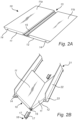
Fig. 2A shows a perspective view from above of a sound scattering tile element in an unfolded state. -
Fig. 2B shows a perspective view from above of the sound scattering tile element ofFig. 2A in a folded state and supported by profiles. -
Fig. 3 shows a perspective view from above of a sound scattering tile element in a folded state and supported by profiles. -
Fig. 4 shows a perspective view from below of a sound scattering tile element in a folded state and lowered down towards profiles. - The present invention will now be described more fully hereinafter with reference to the accompanying drawings, in which currently preferred embodiments of the invention are shown. This invention may, however, be embodied in many different forms and should not be construed as limited to the embodiments set forth herein; rather these embodiments are provided for thoroughness and completeness, and fully convey the scope of the invention to the skilled person.
-
Figure 1 shows aceiling system 1 from below in a perspective view. Theceiling system 1 is intended to be installed in a room with theceiling system 1 having a front side facing downwards, towards the room, and a rear side facing upwards, away from the room and towards a structural ceiling. Theceiling system 1 is intended to be suspended from the structural ceiling and comprisesprofiles 21 forming a grid ofprofiles 20 and a plurality of tiles. The plurality of tiles comprises at least one sound scatteringtile element 10. In the shown embodiments, all tiles are in the form of sound scatteringtile elements 10. Thetile elements 10 are supported by the grid ofprofiles 20. Theprofiles 21 themselves are attached to the structural ceiling, for example by being suspended by wires or rods attached to the structural ceiling. Since the grid ofprofiles 20 is suspended there is a space or plenum between the grid ofprofiles 20 and the structural ceiling, and therefore also between theceiling system 1 and the structural ceiling. - In
Figure 1 , the grid ofprofiles 20 is arranged to form rectangular frames in which thetile elements 10 are arranged. Rectangular frames are suitable shapes for ceiling systems where tile elements are supported on profiles, but other shapes are possible as well. - The
tile elements 10 each fits into a respective frame and is in contact with the profiles which form the frame. Thus, eachtile element 10 is horizontally secured in each frame and does not move about in horizontal directions. Therightmost tile element 10 inFigure 1 is for reasons of clarity shown with a portion cut off. This is to show how thetile elements 10 are supported by the grid ofprofiles 20 and how the grid ofprofiles 20 are designed. This does not mean that the portion of therightmost tile element 10 is actually cut off, rather it is identical to theother tile elements 10 ofFigure 1 . - As is more clearly shown in later figures, the
profiles 21 are provided withsupport flanges 23. Eachprofile 21 having a web or avertical portion 22 and asupport flange 23 connected to and extending from a lower end of thevertical portion 22 on both sides thereof. The free, upper end of the vertical portion may be provided with a reinforcing bulb (not shown). It is the vertical portion which is intended to be connected to the structural ceiling via wires or rods. Thevertical portion 22 and thesupport flange 23 each extend along the entire length of theprofile 21. It is on thesupport flanges 23 which thetile elements 10 are supported. This is also more clearly shown in later figures. Eachtile element 10 is supported by twoprofiles 21, which profiles 21 extend in parallel to each other. The support flanges 23 are arranged in a common horizontal plane. Thus thetile elements 10 are supported on and arranged on a common horizontal plane as well. - As can be seen in
Figure 1 , thetile elements 10 are folded and protrude downwards from the grid ofprofiles 20. The sound scatteringtile elements 10 will be described in more detail in later figures. - The sound scattering
tile elements 10 each comprises abody 11 and asurface layer 12. - The
body 11 is made of sound absorptive material and has a front surface and an opposing rear surface. The front surface is intended to face the room below the suspended ceiling system. - The
surface layer 12 has sound reflecting properties and is arranged on the front surface of thebody 11. Thesurface layer 12 may have an air flow resistance of at least 50 000 Pas/m, preferably of at least 70 000 Pas/m, or of at least 90 000 Pas/m. Thesurface layer 12 may be provided with a coating, such as a paint, in which case the air flow resistance of the surface layer may be dependent on the applied amount and type of coating. The air flow resistance of the surface layer is of course also dependent of the type and structure of the surface layer. - The
tile elements 10 have sound scattering properties at least because they have any one of the following properties: they protrude from the grid ofprofiles 20; they have front surfaces which are inclined relative to the common horizontal plane; they have a surface layer with sound reflecting properties. These properties may be configured to give a tile element specific wanted sound scattering properties. - Although in
Figure 1 every tile is a sound scatteringtile element 10 which is folded and protrudes downwards, this does not have to be the case. In addition to a folded, downwards protruding tile element the suspendedceiling system 1 may comprise other tiles. For example, both folded and non-folded tiles and both protruding and non-protruding tiles are feasible. The sound scattering properties of theceiling system 1 may thus be designed by choosing tiles with desired sound absorbing and sound scattering properties and placing these tiles at desired positions. Thus sound coming from inside a room may be scattered away from certain positions and/or towards certain directions and/or absorbed at certain positions. - In
Figure 2A and 2B , a sound scatteringtile element 10 is shown in perspective views from above. InFigure 2A the sound scatteringtile element 10 is shown in an unfolded state and inFigure 2B the sound scatteringtile element 10 is shown in a folded state and supported byprofiles 21. The sound scatteringtile element 10 and theprofiles 21 are suitable for forming a or at least a part of a suspendedceiling system 1, such as the one shown inFigure 1 . - The
tile element 10 has abody 11 which in the unfolded state has a rectangular panel shape with a uniform thickness. The uniform thickness is before taking into account any grooves or cuts made into thebody 11. Asurface layer 12 is arranged on a front surface of thebody 11, the front surface being the surface of thebody 11 intended to face the room in the installed state of the suspendedceiling system 1. - The rear surface of the
body 11 is provided with agroove 13, the rear surface being the surface of thebody 11 which is intended to face upwards, away from the room and towards a structural ceiling in the installed state of the suspendedceiling system 1. Thegroove 13 extends along the length of thebody 11. In the shown embodiment, thegroove 13 extends in parallel with two opposing side edges of thebody 11 and orthogonally with regards to the two other opposing sides edges of thebody 11. Thegroove 13 does not fully extend through thetile element 10 but at least leaves thesurface layer 12 and the front side of thetile element 10 intact. - In the shown embodiment, the
groove 13 has a cross section in the shape of a V. In other words, thegroove 13 has a triangular shape. Each side of thegroove 13 has the same length between the front side of thebody 11 and the rear side of thebody 11. Length here being the distance along the groove between the front side of thebody 11 and the rear side of thebody 11. Each side of thegroove 13 has the same angle between the respective side and the front side of thebody 11. Other cross sectional shapes are possible but the shape of a V is a shape which is suitable for folding atile element 10 about an axis and which shape can provide a suitable shape of thetile element 10 in the folded state. - In the shown embodiment, the
groove 13 is configured to form a channel in the folded state of thetile element 10. The channel is defined bysub grooves 15 formed in the sides or surfaces of thegroove 13 and is configured for reception of an elongated reinforcingstructure 16. The elongated reinforcing 16 structure could for example be a rod made of metal such as aluminum or steel. The channel extends along thegroove 13. As illustrated, the channel may extend along the entire length ofgroove 13 and thebody 11. However, the channel only needs to be as long as the reinforcingstructure 16 itself. - Further, the
tile element 10 comprises opposing lateral engagement surfaces 14. Eachengagement surface 14 is formed by a surface section of a cut out provided in the front side at a respective side edge portion of thetile element 10. Although not visible inFigure 2A as such, these engagement surfaces 14 extend along the entire length of thebody 11. This is more visible inFigure 4 . The opposing lateral engagement surfaces 14 are formed such that they extend in a plane parallel to the common horizontal plane of theprofiles 21 when thetile element 10 is folded and supported by theprofiles 21. As can be seen in later figures, it is these opposing lateral engagement surfaces 14 which rest on arespective support flange 23 such that thetile element 10 is supported by theprofiles 21. Thus, the term "opposing lateral engagement surfaces 14" should here be understood as that the engagement surfaces 14 are arranged in a respective side edge portion of thetile element 10 on opposing sides of thegroove 13. Thegroove 13 extends in parallel with the lateral engagement surfaces 14 and will thus, in a folded state of thetile element 10, extend in parallel with theprofiles 21 which support thetile element 10 in theceiling system 1. - In
Figure 2B thetile element 10 is in a folded state and is supported byprofiles 21. Theprofiles 21 each has avertical portion 22 and asupport flange 23 attached to the lower end of thevertical portion 22. As can be seen, the foldedtile element 10 has a shape of a V where eachengagement surface 14 of the cut outs abuts arespective support flange 23 of aprofile 21. Thetile element 10 is folded along thegroove 13 with thesurface layer 12 acting as a joint about an axis extending in parallel with thegroove 13. The tile element is folded by bringing the surfaces defining the grooves towards each other. By surfaces defining the groove is here meant the surfaces which define the groove without taking into account any cuts made into the groove, for example thesub grooves 15 made for forming the channel configured for reception of the reinforcement structure. Thetile element 10 is folded such that thetile element 10 protrudes downwards from the common horizontal plane with the axis being arranged below the common horizontal plane. Thus, the front surface of thetile element 10 is arranged below the common horizontal plane and may facilitate scattering of sound in the room. - Elongated reinforcing
structures 16 are shown which may be inserted into the channel formed by thesub grooves 15 of thegroove 13. InFigure 2A it is shown that the channel extends along the entire length of thegroove 13. However as mentioned above, the channel does only have to be as long as the elongated reinforcingstructure 16. Since two elongated reinforcingstructures 16 are shown inFigure 2B , there would in such case be two channels, one at each end of thegroove 13. Instead of two elongated reinforcingstructures 16 there could be one single elongated reinforcingstructure 16 which could extend along the entire length of thegroove 13. Thereinforcement structure 16 may be arranged in the groove prior to or after folding of thetile element 10. - In the shown embodiment, the elongated reinforcing
structure 16 comprises a pair of protrudingmembers 17, here in the form of flanges or wings. However, the reinforcingstructure 16 could alternatively also be in the form of rods. - When comprising a pair of protruding
members 17, thereinforcement structure 16 may be inserted into the channel after folding of thetile element 10. - The protruding
members 17 will when inserted into the channel extend into thebody 11 of thetile element 10 such that thetile element 10 is fixed in the folded state. As illustrated, the channel may be provided with slits or slots configured for reception of the pair of protrudingmembers 17. - In
Figure 3 another sound scatteringtile element 10 is shown in a perspective view from above. Thetile element 10 is in a folded state and is supported byprofiles 21. As with the tile element and profiles ofFigure 2A and 2B , the sound scatteringtile element 10 and theprofiles 21 ofFigure 3 are suitable for forming a or at least a part of a suspendedceiling system 1, such as the one shown inFigure 1 . - The
tile element 10 inFigure 3 is similar to thetile elements 10 shown in other figures, but here thetile element 10 is provided with twogrooves 13 instead of just one. Eachgroove 13 may be of the same type as thegroove 13 of thetile element 10 ofFigures 2A and 2B , such as being V-shaped and havingsub grooves 15 for forming a channel for reception of an elongated reinforcingstructure 16. However, here the V-shapes are not necessarily identical to the V-shapes of thegrooves 13 of the other figures. Different V-shapes allows for different inclinations of the folds. By inclination of a fold is meant the inclination of one of theportions portions tile elements 10 of the other figures have one fold along the onegroove 13 with afirst portion 11a of the body on a first side of thegroove 13 and asecond portion 11b of the body on a second, opposite, side of thegroove 13, thistile element 10 has two folds, each along arespective groove 13, and threeportions first side portion 11a, a central portion 11c and asecond side portion 11b. Theportions grooves 13, with afirst groove 13 being formed between thefirst portion 11a and the central portion 11c and asecond groove 13 being formed between thesecond portion 11b and the central portion 11c. Thefirst side portion 11a is arranged on a first side of thetile element 10 and abuts afirst profile 21. Thesecond portion 11b is arranged on a second, opposite, side of thetile element 10 and abuts asecond profile 21. The central portion 11c is arranged between thefirst portion 11a and thesecond portion 11b. - In
Figure 3 , the central portion 11c extends in parallel to the common horizontal plane. Thefirst side portion 11a and thesecond side portion 11b extend in respective planes which are inclined to the common horizontal plane - In
Figure 4 , a sound scatteringtile element 10 is shown in a perspective view from below. Thetile element 10 is in a folded state and is lowered down towards profiles 21. As with the tile elements and profiles ofFigure 2A, 2B and3 , the sound scatteringtile element 10 and theprofiles 21 ofFigure 4 are suitable for forming a or at least a part of a suspendedceiling system 1, such as the one shown inFigure 1 . - The
tile element 10 inFigure 4 is similar to thetile elements 10 shown in other figures, but here thetile element 10 is folded asymmetrically. Thegroove 13 of thetile element 10 may be of the same type as thegrooves 13 of thetile elements 10 of the other figures, for example being V-shaped and havingsub grooves 15 for forming a at least one channel for reception of one or more elongated reinforcingstructures 16. Also in this case, the V-shape is not necessarily identical to the V-shapes of thegrooves 13 of the other figures and thus other inclinations of the folds are possible. - As mentioned above, the
tile element 10 is folded asymmetrically. In other words, thegroove 13 is not symmetrically arranged and does thus not form twoidentical portions groove 13. Consequently, thetile element 10 is folded such that thefirst portion 11a of the body is not of the same width as thesecond portion 11b of the body. By width is in this context meant the distance between the fold and the respective side edge of thebody 11. In comparison thetile elements 10 inFigure 1 andFigure 2B are folded symmetrically. - In
Figure 4 the width offirst portion 11a of the body is smaller than the width of thesecond portion 11b of the body. Thefirst portion 11a extends along a plane having an inclination which, with respect to the horizontal plane, is different from the inclination, with respect to the horizontal plane, of the plane which thesecond portion 11b extends along. By this, sounds may be scattered in different ways in different directions. - Regarding the sound scattering
tile elements 10 shown in the figures, they all have abody 11 having a front surface and an opposite rear surface. The front surface faces downwards towards a room and the rear surface faces upwards, towards the structural ceiling of a room. Thebody 11 is made of a sound absorptive materials, such as mineral wool. The sound absorptive material has a sound absorption coefficient of at least 0,3. Other possible values for the sound absorption coefficient is at least 0,5 or at least 0,7 or even at least 0,9. Thetile elements 10 each have asurface layer 12 which is arranged on the front surface of thebody 11. Thesurface layer 12 has sound reflecting properties. This may at least partly be achieved by having the front side of thesurface layer 12 covered by a paint which has sound reflecting properties. The paint may adjust the air flow resistance of the surface layer. - Further regarding the sound scattering
tile elements 10 of the figures, it can be seen that they may be folded in different ways. Thetile elements 10 may be folded along one fold or along several folds. Thetile elements 10 may be folded in a symmetrical way or in an asymmetrical way. The portion of thebody 11 on one side of the fold may be wider than the portion of thebody 11 on the opposing side of the fold, wider here referring to the distance between the fold and the respective side edge of thebody 11. - As may be seen in the figures, and as has been explained, the body may comprise a
first portion 11a at a first side of thegroove 13 and asecond portion 11b at a second side of thegroove 13, the first side and the second side being on opposite sides of thegroove 13. - The
first portion 11a and thesecond portion 11b each has a respective front surface and arespective surface layer 12. - A first section, associated with the surface layer of the
first portion 11a, may have a first air flow resistance. A second section, associated with the surface layer of thesecond portion 11b, may have a second air flow resistance. The first air flow resistance and the second air flow resistance may be different. Alternatively, they may be equal. The air flow resistances may be configured to provide a desired sound scattering effect of the sound scatteringtile elements 10. The air flow resistance may for example, as mentioned earlier, be configured by choosing a specific type and/or amount of paint which may be applied to thesurface layer 12. The air flow resistance of the surface layer is of course also dependent of the type and structure of the surface layer. - The first air flow resistance of the
surface layer 12 may be between 70 000 Pas/m and 140 000 Pas/m, preferably between 90 000 Pas/m and 140 000 Pas/m, more preferably between 90 000 Pas/m and 120 000 Pas/m. The first air flow resistance should preferably be at least 90 000 Pas/m. The second air flow resistance is between 0 Pas/m and 70 000 Pas/m, preferably between 10 000 Pas/m and 50 000 Pas/m, more preferably between 20 000 Pas/m and 40 000 Pas/m. The second air flow resistance should preferably be at most 70 000 Pas/m, more preferably at most 50 000 Pas/m. The first air flow resistance and the second air flow resistance are preferably different by at least a factor of 2. - The
first portion 11a has a first inclination with respect to the common horizontal plane. Thesecond portion 11b has a second inclination with respect to the common horizontal plane. As can be seen in the figures the first inclination and the second inclination can be different. Alternatively, the inclination may be equal. - In for example
Figure 3 , the inclination of thefirst portion 11a and thesecond portion 11b is between 40 and 50 degrees, and the inclination of the central portion 11c is between 0 and 10 degrees. In for exampleFigure 2B the first inclination and the second inclination are both between 40 and 50 degrees. InFigure 4 , the first inclination is between 55 and 65 degrees and the second inclination is between 25 and 35 degrees. - In general the first inclination should preferably be at least 20 degrees.
- As described above the first inclination and the second inclination may be different by at least 10 degrees. The first inclination and the second inclination may be different by at least a factor of 2. The first inclination and the second inclination may be different by both at least 10 degrees and at least a factor of 2.
- Inclinations of the
portions Figure 3 may be adjusted by for example adjusting the cross sectional shape of thegrooves 13 which in its turn will give differently inclined folds. Another example is to adjust the inclination of the lateral engagement surfaces 14 with regard to the front surface. - Although it here has been described that the first air flow resistance is associated with the
first portion 11a and the second portion air flow resistance with thesecond portion 11b, it should be understood that the values of the air flow resistances can apply for sections associated with a thefirst portion 11a, thesecond portion 11b or the central portion 11c. This also applies for the values of the inclinations of thefirst portion 11a and thesecond portion 11b which can apply for thefirst portion 11a, thesecond portion 11b or the central portion 11c. - The sound scattering
tile elements 10 are folded in such a manner that groove surfaces defining groove abut each other. Not only that but they are folded such that opposing groove surfaces abut each other. - In the figures it can be seen that the folds are fixed by elongated reinforcing structures. Another way of fixing the
tile elements 10 in the folded state is by means of an adhesive, such as a glue or an adhesive tape. The glue may be applied in thegroove 13 prior to folding. The glue may be applied on opposing groove surfaces, that is surfaces opposing each other when thetile element 10 is folded. The adhesive tape may be applied on the rear side of thetile element 10 after thetile element 10 has been folded. If the adhesive tape has adhesive properties on both sides of the adhesive tape, the adhesive tape may be applied in thegroove 13 prior to folding, for example such that the adhesive tape is placed between opposing groove surfaces when thetile element 10 is folded.
Claims (18)
- A suspended ceiling system (1) comprising;a plurality of tile elements (10);a grid of profiles (20) comprising:profiles (21) provided with support flanges (23) arranged in a common horizontal plane and supporting the plurality of tiles;wherein the plurality of tiles comprises at least one sound scattering tile element (10) having a body (11) and a surface layer (12);wherein the body (11) is made of sound absorptive material and has a front surface and an opposing rear surface;wherein the sound absorptive material has a sound absorption coefficient of at least 0,3;wherein the surface layer (12) has sound reflecting properties and is arranged on the front surface of the body (11);wherein the body (11) is provided with a groove (13) in the rear surface of the body (11) such that the at least one sound scattering tile element (10) is foldable with the surface layer (12) acting as a joint about an axis extending in parallel with the groove (13); andwherein the at least one sound scattering tile element (10) supported by the profiles (21) of the grid of profiles (20) is folded.
- The suspended ceiling system (1) according to claim 1, wherein the at least one sound scattering tile element (10) is folded such that the axis is arranged below the common horizontal plane.
- The suspended ceiling system (1) according to any of the preceding claims, wherein the surface layer (12) has an air flow resistance of at least 70 000 Pas/m.
- The suspended ceiling system (1) according to any of the preceding claims, wherein the groove (13) has a cross-sectional shape of a V.
- The suspended ceiling system (1) according to any of the preceding claims, wherein the at least one sound scattering tile element (10) is folded such that groove surfaces defining the groove (13) abut each other.
- The suspended ceiling system (1) according to claim 5, wherein the at least one sound scattering tile element (10) is folded such that opposing groove surfaces abut each other.
- The suspended ceiling system (1) according to any of the preceding claims, wherein a front side of the surface layer (12) is covered by a paint.
- The suspended ceiling system (1) according to any of the preceding claims, wherein the body (11) comprises opposing lateral engagement surfaces (14) each extending in a plane parallel to the horizontal plane and resting on a respective support flange (23) of the support flanges (23) of the profiles (21).
- The suspended ceiling system (1) according to any of the preceding claims, wherein the at least one sound scattering tile element (10) comprises an elongated reinforcing structure (16) extending along the joint.
- The suspended ceiling system (1) according to claim 9, wherein the elongated reinforcing structure (16) comprises a pair of protruding members (17) each extending from the elongated reinforcing structure (16) into the body (11) of the at least one sound scattering tile element (10) such that the at least one sound scattering tile element (10) is fixed in its folded state.
- The suspended ceiling system (1) according to any of the preceding claims, wherein the at least one sound scattering tile element (10) is fixated in a folded state by means of an adhesive.
- The suspended ceiling system (1) according to any of the preceding claims, wherein the body (11) has a uniform thickness.
- the suspended ceiling system (1) according to any of the preceding claims, wherein the body (11) is in the form of a parallelepiped in a non-folded state of the at least one sound scattering tile element (10).
- The suspended ceiling system (1) according to any of the preceding claims, wherein the body (11) comprises a first portion (11a) at a first side of the groove (13) and a second portion (11b) at a second side of the groove (13);wherein the first side and the second side are on mutual opposite sides of the groove (13);wherein a first section of the surface layer (12) associated with the first portion (11a) has a first air flow resistance and wherein a second section of the surface layer (12) associated with the second portion (11b) has a second air flow resistance;wherein the first air flow resistance and the second air flow resistance are different.
- The suspended ceiling system (1) according to claim 14, wherein the first air flow resistance and the second air flow resistance are different by at least a factor of 2.
- The suspended ceiling system (1) according to claim 14, wherein the first air flow resistance is at least 90 000 Pas/m and the second air flow resistance is at most 50 000 Pas/m.
- The suspended ceiling system (1) according to claim 14, 15 or 16, wherein the first portion (11a) has a first inclination with respect to the common horizontal plane and the second portion (11b) has a second inclination with respect to the common horizontal plane; wherein the first inclination is at least 20 degrees.
- The suspended ceiling system (1) according to claim 17, wherein the first inclination and the second inclination are different by at a least 10 degrees, or by at least a factor of 2, or by both at least 10 degrees and at least a factor of 2.
Priority Applications (3)
| Application Number | Priority Date | Filing Date | Title |
|---|---|---|---|
| EP23176396.2A EP4471222A1 (en) | 2023-05-31 | 2023-05-31 | A suspended ceiling system with a folded sound scattering element |
| EP24728998.6A EP4720427A1 (en) | 2023-05-31 | 2024-05-24 | A suspended ceiling system with a folded sound scattering element |
| PCT/EP2024/064414 WO2024245948A1 (en) | 2023-05-31 | 2024-05-24 | A suspended ceiling system with a folded sound scattering element |
Applications Claiming Priority (1)
| Application Number | Priority Date | Filing Date | Title |
|---|---|---|---|
| EP23176396.2A EP4471222A1 (en) | 2023-05-31 | 2023-05-31 | A suspended ceiling system with a folded sound scattering element |
Publications (1)
| Publication Number | Publication Date |
|---|---|
| EP4471222A1 true EP4471222A1 (en) | 2024-12-04 |
Family
ID=86646684
Family Applications (2)
| Application Number | Title | Priority Date | Filing Date |
|---|---|---|---|
| EP23176396.2A Pending EP4471222A1 (en) | 2023-05-31 | 2023-05-31 | A suspended ceiling system with a folded sound scattering element |
| EP24728998.6A Pending EP4720427A1 (en) | 2023-05-31 | 2024-05-24 | A suspended ceiling system with a folded sound scattering element |
Family Applications After (1)
| Application Number | Title | Priority Date | Filing Date |
|---|---|---|---|
| EP24728998.6A Pending EP4720427A1 (en) | 2023-05-31 | 2024-05-24 | A suspended ceiling system with a folded sound scattering element |
Country Status (2)
| Country | Link |
|---|---|
| EP (2) | EP4471222A1 (en) |
| WO (1) | WO2024245948A1 (en) |
Citations (4)
| Publication number | Priority date | Publication date | Assignee | Title |
|---|---|---|---|---|
| EP2662504A1 (en) | 2012-05-09 | 2013-11-13 | Saint-Gobain Ecophon AB | Ceiling tile for a non-planar suspended ceiling |
| WO2020089407A1 (en) * | 2018-11-01 | 2020-05-07 | Saint-Gobain Ecophon Ab | A planar suspended ceiling system and a method for installing the ceiling system |
| EP3901386A1 (en) | 2020-04-21 | 2021-10-27 | Saint-Gobain Ecophon AB | Acoustic system |
| US11174635B1 (en) * | 2021-04-29 | 2021-11-16 | FACT Design, LLC | Baffle ceiling tile with retaining structure |
-
2023
- 2023-05-31 EP EP23176396.2A patent/EP4471222A1/en active Pending
-
2024
- 2024-05-24 EP EP24728998.6A patent/EP4720427A1/en active Pending
- 2024-05-24 WO PCT/EP2024/064414 patent/WO2024245948A1/en not_active Ceased
Patent Citations (4)
| Publication number | Priority date | Publication date | Assignee | Title |
|---|---|---|---|---|
| EP2662504A1 (en) | 2012-05-09 | 2013-11-13 | Saint-Gobain Ecophon AB | Ceiling tile for a non-planar suspended ceiling |
| WO2020089407A1 (en) * | 2018-11-01 | 2020-05-07 | Saint-Gobain Ecophon Ab | A planar suspended ceiling system and a method for installing the ceiling system |
| EP3901386A1 (en) | 2020-04-21 | 2021-10-27 | Saint-Gobain Ecophon AB | Acoustic system |
| US11174635B1 (en) * | 2021-04-29 | 2021-11-16 | FACT Design, LLC | Baffle ceiling tile with retaining structure |
Also Published As
| Publication number | Publication date |
|---|---|
| EP4720427A1 (en) | 2026-04-08 |
| WO2024245948A1 (en) | 2024-12-05 |
Similar Documents
| Publication | Publication Date | Title |
|---|---|---|
| RU2720539C1 (en) | Acoustic screen for placement in building | |
| EP2339083A1 (en) | A ceiling tile unit and a method for forming a ceiling tile unit | |
| EP0921242B1 (en) | Acoustical building structure | |
| US10100516B2 (en) | Deck framing system | |
| EP2662504B1 (en) | A non-planar suspended ceiling | |
| US6371240B1 (en) | Anechoic chamber | |
| WO2019108475A1 (en) | End cap for ceiling panel and ceiling system incoporating the same | |
| US20220145631A1 (en) | Building stud, wall structure comprising such a building stud and a method for forming a wall structure | |
| WO2024245948A1 (en) | A suspended ceiling system with a folded sound scattering element | |
| CA3086959A1 (en) | Baffle system | |
| KR101905619B1 (en) | Building exterior panel having superior seismic capability | |
| DK2975188T3 (en) | Ceiling panel, suspended ceiling comprising such a ceiling panel, and methods of manufacture thereof | |
| EP3879044B1 (en) | Ceiling tile and suspended ceiling system comprising such a ceiling tile | |
| RU2721615C1 (en) | Sound-absorbing structure and soundproof room | |
| KR102777470B1 (en) | Noise absorption panel | |
| US20210381234A1 (en) | A planar suspended ceiling system and a method for installing the ceiling system | |
| EP2116661A1 (en) | Suspended ceiling with 3 layer ceiling plates | |
| CN215888728U (en) | External corner structure of toilet | |
| CN215888693U (en) | Bathroom shingle assembly | |
| GB2119919A (en) | Improvements in louvred structures and in mullions for supporting louvres | |
| DK202001195A1 (en) | Fire retarding and acoustic cladding system and method for arranging a fire retarding and acoustic cladding system | |
| CN111926983A (en) | Suspended ceiling module, suspended ceiling system and construction method thereof | |
| CN220318924U (en) | Suspended ceiling keel cross-section plugging structure | |
| JPS6313283Y2 (en) | ||
| CN215106715U (en) | Glass panel fixing structure and glass canopy |
Legal Events
| Date | Code | Title | Description |
|---|---|---|---|
| PUAI | Public reference made under article 153(3) epc to a published international application that has entered the european phase |
Free format text: ORIGINAL CODE: 0009012 |
|
| STAA | Information on the status of an ep patent application or granted ep patent |
Free format text: STATUS: THE APPLICATION HAS BEEN PUBLISHED |
|
| AK | Designated contracting states |
Kind code of ref document: A1 Designated state(s): AL AT BE BG CH CY CZ DE DK EE ES FI FR GB GR HR HU IE IS IT LI LT LU LV MC ME MK MT NL NO PL PT RO RS SE SI SK SM TR |
|
| STAA | Information on the status of an ep patent application or granted ep patent |
Free format text: STATUS: REQUEST FOR EXAMINATION WAS MADE |
|
| 17P | Request for examination filed |
Effective date: 20250228 |
|
| GRAP | Despatch of communication of intention to grant a patent |
Free format text: ORIGINAL CODE: EPIDOSNIGR1 |
|
| STAA | Information on the status of an ep patent application or granted ep patent |
Free format text: STATUS: GRANT OF PATENT IS INTENDED |