EP3901386A1 - Acoustic system - Google Patents
Acoustic system Download PDFInfo
- Publication number
- EP3901386A1 EP3901386A1 EP20170667.8A EP20170667A EP3901386A1 EP 3901386 A1 EP3901386 A1 EP 3901386A1 EP 20170667 A EP20170667 A EP 20170667A EP 3901386 A1 EP3901386 A1 EP 3901386A1
- Authority
- EP
- European Patent Office
- Prior art keywords
- ceiling
- group
- zone
- ceiling tiles
- acoustic system
- Prior art date
- Legal status (The legal status is an assumption and is not a legal conclusion. Google has not performed a legal analysis and makes no representation as to the accuracy of the status listed.)
- Granted
Links
Images




Classifications
-
- E—FIXED CONSTRUCTIONS
- E04—BUILDING
- E04B—GENERAL BUILDING CONSTRUCTIONS; WALLS, e.g. PARTITIONS; ROOFS; FLOORS; CEILINGS; INSULATION OR OTHER PROTECTION OF BUILDINGS
- E04B1/00—Constructions in general; Structures which are not restricted either to walls, e.g. partitions, or floors or ceilings or roofs
- E04B1/62—Insulation or other protection; Elements or use of specified material therefor
- E04B1/74—Heat, sound or noise insulation, absorption, or reflection; Other building methods affording favourable thermal or acoustical conditions, e.g. accumulating of heat within walls
- E04B1/82—Heat, sound or noise insulation, absorption, or reflection; Other building methods affording favourable thermal or acoustical conditions, e.g. accumulating of heat within walls specifically with respect to sound only
- E04B1/84—Sound-absorbing elements
-
- E—FIXED CONSTRUCTIONS
- E04—BUILDING
- E04B—GENERAL BUILDING CONSTRUCTIONS; WALLS, e.g. PARTITIONS; ROOFS; FLOORS; CEILINGS; INSULATION OR OTHER PROTECTION OF BUILDINGS
- E04B9/00—Ceilings; Construction of ceilings, e.g. false ceilings; Ceiling construction with regard to insulation
- E04B9/001—Ceilings; Construction of ceilings, e.g. false ceilings; Ceiling construction with regard to insulation characterised by provisions for heat or sound insulation
-
- E—FIXED CONSTRUCTIONS
- E04—BUILDING
- E04B—GENERAL BUILDING CONSTRUCTIONS; WALLS, e.g. PARTITIONS; ROOFS; FLOORS; CEILINGS; INSULATION OR OTHER PROTECTION OF BUILDINGS
- E04B1/00—Constructions in general; Structures which are not restricted either to walls, e.g. partitions, or floors or ceilings or roofs
- E04B1/99—Room acoustics, i.e. forms of, or arrangements in, rooms for influencing or directing sound
-
- E—FIXED CONSTRUCTIONS
- E04—BUILDING
- E04B—GENERAL BUILDING CONSTRUCTIONS; WALLS, e.g. PARTITIONS; ROOFS; FLOORS; CEILINGS; INSULATION OR OTHER PROTECTION OF BUILDINGS
- E04B9/00—Ceilings; Construction of ceilings, e.g. false ceilings; Ceiling construction with regard to insulation
- E04B9/04—Ceilings; Construction of ceilings, e.g. false ceilings; Ceiling construction with regard to insulation comprising slabs, panels, sheets or the like
- E04B9/0407—Ceilings; Construction of ceilings, e.g. false ceilings; Ceiling construction with regard to insulation comprising slabs, panels, sheets or the like being stiff and curved
-
- E—FIXED CONSTRUCTIONS
- E04—BUILDING
- E04B—GENERAL BUILDING CONSTRUCTIONS; WALLS, e.g. PARTITIONS; ROOFS; FLOORS; CEILINGS; INSULATION OR OTHER PROTECTION OF BUILDINGS
- E04B9/00—Ceilings; Construction of ceilings, e.g. false ceilings; Ceiling construction with regard to insulation
- E04B9/04—Ceilings; Construction of ceilings, e.g. false ceilings; Ceiling construction with regard to insulation comprising slabs, panels, sheets or the like
- E04B9/0464—Ceilings; Construction of ceilings, e.g. false ceilings; Ceiling construction with regard to insulation comprising slabs, panels, sheets or the like having irregularities on the faces, e.g. holes, grooves
-
- E—FIXED CONSTRUCTIONS
- E04—BUILDING
- E04H—BUILDINGS OR LIKE STRUCTURES FOR PARTICULAR PURPOSES; SWIMMING OR SPLASH BATHS OR POOLS; MASTS; FENCING; TENTS OR CANOPIES, IN GENERAL
- E04H3/00—Buildings or groups of buildings for public or similar purposes; Institutions, e.g. infirmaries or prisons
- E04H3/10—Buildings or groups of buildings for public or similar purposes; Institutions, e.g. infirmaries or prisons for meetings, entertainments, or sports
- E04H3/22—Theatres; Concert halls; Studios for broadcasting, cinematography, television or similar purposes
- E04H3/30—Constructional features of auditoriums
-
- E—FIXED CONSTRUCTIONS
- E04—BUILDING
- E04B—GENERAL BUILDING CONSTRUCTIONS; WALLS, e.g. PARTITIONS; ROOFS; FLOORS; CEILINGS; INSULATION OR OTHER PROTECTION OF BUILDINGS
- E04B1/00—Constructions in general; Structures which are not restricted either to walls, e.g. partitions, or floors or ceilings or roofs
- E04B1/62—Insulation or other protection; Elements or use of specified material therefor
- E04B1/74—Heat, sound or noise insulation, absorption, or reflection; Other building methods affording favourable thermal or acoustical conditions, e.g. accumulating of heat within walls
- E04B1/82—Heat, sound or noise insulation, absorption, or reflection; Other building methods affording favourable thermal or acoustical conditions, e.g. accumulating of heat within walls specifically with respect to sound only
- E04B1/84—Sound-absorbing elements
- E04B2001/8414—Sound-absorbing elements with non-planar face, e.g. curved, egg-crate shaped
-
- E—FIXED CONSTRUCTIONS
- E04—BUILDING
- E04B—GENERAL BUILDING CONSTRUCTIONS; WALLS, e.g. PARTITIONS; ROOFS; FLOORS; CEILINGS; INSULATION OR OTHER PROTECTION OF BUILDINGS
- E04B1/00—Constructions in general; Structures which are not restricted either to walls, e.g. partitions, or floors or ceilings or roofs
- E04B1/62—Insulation or other protection; Elements or use of specified material therefor
- E04B1/74—Heat, sound or noise insulation, absorption, or reflection; Other building methods affording favourable thermal or acoustical conditions, e.g. accumulating of heat within walls
- E04B1/82—Heat, sound or noise insulation, absorption, or reflection; Other building methods affording favourable thermal or acoustical conditions, e.g. accumulating of heat within walls specifically with respect to sound only
- E04B1/84—Sound-absorbing elements
- E04B2001/8423—Tray or frame type panels or blocks, with or without acoustical filling
- E04B2001/8433—Tray or frame type panels or blocks, with or without acoustical filling with holes in their face
- E04B2001/8438—Slot shaped holes
-
- E—FIXED CONSTRUCTIONS
- E04—BUILDING
- E04H—BUILDINGS OR LIKE STRUCTURES FOR PARTICULAR PURPOSES; SWIMMING OR SPLASH BATHS OR POOLS; MASTS; FENCING; TENTS OR CANOPIES, IN GENERAL
- E04H3/00—Buildings or groups of buildings for public or similar purposes; Institutions, e.g. infirmaries or prisons
- E04H3/10—Buildings or groups of buildings for public or similar purposes; Institutions, e.g. infirmaries or prisons for meetings, entertainments, or sports
- E04H3/22—Theatres; Concert halls; Studios for broadcasting, cinematography, television or similar purposes
Definitions
- the present invention relates to acoustics and to improvements in audibility and intelligibility of speech for an audience. More specifically, the present invention relates to an acoustic system for improving acoustic quality in a room for speech.
- a standardized measurement parameter of such early reflections is speech clarity C 50 , where the relationship between sound reflections before and after 50 ms are observed and where the former is considered early reflections and thus beneficial.
- Another parameter that is of importance is reverberation of different frequencies of sound, where excessive reverberation or reverberation time, T 20 , of certain sound frequencies can cause discomfort and/or reduce intelligibility of the speech.
- the sound strength G is also of importance. All these factors/parameters are affected by the general design of the room as well as of if for instance a sound absorbent ceiling is provided in the room.
- the object of the present invention is to provide an acoustic system that alleviates some of the problems with prior art solutions and improves speech intelligibility and speaker comfort in a room provided with a sound absorbent ceiling.
- an acoustic system for improving speech intelligibility comprising a room having a first zone and a second zone.
- the system further comprising a ceiling of the room, the ceiling comprising a plurality of ceiling tiles.
- the ceiling tiles comprises a first group of ceiling tiles having sound absorbing properties and a second group of ceiling tiles having sound diffusing properties.
- the first group of ceiling tiles comprises ceiling tiles being arranged in the second zone and the second group of ceiling tiles comprises ceiling tiles being arranged in the first zone and being configured for reflecting sound to the first zone and to the second zone.
- the sound diffusing second group of ceiling tiles arranged in the first zone provides early reflections to both the first zone, which may be a presentation zone, which improves speaker comfort.
- the early reflections provided to the second zone improves the speech clarity and sound strength in the second zone which improves speech intelligibility. Moreover, reverberation time for octave frequency bands which are considered relevant for speech intelligibility are also reduced.
- the ceiling may be a suspended ceiling, a direct fixed ceiling or a free hanging ceiling unit.
- the ceiling comprises a grid of profiles supporting the ceiling tiles.
- the second group of ceiling tiles may further cover at least 5% of a ceiling area of the ceiling.
- the second group of ceiling tiles may further still cover at the most 25% of a ceiling area of the ceiling.
- the first group of ceiling tiles may comprise ceiling tiles mounted in the second zone.
- the second group of ceiling tiles may further be hollow having a front surface provided with at least one opening facing the room.
- the volume of a hollow portion of the ceiling tile may be between 0,02 m 3 and 0,04 m 3, preferably approximately 0,03 m 3 .
- the hollow shape of each second group ceiling tile and the at least one opening form a resonance chamber in each second group ceiling tile that allows it to absorb octave frequency bands which for instance the first group of ceiling tiles are less efficient at absorbing. The overall acoustic properties of the acoustic system are thus improved.
- the at least one opening may further have an opening surface area of between 200 mm 2 and 300 mm 2 , preferably approximately 260 mm 2 .
- the aforementioned surface area together with the structure and volume of the hollow portion of the second group ceiling tiles provides improved absorption of low sound frequencies, typically below 500 Hz, more preferably approximately 125 Hz.
- the second group of ceiling tiles may be configured to absorb sound having a sound frequency below 500 Hz, preferably approximately 125 Hz. Sound frequencies below 500 Hz, especially around 125 Hz, are typically difficult for a regular sound absorbent ceiling tile, such as those of the first group, to absorb. Furthermore, such low frequencies are not considered beneficial for speech intelligibility.
- the second group of ceiling tiles thus reduces such undesired low sound frequencies thus complementing the first group of ceiling tiles.
- the presentation zone covers a presentation position from which a speaker, i.e. a person, is intended to address an audience.
- ceiling tiles from the second group of ceiling tiles may be arranged directly above the presentation position. Having second group ceiling tiles arranged directly above the speaker provides a significant increase in the early reflections that the speaker can receive which improves speaker comfort.
- Ceiling tiles from the second group of ceiling tiles may further be arranged covering an area of the suspended ceiling from the presentation position extending towards the second zone. Further still, ceiling tiles from the second group of ceiling tiles may be arranged in the audience zone. Extending the second group of ceiling tiles from the first zone towards and even into the second zone increases the early reflections and the sound strength that can be provided to the second zone.
- Ceiling tiles from the first group of ceiling tiles may further be arranged in the first zone.
- the second group of ceiling tiles may comprises ceiling tiles having a front surface facing the room having a shape selected from the group comprising: a single curved convex front surface, a double curved convex front surface, a multi-faceted convex front surface, an asymmetric at least partially inclined front surface, an asymmetrically curved convex front surface, an inclined concave front surface, an at least partially curved concave front surface and a multi-faceted concave front surface.
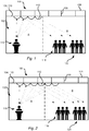
- Fig. 1 discloses an acoustic system 100 according to one embodiment herein.
- the acoustic system 100 comprises a room 102.
- the room 102 may be a class room, a conference room or any other type of ordinary room as defined in ISO 3382-2 in which it is desired to provide improved acoustic properties for speech intelligibility and speaker comfort.
- the room 102 has a first zone A and a second zone B, the separation of which is indicated by the dashed line in the Fig. 1 and the following figures.
- the first zone A is preferably a presentation zone A, in which a presentation position 116 may be arranged.
- the speech is thus preferably emitted from the presentation zone A, either directly from a person/speaker and/or synthetically from a loudspeaker system.
- the second zone B is the intended target of the sound emitted from the first zone A, and is thus preferably an audience zone B.
- the system 100 further comprises a ceiling 104, the ceiling 104 comprising a pluraliy of ceiling tiles 110, 112.
- the ceiling 104 may be a suspended ceiling 104 as is illustrated in Figs 1 and 2 , in which the ceiling tiles 110, 112 are attached to a grid of profiles 106 which is suspended from a structural ceiling 108 of the room 102.
- the ceiling 104 may further be a direct fixed ceiling 104, in which the ceiling tiles 110, 112 are fixed to either directly to a structural ceiling or to a grid of profiles 106 attached closer/directly to the structural ceiling 108.
- the ceiling may furhter be a free hanging ceiling unit 104 in which the ceiling tiles 110, 112 are supported individually from the the structural ceiling 108, for instance by means of wires, without any grid of profiles.
- the ceiling tiles 110, 112 further comprises a first group of ceiling tiles 110 having sound absorbing properties.
- the first group of ceiling tiles 110 may be conventional ceiling tiles 110 and may in one embodiment be manufactured from a mineral fibre material. Rooms provided with sound absorbing ceiling tiles presents certain difficulties for achieving a desired acoustic for achieving high speech intelligibility and speaker comfort. It has been realized that sound absorbing ceilings reduces the sound strength of higher octave frequency bands which are considered important for speech intelligibility, while such ceilings provides less sound absorption for lower sound frequencies that may be detrimental to speech intelligibility.
- the ceiling tiles 110, 112 further comprises a second group of ceiling tiles 112 having sound diffusing properties.
- the second group ceiling tiles 112 will be described in more detail in relation to Figs 9 to 19 .
- the first group of ceiling tiles 110 comprises ceiling tiles being arranged in the second zone B and the second group of ceiling tiles 112 comprises ceiling tiles being arranged in the first zone A and is configured for reflecting sound to the first zone A and to the second zone B.
- all of the second group of ceiling tiles 112 are arranged in the first zone A.
- the second group of ceiling tiles 112 thus provides early sound reflections to the second zone B, in which the audience is positioned.
- the first group of ceiling tiles 110 absorbs sound particularly well in the medium to high speech sound frequency ranges, i.e. from 500 Hz and above.
- the second group of ceiling tiles 112 particularly diffuses and improves reflection of sound having sound frequencies of 500 Hz and above, thus compensating for the sound absorbtion of the first group of ceiling tiles.
- Fig. 2 is another embodiment of the acoustic system 100 shown, in which the second group of ceiling tiles 112 comprises ceiling tiles arranged in the second zone B.
- the ceiling tiles 112 from the second group arranged in second zone B provides additional reflections of sound, particularly to a far position 120 in the second zone B which improves speech intelligibility in the far position 120.
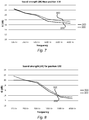
- Fig. 3 shows a comparison diagram of a measured speech clarity Cso in a near position 118 (shown in Figs 1 and 2 ) in the second zone B.
- the acoustic system 100 according to the teachings herein, using ceiling tiles 112 from the second group in the first zone A and the remaining ceiling tiles 110 being sound absorbent ceiling tiles 110 from the first group, is compared to an acoustic system having only sound absorbent ceiling tiles 110 of the first group.
- Table 1 below shows the corresponding measured C 50 values in dB that is plotted in the diagram of Fig. 3 .
- Table 1 C 50 Near position 118 Only absorbent ceiling 200 With Diffusers 300 125 Hz -0,39 -0,15 250 Hz 4,45 4,80 500 Hz 4,13 5,51 1000 Hz 7,46 7,90 2000 Hz 7,80 9,08 4000 Hz 8,29 8,37
- the first graph 200 shows how the C 50 dB level varies with changing frequency when only absorbent ceiling tiles of the first group 110 are fitted, while the second graph 300 shows the corresponding C 50 dB levels when ceiling tiles 112 from the second group are arranged above the presentation position 116 in the first zone A.
- Combining sound absorbing ceiling tiles 110 from the first group with sound diffusing ceiling tiles 112 from the second group provides an increase in C 50 over the entire measured spectrum in the near position 118, i.e. between 125 Hz to 4000 Hz.
- the octave frequency bands of 2000 Hz and 4000 Hz have shown to be particularly important for speech intelligibility and a significant dB increase between these sound frequencies is achieved in the near position 118 by the acoustic system 100 presented herein.
- Fig. 4 shows a comparison diagram of a measured speech clarity C 50 in a far position 120 (shown in Figs 1 and 2 ) in the second zone B.
- the acoustic system 100 according to the teachings herein, using ceiling tiles 112 from the second group in the first zone A and the remaining ceiling tiles 110 being sound absorbent ceiling tiles 110 from the first group, is compared to an acoustic system having only sound absorbent ceiling tiles 110 of the first group.
- Table 2 below shows the corresponding measured Cso values in dB that is plotted in the diagram of Fig. 4 .
- Table 2 C 50 Far position 120 Only absorbent ceiling 200 With Diffusers 300 125 Hz -0,46 1,43 250 Hz 3,76 4,17 500 Hz 4,99 5,53 1000 Hz 4,80 8,02 2000 Hz 4,66 6,28 4000 Hz 4,89 7,43
- the first graph 200 shows measured Cso dB levels in the far position 120 when only sound absorbing ceiling tiles 110 from the first group is arranged in the ceiling 104.
- the second graph 300 shows corresponding Cso dB levels in the far position 120 when ceiling tiles 120 from the second group are fitted to the ceiling 104 in the first zone A above the presentation position 116. For the far position 120, an even more significant improvement is achieved in speech clarity between the octave frequency bands of 2000 Hz and 4000 Hz.
- the second group of ceiling tiles 112 should preferably cover at least 5% of a ceiling area of the ceiling 104 and at most 25% of the ceiling area of the ceiling 104. While also smaller or larger area portions of the ceiling 104 area may be covered by ceiling tiles 112 of the second group, the above limits provides desired functionality of the sound diffusing/reflecting properties of the second group of ceiling tiles 112 whilst avoiding an undesired reduction of the sound absorbing properties of the first group of ceiling tiles 110.
- Fig. 6 shows a comparison diagram of a measured reverberation time T 20 in a near position 118 (shown in Figs 1 and 2 ) in the second zone B.
- the acoustic system 100 according to the teachings herein, using ceiling tiles 112 from the second group in the first zone A and the remaining ceiling tiles 110 being sound absorbent ceiling tiles 110 from the first group, is compared to an acoustic system having only sound absorbent ceiling tiles 110 of the first group.
- Reverberation time T 20 is desired to be kept as low as possible for achieving improved speech intelligibility and speaker comfort, especially for the octave frequency bands from approximately 2000 Hz to 4000 Hz.
- the first graph 200 shows T 20 for an acoustic system having only ceiling tiles 110 from the first group, while the second graph 300 shows T 20 for the acoustic system 100 according to the teachings herein.
- Table 3 shows the corresponding T 20 values (s) that is plotted in the diagram of Fig. 5 .
- Table 3 T 20 Near position 118 Only absorbent ceiling 200 With Diffusers 300 125 Hz 1,006 0,996 250 Hz 0,792 0,817 500 Hz 0,576 0,618 1000 Hz 0,474 0,478 2000 Hz 0,478 0,446 4000 Hz 0,502 0,449
- the reverberation time T 20 is reduced for the important frequencies 2000 Hz and 4000 Hz. This is a non obvious effect of the provision of the ceiling tiles 112 of the second group to the acoustic system 100. In most applications, adding diffusors to an acoustic system generally causes increase reverberation time. However, in the context of the teachings herein where diffusors are combined with absorbent ceiling tiles 110 from the first group, can improvements be achieved also in reverberation time T 20 for the most important octave frequency bands.
- FIG. 6 shows a corresponding comparison diagram for the far position 120.
- the diagram in Fig. 6 compares the acoustic system 100 according to the teachings herein, using ceiling tiles 112 from the second group in the first zone A and the remaining ceiling tiles 110 being sound absorbent ceiling tiles 110 from the first group with an acoustic system having only sound absorbent ceiling tiles 110 of the first group.
- the first graph 200 shows T 20 for an acoustic system having only ceiling tiles 110 from the first group
- the second graph 300 shows T 20 for the acoustic system 100 according to the teachings herein.
- Table 4 below shows the corresponding T 20 values (s) that is plotted in the diagram of Fig. 6 .
- Fig. 7 shows a comparison diagram of a measured sound strength G in a near position 118 (shown in Figs 1 and 2 ) in the second zone B.
- the acoustic system 100 according to the teachings herein, using ceiling tiles 112 from the second group in the first zone A and the remaining ceiling tiles 110 being sound absorbent ceiling tiles 110 from the first group, is compared to an acoustic system having only sound absorbent ceiling tiles 110 of the first group. It is desired to achieve a sound strength G which is appropriate for achieving improved speech intelligibility and speaker comfort, especially for the octave frequency bands from approximately 2000 Hz to 4000 Hz.
- the first graph 200 shows sound strength G for an acoustic system having only ceiling tiles 110 from the first group, while the second graph 300 shows sound strength for the acoustic system 100 according to the teachings herein.
- Table 5 shows the corresponding sound strength G (dB) values that is plotted in the diagram of Fig. 7 .
- Table 5 G Near position 118 Only absorbent ceiling 200 With Diffusers 300 125 Hz 22,3 22,5 250 Hz 20,7 20,8 500 Hz 19,8 20,1 1000 Hz 17,4 18,3 2000 Hz 16,9 17,6 4000 Hz 16,6 17,4
- Fig. 8 shows a corresponding comparison diagram for the far position 120.
- the diagram in Fig. 8 compares the acoustic system 100 according to the teachings herein, using ceiling tiles 112 from the second group in the first zone A and the remaining ceiling tiles 110 being sound absorbent ceiling tiles 110 from the first group with an acoustic system having only sound absorbent ceiling tiles 110 of the first group.
- the first graph 200 shows sound strength G for an acoustic system having only ceiling tiles 110 from the first group
- the second graph 300 shows sound strength G for the acoustic system 100 according to the teachings herein.
- Table 6 below shows the corresponding sound strength G values (dB) that is plotted in the diagram of Fig. 8 .
- Table 6 G Far position 120 Only absorbent ceiling 200 With Diffusers 300 125 Hz 20,0 21,6 250 Hz 20,0 19,9 500 Hz 18,9 19,3 1000 Hz 15,6 16,2 2000 Hz 13,4 13,7 4000 Hz 12,8 13,4
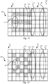
- Fig. 9 shows an acoustic system 100 according to one embodiment.
- the ceiling 104 comprises sound absorbing ceiling tiles 110 of the first group and sound diffusing/reflecting ceiling tiles 112 of the second group, the latter are arranged in a rectangular pattern in the first zone A, i.e. in the presentation zone A.
- No ceiling tiles 112 of the second group are arranged in the second zone B.
- Such an arrangement of the second group of ceiling tiles 112 may be suitable for a room 102 in which the second zone B has a short extension such that the distance between the presentation position 116 and the far position 120 is relatively short. While three lateral/transverse rows of ceiling tiles 112 of the second group are shown, it is to be realized that fewer or more rows of ceiling tiles 112 could be provided in the first zone A.
- Fig. 10 shows yet another embodiment of the acoustic system 100 in which the ceiling 104 is longer and in which the distance from the presentation zone 116 to the far position 120 is longer than in the embodiment of Fig. 9 .
- the arrangement of the second group of ceiling tiles 112 is thus adapted such that ceiling tiles 112 from the second group are also arranged in the second zone B, i.e. in the audience zone B.
- the ceiling tiles 112 will thus provide increased early reflections to the far position 120, compensating for the longer distance and improving sound strength and speech clarity thereto.
- Fig. 11 shows yet another embodiment of the acoustic system 100, in which the second group of ceiling tiles 112 are arranged in longitudinal rows extending from the first zone A into the second zone B. It is to be realized that the rows do not have to extend into the second zone B, for instance if the distance between the presentation position 116 and the far position 120 is sufficiently short such that this is not required. This could for instance be determined by measuring speech clarity, reverberation time and/or sound strength in the far position 120 while changing the extension of the rows until a desired level is found.
- the ceiling tiles 112 can be allowed to be spread out over a larger area of the ceiling 104 and thus provide sound diffusion/reflection over a larger area without exceeding the preferred area limits defined above.
- the rows may further extend longer into the second zone B while keeping within the preferred area limits.
- Fig. 12 shows one embodiment of the acoustic system 100 in which the second group ceiling tiles 112 are arranged in a chess-pattern.
- the chess-pattern arrangement of the second group ceiling tiles 112 provides a more even distribution of the second group ceiling tiles 112 over the ceiling 104 and facilitates even diffusion/reflection.
- arranging the second group ceiling tiles 112 in a chess pattern allows spreading the ceiling tiles 112 over a larger area while keeping within the area ratio limits specified above.
- a second group ceiling tile 112 is shown in a side view.
- the ceiling tile 112 is shown attached to/supported by a grid of profiles 106.
- the ceiling tile 112 may for this purpose comprise a base 126, the base 126 may be formed integrally with the ceiling tile 112 or as a separate part that is connected to the rest of the ceiling tile 112.
- the second group ceiling tile 112 is provided with a front surface 114, the front surface 114 being configured to face the room 102.
- the second group ceiling tile 112 base 126 may be manufactured from a wooden material or a wood based material.
- the front surface 114 may be formed by a sheet material such as hard board material. Other materials could however also be used for manufacturing the second type ceiling tile 112, e.g. metallic materials such as steel sheet metal or polymeric or composite materials or any other material that provides satisfactory sound reflecting properties.
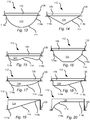
- the front surface 114 shown in Fig. 13 is provided with a single curved convex shape.
- convex is defined as a shape which protrudes outside/below the overall surface of the ceiling 104 while a concave shape is the opposite, i.e. a shape that is recessed inside/above the overall surface of the ceiling 104.
- the curved front surface 114 of the ceiling tile 112 in Fig. 13 is preferably arranged as illustrated in Figs 1 and 2 , i.e. such that the curvature is in the longitudinal direction of the room 102 to facilitate diffusion/reflection of sound both back towards zone A and towards zone B.
- a near end 114a of the ceiling tile 112 front surface 114 should be arranged facing the first zone A or the presentation position or away from the second zone B, while a far end 114b should be arranged facing the second zone B or away from the first zone A.
- the ceiling tile 112 shown in Fig. 13 could further have a double curved front surface 114, such that front surface 114 is semi-spherical. Such a front surface 114 will provide sound diffusion not only in the longitudinal direction of the room but also in lateral/transverse directions.
- the second group ceiling tile 112 may be hollow and having a volume of a hollow portion 124 of the ceiling tile 112 of between 0,02 m 3 and 0,04 m 3, preferably approximately 0,03 m 3 .
- the weight of the ceiling tile 112 can thus be reduced.
- the hollow portion 124 is further especially beneficial if the second group ceiling tile 112 is provided with an opening 122 in the front surface 114, as is illustrated in Figs 22 and 23 .
- the opening 122 should be arranged such that it faces the room 102 and have an opening surface area of between 200 mm 2 and 300 mm 2 , preferably approximately 260-270 mm 2 .
- the opening 122 will allow the second group ceiling tile 112 to function as a resonating absorbent and with the volume of the hollow portion 124 specified above together with the opening 122 surface area will especially low sound frequencies be absorbed. Particularly sound frequencies below 500 Hz, more preferred between 100 Hz and 200 Hz, even more preferred approximately 125 Hz.
- the second group of ceiling tiles 112 in combination with the absorbing ceiling tiles 110 from the first group, as the first group of ceiling tiles 110, which are preferably conventional sound absorbing ceiling tiles 110, are particularly efficient at absorbing sound in octave frequency bands with higher frequencies while generally less effective for sound with a lower frequency.
- the second group of ceiling tiles 112 will thus complement the first group of ceiling tiles 110 in absorbing these frequency bands and thus providing an improved total acoustic property of the acoustic system 100.
- Fig. 14 shows yet another embodiment of a second group ceiling tile 112 in a side view.
- the ceiling tile 112 shown in Fig. 14 has a triangularly shaped convex front surface 114.
- the ceiling tile 112 comprises a near end 114a of the ceiling tile 112 front surface 114 that is configured to be arranged facing the first zone A or the presentation position or away from the second zone B, while a far end 114b of the front surface 114 should be arranged facing the second zone B or away from the first zone A.
- the embodiment shown in Fig. 14 provides a more directed sound reflection, i.e. less sound diffusion/scattering than the embodiment shown in Fig. 13 for instance, given that they are provided with similar surface structure/finish.
- the triangularly shaped ceiling tile 112 could thus be beneficial for instance when an improvement of speech intelligibility of a certain area of the room 102 is desired.
- Fig. 15 shows a side view of a second group ceiling tile 112 having a front surface 114 with an irregular shape.
- a ceiling tile 112 could be formed to achieve a tailored sound diffusion/reflection to each area of the room 102.
- Fig. 16 shows a side view of another embodiment of the second group ceiling tile 112 in which the front surface 114 is convex and multi-faceted.
- the size and shape of each facet of the multi-faceted front surface 114 can be varied which determines the overall sound diffusion/scattering by the ceiling tile 112. For instance, having fewer facets will reduce the diffusive properties of the ceiling tile 112 as the facets will be larger and be oriented at a larger angular separation from each other in comparison to a similar ceiling tile 112 having more facets.
- the multi-faceted front surface 114 thus facilitates providing a desired sound diffusion property to the ceiling tile 112, and to control where the sound is reflected to.
- Fig. 17 shows a side view of yet another embodiment of the second group ceiling tile 112.
- the front surface 114 of the ceiling tile 112 in Fig. 17 has an asymmetrically curved convex shape.
- the curvature increases (i.e. the radius of the curvature decreases) towards the near end 114a of the ceiling tile 112, while it decreases (the radius increases) towards the far end 114b.
- This provides more sound diffusion in the direction of the first zone A, while the diffusion is less for sound reflecting towards the second zone B.
- Fig. 18 shows a side view of yet another embodiment of the second group ceiling tile 112.
- the ceiling tile 112 shown in Fig. 18 comprises an convex asymmetric and at least partially inclined front surface 114, which is further provided with a flat surface at the near end 114a thereof.
- the flat surface may for instance be arranged directly above the presentation position 116 to provide early reflections to improve speaker comfort.
- the inclined portion is arranged at the far end 114b of the ceiling tile 112 and faces the second zone B such that sound is reflected thereto.
- the front surface 114 shape illustrated in Fig. 18 provides less sound diffusion that a continuously curved front surface 114 as shown in e.g. Figs 13 and 17 , but this could be desired to achieve a sufficient sound strength in a particular area of the room 102.
- Fig. 19 shows a side view of one embodiment of the second group ceiling tile 112 in which the front surface 114 is an inclined concave surface 114.
- the inclined concave front surface 114 may be provided with a surface structure/finish that facilitates sound diffusion even though the surface 114 is evenly/uniformly inclined.
- the concave shape facilitates mounting of the ceiling tile 112 in for instance rooms 102 where ceiling height is limited and/or for other reasons ceiling tiles 112 that protrude from the surrounding ceiling 104 are undesired.
- the front surface 114 is inclined such that it faces towards the second zone B, whereby sound is reflected from the first zone A towards the second zone B.
- the ceiling tile 112 could further be arranged behind the presentation position 116 whereby returning sound reflections also to the first zone A can be achieved.
- Fig. 20 shows a side view of one embodiment of the second group ceiling tile 112 in which the front surface 114 is a multi-faceted concave front surface 114.
- the front surface 114 of the ceiling tile 112 is comprises an increasing incline towards the near end 114a thereof. While the front surface 114 is shown having facets, it is to be realized that the increasing incline towards the near end 114a could be achieved with a continuous curvature as well.
- the front surface 114 furhter comprises a flat portion at the far end 114b of the ceiling tile 112, which reduces sound diffusion to the far position 120 of the room 102 and thus improves sound strength at this position which is desirable in certain applications.
- Fig. 21 shows a side view of one embodiment of the second group ceiling tile 112 in which the ceiling tile 112 further comprises a second hollow portion 128, the second hollow portion 128 is preferably in communication with the hollow portion 124.
- the second hollow portion 128 extends above the overall surface of the ceiling 104 and may be beneficial if the desired interior volume as mentioned above cannot be achieved without having a detrimental effect on the shape (and thus the sound diffusive properties) of the second group ceiling tile 112.
- the interior volume of the ceiling tile 112 can thus be increased without affecting the shape of the front surface 114 of the ceiling tile 112.
- the lateral and longitudinal extension of the ceiling tile 112 is generally limited, especially when the ceiling tile 112 is supported by grid of profiles 106.
- the ceiling tiles 110, 112 have the following modular dimensions: 600 x 600 mm or 1200 x 600 mm, in order to fit in existing grid of profiles 106. Achieving both a desired interior volume and a desired shape of the front surface 114 can thus be problematic whilst also having to consider the standardized modular dimensions of the grid of profiles 106.
- Providing a second hollow portion 128 removes some of the limitations that the above relationships could otherwise present in shaping the second group ceiling tile 112.
- the second hollow portion 128 is applicable to all embodiments of the second group ceiling tile 112 disclosed herein.
- Figs. 22 to 24 shows perspective views of embodiments of the second group ceiling tile 112 in which at least one opening 122 is provided in the front surface 114.
- the opening 122 may as shown in Fig. 22 be arranged centrally on the front surface 114, be arranged towards the near end 114a of the ceiling tile 112 as shown in Fig. 23 and towards the far end 114b of the ceiling tile 112 (not shown).
- the opening 122 may further be arranged along the perimeter of the base 126 of the ceiling tile 112 (not shown).
- two openings 122 are provided with one being arranged at the near end 114a and the other at the far end 114b of the ceiling tile 112. It is to be realized that more than two openings 122 could also be provided.
- the total surface area of the opening(s) 122 is between 200 mm 2 and 300 mm 2 , preferably approximately 260 mm 2 .
- the opening(s) 122 allows sound waves to transfer to the inside of the hollow portion 124 (and optionally the second hollow portion 128) whereby frequencies below 500 Hz, preferably approximately 126 Hz, can be absorbed, as mentioned above.
- the volume of the hollow portion 124, or of the hollow portion 124 and the second hollow portion 128 combined, is preferably between 0,02 m 3 and 0,04 m 3, preferably approximately 0,03 m 3 .
- the thickness of the material in the ceiling tile 112 that forms the front surface 114 is between 2 mm and 5 mm, preferably approximately 3 mm, which defines the length channel formed by the opening 122.
- the opening 122 total surface area is, as mentioned, between 200 mm 2 and 300 mm 2 , preferably approximately 260 mm 2 .
- the second group of ceiling tiles 112 will thus complement the first group of ceiling tiles 110 in absorbing the undesired low frequency bands of below 500 Hz thus forming an improved acoustic system.
- the second group of ceiling tiles 112 further facilitates diffusion of sound and provides increased early reflections to both the first zone A and to the second zone B, which increases speech clarity C 50 , increases sound strength G and reduces undesired reverberation time T 20 particularly for the desired octave frequency bands of between 2000 Hz and 4000 Hz.
- the second group ceiling tile 112 having a multi-faceted front surface 114 may have facets that are curved such that they are flat or such that they are individually shaped in a parametric manner. This allows a high degree of adaptation of the sound diffusing properties over the front surface 114 of the second group ceiling tile 112.
- An improved acoustic system 100 that improves speech intelligibility and speaker comfort by enhancing desired octave frequency bands and absorbing undesired octave frequency bands is thus provided.
- ceiling tiles 112 as shown in Fig. 13 could be provided centrally in the first zone A above the presentation zone while ceiling tiles 112 as shown in Fig. 17 could be arranged surrounding the aforementioned ceiling tiles 112 to only mention one example.
Landscapes
- Engineering & Computer Science (AREA)
- Architecture (AREA)
- Physics & Mathematics (AREA)
- Civil Engineering (AREA)
- Structural Engineering (AREA)
- Electromagnetism (AREA)
- Acoustics & Sound (AREA)
- Multimedia (AREA)
- Building Environments (AREA)
- Details Of Audible-Bandwidth Transducers (AREA)
Abstract
Description
- The present invention relates to acoustics and to improvements in audibility and intelligibility of speech for an audience. More specifically, the present invention relates to an acoustic system for improving acoustic quality in a room for speech.
- In rooms which are intended to be used for presentations and/or giving lectures etc, such as a class room or a conference/meeting room, it is desired to provide acoustics which are ideally suited for facilitating the transmission of sound, particularly speech, to the intended audience. The teachings herein pertain particularly to ordinary rooms as defined in ISO 3382-2. Acoustic quality for speech in an ordinary room encompasses not only speech intelligibility for the audience but also speaker comfort, i.e. the perceived comfort that a person speaking receives in the room. In: " Measurement and prediction of voice support and room gain in school classrooms", D. Pelegrin-Garcia, J. Brunskog, V. Lyberg-Åhlander, A. Löfqvist, published in J. Acoust. Soc. Am. 131 (1), January 2012 , is speaker comfort discussed and a parameter for quantification introduced. The parameter voice support is related to sound strength G. There is probably an optimum value but more investigations are needed.
- Early reflections of the sound waves are generally considered favourable for the acoustic quality in a room for speech while late reflections are considered detrimental. A standardized measurement parameter of such early reflections is speech clarity C50, where the relationship between sound reflections before and after 50 ms are observed and where the former is considered early reflections and thus beneficial. Another parameter that is of importance is reverberation of different frequencies of sound, where excessive reverberation or reverberation time, T20, of certain sound frequencies can cause discomfort and/or reduce intelligibility of the speech. Moreover, as mentioned, the sound strength G is also of importance. All these factors/parameters are affected by the general design of the room as well as of if for instance a sound absorbent ceiling is provided in the room.
- In view of that stated above, the object of the present invention is to provide an acoustic system that alleviates some of the problems with prior art solutions and improves speech intelligibility and speaker comfort in a room provided with a sound absorbent ceiling.
- To achieve at least one of the above objects and also other objects that will be evident from the following description, an acoustic system having the features defined in
claim 1 is provided according to the present disclosure. Preferred embodiments of the system will be evident from the dependent claims. - More specifically, there is provided an acoustic system for improving speech intelligibility, the acoustic system comprising a room having a first zone and a second zone. The system further comprising a ceiling of the room, the ceiling comprising a plurality of ceiling tiles. The ceiling tiles comprises a first group of ceiling tiles having sound absorbing properties and a second group of ceiling tiles having sound diffusing properties. The first group of ceiling tiles comprises ceiling tiles being arranged in the second zone and the second group of ceiling tiles comprises ceiling tiles being arranged in the first zone and being configured for reflecting sound to the first zone and to the second zone. The sound diffusing second group of ceiling tiles arranged in the first zone provides early reflections to both the first zone, which may be a presentation zone, which improves speaker comfort. Further still, the early reflections provided to the second zone, which may be an audience zone, improves the speech clarity and sound strength in the second zone which improves speech intelligibility. Moreover, reverberation time for octave frequency bands which are considered relevant for speech intelligibility are also reduced.
- The ceiling may be a suspended ceiling, a direct fixed ceiling or a free hanging ceiling unit.
- In one embodiment, the ceiling comprises a grid of profiles supporting the ceiling tiles.
- The second group of ceiling tiles may further cover at least 5% of a ceiling area of the ceiling. The second group of ceiling tiles may further still cover at the most 25% of a ceiling area of the ceiling. The aforementioned ratios provide a desired balance where the overall sound absorbing functionality of the first group of ceiling tiles is maintained while the second group of ceiling tiles provides a significant improvement in speech intelligibility and improved speaker comfort.
- The first group of ceiling tiles may comprise ceiling tiles mounted in the second zone.
- The second group of ceiling tiles may further be hollow having a front surface provided with at least one opening facing the room. The volume of a hollow portion of the ceiling tile may be between 0,02 m3 and 0,04 m3, preferably approximately 0,03 m3. The hollow shape of each second group ceiling tile and the at least one opening form a resonance chamber in each second group ceiling tile that allows it to absorb octave frequency bands which for instance the first group of ceiling tiles are less efficient at absorbing. The overall acoustic properties of the acoustic system are thus improved.
- The at least one opening may further have an opening surface area of between 200 mm2 and 300 mm2, preferably approximately 260 mm2. The aforementioned surface area together with the structure and volume of the hollow portion of the second group ceiling tiles provides improved absorption of low sound frequencies, typically below 500 Hz, more preferably approximately 125 Hz.
- Moreover, the second group of ceiling tiles may be configured to absorb sound having a sound frequency below 500 Hz, preferably approximately 125 Hz. Sound frequencies below 500 Hz, especially around 125 Hz, are typically difficult for a regular sound absorbent ceiling tile, such as those of the first group, to absorb. Furthermore, such low frequencies are not considered beneficial for speech intelligibility. The second group of ceiling tiles thus reduces such undesired low sound frequencies thus complementing the first group of ceiling tiles.
- In one embodiment, the presentation zone covers a presentation position from which a speaker, i.e. a person, is intended to address an audience. Furthermore, ceiling tiles from the second group of ceiling tiles may be arranged directly above the presentation position. Having second group ceiling tiles arranged directly above the speaker provides a significant increase in the early reflections that the speaker can receive which improves speaker comfort.
- Ceiling tiles from the second group of ceiling tiles may further be arranged covering an area of the suspended ceiling from the presentation position extending towards the second zone. Further still, ceiling tiles from the second group of ceiling tiles may be arranged in the audience zone. Extending the second group of ceiling tiles from the first zone towards and even into the second zone increases the early reflections and the sound strength that can be provided to the second zone.
- Ceiling tiles from the first group of ceiling tiles may further be arranged in the first zone.
- The second group of ceiling tiles may comprises ceiling tiles having a front surface facing the room having a shape selected from the group comprising: a single curved convex front surface, a double curved convex front surface, a multi-faceted convex front surface, an asymmetric at least partially inclined front surface, an asymmetrically curved convex front surface, an inclined concave front surface, an at least partially curved concave front surface and a multi-faceted concave front surface.
- Generally, all terms used in the claims are to be interpreted according to their ordinary meaning in the technical field, unless explicitly defined otherwise herein. All references to "a/an/the [element, device, component, means, step, etc]" are to be interpreted openly as referring to at least one instance of said element, device, component, means, step, etc., unless explicitly stated otherwise. The steps of any method disclosed herein do not have to be performed in the exact order disclosed, unless explicitly stated.
- The above, as well as additional objects, features and advantages of the present invention, will be better understood through the following illustrative and non-limiting detailed description of preferred embodiments of the present invention, with reference to the appended drawings, where the same reference numerals will be used for similar elements, wherein:
-
Fig. 1 discloses a side view of anacoustic system 100 according to one embodiment. -
Fig. 2 discloses a side view of anacoustic system 100 according to one embodiment. -
Fig. 3 discloses a diagram of measured speech clarity Cso in a near position in a room. -
Fig. 4 discloses a diagram of measured speech clarity Cso in a far position in a room. -
Fig. 5 discloses a diagram of measured reverberation time T20 in a near position in a room. -
Fig. 6 discloses a diagram of measured reverberation time T20 in a far position in a room. -
Fig. 7 discloses a diagram of measured sound strength G in a near position in a room. -
Fig. 8 discloses a diagram of measured sound strength G in a far position in a room. -
Fig. 9 discloses a top view of an acoustic system according to one embodiment. -
Fig. 10 discloses a top view of an acoustic system according to one embodiment. -
Fig. 11 discloses a top view of an acoustic system according to one embodiment. -
Fig. 12 discloses a top view of an acoustic system according to one embodiment. -
Fig. 13 discloses a side view of a second group ceiling tile according to one embodiment. -
Fig. 14 discloses a side view of a second group ceiling tile according to one embodiment. -
Fig. 15 discloses a side view of a second group ceiling tile according to one embodiment. -
Fig. 16 discloses a side view of a second group ceiling tile according to one embodiment. -
Fig. 17 discloses a side view of a second group ceiling tile according to one embodiment. -
Fig. 18 discloses a side view of a second group ceiling tile according to one embodiment. -
Fig. 19 discloses a side view of a second group ceiling tile according to one embodiment. -
Fig. 20 discloses a side view of a second group ceiling tile according to one embodiment. -
Fig. 21 discloses a side view of a second group ceiling tile according to one embodiment. -
Fig. 22 discloses a perspective view of a second group ceiling tile according to one embodiment. -
Fig. 23 discloses a perspective view of a second group ceiling tile according to one embodiment. -
Fig. 24 discloses a perspective view of a second group ceiling tile according to one embodiment. - The present invention will now be described more fully hereinafter with reference to the accompanying drawings, in which currently preferred embodiments of the invention are shown. This invention may, however, be embodied in many different forms and should not be construed as limited to the embodiments set forth herein; rather, these embodiments are provided for thoroughness and completeness, and fully convey the scope of the invention to the skilled person.
-
Fig. 1 discloses anacoustic system 100 according to one embodiment herein. Theacoustic system 100 comprises aroom 102. Theroom 102 may be a class room, a conference room or any other type of ordinary room as defined in ISO 3382-2 in which it is desired to provide improved acoustic properties for speech intelligibility and speaker comfort. - The
room 102 has a first zone A and a second zone B, the separation of which is indicated by the dashed line in theFig. 1 and the following figures. The first zone A is preferably a presentation zone A, in which apresentation position 116 may be arranged. The speech is thus preferably emitted from the presentation zone A, either directly from a person/speaker and/or synthetically from a loudspeaker system. - The second zone B is the intended target of the sound emitted from the first zone A, and is thus preferably an audience zone B.
- The
system 100 further comprises aceiling 104, theceiling 104 comprising a pluraliy ofceiling tiles ceiling 104 may be a suspendedceiling 104 as is illustrated inFigs 1 and 2 , in which theceiling tiles profiles 106 which is suspended from astructural ceiling 108 of theroom 102. Theceiling 104 may further be a direct fixedceiling 104, in which theceiling tiles profiles 106 attached closer/directly to thestructural ceiling 108. The ceiling may furhter be a freehanging ceiling unit 104 in which theceiling tiles structural ceiling 108, for instance by means of wires, without any grid of profiles. - The
ceiling tiles ceiling tiles 110 having sound absorbing properties. The first group ofceiling tiles 110 may beconventional ceiling tiles 110 and may in one embodiment be manufactured from a mineral fibre material. Rooms provided with sound absorbing ceiling tiles presents certain difficulties for achieving a desired acoustic for achieving high speech intelligibility and speaker comfort. It has been realized that sound absorbing ceilings reduces the sound strength of higher octave frequency bands which are considered important for speech intelligibility, while such ceilings provides less sound absorption for lower sound frequencies that may be detrimental to speech intelligibility. - The
ceiling tiles ceiling tiles 112 having sound diffusing properties. The secondgroup ceiling tiles 112 will be described in more detail in relation toFigs 9 to 19 . - The first group of
ceiling tiles 110 comprises ceiling tiles being arranged in the second zone B and the second group ofceiling tiles 112 comprises ceiling tiles being arranged in the first zone A and is configured for reflecting sound to the first zone A and to the second zone B. In the embodiment shown inFig. 1 , all of the second group ofceiling tiles 112 are arranged in the first zone A. - The second group of
ceiling tiles 112 thus provides early sound reflections to the second zone B, in which the audience is positioned. The first group ofceiling tiles 110 absorbs sound particularly well in the medium to high speech sound frequency ranges, i.e. from 500 Hz and above. The second group ofceiling tiles 112 particularly diffuses and improves reflection of sound having sound frequencies of 500 Hz and above, thus compensating for the sound absorbtion of the first group of ceiling tiles. - The comfort for an eventual speaker in the
presentation position 116 is improved by the early reflections indicated inFig. 1 as the whole double arrowed lines. - In
Fig. 2 is another embodiment of theacoustic system 100 shown, in which the second group ofceiling tiles 112 comprises ceiling tiles arranged in the second zone B. Theceiling tiles 112 from the second group arranged in second zone B provides additional reflections of sound, particularly to afar position 120 in the second zone B which improves speech intelligibility in thefar position 120. -
Fig. 3 shows a comparison diagram of a measured speech clarity Cso in a near position 118 (shown inFigs 1 and 2 ) in the second zone B. Theacoustic system 100 according to the teachings herein, usingceiling tiles 112 from the second group in the first zone A and the remainingceiling tiles 110 being soundabsorbent ceiling tiles 110 from the first group, is compared to an acoustic system having only soundabsorbent ceiling tiles 110 of the first group. - Speech clarity C50 is, as mentioned above, the relationship between early and late reflections and is more specifically defined by the following formula, in which h= measured impulse response:

- Table 1 below shows the corresponding measured C50 values in dB that is plotted in the diagram of
Fig. 3 .Table 1 C50 Near position 118Only absorbent ceiling 200With Diffusers 300125 Hz -0,39 -0,15 250 Hz 4,45 4,80 500 Hz 4,13 5,51 1000 Hz 7,46 7,90 2000 Hz 7,80 9,08 4000 Hz 8,29 8,37 - The
first graph 200 shows how the C50 dB level varies with changing frequency when only absorbent ceiling tiles of thefirst group 110 are fitted, while thesecond graph 300 shows the corresponding C50 dB levels whenceiling tiles 112 from the second group are arranged above thepresentation position 116 in the first zone A. Combining sound absorbingceiling tiles 110 from the first group with sound diffusingceiling tiles 112 from the second group provides an increase in C50 over the entire measured spectrum in thenear position 118, i.e. between 125 Hz to 4000 Hz. - The octave frequency bands of 2000 Hz and 4000 Hz have shown to be particularly important for speech intelligibility and a significant dB increase between these sound frequencies is achieved in the
near position 118 by theacoustic system 100 presented herein. -
Fig. 4 shows a comparison diagram of a measured speech clarity C50 in a far position 120 (shown inFigs 1 and 2 ) in the second zone B. Theacoustic system 100 according to the teachings herein, usingceiling tiles 112 from the second group in the first zone A and the remainingceiling tiles 110 being soundabsorbent ceiling tiles 110 from the first group, is compared to an acoustic system having only soundabsorbent ceiling tiles 110 of the first group. - Table 2 below shows the corresponding measured Cso values in dB that is plotted in the diagram of
Fig. 4 .Table 2 C50 Far position 120 Only absorbent ceiling 200With Diffusers 300125 Hz -0,46 1,43 250 Hz 3,76 4,17 500 Hz 4,99 5,53 1000 Hz 4,80 8,02 2000 Hz 4,66 6,28 4000 Hz 4,89 7,43 - The
first graph 200 shows measured Cso dB levels in thefar position 120 when only sound absorbingceiling tiles 110 from the first group is arranged in theceiling 104. Thesecond graph 300 shows corresponding Cso dB levels in thefar position 120 whenceiling tiles 120 from the second group are fitted to theceiling 104 in the first zone A above thepresentation position 116. For thefar position 120, an even more significant improvement is achieved in speech clarity between the octave frequency bands of 2000 Hz and 4000 Hz. - The second group of
ceiling tiles 112 should preferably cover at least 5% of a ceiling area of theceiling 104 and at most 25% of the ceiling area of theceiling 104. While also smaller or larger area portions of theceiling 104 area may be covered byceiling tiles 112 of the second group, the above limits provides desired functionality of the sound diffusing/reflecting properties of the second group ofceiling tiles 112 whilst avoiding an undesired reduction of the sound absorbing properties of the first group ofceiling tiles 110. -
Fig. 6 shows a comparison diagram of a measured reverberation time T20 in a near position 118 (shown inFigs 1 and 2 ) in the second zone B. Theacoustic system 100 according to the teachings herein, usingceiling tiles 112 from the second group in the first zone A and the remainingceiling tiles 110 being soundabsorbent ceiling tiles 110 from the first group, is compared to an acoustic system having only soundabsorbent ceiling tiles 110 of the first group. Reverberation time T20 is desired to be kept as low as possible for achieving improved speech intelligibility and speaker comfort, especially for the octave frequency bands from approximately 2000 Hz to 4000 Hz. Thefirst graph 200 shows T20 for an acoustic system havingonly ceiling tiles 110 from the first group, while thesecond graph 300 shows T20 for theacoustic system 100 according to the teachings herein. Table 3 below shows the corresponding T20 values (s) that is plotted in the diagram ofFig. 5 .Table 3 T20 Near position 118Only absorbent ceiling 200With Diffusers 300125 Hz 1,006 0,996 250 Hz 0,792 0,817 500 Hz 0,576 0,618 1000 Hz 0,474 0,478 2000 Hz 0,478 0,446 4000 Hz 0,502 0,449 - It can be seen that the reverberation time T20 is reduced for the
important frequencies 2000 Hz and 4000 Hz. This is a non obvious effect of the provision of theceiling tiles 112 of the second group to theacoustic system 100. In most applications, adding diffusors to an acoustic system generally causes increase reverberation time. However, in the context of the teachings herein where diffusors are combined withabsorbent ceiling tiles 110 from the first group, can improvements be achieved also in reverberation time T20 for the most important octave frequency bands. - This extends also to
Fig. 6 , which shows a corresponding comparison diagram for thefar position 120. I.e., the diagram inFig. 6 compares theacoustic system 100 according to the teachings herein, usingceiling tiles 112 from the second group in the first zone A and the remainingceiling tiles 110 being soundabsorbent ceiling tiles 110 from the first group with an acoustic system having only soundabsorbent ceiling tiles 110 of the first group. Thefirst graph 200 shows T20 for an acoustic system havingonly ceiling tiles 110 from the first group, while thesecond graph 300 shows T20 for theacoustic system 100 according to the teachings herein. Table 4 below shows the corresponding T20 values (s) that is plotted in the diagram ofFig. 6 .Table 4 T20 Far position 120 Only absorbent ceiling 200With Diffusers 300125 Hz 0,747 0,732 250 Hz 0,841 0,858 500 Hz 0,633 0,596 1000 Hz 0,503 0,525 2000 Hz 0,498 0,463 4000 Hz 0,530 0,475 - Also in the
far position 120 can a decrease in the reverberation time T20 be observed for thefrequencies 2000 Hz and 4000 Hz compared to a prior art acoustic system where only soundabsorbent ceiling tiles 110 of the first group are used. -
Fig. 7 shows a comparison diagram of a measured sound strength G in a near position 118 (shown inFigs 1 and 2 ) in the second zone B. Theacoustic system 100 according to the teachings herein, usingceiling tiles 112 from the second group in the first zone A and the remainingceiling tiles 110 being soundabsorbent ceiling tiles 110 from the first group, is compared to an acoustic system having only soundabsorbent ceiling tiles 110 of the first group. It is desired to achieve a sound strength G which is appropriate for achieving improved speech intelligibility and speaker comfort, especially for the octave frequency bands from approximately 2000 Hz to 4000 Hz. Thefirst graph 200 shows sound strength G for an acoustic system havingonly ceiling tiles 110 from the first group, while thesecond graph 300 shows sound strength for theacoustic system 100 according to the teachings herein. Table 5 below shows the corresponding sound strength G (dB) values that is plotted in the diagram ofFig. 7 .Table 5 G Near position 118Only absorbent ceiling 200With Diffusers 300125 Hz 22,3 22,5 250 Hz 20,7 20,8 500 Hz 19,8 20,1 1000 Hz 17,4 18,3 2000 Hz 16,9 17,6 4000 Hz 16,6 17,4 - As can be seen in
Fig. 7 , and in the corresponding Table 5, an increase in sound strength G is achieved particularly for thefrequencies 2000 Hz and 4000 Hz. -
Fig. 8 shows a corresponding comparison diagram for thefar position 120. I.e., the diagram inFig. 8 compares theacoustic system 100 according to the teachings herein, usingceiling tiles 112 from the second group in the first zone A and the remainingceiling tiles 110 being soundabsorbent ceiling tiles 110 from the first group with an acoustic system having only soundabsorbent ceiling tiles 110 of the first group. Thefirst graph 200 shows sound strength G for an acoustic system havingonly ceiling tiles 110 from the first group, while thesecond graph 300 shows sound strength G for theacoustic system 100 according to the teachings herein. Table 6 below shows the corresponding sound strength G values (dB) that is plotted in the diagram ofFig. 8 .Table 6 G Far position 120Only absorbent ceiling 200With Diffusers 300125 Hz 20,0 21,6 250 Hz 20,0 19,9 500 Hz 18,9 19,3 1000 Hz 15,6 16,2 2000 Hz 13,4 13,7 4000 Hz 12,8 13,4 - While the increase in sound strength G compared to the prior art system is not as significant in the
far position 120 as it is in thenear position 118, a noticeable increase is still achieved for the desired frequencies of 2000 Hz and 4000 Hz. -
Fig. 9 shows anacoustic system 100 according to one embodiment. Theceiling 104 comprises sound absorbingceiling tiles 110 of the first group and sound diffusing/reflectingceiling tiles 112 of the second group, the latter are arranged in a rectangular pattern in the first zone A, i.e. in the presentation zone A. Noceiling tiles 112 of the second group are arranged in the second zone B. Such an arrangement of the second group ofceiling tiles 112 may be suitable for aroom 102 in which the second zone B has a short extension such that the distance between thepresentation position 116 and thefar position 120 is relatively short. While three lateral/transverse rows ofceiling tiles 112 of the second group are shown, it is to be realized that fewer or more rows ofceiling tiles 112 could be provided in the first zone A. -
Fig. 10 shows yet another embodiment of theacoustic system 100 in which theceiling 104 is longer and in which the distance from thepresentation zone 116 to thefar position 120 is longer than in the embodiment ofFig. 9 . The arrangement of the second group ofceiling tiles 112 is thus adapted such thatceiling tiles 112 from the second group are also arranged in the second zone B, i.e. in the audience zone B. Theceiling tiles 112 will thus provide increased early reflections to thefar position 120, compensating for the longer distance and improving sound strength and speech clarity thereto. -
Fig. 11 shows yet another embodiment of theacoustic system 100, in which the second group ofceiling tiles 112 are arranged in longitudinal rows extending from the first zone A into the second zone B. It is to be realized that the rows do not have to extend into the second zone B, for instance if the distance between thepresentation position 116 and thefar position 120 is sufficiently short such that this is not required. This could for instance be determined by measuring speech clarity, reverberation time and/or sound strength in thefar position 120 while changing the extension of the rows until a desired level is found. - By arranging the second
group ceiling tiles 112 in individual longitudinal rows, theceiling tiles 112 can be allowed to be spread out over a larger area of theceiling 104 and thus provide sound diffusion/reflection over a larger area without exceeding the preferred area limits defined above. The rows may further extend longer into the second zone B while keeping within the preferred area limits. -
Fig. 12 shows one embodiment of theacoustic system 100 in which the secondgroup ceiling tiles 112 are arranged in a chess-pattern. The chess-pattern arrangement of the secondgroup ceiling tiles 112 provides a more even distribution of the secondgroup ceiling tiles 112 over theceiling 104 and facilitates even diffusion/reflection. As for the embodiment shown inFig. 11 , arranging the secondgroup ceiling tiles 112 in a chess pattern allows spreading theceiling tiles 112 over a larger area while keeping within the area ratio limits specified above. - Turning now to
Fig. 13 in which one embodiment of a secondgroup ceiling tile 112 is shown in a side view. Theceiling tile 112 is shown attached to/supported by a grid ofprofiles 106. Theceiling tile 112 may for this purpose comprise a base 126, thebase 126 may be formed integrally with theceiling tile 112 or as a separate part that is connected to the rest of theceiling tile 112. The secondgroup ceiling tile 112 is provided with afront surface 114, thefront surface 114 being configured to face theroom 102. The secondgroup ceiling tile 112base 126 may be manufactured from a wooden material or a wood based material. Thefront surface 114 may be formed by a sheet material such as hard board material. Other materials could however also be used for manufacturing the secondtype ceiling tile 112, e.g. metallic materials such as steel sheet metal or polymeric or composite materials or any other material that provides satisfactory sound reflecting properties. - To achieve a desired diffusion/reflection of sound waves, the
front surface 114 shown inFig. 13 is provided with a single curved convex shape. In the present disclosure, convex is defined as a shape which protrudes outside/below the overall surface of theceiling 104 while a concave shape is the opposite, i.e. a shape that is recessed inside/above the overall surface of theceiling 104. - The curved
front surface 114 of theceiling tile 112 inFig. 13 is preferably arranged as illustrated inFigs 1 and 2 , i.e. such that the curvature is in the longitudinal direction of theroom 102 to facilitate diffusion/reflection of sound both back towards zone A and towards zone B. In other words, anear end 114a of theceiling tile 112front surface 114 should be arranged facing the first zone A or the presentation position or away from the second zone B, while afar end 114b should be arranged facing the second zone B or away from the first zone A. - The
ceiling tile 112 shown inFig. 13 could further have a double curvedfront surface 114, such thatfront surface 114 is semi-spherical. Such afront surface 114 will provide sound diffusion not only in the longitudinal direction of the room but also in lateral/transverse directions. - The second
group ceiling tile 112 may be hollow and having a volume of ahollow portion 124 of theceiling tile 112 of between 0,02 m3 and 0,04 m3, preferably approximately 0,03 m3. The weight of theceiling tile 112 can thus be reduced. Thehollow portion 124 is further especially beneficial if the secondgroup ceiling tile 112 is provided with anopening 122 in thefront surface 114, as is illustrated inFigs 22 and 23 . - The
opening 122 should be arranged such that it faces theroom 102 and have an opening surface area of between 200 mm2 and 300 mm2, preferably approximately 260-270 mm2. Theopening 122 will allow the secondgroup ceiling tile 112 to function as a resonating absorbent and with the volume of thehollow portion 124 specified above together with theopening 122 surface area will especially low sound frequencies be absorbed. Particularly sound frequencies below 500 Hz, more preferred between 100 Hz and 200 Hz, even more preferred approximately 125 Hz. - This is especially beneficial when considering the second group of
ceiling tiles 112 in combination with the absorbingceiling tiles 110 from the first group, as the first group ofceiling tiles 110, which are preferably conventional sound absorbingceiling tiles 110, are particularly efficient at absorbing sound in octave frequency bands with higher frequencies while generally less effective for sound with a lower frequency. Such low octave frequency bands as between 100 Hz and 200 Hz are further not desirable for improving speech clarity/intelligibility, the second group ofceiling tiles 112 will thus complement the first group ofceiling tiles 110 in absorbing these frequency bands and thus providing an improved total acoustic property of theacoustic system 100.Fig. 14 shows yet another embodiment of a secondgroup ceiling tile 112 in a side view. The embodiments shown inFigs 14 to 21 shares most features with the embodiment shown inFig. 9 , emphasis below will thus be made on the unique features for each embodiment. The description of features in relation toFig. 9 in the aforementioned, and of features of embodiments inFigs 14 to 21 in the following, is thus unless stated otherwise applicable to each embodiment of the secondgroup ceiling tile 112 disclosed herein. - The
ceiling tile 112 shown inFig. 14 has a triangularly shaped convexfront surface 114. Theceiling tile 112 comprises anear end 114a of theceiling tile 112front surface 114 that is configured to be arranged facing the first zone A or the presentation position or away from the second zone B, while afar end 114b of thefront surface 114 should be arranged facing the second zone B or away from the first zone A. The embodiment shown inFig. 14 provides a more directed sound reflection, i.e. less sound diffusion/scattering than the embodiment shown inFig. 13 for instance, given that they are provided with similar surface structure/finish. The triangularly shapedceiling tile 112 could thus be beneficial for instance when an improvement of speech intelligibility of a certain area of theroom 102 is desired. -
Fig. 15 shows a side view of a secondgroup ceiling tile 112 having afront surface 114 with an irregular shape. Such aceiling tile 112 could be formed to achieve a tailored sound diffusion/reflection to each area of theroom 102. -
Fig. 16 shows a side view of another embodiment of the secondgroup ceiling tile 112 in which thefront surface 114 is convex and multi-faceted. The size and shape of each facet of the multi-facetedfront surface 114 can be varied which determines the overall sound diffusion/scattering by theceiling tile 112. For instance, having fewer facets will reduce the diffusive properties of theceiling tile 112 as the facets will be larger and be oriented at a larger angular separation from each other in comparison to asimilar ceiling tile 112 having more facets. The multi-facetedfront surface 114 thus facilitates providing a desired sound diffusion property to theceiling tile 112, and to control where the sound is reflected to. -
Fig. 17 shows a side view of yet another embodiment of the secondgroup ceiling tile 112. Thefront surface 114 of theceiling tile 112 inFig. 17 has an asymmetrically curved convex shape. The curvature increases (i.e. the radius of the curvature decreases) towards thenear end 114a of theceiling tile 112, while it decreases (the radius increases) towards thefar end 114b. This provides more sound diffusion in the direction of the first zone A, while the diffusion is less for sound reflecting towards the second zone B. This could be beneficial in certain applications where it is for instance determined that thepresentation zone 116 receives too high sound strength while thefar position 120 recieves a too low sound strength. Having less sound diffusion for the sound reflecting towards the second zone B will allow improvements in the sound strength in the second zone B, while sound strength can be reduced in the first zone A by the increased diffusion in that direction. -
Fig. 18 shows a side view of yet another embodiment of the secondgroup ceiling tile 112. Theceiling tile 112 shown inFig. 18 comprises an convex asymmetric and at least partially inclinedfront surface 114, which is further provided with a flat surface at thenear end 114a thereof. The flat surface may for instance be arranged directly above thepresentation position 116 to provide early reflections to improve speaker comfort. The inclined portion is arranged at thefar end 114b of theceiling tile 112 and faces the second zone B such that sound is reflected thereto. Thefront surface 114 shape illustrated inFig. 18 provides less sound diffusion that a continuously curvedfront surface 114 as shown in e.g.Figs 13 and 17 , but this could be desired to achieve a sufficient sound strength in a particular area of theroom 102. -
Fig. 19 shows a side view of one embodiment of the secondgroup ceiling tile 112 in which thefront surface 114 is an inclinedconcave surface 114. The inclined concavefront surface 114 may be provided with a surface structure/finish that facilitates sound diffusion even though thesurface 114 is evenly/uniformly inclined. The concave shape facilitates mounting of theceiling tile 112 in forinstance rooms 102 where ceiling height is limited and/or for otherreasons ceiling tiles 112 that protrude from the surroundingceiling 104 are undesired. Thefront surface 114 is inclined such that it faces towards the second zone B, whereby sound is reflected from the first zone A towards the second zone B. Theceiling tile 112 could further be arranged behind thepresentation position 116 whereby returning sound reflections also to the first zone A can be achieved. -
Fig. 20 shows a side view of one embodiment of the secondgroup ceiling tile 112 in which thefront surface 114 is a multi-faceted concavefront surface 114. Thefront surface 114 of theceiling tile 112 is comprises an increasing incline towards thenear end 114a thereof. While thefront surface 114 is shown having facets, it is to be realized that the increasing incline towards thenear end 114a could be achieved with a continuous curvature as well. Thefront surface 114 furhter comprises a flat portion at thefar end 114b of theceiling tile 112, which reduces sound diffusion to thefar position 120 of theroom 102 and thus improves sound strength at this position which is desirable in certain applications. -
Fig. 21 shows a side view of one embodiment of the secondgroup ceiling tile 112 in which theceiling tile 112 further comprises a secondhollow portion 128, the secondhollow portion 128 is preferably in communication with thehollow portion 124. The secondhollow portion 128 extends above the overall surface of theceiling 104 and may be beneficial if the desired interior volume as mentioned above cannot be achieved without having a detrimental effect on the shape (and thus the sound diffusive properties) of the secondgroup ceiling tile 112. The interior volume of theceiling tile 112 can thus be increased without affecting the shape of thefront surface 114 of theceiling tile 112. - The lateral and longitudinal extension of the
ceiling tile 112 is generally limited, especially when theceiling tile 112 is supported by grid ofprofiles 106. Typically, theceiling tiles profiles 106. Achieving both a desired interior volume and a desired shape of thefront surface 114 can thus be problematic whilst also having to consider the standardized modular dimensions of the grid ofprofiles 106. Providing a secondhollow portion 128 removes some of the limitations that the above relationships could otherwise present in shaping the secondgroup ceiling tile 112. The secondhollow portion 128 is applicable to all embodiments of the secondgroup ceiling tile 112 disclosed herein. -
Figs. 22 to 24 shows perspective views of embodiments of the secondgroup ceiling tile 112 in which at least oneopening 122 is provided in thefront surface 114. Theopening 122 may as shown inFig. 22 be arranged centrally on thefront surface 114, be arranged towards thenear end 114a of theceiling tile 112 as shown inFig. 23 and towards thefar end 114b of the ceiling tile 112 (not shown). Theopening 122 may further be arranged along the perimeter of thebase 126 of the ceiling tile 112 (not shown). - In one embodiment, as shown in
Fig. 24 , twoopenings 122 are provided with one being arranged at thenear end 114a and the other at thefar end 114b of theceiling tile 112. It is to be realized that more than twoopenings 122 could also be provided. The total surface area of the opening(s) 122 is between 200 mm2 and 300 mm2, preferably approximately 260 mm2. - The opening(s) 122 allows sound waves to transfer to the inside of the hollow portion 124 (and optionally the second hollow portion 128) whereby frequencies below 500 Hz, preferably approximately 126 Hz, can be absorbed, as mentioned above. The volume of the
hollow portion 124 together with the thickness of the ceiling tile material that constitutes thefront surface 114 and the area of the opening(s) 122 defines the resonance frequency of theceiling tile 112 according to the following formula:
opening 122, L=length of the channel formed by the opening 122 from outside to inside offront surface 114, V=volume ofhollow portion 124 or hollow portion and secondhollow portion 128 combined. - The volume of the
hollow portion 124, or of thehollow portion 124 and the secondhollow portion 128 combined, is preferably between 0,02 m3 and 0,04 m3, preferably approximately 0,03 m3. The thickness of the material in theceiling tile 112 that forms thefront surface 114 is between 2 mm and 5 mm, preferably approximately 3 mm, which defines the length channel formed by theopening 122. Theopening 122 total surface area is, as mentioned, between 200 mm2 and 300 mm2, preferably approximately 260 mm2. - The second group of
ceiling tiles 112 will thus complement the first group ofceiling tiles 110 in absorbing the undesired low frequency bands of below 500 Hz thus forming an improved acoustic system. The second group ofceiling tiles 112 further facilitates diffusion of sound and provides increased early reflections to both the first zone A and to the second zone B, which increases speech clarity C50, increases sound strength G and reduces undesired reverberation time T20 particularly for the desired octave frequency bands of between 2000 Hz and 4000 Hz. - What is further shown in
Fig. 24 is that the secondgroup ceiling tile 112 having a multi-facetedfront surface 114 may have facets that are curved such that they are flat or such that they are individually shaped in a parametric manner. This allows a high degree of adaptation of the sound diffusing properties over thefront surface 114 of the secondgroup ceiling tile 112. - An improved
acoustic system 100 that improves speech intelligibility and speaker comfort by enhancing desired octave frequency bands and absorbing undesired octave frequency bands is thus provided. - It is to be realized that while each embodiment of the second
group ceiling tile 112 is described separately above, theceiling 104 could be provided with any combination of the different embodiments of the secondgroup ceiling tiles 112. For instance,ceiling tiles 112 as shown inFig. 13 could be provided centrally in the first zone A above the presentation zone whileceiling tiles 112 as shown inFig. 17 could be arranged surrounding theaforementioned ceiling tiles 112 to only mention one example. - It will be appreciated that the present invention is not limited to the embodiments shown. Several modifications and variations are thus conceivable within the scope of the invention which thus is exclusively defined by the appended claims.
Claims (16)
- An acoustic system (100) for improving the acoustic quality in a room (102) for speech, the acoustic system (100) comprising a room (102) having a first zone (A) and a second zone (B), the system further comprising a ceiling (104) of the room (102), the ceiling (104) comprising a plurality of ceiling tiles (110, 112), wherein the ceiling tiles comprises a first group of ceiling tiles (110) having sound absorbing properties and a second group of ceiling tiles (112) having sound diffusing properties, wherein the first group of ceiling tiles (110) comprises ceiling tiles being arranged in the second zone (B) and the second group of ceiling tiles (112) comprises ceiling tiles being arranged in the first zone (A) and being configured for reflecting sound to the first zone (A) and to the second zone (B).
- The acoustic system (100) according to claim 1, wherein the first zone (A) is a presentation zone (A) and the second zone (B) is an audience zone (B).
- The acoustic system (100) according to claim 1 or 2, wherein the ceiling (104) is a suspended ceiling (104), a direct fixed ceiling (104) or a free hanging ceiling unit (104).
- The acoustic system (100) according to any one of the preceding claims, wherein the ceiling (104) comprises a grid of profiles (106) supporting the ceiling tiles (110, 112).
- The acoustic system (100) according to any one of the preceding claims, wherein the second group of ceiling tiles (112) covers at least 5% of a ceiling area of the ceiling (104).
- The acoustic system (100) according to claim any one of the preceding claims, wherein the second group of ceiling tiles (112) covers at the most 25% of a ceiling area of the ceiling (104).
- The acoustic system (100) according to any one of the preceding claims, wherein the first group of ceiling tiles (110) comprises ceiling tiles mounted in the second zone (B).
- The acoustic system (100) according to any one of the preceding claims, wherein the second group of ceiling tiles (112) are hollow having a front surface (114) provided with at least one opening (122) facing the room (102), wherein the volume of a hollow portion (124) of the ceiling tile (112) is between 0,02 m3 and 0,04 m3, preferably approximately 0,03 m3.
- The acoustic system (124) according to claim 8, wherein the second group of ceiling tiles (112) are configured to absorb sound having a sound frequency below 500 Hz, preferably approximately 125 Hz.
- The acoustic system (100) according to claim 2, wherein the presentation zone (A) covers a presentation position (116) from which a speaker is intended to address an audience.
- The acoustic system (100) according to claim 10, wherein ceiling tiles (112) from the second group of ceiling tiles (112) are arranged directly above the presentation position (116).
- The acoustic system (100) according to claim 9 or 10, wherein ceiling tiles (112) from the second group of ceiling tiles (112) are arranged covering an area of the suspended ceiling (104) from the presentation position (116) extending towards the second zone (B).
- The acoustic system (100) according to any one of the preceding claims, wherein ceiling tiles from the second group of ceiling tiles are arranged in the audience zone.
- The acoustic system (100) according to any one of the preceding claims, wherein ceiling tiles (110) from the first group of ceiling tiles (110) are arranged in the first zone (A).
- The acoustic system according to claim 8 or 9, wherein the at least one opening (122) has an opening surface area of between 200 mm2 and 300 mm2, preferably approximately 260 mm2.
- The acoustic system (100) according to any one of the preceding claims, wherein the second group of ceiling tiles (112) comprises ceiling tiles (112) having a front surface (114) facing the room (102) having a shape selected from the group comprising: a single curved convex front surface (114), a double curved convex front surface (114), a multi-faceted convex front surface (114), an asymmetric at least partially inclined front surface (114), an asymmetrically curved convex front surface (114), an inclined concave front surface (114), an at least partially curved concave front surface (114) and a multi-faceted concave front surface (114).
Priority Applications (4)
| Application Number | Priority Date | Filing Date | Title |
|---|---|---|---|
| EP20170667.8A EP3901386B1 (en) | 2020-04-21 | 2020-04-21 | Acoustic system |
| PCT/EP2021/059780 WO2021213888A1 (en) | 2020-04-21 | 2021-04-15 | Acoustic system |
| US17/996,315 US20230193622A1 (en) | 2020-04-21 | 2021-04-15 | Acoustic system |
| CA3175563A CA3175563A1 (en) | 2020-04-21 | 2021-04-15 | Acoustic system |
Applications Claiming Priority (1)
| Application Number | Priority Date | Filing Date | Title |
|---|---|---|---|
| EP20170667.8A EP3901386B1 (en) | 2020-04-21 | 2020-04-21 | Acoustic system |
Publications (3)
| Publication Number | Publication Date |
|---|---|
| EP3901386A1 true EP3901386A1 (en) | 2021-10-27 |
| EP3901386B1 EP3901386B1 (en) | 2024-12-04 |
| EP3901386C0 EP3901386C0 (en) | 2024-12-04 |
Family
ID=70390904
Family Applications (1)
| Application Number | Title | Priority Date | Filing Date |
|---|---|---|---|
| EP20170667.8A Active EP3901386B1 (en) | 2020-04-21 | 2020-04-21 | Acoustic system |
Country Status (4)
| Country | Link |
|---|---|
| US (1) | US20230193622A1 (en) |
| EP (1) | EP3901386B1 (en) |
| CA (1) | CA3175563A1 (en) |
| WO (1) | WO2021213888A1 (en) |
Cited By (1)
| Publication number | Priority date | Publication date | Assignee | Title |
|---|---|---|---|---|
| EP4471222A1 (en) | 2023-05-31 | 2024-12-04 | Saint-Gobain Ecophon AB | A suspended ceiling system with a folded sound scattering element |
Citations (2)
| Publication number | Priority date | Publication date | Assignee | Title |
|---|---|---|---|---|
| US20030037490A1 (en) * | 2001-08-22 | 2003-02-27 | Stark Charles H. | Multi-purpose arena |
| US9595254B1 (en) * | 2015-08-25 | 2017-03-14 | Acoustical Fulfillment LLC | Adaptive acoustical treatment assembly |
Family Cites Families (2)
| Publication number | Priority date | Publication date | Assignee | Title |
|---|---|---|---|---|
| DE202007006877U1 (en) * | 2007-05-12 | 2007-09-13 | Kettenis, Ralph, Dipl.-Ing. | Acoustic room e.g. recording studio, for e.g. musical show, has panels in their closed positions closing absorption chambers, where admission of sound in absorption chambers is made possible in opened position |
| US10586525B1 (en) * | 2019-06-18 | 2020-03-10 | RPG Acoustical Systems, LLC | Array of acoustical returner devices to reflect sound back in the incident direction |
-
2020
- 2020-04-21 EP EP20170667.8A patent/EP3901386B1/en active Active
-
2021
- 2021-04-15 CA CA3175563A patent/CA3175563A1/en active Pending
- 2021-04-15 US US17/996,315 patent/US20230193622A1/en not_active Abandoned
- 2021-04-15 WO PCT/EP2021/059780 patent/WO2021213888A1/en not_active Ceased
Patent Citations (2)
| Publication number | Priority date | Publication date | Assignee | Title |
|---|---|---|---|---|
| US20030037490A1 (en) * | 2001-08-22 | 2003-02-27 | Stark Charles H. | Multi-purpose arena |
| US9595254B1 (en) * | 2015-08-25 | 2017-03-14 | Acoustical Fulfillment LLC | Adaptive acoustical treatment assembly |
Non-Patent Citations (1)
| Title |
|---|
| D. PELEGRIN-GARCIAJ. BRUNSKOGV. LYBERG-AHLANDERA. LOFQVIST: "Measurement and prediction of voice support and room gain in school classrooms", J. ACOUST. SOC. AM., vol. 131, no. 1, January 2012 (2012-01-01), XP012159800, DOI: 10.1121/1.3665987 |
Cited By (2)
| Publication number | Priority date | Publication date | Assignee | Title |
|---|---|---|---|---|
| EP4471222A1 (en) | 2023-05-31 | 2024-12-04 | Saint-Gobain Ecophon AB | A suspended ceiling system with a folded sound scattering element |
| WO2024245948A1 (en) | 2023-05-31 | 2024-12-05 | Saint-Gobain Ecophon Ab | A suspended ceiling system with a folded sound scattering element |
Also Published As
| Publication number | Publication date |
|---|---|
| US20230193622A1 (en) | 2023-06-22 |
| EP3901386B1 (en) | 2024-12-04 |
| EP3901386C0 (en) | 2024-12-04 |
| WO2021213888A1 (en) | 2021-10-28 |
| CA3175563A1 (en) | 2021-10-28 |
Similar Documents
| Publication | Publication Date | Title |
|---|---|---|
| US7194094B2 (en) | Sound masking system | |
| US10555078B2 (en) | Sound masking system | |
| US3985957A (en) | Sound masking system for open plan office | |
| US6386315B1 (en) | Flat panel sound radiator and assembly system | |
| DE3788702T2 (en) | Sound communication unit for an office chair. | |
| US10586525B1 (en) | Array of acoustical returner devices to reflect sound back in the incident direction | |
| US9071908B2 (en) | Loudspeaker with a wave guide | |
| WO1991009396A1 (en) | Loudspeaker and horn therefor | |
| EP3901386B1 (en) | Acoustic system | |
| Orfali | Sound parameters in mosques | |
| US20040065500A1 (en) | Acoustic reproduction device with improved directional characteristics | |
| CN111535470B (en) | Method and system for improving indoor language definition | |
| KR101907975B1 (en) | Acoustic diffusion panel | |
| JPH05207584A (en) | Reflection type directive speaker | |
| EP1204295A1 (en) | Flat panel sound radiator with sound absorbing facing | |
| US20230353935A1 (en) | Sound Masking System | |
| EP2333181B1 (en) | Acoustical component for influencing sound in a room | |
| KR100320054B1 (en) | Cone reflector/coupler speaker system and method | |
| JP2733474B2 (en) | Sound field adjustment device | |
| Setiyowati et al. | Acoustic Performance Comparison Between the Historic Traditional and Contemporary Forms of Tropical Mosques | |
| JPH06269078A (en) | Directional speaker system | |
| Esparza | COMPARISON OF THE ACOUSTIC PARAMETERS OF DIFFERENT TYPES OF MULTI-USE AUDITORIUMS | |
| DE1086750B (en) | Loudspeaker arrangement with delayed radiation of the indirect sound | |
| Harun et al. | Speech Intelligibility Evaluation for Mosques | |
| Husin et al. | Acoustical requirements of Dewan Filharmonik Petronas, Malaysia |
Legal Events
| Date | Code | Title | Description |
|---|---|---|---|
| PUAI | Public reference made under article 153(3) epc to a published international application that has entered the european phase |
Free format text: ORIGINAL CODE: 0009012 |
|
| STAA | Information on the status of an ep patent application or granted ep patent |
Free format text: STATUS: THE APPLICATION HAS BEEN PUBLISHED |
|
| AK | Designated contracting states |
Kind code of ref document: A1 Designated state(s): AL AT BE BG CH CY CZ DE DK EE ES FI FR GB GR HR HU IE IS IT LI LT LU LV MC MK MT NL NO PL PT RO RS SE SI SK SM TR |
|
| B565 | Issuance of search results under rule 164(2) epc |
Effective date: 20201013 |
|
| STAA | Information on the status of an ep patent application or granted ep patent |
Free format text: STATUS: REQUEST FOR EXAMINATION WAS MADE |
|
| 17P | Request for examination filed |
Effective date: 20220426 |
|
| RBV | Designated contracting states (corrected) |
Designated state(s): AL AT BE BG CH CY CZ DE DK EE ES FI FR GB GR HR HU IE IS IT LI LT LU LV MC MK MT NL NO PL PT RO RS SE SI SK SM TR |
|
| STAA | Information on the status of an ep patent application or granted ep patent |
Free format text: STATUS: EXAMINATION IS IN PROGRESS |
|
| 17Q | First examination report despatched |
Effective date: 20230928 |
|
| GRAP | Despatch of communication of intention to grant a patent |
Free format text: ORIGINAL CODE: EPIDOSNIGR1 |
|
| STAA | Information on the status of an ep patent application or granted ep patent |
Free format text: STATUS: GRANT OF PATENT IS INTENDED |
|
| INTG | Intention to grant announced |
Effective date: 20240710 |
|
| RIN1 | Information on inventor provided before grant (corrected) |
Inventor name: NILSSON, ERLING Inventor name: ARVIDSSON, EMMA |
|
| GRAS | Grant fee paid |
Free format text: ORIGINAL CODE: EPIDOSNIGR3 |
|
| GRAA | (expected) grant |
Free format text: ORIGINAL CODE: 0009210 |
|
| STAA | Information on the status of an ep patent application or granted ep patent |
Free format text: STATUS: THE PATENT HAS BEEN GRANTED |
|
| AK | Designated contracting states |
Kind code of ref document: B1 Designated state(s): AL AT BE BG CH CY CZ DE DK EE ES FI FR GB GR HR HU IE IS IT LI LT LU LV MC MK MT NL NO PL PT RO RS SE SI SK SM TR |
|
| REG | Reference to a national code |
Ref country code: CH Ref legal event code: EP |
|
| REG | Reference to a national code |
Ref country code: DE Ref legal event code: R096 Ref document number: 602020042360 Country of ref document: DE |
|
| REG | Reference to a national code |
Ref country code: IE Ref legal event code: FG4D |
|
| U01 | Request for unitary effect filed |
Effective date: 20241204 |
|
| U07 | Unitary effect registered |
Designated state(s): AT BE BG DE DK EE FI FR IT LT LU LV MT NL PT RO SE SI Effective date: 20241212 |
|
| PG25 | Lapsed in a contracting state [announced via postgrant information from national office to epo] |
Ref country code: HR Free format text: LAPSE BECAUSE OF FAILURE TO SUBMIT A TRANSLATION OF THE DESCRIPTION OR TO PAY THE FEE WITHIN THE PRESCRIBED TIME-LIMIT Effective date: 20241204 |
|
| PG25 | Lapsed in a contracting state [announced via postgrant information from national office to epo] |
Ref country code: ES Free format text: LAPSE BECAUSE OF FAILURE TO SUBMIT A TRANSLATION OF THE DESCRIPTION OR TO PAY THE FEE WITHIN THE PRESCRIBED TIME-LIMIT Effective date: 20241204 |
|
| PG25 | Lapsed in a contracting state [announced via postgrant information from national office to epo] |
Ref country code: NO Free format text: LAPSE BECAUSE OF FAILURE TO SUBMIT A TRANSLATION OF THE DESCRIPTION OR TO PAY THE FEE WITHIN THE PRESCRIBED TIME-LIMIT Effective date: 20250304 |
|
| U20 | Renewal fee for the european patent with unitary effect paid |
Year of fee payment: 6 Effective date: 20250319 |
|
| PG25 | Lapsed in a contracting state [announced via postgrant information from national office to epo] |
Ref country code: GR Free format text: LAPSE BECAUSE OF FAILURE TO SUBMIT A TRANSLATION OF THE DESCRIPTION OR TO PAY THE FEE WITHIN THE PRESCRIBED TIME-LIMIT Effective date: 20250305 |
|
| PG25 | Lapsed in a contracting state [announced via postgrant information from national office to epo] |
Ref country code: RS Free format text: LAPSE BECAUSE OF FAILURE TO SUBMIT A TRANSLATION OF THE DESCRIPTION OR TO PAY THE FEE WITHIN THE PRESCRIBED TIME-LIMIT Effective date: 20250304 |
|
| PG25 | Lapsed in a contracting state [announced via postgrant information from national office to epo] |
Ref country code: SM Free format text: LAPSE BECAUSE OF FAILURE TO SUBMIT A TRANSLATION OF THE DESCRIPTION OR TO PAY THE FEE WITHIN THE PRESCRIBED TIME-LIMIT Effective date: 20241204 |
|
| PG25 | Lapsed in a contracting state [announced via postgrant information from national office to epo] |
Ref country code: PL Free format text: LAPSE BECAUSE OF FAILURE TO SUBMIT A TRANSLATION OF THE DESCRIPTION OR TO PAY THE FEE WITHIN THE PRESCRIBED TIME-LIMIT Effective date: 20241204 |
|
| PG25 | Lapsed in a contracting state [announced via postgrant information from national office to epo] |
Ref country code: IS Free format text: LAPSE BECAUSE OF FAILURE TO SUBMIT A TRANSLATION OF THE DESCRIPTION OR TO PAY THE FEE WITHIN THE PRESCRIBED TIME-LIMIT Effective date: 20250404 |
|
| PG25 | Lapsed in a contracting state [announced via postgrant information from national office to epo] |
Ref country code: SK Free format text: LAPSE BECAUSE OF FAILURE TO SUBMIT A TRANSLATION OF THE DESCRIPTION OR TO PAY THE FEE WITHIN THE PRESCRIBED TIME-LIMIT Effective date: 20241204 |
|
| PG25 | Lapsed in a contracting state [announced via postgrant information from national office to epo] |
Ref country code: CZ Free format text: LAPSE BECAUSE OF FAILURE TO SUBMIT A TRANSLATION OF THE DESCRIPTION OR TO PAY THE FEE WITHIN THE PRESCRIBED TIME-LIMIT Effective date: 20241204 |
|
| PLBE | No opposition filed within time limit |
Free format text: ORIGINAL CODE: 0009261 |
|
| STAA | Information on the status of an ep patent application or granted ep patent |
Free format text: STATUS: NO OPPOSITION FILED WITHIN TIME LIMIT |
|
| REG | Reference to a national code |
Ref country code: CH Ref legal event code: L10 Free format text: ST27 STATUS EVENT CODE: U-0-0-L10-L00 (AS PROVIDED BY THE NATIONAL OFFICE) Effective date: 20251015 |
|
| 26N | No opposition filed |
Effective date: 20250905 |
|
| REG | Reference to a national code |
Ref country code: CH Ref legal event code: H13 Free format text: ST27 STATUS EVENT CODE: U-0-0-H10-H13 (AS PROVIDED BY THE NATIONAL OFFICE) Effective date: 20251125 |
|
| PG25 | Lapsed in a contracting state [announced via postgrant information from national office to epo] |
Ref country code: MC Free format text: LAPSE BECAUSE OF FAILURE TO SUBMIT A TRANSLATION OF THE DESCRIPTION OR TO PAY THE FEE WITHIN THE PRESCRIBED TIME-LIMIT Effective date: 20241204 |
|
| GBPC | Gb: european patent ceased through non-payment of renewal fee |
Effective date: 20250421 |
|
| PG25 | Lapsed in a contracting state [announced via postgrant information from national office to epo] |
Ref country code: GB Free format text: LAPSE BECAUSE OF NON-PAYMENT OF DUE FEES Effective date: 20250421 |
|
| PG25 | Lapsed in a contracting state [announced via postgrant information from national office to epo] |
Ref country code: CH Free format text: LAPSE BECAUSE OF NON-PAYMENT OF DUE FEES Effective date: 20250430 |
|
| PG25 | Lapsed in a contracting state [announced via postgrant information from national office to epo] |
Ref country code: IE Free format text: LAPSE BECAUSE OF NON-PAYMENT OF DUE FEES Effective date: 20250421 |
|
| U20 | Renewal fee for the european patent with unitary effect paid |
Year of fee payment: 7 Effective date: 20260318 |