EP4471202A1 - A washer dryer and method of controlling the washer dryer to give steam care to the laundry - Google Patents
A washer dryer and method of controlling the washer dryer to give steam care to the laundry Download PDFInfo
- Publication number
- EP4471202A1 EP4471202A1 EP24174526.4A EP24174526A EP4471202A1 EP 4471202 A1 EP4471202 A1 EP 4471202A1 EP 24174526 A EP24174526 A EP 24174526A EP 4471202 A1 EP4471202 A1 EP 4471202A1
- Authority
- EP
- European Patent Office
- Prior art keywords
- water
- water supply
- turned
- supply device
- drum
- Prior art date
- Legal status (The legal status is an assumption and is not a legal conclusion. Google has not performed a legal analysis and makes no representation as to the accuracy of the status listed.)
- Pending
Links
Images

Classifications
-
- D—TEXTILES; PAPER
- D06—TREATMENT OF TEXTILES OR THE LIKE; LAUNDERING; FLEXIBLE MATERIALS NOT OTHERWISE PROVIDED FOR
- D06F—LAUNDERING, DRYING, IRONING, PRESSING OR FOLDING TEXTILE ARTICLES
- D06F58/00—Domestic laundry dryers
- D06F58/20—General details of domestic laundry dryers
- D06F58/203—Laundry conditioning arrangements
-
- D—TEXTILES; PAPER
- D06—TREATMENT OF TEXTILES OR THE LIKE; LAUNDERING; FLEXIBLE MATERIALS NOT OTHERWISE PROVIDED FOR
- D06F—LAUNDERING, DRYING, IRONING, PRESSING OR FOLDING TEXTILE ARTICLES
- D06F33/00—Control of operations performed in washing machines or washer-dryers
- D06F33/50—Control of washer-dryers characterised by the purpose or target of the control
- D06F33/52—Control of the operational steps, e.g. optimisation or improvement of operational steps depending on the condition of the laundry
- D06F33/65—Control of the operational steps, e.g. optimisation or improvement of operational steps depending on the condition of the laundry of conditioning or finishing phases, e.g. for smoothing or removing creases
-
- D—TEXTILES; PAPER
- D06—TREATMENT OF TEXTILES OR THE LIKE; LAUNDERING; FLEXIBLE MATERIALS NOT OTHERWISE PROVIDED FOR
- D06F—LAUNDERING, DRYING, IRONING, PRESSING OR FOLDING TEXTILE ARTICLES
- D06F25/00—Washing machines with receptacles, e.g. perforated, having a rotary movement, e.g. oscillatory movement, the receptacle serving both for washing and for centrifugally separating water from the laundry and having further drying means, e.g. using hot air
-
- D—TEXTILES; PAPER
- D06—TREATMENT OF TEXTILES OR THE LIKE; LAUNDERING; FLEXIBLE MATERIALS NOT OTHERWISE PROVIDED FOR
- D06F—LAUNDERING, DRYING, IRONING, PRESSING OR FOLDING TEXTILE ARTICLES
- D06F2101/00—User input for the control of domestic laundry washing machines, washer-dryers or laundry dryers
- D06F2101/20—Operation modes, e.g. delicate laundry washing programs, service modes or refreshment cycles
-
- D—TEXTILES; PAPER
- D06—TREATMENT OF TEXTILES OR THE LIKE; LAUNDERING; FLEXIBLE MATERIALS NOT OTHERWISE PROVIDED FOR
- D06F—LAUNDERING, DRYING, IRONING, PRESSING OR FOLDING TEXTILE ARTICLES
- D06F2103/00—Parameters monitored or detected for the control of domestic laundry washing machines, washer-dryers or laundry dryers
- D06F2103/18—Washing liquid level
-
- D—TEXTILES; PAPER
- D06—TREATMENT OF TEXTILES OR THE LIKE; LAUNDERING; FLEXIBLE MATERIALS NOT OTHERWISE PROVIDED FOR
- D06F—LAUNDERING, DRYING, IRONING, PRESSING OR FOLDING TEXTILE ARTICLES
- D06F2103/00—Parameters monitored or detected for the control of domestic laundry washing machines, washer-dryers or laundry dryers
- D06F2103/28—Air properties
- D06F2103/32—Temperature
-
- D—TEXTILES; PAPER
- D06—TREATMENT OF TEXTILES OR THE LIKE; LAUNDERING; FLEXIBLE MATERIALS NOT OTHERWISE PROVIDED FOR
- D06F—LAUNDERING, DRYING, IRONING, PRESSING OR FOLDING TEXTILE ARTICLES
- D06F2105/00—Systems or parameters controlled or affected by the control systems of washing machines, washer-dryers or laundry dryers
- D06F2105/08—Draining of washing liquids
-
- D—TEXTILES; PAPER
- D06—TREATMENT OF TEXTILES OR THE LIKE; LAUNDERING; FLEXIBLE MATERIALS NOT OTHERWISE PROVIDED FOR
- D06F—LAUNDERING, DRYING, IRONING, PRESSING OR FOLDING TEXTILE ARTICLES
- D06F2105/00—Systems or parameters controlled or affected by the control systems of washing machines, washer-dryers or laundry dryers
- D06F2105/28—Electric heating
-
- D—TEXTILES; PAPER
- D06—TREATMENT OF TEXTILES OR THE LIKE; LAUNDERING; FLEXIBLE MATERIALS NOT OTHERWISE PROVIDED FOR
- D06F—LAUNDERING, DRYING, IRONING, PRESSING OR FOLDING TEXTILE ARTICLES
- D06F2105/00—Systems or parameters controlled or affected by the control systems of washing machines, washer-dryers or laundry dryers
- D06F2105/30—Blowers
-
- D—TEXTILES; PAPER
- D06—TREATMENT OF TEXTILES OR THE LIKE; LAUNDERING; FLEXIBLE MATERIALS NOT OTHERWISE PROVIDED FOR
- D06F—LAUNDERING, DRYING, IRONING, PRESSING OR FOLDING TEXTILE ARTICLES
- D06F2105/00—Systems or parameters controlled or affected by the control systems of washing machines, washer-dryers or laundry dryers
- D06F2105/36—Condensing arrangements, e.g. control of water injection therefor
-
- D—TEXTILES; PAPER
- D06—TREATMENT OF TEXTILES OR THE LIKE; LAUNDERING; FLEXIBLE MATERIALS NOT OTHERWISE PROVIDED FOR
- D06F—LAUNDERING, DRYING, IRONING, PRESSING OR FOLDING TEXTILE ARTICLES
- D06F2105/00—Systems or parameters controlled or affected by the control systems of washing machines, washer-dryers or laundry dryers
- D06F2105/46—Drum speed; Actuation of motors, e.g. starting or interrupting
- D06F2105/48—Drum speed
Definitions
- the present invention relates to the field of control methods of washer dryers, and also relates to a washer dryer.
- a common and easy-to-think approach is to introduce a steam generating device. For example, water in a specially arranged water container is heated, or water mists are generated by using an atomization device, and then the water mists are heated. As a result, this not only increases costs of a machine, but also takes up the already cramped space in the machine, which increases design difficulty and maintenance costs of the machine.
- An object of the present invention is to generate steam through a new control method by using existing hardware of a washer dryer, thereby giving steam care to laundry.
- Embodiments of the present invention disclose a method of controlling a washer dryer to give steam care to laundry.
- the washer dryer includes a circulating air duct with two ends in communication with a treatment tub.
- a heating device and a blowing device are arranged in the circulating air duct.
- a water supply device is configured to introduce water flow into the circulating air duct or along a tub wall of the treatment tub.
- a rotatable drum is arranged in the treatment tub, and a gap exists between the drum and the treatment tub.
- the control method includes the following steps:
- the drum is caused to rotate at the first rotational speed, where the first rotational speed is greater than or equal to a minimum dehydration rotational speed.
- An optional implementation further includes that a level of water supplied by the water supply device and finally entering the treatment tub is detected after the water supply device is turned on, and the drum is caused to rotate at the first rotational speed when the water level reaches a first predetermined water level, where the first predetermined water level is less than or equal to a water level of a water surface that exactly reaches an outer surface of the drum.
- the drum switches to rotate at a second rotational speed after rotating at the first rotational speed for a first predetermined duration, where the second rotational speed is set to be less than the minimum dehydration rotational speed, and laundry is rotatable at the second rotational speed.
- the drum is rotated in a single direction at the first rotational speed, and the drum is rotated alternately in two directions at the second rotational speed.
- the drum is rotated alternately at the first rotational speed and the second rotational speed.
- An optional implementation further includes that the first temperature is a highest safe temperature for fabrics.
- the heating device is controlled to reduce the air temperature downstream of the heating device to a second temperature.
- An optional implementation further includes that after the water supply device is turned on, the water supply device is turned on and turned off at a preset frequency, and the blowing device and the heating device are kept on during turn-off of the water supply device.
- the water supply device includes a first water supply device with a great flow rate and a second water supply device with a small flow rate. On this condition, only the first water supply device is preferably turned on.
- the circulating air duct includes a heat exchange region, and the water supply device is configured to spray water to a wall of the heat exchange region.
- the water level in the treatment tub may rise, which may result in water entering the drum to soak the laundry in the drum. Therefore, the water level in the treatment tub is detected after the water supply device is turned on, and a drainage device is turned on to drain the water in the treatment tub when the water level reaches a second predetermined water level, where the second predetermined water level is less than a level of water that exactly reaches an outer surface of the drum.
- the drainage device When the drainage device is turned on for a third preset duration, or when it is detected that the water level of the treatment tub is less than or equal to a third predetermined water level, the drainage device is turned off.
- the water supply device is turned off when the water level reaches the second predetermined water level, the water supply device is turned on again when the water level is less than or equal to the third predetermined water level, and the blowing device and the heating device are kept on before the water supply device is turned on again after being turned off.
- An optional implementation further includes that after the water supply device is turned on, a drainage device is turned on and turned off at a predetermined frequency that prevents water from entering the drum to drain the water in the treatment tub.
- the present invention further provides a washer dryer, including a circulating air duct with two ends in communication with a treatment tub.
- a heating device and a blowing device are arranged in the circulating air duct.
- a water supply device is configured to introduce water flow into the circulating air duct.
- a rotatable drum is arranged in the treatment tub. A gap exists between the drum and the treatment tub.
- the washer dryer further includes a control device. The control device is arranged to control operation of the washer dryer according to the method of any one or any combination of the various embodiments described above.
- a user-selectable steam care program is preset in the control device, and after the steam care program is started.
- the control device is configured to control the operation of the washer dryer according to the method of at least any one or any combination of the various embodiments described above.
- steam may be generated by using a basic configuration of a machine without adding a special steam generating device, and the steam care is given to the laundry.
- hot air passing through the circulating air duct has a high flow speed, a great flow rate, concentrated heat, and a good effect on water evaporation, a large amount of steam may be generated per unit time, which has a good care effect on the laundry.
- the water flow introduced along the tub wall of the treatment tub has a large diffusion area and a large contact area with the hot air, and therefore the amount of steam generated per unit time is also large.
- a washer dryer 100 includes a treatment tub 2 and a drum 4 rotatably arranged in the treatment tub 2.
- a gap exists between the drum 4 and the treatment tub 2.
- Fine through holes are provided on a drum wall of the drum 4, so that water and air may circulate between the drum 4 and the treatment tub 2.
- a bottom of the treatment tub 2 is in communication with a drainage device 6.
- the drainage device 6 includes a drainage pipeline 61 and a drainage pump 62 arranged on the drainage pipe 61.
- the washer dryer 100 further includes a sensor 7 for detecting parameters related to an amount of water in the treatment tub 2.
- the parameters related to the amount of water may be water inflow, a water level, a water pressure, and the like.
- the sensor 7 may be installed in various positions. In an embodiment shown in FIG. 1 , the sensor 7 is installed on the bottom of the treatment tub 2. Specifically, a water pressure sensor may be used to obtain a relative height of the water level. In another implementation, a sensor for sensing a position of a horizontal plane may also be arranged in a position at a corresponding target water level on the tub wall of the treatment tub 2.
- the washer dryer 100 further includes a circulating air duct 8. Both ends of the circulating air duct 8 are in communication with the treatment tub 2.
- a heating device 1 and a blowing device 3 are arranged in the circulating air duct 8.
- the circulating air duct 8 includes a heat exchange region 81, and a water supply device 5 is configured to spray water to a wall of the heat exchange region 81.
- the water supply device 5 includes a first water supply device 51 and a second water supply device 52.
- the first water supply device 51 has a great flow rate and is configured to flush lint attached to the heat exchange region 81 and a region below the heat exchange region.
- the second water supply device 52 has a small unit flow rate. After the second water supply device is turned on, water may be provided for heat exchange with hot and humid air to dry laundry during drying.
- the water supply device 5 may include only one water supply device.
- the water supply device 5 may be located in another region and spray water to another part.
- the water supply device may be located near the blowing device 3 to spray water to the blowing device 3, which may be configured to flush lint attached to the blowing device 3.
- the water supply device may also be located near the heating device 1, or may be arranged along the tub wall of the treatment tub 2 to introduce water flow along the tub wall of the treatment tub 2, so as to provide, in a general drying program, water for heat exchange with the hot and humid air to dry the laundry.
- the washer dryer 100 further includes a control device 10.
- the heating device 1, the blowing device 3, the water supply device 5, and the drainage pump 62 may be controlled, so as to give various care to the laundry, such as washing, drying, and steam care.
- a user-selectable steam care program is preset in the control device 10. After the steam care program is started, the control device controls the washer dryer 100 to operate and apply steam St to the laundry in the drum 4, so as to achieve effects such as wrinkle removal, sterilization, and deodorization on the laundry.
- the steam care program may be independently run to give care to dry laundry placed in the drum 4, or may be run after another program such as a drying program, to achieve a better effect of wrinkle removal on the laundry or reduce a large number of wrinkles caused by the dried laundry that have not been taken out for a long time.
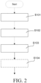
- the method of controlling a washer dryer to give steam care to laundry includes at least the following steps.
- Step I S 101 Cause a blowing device 3 to rotate at a first rotational speed to generate air flow in the circulating air duct 8, the air flow circulating in the circulating air duct 8 and the treatment tub 2.
- Step II S102 Turn on and control a heating device 1, heat air flow passing through the heating device 1, and cause an air temperature downstream of the heating device 1 to reach a first temperature.
- Step III S103 Turn on the water supply device 5, so that the water flow exchanges heat with the air flow heated by the heating device 1 and is at least partially evaporated into steam St.
- the steam St flows through the laundry in the drum 4 with the air flow, thereby producing care effects such as wrinkle removal, sterilization, and deodorization on the laundry.
- step III is followed by step IV S104 of causing the drum to rotate at a high speed.
- the drum 4 is caused to rotate at a first rotational speed, where the first rotational speed is greater than or equal to a minimum dehydration rotational speed.
- a preset dehydration rotational speed of a specific washer dryer 100 including the control step is between 800 revolutions per minute and 1200 revolutions per minute
- the first rotational speed in step IV is set to at least 800 revolutions per minute.
- the drum 4 may drive the air flow to flow when rotating at the foregoing rotational speed.
- the air flow between the drum 4 and the treatment tub 2 pushes the water at the bottom of the treatment tub 2 to form a water film on a surface of the treatment tub 2.
- the water film contacts the hot air and vaporizes to obtain the steam, which increases a way of generating steam and increases a steam concentration.
- a level of water supplied by the water supply device 5 and finally entering the treatment tub 2 is detected after the water supply device 5 is turned on, and the drum 4 is caused to rotate at the first rotational speed when the water level reaches a first predetermined water level L1.
- the first predetermined water level L1 is less than or equal to the water level of a water surface that exactly reaches an outer surface of the drum 4.
- the level of water supplied by the water supply device 5 and finally entering the treatment tub 2 may be detected in a direct manner.
- a sensor for sensing arrival of the water surface at a predetermined water level height position is arranged in the position on the tub wall of the treatment tub 2.
- the water level may be detected in an indirect manner.
- a pressure sensor is used to detect a water pressure in real time. The water pressure corresponds to a corresponding predetermined water level when reaching a predetermined magnitude.
- the first predetermined water level L1 is less than or equal to the water level of the water surface that exactly reaches the outer surface of the drum 4, the water does not wet the laundry in the drum 4.
- a preferred implementation is that the first predetermined water level L1 is set so that the water surface exactly touches the outer surface of the drum 4 or is very close to the outer surface of the drum 4. In this way, more water may be driven, and the water reaches a higher position on the surface of the treatment tub 2, thereby forming a water film with a larger area and providing a larger amount of steam.
- the drum 4 switches to rotate at a second rotational speed after rotating at the first rotational speed for a first predetermined duration.
- the second rotational speed is set to be less than the minimum dehydration rotational speed, and laundry may be rotated at the second rotational speed. It may be seen that the second rotational speed is less than a centrifugal rotational speed that causes the laundry to be attached to the drum, and the laundry may be rotated in the drum 4, so that all parts fully contact the steam, the laundry is looser as a whole, and wrinkles are reduced.
- the second rotational speed may be obtained in advance through experiments.
- the drum 4 is rotated in a single direction at the first rotational speed, and the drum 4 is rotated alternately in two directions at the second rotational speed.
- the alternate rotation may better prevent laundry entanglement, so that the laundry is fully rotated and shaken loose.
- the drum 4 may rotate only once at the first rotational speed, or the drum 4 may rotate alternately at the first rotational speed and the second rotational speed. If the drum 4 is rotated alternately at the first rotational speed and the second rotational speed, a duration of rotation at the first rotational speed is to be set shorter to reduce a possibility of wrinkles caused by centrifugal extrusion of the laundry against each other.
- An advantage of intermittently rotating the drum 4 at the first rotational speed is that the water film is generated on the wall of the treatment tub 2, and a new water film is continuously generated after the water film is evaporated, thereby continuously generating steam in this manner.
- the first temperature used in step II S102 is a highest safe temperature for fabrics.
- the temperature may be obtained by using a temperature sensor 9 arranged downstream of the heating device 1 in an air flow direction shown in FIG. 1 .
- the first temperature is set higher, so that a higher temperature is quickly obtained in a space where air flows, which improves evaporation efficiency.
- the heating device 1 is controlled to reduce the air temperature downstream of the heating device 1 to a second temperature. In this way, more care may be given to the laundry, and the laundry may be prevented from being damaged due to a long-term high temperature.
- a preferred embodiment further includes that after the water supply device 5 is turned on, the water supply device 5 is turned on and turned off at a preset frequency, and the blowing device 3 and the heating device 1 are kept on during turn-off of the water supply device 5.
- water may form a water film on a surface of the circulating air duct 8 and/or the treatment tub 2.
- circulating hot air may heat and evaporate the water film.
- the water supply device 5 is turned on again to generate a new water film. In this way, water may be saved to avoid a waste of water caused by continuous water supply from the water supply device 5.
- the water supply device 5 includes a first water supply device 51 with a great flow rate and a second water supply device 52 with a small flow rate. On this condition, only the first water supply device 51 is preferably turned on.
- the water level in the treatment tub 2 may rise, which may result in water entering the drum 4 to soak the laundry in the drum 4. Therefore, after the water supply device 5 is turned on, the water level in the treatment tub 2 is detected in real time.
- the water level reaches a second predetermined water level L2 the drainage device 6 is turned on to drain the water in the treatment tub 2.
- the second predetermined water level L2 is less than a level of water that exactly reaches the outer surface of the drum 4.
- the second predetermined water level L2 may be the same as the first predetermined water level L1.
- a manner in which the water exactly reaches the outer surface of the drum 4 is only to be used in a scenario where the drum 4 is rotated at the first rotational speed.
- the water surface is to be kept at a distance from the drum 4 to prevent the water from wetting the laundry in the drum 4.
- the drainage device 6 When the drainage device 6 is turned on for a third preset duration, or when it is detected that the water level of the treatment tub 2 is less than or equal to a third predetermined water level L3, the drainage device 6 is turned off.
- the third predetermined water level L3 is less than the first predetermined water level L1 and the second predetermined water level L2, and a relatively small parameter is to be selected.
- the water supply device 5 when the water level reaches the second predetermined water level L2, the water supply device 5 is turned off after the drainage device 6 is turned on or while the drainage device 6 is being turned on.
- the water level is less than or equal to the third predetermined water level L3, the water supply device 5 is turned on again.
- the blowing device 3 and the heating device 1 are kept on.
- the drainage device 6 is turned on and turned off at a predetermined frequency that prevents water from entering the drum 4, to drain the water in the treatment tub.
- the predetermined frequency may be determined in advance by calculating water supply of the water supply device 5 or by experiments.
- the foregoing process of generating the steam lasts for a set duration, or the duration of the foregoing process is adjusted based on a detected air humidity within the treatment tub 2 or the circulating air duct 8. Subsequently, in an embodiment, processes such as dehumidification, cooling, and maintenance are performed.
Landscapes
- Engineering & Computer Science (AREA)
- Textile Engineering (AREA)
- Control Of Washing Machine And Dryer (AREA)
Abstract
Description
- The present invention relates to the field of control methods of washer dryers, and also relates to a washer dryer.
- Research has found that steam has care effects such as wrinkle removal, sterilization, and deodorization on fabrics. Therefore, various laundry care machines apply the steam to a care program to provide specialized care for laundry.
- To generate steam, a common and easy-to-think approach is to introduce a steam generating device. For example, water in a specially arranged water container is heated, or water mists are generated by using an atomization device, and then the water mists are heated. As a result, this not only increases costs of a machine, but also takes up the already cramped space in the machine, which increases design difficulty and maintenance costs of the machine.
- An object of the present invention is to generate steam through a new control method by using existing hardware of a washer dryer, thereby giving steam care to laundry.
- Embodiments of the present invention disclose a method of controlling a washer dryer to give steam care to laundry. The washer dryer includes a circulating air duct with two ends in communication with a treatment tub. A heating device and a blowing device are arranged in the circulating air duct. A water supply device is configured to introduce water flow into the circulating air duct or along a tub wall of the treatment tub. A rotatable drum is arranged in the treatment tub, and a gap exists between the drum and the treatment tub. The control method includes the following steps:
- step I (S101): causing the blowing device to rotate at a first rotational speed to generate air flow in the circulating air duct, the air flow circulating in the circulating air duct and the treatment tub;
- step II (S 102): turning on and controlling the heating device, heating air flow passing through the heating device, and causing an air temperature downstream of the heating device to reach a first temperature; and
- step III (S103): turning on the water supply device, so that the water flow exchanges heat with the air flow heated by the heating device and is at least partially evaporated into steam.
- In an optional implementation, after the water supply device is turned on, the drum is caused to rotate at the first rotational speed, where the first rotational speed is greater than or equal to a minimum dehydration rotational speed.
- An optional implementation further includes that a level of water supplied by the water supply device and finally entering the treatment tub is detected after the water supply device is turned on, and the drum is caused to rotate at the first rotational speed when the water level reaches a first predetermined water level, where the first predetermined water level is less than or equal to a water level of a water surface that exactly reaches an outer surface of the drum.
- Preferably, the drum switches to rotate at a second rotational speed after rotating at the first rotational speed for a first predetermined duration, where the second rotational speed is set to be less than the minimum dehydration rotational speed, and laundry is rotatable at the second rotational speed.
- Preferably, the drum is rotated in a single direction at the first rotational speed, and the drum is rotated alternately in two directions at the second rotational speed.
- In an embodiment, the drum is rotated alternately at the first rotational speed and the second rotational speed.
- An optional implementation further includes that the first temperature is a highest safe temperature for fabrics.
- In addition, after the heating device is turned on for a predetermined time or a predetermined stage, the heating device is controlled to reduce the air temperature downstream of the heating device to a second temperature.
- An optional implementation further includes that after the water supply device is turned on, the water supply device is turned on and turned off at a preset frequency, and the blowing device and the heating device are kept on during turn-off of the water supply device.
- In some optional embodiments, the water supply device includes a first water supply device with a great flow rate and a second water supply device with a small flow rate. On this condition, only the first water supply device is preferably turned on.
- In an implementation of the water supply device, the circulating air duct includes a heat exchange region, and the water supply device is configured to spray water to a wall of the heat exchange region.
- With the water supply from the water supply device, the water level in the treatment tub may rise, which may result in water entering the drum to soak the laundry in the drum. Therefore, the water level in the treatment tub is detected after the water supply device is turned on, and a drainage device is turned on to drain the water in the treatment tub when the water level reaches a second predetermined water level, where the second predetermined water level is less than a level of water that exactly reaches an outer surface of the drum.
- When the drainage device is turned on for a third preset duration, or when it is detected that the water level of the treatment tub is less than or equal to a third predetermined water level, the drainage device is turned off.
- In an embodiment, the water supply device is turned off when the water level reaches the second predetermined water level, the water supply device is turned on again when the water level is less than or equal to the third predetermined water level, and the blowing device and the heating device are kept on before the water supply device is turned on again after being turned off.
- An optional implementation further includes that after the water supply device is turned on, a drainage device is turned on and turned off at a predetermined frequency that prevents water from entering the drum to drain the water in the treatment tub.
- In a case that technical conditions permit, the foregoing various embodiments may be arbitrarily combined in various manners.
- The present invention further provides a washer dryer, including a circulating air duct with two ends in communication with a treatment tub. A heating device and a blowing device are arranged in the circulating air duct. A water supply device is configured to introduce water flow into the circulating air duct. A rotatable drum is arranged in the treatment tub. A gap exists between the drum and the treatment tub. The washer dryer further includes a control device. The control device is arranged to control operation of the washer dryer according to the method of any one or any combination of the various embodiments described above.
- A user-selectable steam care program is preset in the control device, and after the steam care program is started. The control device is configured to control the operation of the washer dryer according to the method of at least any one or any combination of the various embodiments described above.
- According to the washer dryer and the control method thereof of the present invention, steam may be generated by using a basic configuration of a machine without adding a special steam generating device, and the steam care is given to the laundry. In addition, since hot air passing through the circulating air duct has a high flow speed, a great flow rate, concentrated heat, and a good effect on water evaporation, a large amount of steam may be generated per unit time, which has a good care effect on the laundry. However, the water flow introduced along the tub wall of the treatment tub has a large diffusion area and a large contact area with the hot air, and therefore the amount of steam generated per unit time is also large.
- Some specific embodiments of the present invention are illustrated below with reference to the accompanying drawings.
-
FIG. 1 is a schematic diagram of a washer dryer. -
FIG. 2 is a flowchart of at least part of steps of a method of controlling a washer dryer to give steam care to laundry. - As shown in
FIG. 1 , awasher dryer 100 includes atreatment tub 2 and a drum 4 rotatably arranged in thetreatment tub 2. A gap exists between the drum 4 and thetreatment tub 2. Fine through holes are provided on a drum wall of the drum 4, so that water and air may circulate between the drum 4 and thetreatment tub 2. A bottom of thetreatment tub 2 is in communication with adrainage device 6. Thedrainage device 6 includes adrainage pipeline 61 and adrainage pump 62 arranged on thedrainage pipe 61. - The
washer dryer 100 further includes asensor 7 for detecting parameters related to an amount of water in thetreatment tub 2. The parameters related to the amount of water may be water inflow, a water level, a water pressure, and the like. Thesensor 7 may be installed in various positions. In an embodiment shown inFIG. 1 , thesensor 7 is installed on the bottom of thetreatment tub 2. Specifically, a water pressure sensor may be used to obtain a relative height of the water level. In another implementation, a sensor for sensing a position of a horizontal plane may also be arranged in a position at a corresponding target water level on the tub wall of thetreatment tub 2. - The
washer dryer 100 further includes a circulatingair duct 8. Both ends of the circulatingair duct 8 are in communication with thetreatment tub 2. Aheating device 1 and a blowingdevice 3 are arranged in the circulatingair duct 8. In the embodiment shown inFIG. 1 , the circulatingair duct 8 includes aheat exchange region 81, and awater supply device 5 is configured to spray water to a wall of theheat exchange region 81. In the embodiment, thewater supply device 5 includes a firstwater supply device 51 and a secondwater supply device 52. The firstwater supply device 51 has a great flow rate and is configured to flush lint attached to theheat exchange region 81 and a region below the heat exchange region. The secondwater supply device 52 has a small unit flow rate. After the second water supply device is turned on, water may be provided for heat exchange with hot and humid air to dry laundry during drying. - In another embodiment, the
water supply device 5 may include only one water supply device. - In another embodiment, the
water supply device 5 may be located in another region and spray water to another part. For example, the water supply device may be located near theblowing device 3 to spray water to theblowing device 3, which may be configured to flush lint attached to theblowing device 3. For example, the water supply device may also be located near theheating device 1, or may be arranged along the tub wall of thetreatment tub 2 to introduce water flow along the tub wall of thetreatment tub 2, so as to provide, in a general drying program, water for heat exchange with the hot and humid air to dry the laundry. - The
washer dryer 100 further includes acontrol device 10. According to program settings, for example, theheating device 1, theblowing device 3, thewater supply device 5, and thedrainage pump 62 may be controlled, so as to give various care to the laundry, such as washing, drying, and steam care. - A user-selectable steam care program is preset in the
control device 10. After the steam care program is started, the control device controls thewasher dryer 100 to operate and apply steam St to the laundry in the drum 4, so as to achieve effects such as wrinkle removal, sterilization, and deodorization on the laundry. The steam care program may be independently run to give care to dry laundry placed in the drum 4, or may be run after another program such as a drying program, to achieve a better effect of wrinkle removal on the laundry or reduce a large number of wrinkles caused by the dried laundry that have not been taken out for a long time. - The following is a detailed description of the method of controlling a washer dryer to give steam care. However, various embodiments described below cannot exhaust all embodiments within a technical concept of the present invention.
- As shown in
FIG. 2 , the method of controlling a washer dryer to give steam care to laundry includes at least the following steps. - Step I S 101: Cause a
blowing device 3 to rotate at a first rotational speed to generate air flow in the circulatingair duct 8, the air flow circulating in the circulatingair duct 8 and thetreatment tub 2. - Step II S102: Turn on and control a
heating device 1, heat air flow passing through theheating device 1, and cause an air temperature downstream of theheating device 1 to reach a first temperature. - Step III S103: Turn on the
water supply device 5, so that the water flow exchanges heat with the air flow heated by theheating device 1 and is at least partially evaporated into steam St. - The steam St flows through the laundry in the drum 4 with the air flow, thereby producing care effects such as wrinkle removal, sterilization, and deodorization on the laundry.
- In an optional embodiment, step III is followed by step IV S104 of causing the drum to rotate at a high speed. In the step, the drum 4 is caused to rotate at a first rotational speed, where the first rotational speed is greater than or equal to a minimum dehydration rotational speed. For example, if a preset dehydration rotational speed of a
specific washer dryer 100 including the control step is between 800 revolutions per minute and 1200 revolutions per minute, the first rotational speed in step IV is set to at least 800 revolutions per minute. - Water supplied by the
water supply device 5 to the circulatingair duct 8 or thetreatment tub 2 eventually reaches a bottom of thetreatment tub 2. Therefore, the drum 4 may drive the air flow to flow when rotating at the foregoing rotational speed. Particularly, the air flow between the drum 4 and thetreatment tub 2 pushes the water at the bottom of thetreatment tub 2 to form a water film on a surface of thetreatment tub 2. The water film contacts the hot air and vaporizes to obtain the steam, which increases a way of generating steam and increases a steam concentration. - A level of water supplied by the
water supply device 5 and finally entering thetreatment tub 2 is detected after thewater supply device 5 is turned on, and the drum 4 is caused to rotate at the first rotational speed when the water level reaches a first predetermined water level L1. The first predetermined water level L1 is less than or equal to the water level of a water surface that exactly reaches an outer surface of the drum 4. - The level of water supplied by the
water supply device 5 and finally entering thetreatment tub 2 may be detected in a direct manner. For example, a sensor for sensing arrival of the water surface at a predetermined water level height position is arranged in the position on the tub wall of thetreatment tub 2. Alternatively, the water level may be detected in an indirect manner. For example, a pressure sensor is used to detect a water pressure in real time. The water pressure corresponds to a corresponding predetermined water level when reaching a predetermined magnitude. The water levels mentioned below are all applicable to the implementation described in this paragraph. - If the first predetermined water level L1 is less than or equal to the water level of the water surface that exactly reaches the outer surface of the drum 4, the water does not wet the laundry in the drum 4. In addition, a preferred implementation is that the first predetermined water level L1 is set so that the water surface exactly touches the outer surface of the drum 4 or is very close to the outer surface of the drum 4. In this way, more water may be driven, and the water reaches a higher position on the surface of the
treatment tub 2, thereby forming a water film with a larger area and providing a larger amount of steam. - To avoid new wrinkles caused by laundry squeezing each other as a result of long-term rotation of the drum 4 at the dehydration rotational speed, the drum 4 switches to rotate at a second rotational speed after rotating at the first rotational speed for a first predetermined duration. The second rotational speed is set to be less than the minimum dehydration rotational speed, and laundry may be rotated at the second rotational speed. It may be seen that the second rotational speed is less than a centrifugal rotational speed that causes the laundry to be attached to the drum, and the laundry may be rotated in the drum 4, so that all parts fully contact the steam, the laundry is looser as a whole, and wrinkles are reduced. The second rotational speed may be obtained in advance through experiments.
- The drum 4 is rotated in a single direction at the first rotational speed, and the drum 4 is rotated alternately in two directions at the second rotational speed. The alternate rotation may better prevent laundry entanglement, so that the laundry is fully rotated and shaken loose.
- The drum 4 may rotate only once at the first rotational speed, or the drum 4 may rotate alternately at the first rotational speed and the second rotational speed. If the drum 4 is rotated alternately at the first rotational speed and the second rotational speed, a duration of rotation at the first rotational speed is to be set shorter to reduce a possibility of wrinkles caused by centrifugal extrusion of the laundry against each other. An advantage of intermittently rotating the drum 4 at the first rotational speed is that the water film is generated on the wall of the
treatment tub 2, and a new water film is continuously generated after the water film is evaporated, thereby continuously generating steam in this manner. - The first temperature used in step II S102 is a highest safe temperature for fabrics. The temperature may be obtained by using a
temperature sensor 9 arranged downstream of theheating device 1 in an air flow direction shown inFIG. 1 . The first temperature is set higher, so that a higher temperature is quickly obtained in a space where air flows, which improves evaporation efficiency. - In addition, after the
heating device 1 is turned on for a predetermined time or a predetermined stage, theheating device 1 is controlled to reduce the air temperature downstream of theheating device 1 to a second temperature. In this way, more care may be given to the laundry, and the laundry may be prevented from being damaged due to a long-term high temperature. - A preferred embodiment further includes that after the
water supply device 5 is turned on, thewater supply device 5 is turned on and turned off at a preset frequency, and theblowing device 3 and theheating device 1 are kept on during turn-off of thewater supply device 5. After thewater supply device 5 is turned on, water may form a water film on a surface of the circulatingair duct 8 and/or thetreatment tub 2. After thewater supply device 5 is turned off, circulating hot air may heat and evaporate the water film. After the water film is evaporated, thewater supply device 5 is turned on again to generate a new water film. In this way, water may be saved to avoid a waste of water caused by continuous water supply from thewater supply device 5. - When the
water supply device 5 includes a firstwater supply device 51 with a great flow rate and a secondwater supply device 52 with a small flow rate. On this condition, only the firstwater supply device 51 is preferably turned on. - With the water supply from the
water supply device 5, the water level in thetreatment tub 2 may rise, which may result in water entering the drum 4 to soak the laundry in the drum 4. Therefore, after thewater supply device 5 is turned on, the water level in thetreatment tub 2 is detected in real time. When the water level reaches a second predetermined water level L2, thedrainage device 6 is turned on to drain the water in thetreatment tub 2. The second predetermined water level L2 is less than a level of water that exactly reaches the outer surface of the drum 4. For the control method including step IV S104, the second predetermined water level L2 may be the same as the first predetermined water level L1. Moreover, a manner in which the water exactly reaches the outer surface of the drum 4 is only to be used in a scenario where the drum 4 is rotated at the first rotational speed. In another scenario, the water surface is to be kept at a distance from the drum 4 to prevent the water from wetting the laundry in the drum 4. - When the
drainage device 6 is turned on for a third preset duration, or when it is detected that the water level of thetreatment tub 2 is less than or equal to a third predetermined water level L3, thedrainage device 6 is turned off. The third predetermined water level L3 is less than the first predetermined water level L1 and the second predetermined water level L2, and a relatively small parameter is to be selected. - In an embodiment, when the water level reaches the second predetermined water level L2, the
water supply device 5 is turned off after thedrainage device 6 is turned on or while thedrainage device 6 is being turned on. When the water level is less than or equal to the third predetermined water level L3, thewater supply device 5 is turned on again. In addition, before thewater supply device 5 is turned on again after being turned off, theblowing device 3 and theheating device 1 are kept on. - In another optional implementation, it is not determined based on the water level whether the
drainage device 6 is turned on, but after thewater supply device 5 is turned on, thedrainage device 6 is turned on and turned off at a predetermined frequency that prevents water from entering the drum 4, to drain the water in the treatment tub. The predetermined frequency may be determined in advance by calculating water supply of thewater supply device 5 or by experiments. - In a steam care program, the foregoing process of generating the steam lasts for a set duration, or the duration of the foregoing process is adjusted based on a detected air humidity within the
treatment tub 2 or the circulatingair duct 8. Subsequently, in an embodiment, processes such as dehumidification, cooling, and maintenance are performed. - Various specific implementations described above and shown in the accompanying drawings are merely used for describing the present invention. Within the scope of the basic technical idea of the present invention, any form of changes made to the present invention by a person of ordinary skill in the related art fall within the protection scope of the present invention.
Claims (17)
- A method of controlling a washer dryer (100) to give steam care to laundry, wherein the washer dryer (100) comprises a circulating air duct (8) with both ends in communication with a treatment tub (2), a heating device (1) and a blowing device (3) are arranged in the circulating air duct, a water supply device (5) is configured to introduce water flow into the circulating air duct or along a tub wall of the treatment tub, a rotatable drum (4) is arranged in the treatment tub, and a gap exists between the drum and the treatment tub, characterized in that the control method comprises the following steps:step I (S101): causing the blowing device to rotate at a first rotational speed to generate air flow in the circulating air duct, the air flow circulating in the circulating air duct and the treatment tub;step II (S102): turning on and controlling the heating device, heating air flow passing through the heating device, and causing an air temperature downstream of the heating device to reach a first temperature; andstep III (S103): turning on the water supply device, so that the water flow exchanges heat with the air flow heated by the heating device and is at least partially evaporated into steam.
- The control method according to claim 1, characterized in that after the water supply device is turned on, the drum is caused to rotate at the first rotational speed, wherein the first rotational speed is greater than or equal to a minimum dehydration rotational speed.
- The control method according to claim 2, characterized in that a level of water supplied by the water supply device and finally entering the treatment tub is detected after the water supply device is turned on, and the drum is caused to rotate at the first rotational speed when the water level reaches a first predetermined water level, wherein the first predetermined water level is less than or equal to a water level of a water surface that exactly reaches an outer surface of the drum.
- The control method according to claim 2, characterized in that the drum switches to rotate at a second rotational speed after rotating at the first rotational speed for a first predetermined duration, wherein the second rotational speed is set to be less than the minimum dehydration rotational speed, and laundry is rotatable at the second rotational speed.
- The control method according to claim 4, characterized in that the drum is rotated in a single direction at the first rotational speed, and the drum is rotated alternately in two directions at the second rotational speed.
- The control method according to claim 4, characterized in that the drum is rotated alternately at the first rotational speed and the second rotational speed.
- The control method according to claim 1, characterized in that the first temperature is a highest safe temperature for fabrics.
- The control method according to claim 7, characterized in that after the heating device is turned on for a predetermined time or a predetermined stage, the heating device is controlled to reduce the air temperature downstream of the heating device to a second temperature.
- The control method according to claim 1, characterized in that after the water supply device is turned on, the water supply device is turned on and turned off at a preset frequency, and the blowing device and the heating device are kept on during turn-off of the water supply device.
- The control method according to claim 1, characterized in that the water supply device comprises a first water supply device with a great flow rate and a second water supply device with a small flow rate, wherein only the first water supply device is turned on.
- The control method according to claim 1, characterized in that the circulating air duct comprises a heat exchange region, and the water supply device is configured to spray water to a wall of the heat exchange region.
- The control method according to claim 1, characterized in that the water level in the treatment tub is detected after the water supply device is turned on, and a drainage device is turned on to drain the water in the treatment tub when the water level reaches a second predetermined water level, wherein the second predetermined water level is less than a level of water that exactly reaches an outer surface of the drum.
- The control method according to claim 12, characterized in that when the drainage device is turned on for a third preset duration, or when it is detected that the water level of the treatment tub is less than or equal to a third predetermined water level, the drainage device is turned off.
- The control method according to claim 13, characterized in that the water supply device is turned off when the water level reaches the second predetermined water level, the water supply device is turned on again when the water level is less than or equal to the third predetermined water level, and the blowing device and the heating device are kept on before the water supply device is turned on again after being turned off.
- The control method according to claim 1, characterized in that after the water supply device is turned on, a drainage device is turned on and turned off at a predetermined frequency that prevents water from entering the drum to drain the water in the treatment tub.
- A washer dryer, characterized by comprising a circulating air duct (8) with two ends in communication with a treatment tub (2), wherein a heating device (1) and a blowing device (3) are arranged in the circulating air duct, a water supply device (5) is configured to introduce water flow into the circulating air duct, a rotatable drum (4) is arranged in the treatment tub, and a gap exists between the drum and the treatment tub, and characterized by further comprising a control device (10), wherein the control device is arranged to control operation of a washer dryer according to the method of any of claims 1 to 15.
- The washer dryer according to claim 16, characterized in that a user-selectable steam care program is preset in the control device, and after the steam care program is started, the control device controls the operation of the washer dryer according to at least one of claims 1 to 14.
Applications Claiming Priority (1)
| Application Number | Priority Date | Filing Date | Title |
|---|---|---|---|
| CN202310624303.XA CN119083116A (en) | 2023-05-30 | 2023-05-30 | Washing and drying machine and control method for steam care of clothes |
Publications (1)
| Publication Number | Publication Date |
|---|---|
| EP4471202A1 true EP4471202A1 (en) | 2024-12-04 |
Family
ID=91030022
Family Applications (1)
| Application Number | Title | Priority Date | Filing Date |
|---|---|---|---|
| EP24174526.4A Pending EP4471202A1 (en) | 2023-05-30 | 2024-05-07 | A washer dryer and method of controlling the washer dryer to give steam care to the laundry |
Country Status (2)
| Country | Link |
|---|---|
| EP (1) | EP4471202A1 (en) |
| CN (1) | CN119083116A (en) |
Citations (3)
| Publication number | Priority date | Publication date | Assignee | Title |
|---|---|---|---|---|
| WO2007024056A1 (en) * | 2005-08-25 | 2007-03-01 | Lg Electronics Inc. | A laundry machine and a method for operating the same |
| US20130198970A1 (en) * | 2012-02-06 | 2013-08-08 | Youngjin DOH | Control method of laundry machine |
| CN113605037A (en) * | 2020-10-26 | 2021-11-05 | 松下家电(中国)有限公司 | Control method of clothes care equipment |
-
2023
- 2023-05-30 CN CN202310624303.XA patent/CN119083116A/en active Pending
-
2024
- 2024-05-07 EP EP24174526.4A patent/EP4471202A1/en active Pending
Patent Citations (3)
| Publication number | Priority date | Publication date | Assignee | Title |
|---|---|---|---|---|
| WO2007024056A1 (en) * | 2005-08-25 | 2007-03-01 | Lg Electronics Inc. | A laundry machine and a method for operating the same |
| US20130198970A1 (en) * | 2012-02-06 | 2013-08-08 | Youngjin DOH | Control method of laundry machine |
| CN113605037A (en) * | 2020-10-26 | 2021-11-05 | 松下家电(中国)有限公司 | Control method of clothes care equipment |
Also Published As
| Publication number | Publication date |
|---|---|
| CN119083116A (en) | 2024-12-06 |
Similar Documents
| Publication | Publication Date | Title |
|---|---|---|
| JP6530169B2 (en) | Clothing processing equipment | |
| US8166669B2 (en) | Laundry machine and a method for operating the same | |
| JP4163445B2 (en) | Washing and drying machine | |
| KR101020417B1 (en) | How to control the fragrance of the dryer | |
| JP5044482B2 (en) | Washing and drying machine | |
| KR20060061974A (en) | Wrinkle removal apparatus of clothing and method | |
| JP4987618B2 (en) | Washing and drying machine | |
| KR100867122B1 (en) | Washing machine and control method | |
| KR20050099285A (en) | Heating apparatus of washing machine and washing method | |
| JP5319801B2 (en) | Washing and drying machine | |
| JP4987619B2 (en) | Washing and drying machine | |
| KR101560386B1 (en) | Laundry Treating Apparatus | |
| JP2024096459A (en) | washing machine | |
| JP6702699B2 (en) | Washing machine | |
| JP5300946B2 (en) | Drum washing machine | |
| JP2015057156A (en) | Washing machine | |
| CN110735278B (en) | Vertical washing and drying machine | |
| CN119083116A (en) | Washing and drying machine and control method for steam care of clothes | |
| JP5296170B2 (en) | Drum washing machine | |
| JP2010011924A (en) | Washing/drying machine | |
| KR100659309B1 (en) | Control method of washing machine with steam generator | |
| JP2024147252A (en) | Clothes Processing Equipment | |
| KR101560387B1 (en) | Laundry Treating Apparatus | |
| EP3853404B1 (en) | A laundry dryer | |
| JPH04242692A (en) | Drum type washing and drying machine |
Legal Events
| Date | Code | Title | Description |
|---|---|---|---|
| PUAI | Public reference made under article 153(3) epc to a published international application that has entered the european phase |
Free format text: ORIGINAL CODE: 0009012 |
|
| STAA | Information on the status of an ep patent application or granted ep patent |
Free format text: STATUS: THE APPLICATION HAS BEEN PUBLISHED |
|
| AK | Designated contracting states |
Kind code of ref document: A1 Designated state(s): AL AT BE BG CH CY CZ DE DK EE ES FI FR GB GR HR HU IE IS IT LI LT LU LV MC ME MK MT NL NO PL PT RO RS SE SI SK SM TR |
|
| STAA | Information on the status of an ep patent application or granted ep patent |
Free format text: STATUS: REQUEST FOR EXAMINATION WAS MADE |
|
| 17P | Request for examination filed |
Effective date: 20250604 |
|
| STAA | Information on the status of an ep patent application or granted ep patent |
Free format text: STATUS: EXAMINATION IS IN PROGRESS |
|
| 17Q | First examination report despatched |
Effective date: 20251118 |