EP4471200A1 - Image recording device for loom - Google Patents
Image recording device for loom Download PDFInfo
- Publication number
- EP4471200A1 EP4471200A1 EP23743376.8A EP23743376A EP4471200A1 EP 4471200 A1 EP4471200 A1 EP 4471200A1 EP 23743376 A EP23743376 A EP 23743376A EP 4471200 A1 EP4471200 A1 EP 4471200A1
- Authority
- EP
- European Patent Office
- Prior art keywords
- image
- unit
- loom
- capturing
- storage unit
- Prior art date
- Legal status (The legal status is an assumption and is not a legal conclusion. Google has not performed a legal analysis and makes no representation as to the accuracy of the status listed.)
- Pending
Links
Images
Classifications
-
- D—TEXTILES; PAPER
- D03—WEAVING
- D03D—WOVEN FABRICS; METHODS OF WEAVING; LOOMS
- D03D47/00—Looms in which bulk supply of weft does not pass through shed, e.g. shuttleless looms, gripper shuttle looms, dummy shuttle looms
- D03D47/28—Looms in which bulk supply of weft does not pass through shed, e.g. shuttleless looms, gripper shuttle looms, dummy shuttle looms wherein the weft itself is projected into the shed
- D03D47/30—Looms in which bulk supply of weft does not pass through shed, e.g. shuttleless looms, gripper shuttle looms, dummy shuttle looms wherein the weft itself is projected into the shed by gas jet
- D03D47/3066—Control or handling of the weft at or after arrival
- D03D47/3073—Detection means therefor
-
- D—TEXTILES; PAPER
- D03—WEAVING
- D03D—WOVEN FABRICS; METHODS OF WEAVING; LOOMS
- D03D47/00—Looms in which bulk supply of weft does not pass through shed, e.g. shuttleless looms, gripper shuttle looms, dummy shuttle looms
- D03D47/28—Looms in which bulk supply of weft does not pass through shed, e.g. shuttleless looms, gripper shuttle looms, dummy shuttle looms wherein the weft itself is projected into the shed
- D03D47/30—Looms in which bulk supply of weft does not pass through shed, e.g. shuttleless looms, gripper shuttle looms, dummy shuttle looms wherein the weft itself is projected into the shed by gas jet
- D03D47/3093—Displaying data
Definitions
- the present invention relates to an image recording device for a loom.
- a loom is configured to store a weft yarn from a yarn supply member in a weft yarn measuring and storing member, to start weft insertion by releasing the stored weft yarn with a main nozzle, to transport the weft yarn inserted in a weaving width with a sub-nozzle, and to end the weft insertion.
- a weft yarn brake is used to apply braking to the weft yarn near the completion of the weft insertion.
- Patent Document 2 Furthermore, a technique of a camera-equipped stroboscope for recording the travel state of the weft yarn is proposed in Patent Document 2.
- the present disclosure which has been made in view of the above problems, is directed to providing an image recording device for a loom that is capable of providing an image showing a weft yarn travel state necessary to reliably classify the type of a weft insertion abnormality with a simple configuration when the weft insertion abnormality occurs.
- An image recording device for a loom includes: an image capture unit configured to capture an image of a weft yarn while the weft yarn travels; a storage unit configured to store the image generated by capturing the image by the image capture unit; a record unit configured to record the image read from the storage unit; and a control unit configured to control capturing the image by the image capture unit, and inputting and outputting the image to and from the storage unit and the record unit, wherein the control unit includes a trigger controller that generates a trigger signal based on an operation signal output according to an operation of the loom, and controls a timing of capturing the image by the image capture unit with the trigger signal, an image controller that causes the storage unit to store the image generated by capturing the image by the image capture unit, and reads the image stored in the storage unit to record in the record unit, and a timer that measures an elapsed time from one of reception of the operation signal by the trigger controller, capturing of the image by the image capture unit, or storing of the image in the storage unit by
- the predetermined period of time is desirably determined according to the rotation speed of the machine base included in the loom.
- the image controller desirably adds time information at a time of capturing the image or time information at a time of storing the image to the image generated by capturing the image by the image capture unit, and stores the image to which the time information is added in the storage unit.
- the image capture unit desirably includes a light emitting unit and a camera, and executes emission of strobe flashes of light by the light emitting unit and capturing of the image while the weft yarn travels by the camera, based on the trigger signal.
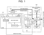
- FIG. 1 is a block diagram illustrating the configuration of the image recording device 100 together with a configuration of the loom 10 according to the first embodiment.
- the image recording device 100 illustrated in FIG. 1 is configured to capture, store, and record images of the weft yarn Y while the weft yarn Y travels in the loom 10, and includes a control unit 110, an image capture unit 120, an operation unit 130, a storage unit 140, and a record unit 150 as main components.
- control unit 110 includes a trigger controller 111, an image controller 112, and a timer 113.
- the trigger controller 111 generates a trigger signal based on an operation signal output according to an operation of the loom 10 and a timing adjustment value input from the operation unit 130, and controls a timing of capturing an image by the image capture unit 120.
- the image controller 112 performs a control in such a manner that the images generated by capturing the images by the image capture unit 120 are stored in the storage unit 140, and that the images stored in the storage unit 140 are read out and recorded in the record unit 150 under certain conditions.
- the image controller 112 may add time information at the time of capturing or storing the images. That is, the image controller 112 controls input and output of the images to and from the storage unit 140 and the record unit 150.
- the timer 113 measures an elapsed time from one of reception of an operation signal by the trigger controller 111, capturing of the images by the image capture unit 120, or storing of the images in the storage unit 140 by the image controller 112.
- the trigger controller 111, the image capture unit 120, and the operation unit 130 cooperate to form a camera-equipped stroboscope SS in which a stroboscope and a camera are combined in order to visually check a travel state of the weft yarn Y in the loom 10.
- the image capture unit 120 includes a light emitting unit 121 and a camera 122.
- the light emitting unit 121 includes a xenon lamp or a light emitting diode.
- the light emitting unit 121 receives a trigger signal from the trigger controller 111, and also receives electric power for emitting strobe flashes of light from an electric power source (not illustrated).
- the light emitting unit 121 emits strobe flashes of light to a capturing range in the loom 10 in accordance with a timing of a trigger signal from the trigger controller 111.
- the camera 122 receives a trigger signal from the trigger controller 111 and electric power for capturing images from the image controller 112.
- the camera 122 captures images of the weft yarn Y while the weft yarn Y travels in the capturing range in the loom 10 in accordance with the timing of the trigger signal from the trigger controller 111 in synchronization with the strobe flashes of light emitted by the light emitting unit 121, and supplies the images generated by the capturing to the image controller 112. In this way, a clear image showing the travel state of the weft yarn Y, which is necessary for reliably classifying the type of weft insertion abnormality, can be obtained.
- the timing adjustment value for adjusting a light emission timing of the light emitting unit 121 is input to the operation unit 130.
- the operation unit 130 transmits the input timing adjustment value to the trigger controller 111.
- the storage unit 140 temporarily stores the images generated by the capturing of the images by the image capture unit 120 under the control by the image controller 112.
- the storage unit 140 is configured to have at least a certain storage capacity corresponding to a fixed number of the images to be recorded in the record unit 150 for analyzing the weft insertion abnormality.
- the storage unit 140 may be a ring buffer that always stores a fixed number of the images captured most recently.
- the storage unit 140 may be configured to have a storage capacity larger than the fixed number of the images to be recorded in the record unit 150 .
- the record unit 150 records the fixed number of the images read from the storage unit 140 as a file that can be output to the outside.
- Storing of the images in the storage unit 140 and recording of the images in the recording device are controlled as follows.
- the image controller 112 refers to the elapsed time measured by the timer 113, and performs a control in such a manner that the images stored in the storage unit 140 are read out and recorded in the record unit 150 when any of a case in which the trigger controller 111 does not receive an operation signal before a predetermined period of time elapses, a case in which the capturing of the images by the image capture unit 120 stops and the image controller 112 does not receive the images from the image capture unit 120 before the predetermined period of time elapses, or a case in which the image controller 112 does not store the images in the storage unit 140 before the predetermined period of time elapses occurs.
- the above-mentioned predetermined period of time that serves as a reference for reading the images stored in the storage unit 140 and recording them in the record unit 150 may be a fixed period of time, or may be a variable time such as n times a rotation time calculated from a rotation speed of the machine base 17, which will be described later.
- the image controller 112 may determine the above-mentioned predetermined period of time by multiplying an interval between operation signals by n.
- the loom 10 includes a control 11, a yarn supply member 12, a weft yarn measuring and storing member 13, a weft insertion nozzle 14, a weft yarn travel passage 15, a travel sensor 16, a machine base 17, and an encoder 18, as main components. It is noted that only main components of the loom 10 related to the image recording device 100 are described.
- the controller 11 executes various controls of the loom 10.
- the yarn supply member 12 is provided on an upstream side of the weft yarn measuring and storing member 13 and stores the weft yarn Y.
- the weft yarn Y of the yarn supply member 12 is drawn out by the weft yarn measuring and storing member 13.
- the weft insertion nozzle 14 includes a tandem nozzle 14a and a main nozzle 14b. Compressed air discharged from the tandem nozzle 14a draws out the weft yarn Y in the weft yarn measuring and storing member 13. Compressed air discharged from the main nozzle 14b inserts the weft yarn Y into the weft yarn travel passage 15.
- a weft insertion brake configured to apply braking to the weft yarn Y travelling before the weft insertion is completed is provided on an upstream side of the tandem nozzle 14a.
- the weft insertion brake applies braking to the weft yarn Y, which is travelling at a high speed, to reduce the travelling speed of the weft yarn Y, thereby mitigating the impact of the weft yarn Y at a timing of completing the weft insertion.
- the weft yarn travel passage 15 is disposed on a downstream side of the weft insertion nozzle 14 and includes a plurality of dents.
- the plurality of dents (not illustrated), sub-nozzles (not illustrated), and the travel sensor 16 are disposed in the weft yarn travel passage 15.
- the travel sensor 16 includes an in-weaving width sensor 16a, and an end sensor 16b.
- the in-weaving width sensor 16a is disposed on an upstream side of the end sensor 16b and on a downstream side of the center of the weaving width in the weft yarn travel passage 15.
- the end sensor 16b is disposed on a downstream side of the weft yarn travel passage 15 and on a downstream side of the weaving width.
- the machine base 17 performs weaving according to the specifications of fabric, and rotates at a predetermined number of revolutions based on instructions from the controller 11.
- the encoder 18 outputs an operation signal corresponding to rotation of the machine base 17, that is, the operation of the loom, to the image recording device 100.
- the controller 11 determines a travel abnormality of the weft yarn Y, i.e., a weft insertion abnormality, when the weft travel sensor 16 detects an abnormality such as delay or arrival failure of the weft yarn Y.
- a weft insertion abnormality the controller 11 stops rotation of the machine base 17, thereby stopping the operation of the loom 10.
- an operation signal from the encoder 18 also stops.
- the image capture unit 120 captures the images of the weft yarn Y while the weft yarn Y travels with an area from the weft insertion brake on the upstream side of the tandem nozzle 14a, through the weft yarn travel passage 15, to the end sensor 16b on the downstream side of the weft yarn travel passage 15 and on the downstream side of the weaving width, as an image capture range.
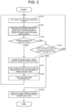
- FIG. 2 is a flowchart showing a procedure of capturing, storing, and recording images by the image recording device 100 according to the first embodiment.
- Step S101 the trigger controller 111 is on standby for receiving an operation signal from the loom 10. Then, the process proceeds to Step S102.
- Step S102 the timer 113 measures an elapsed time from one of reception of the operation signal by the trigger controller 111, reception of the captured image from the image capture unit 120 by the image controller 112, or storing of the image in the storage unit 140 under the control of the image controller 112, which has occurred most recently. Then, the process proceeds to Step S103.
- Step S103 the control unit 110 checks whether an operation signal has been received, and proceeds to Step S104 if the operation signal has been received. At this time, it is sufficient to check whether the trigger controller 111 in the control unit 110 has received an operation signal.
- Step S104 the trigger controller 111 generates a trigger signal based on the operation signal from the loom 10 and the timing adjustment value from the operation unit 130.
- the trigger controller 111 supplies the generated trigger signal to the light emitting unit 121 and the camera 122 of the image capture unit 120. Then, the process proceeds to Step S105.
- Step S105 the light emitting unit 121 emits strobe flashes of light in the capturing range of the loom 10 in accordance with the timing of the trigger signal from the trigger controller 111.
- the camera 122 captures the images of the weft yarn Y while the weft yarn Y travels in the capturing range in the loom 10 in accordance with the timing of the trigger signal from the trigger controller 111, and supplies the images generated by the capturing to the image controller 112. Then, the process proceeds to Step S106.
- Step S106 the image controller 112 stores the images generated by capturing the images by the image capture unit 120 in the storage unit 140. If the storage unit 140 has sufficient storage capacity, the image controller 112 stores new images in addition to the previous images. Furthermore, when the storage capacity of the storage unit 140 is a fixed limited capacity, the image controller 112 stores the newest images in the storage unit 140 so as to overwrite the oldest images stored in the storage unit 140. In other words, the storing of the images in the storage unit 140 is temporary keeping of the images. Then, the process returns to Step S101.
- Step S103 determines in Step S103 that an operation signal has not been received from the loom 10.
- Step S107 the control unit 110 checks whether any of the reception of the operation signal from the loom 10 before the predetermined period of time elapses, capturing of the images by the image capture unit 120 before the predetermined period of time elapses, or storing of the images in the storage unit 140 before the predetermined period of time elapses has occurred.
- the image controller 112 determines whether or not the elapsed time counted by the timer 113, which has started measurement in Step S102, exceeds a predetermined period of time.
- Step S107 If the control unit 110 checks in Step S107 that one of reception of the operation signal, capturing of the images, or storing of the captured images has been performed before the predetermined period of time elapses, the process returns to Step S101.
- Step S107 if the control unit 110 checks in Step S107 that none of reception of the operation signal before the predetermined period of time elapses, capturing of the images by the image capture unit 120 before the predetermined period of time elapses, or storing of the images in the storage unit 140 before the predetermined period of time elapses occurs, the process proceeds to Step S108.
- the control unit 110 may be configured to perform the checking in Step S107 based only on whether the operation signal is received before the predetermined period of time elapses/whether the operation signal is not received for the predetermined period of time or longer.
- Step S108 the control unit 110 performs a control so that a fixed number of the images captured most recently, of the images stored in storage unit 140, are recorded in record unit 150 as files.
- the fixed number of the images recorded in the record unit 150 means the images captured during a certain period of time immediately before the machine base 17 of the loom 10 stops.
- the recording of the images in the record unit 150 corresponds to saving of the images as files that can be output to the outside.
- the images recorded in the record unit 150 are output to the outside as the files under the control of the image controller 112 or in response to a request from the outside.
- the fixed number of the images recorded in the record unit 150 are the images necessary for checking that the travel state of the weft yarn Y gradually deteriorates until a weft insertion abnormality occurs, and corresponds to, for example, the images for about 30 picks of the weft yarn Y.
- the operator can identify circumstances and locations of a weft insertion abnormality, such as clogging or tangling of the weft yarn Y near an outlet of the nozzle, or a problem in introducing the weft yarn Y into a stretch pipe installed near the reed.
- a weft insertion abnormality such as clogging or tangling of the weft yarn Y near an outlet of the nozzle, or a problem in introducing the weft yarn Y into a stretch pipe installed near the reed.
- the image recording device 100 of the first embodiment it is possible to use the image recording device 100 of the first embodiment to reliably classify the type of a weft insertion abnormality, which cannot be accurately classified when the detection result of the conventional travel sensor 16 is used.
- the signal transmitted between the loom 10 and the image recording device 100 is only an operation signal from the loom 10, which is also used in the conventional camera-equipped stroboscope. Therefore, the loom 10 requires no modification. That is, there is no need to transmit the detection result of the weft insertion abnormality in the loom 10 to the image recording device 100, so that the configuration can be simplified.
- the image capture unit 120 includes the light emitting unit 121 that emits strobe flashes of light and the camera 122 that captures images in synchronization with the strobe flashes of light.
- the light emitting unit 121 may be omitted.
- the trigger controller 111, the image controller 112, and the timer 113 forming the control unit 110 do not have to be in the same or adjacent positions or conditions, but may be located at separate positions.
- the image recording device 100 of the first embodiment can be configured by connecting the image controller 112 and the storage unit 140 to the portable camera-equipped stroboscope SS including the trigger controller 111, the image capture unit 120, and the operation unit 130.
- the image recording device 100 since the signal wiring connection with the loom 10 is only for the operation signal, the loom 10 does not have to be modified, and the image recording device 100 may be configured simply.
- the storage unit 140 and the record unit 150 do not have to be physically connected to the image controller 112, and for example, a storage of an external server may be used.
- the trigger controller 111, the image controller 112, and the timer 113 included in the control unit 110 may be independent circuits or devices, or implemented in a single processor.
- the units of the image recording device 100 may receive electric power from a service outlet of the loom 10 or the like.
- the image controller 112 may add time information at the time of capturing or storing the images as a timestamp. In this case, the image controller 112 can distinguish a normal stop due to the end of operation of the loom 10 from a stop due to the weft insertion abnormalities by comparing the latest timestamp added to the images stored in the storage unit 140 with the time of the end of the operation of the loom 10. Furthermore, the image controller 112 can easily check whether images has been captured or stored in Step S107 by comparing the latest timestamp added to the images stored in storage unit 140 with the current time.
- control unit 110 may optimize the checking process efficiently by appropriately changing the predetermined period of time used for the checking in Step S107 in accordance with the change in the interval between the operation signals.
- the image recording device 100 includes: the image capture unit 120 configured to capture an image of the weft yarn Y while the weft yarn Y travels; the storage unit 140 configured to store the image generated by capturing the image; and the control unit 110 configured to control capturing, storing, and recording of the image, the control unit 110 including a trigger controller 111 that generates a trigger signal based on an operation signal generated in accordance with an operation of the loom 10, an image controller 112 that causes the storage unit 140 to store the image generated by capturing the image by the image capture unit 120, and reads out the image stored in the storage unit 140 and records it in the record unit 150, and a timer 113 that measures an elapsed time from one of reception of the operation signal by the trigger controller 111, capturing of the image by the image capture unit 120, or storing of the image in the storage unit 140 by the image controller 112.
- the image controller 112 reads out the image stored in the storage unit 140 and records the image in the record unit 150 .
- the predetermined period of time used for checking the weft insertion abnormality is determined in accordance with the rotation speed of the machine base included in the loom 10. This allows the checking process to be optimized efficiently.
- the image controller 112 adds time information at a time of capturing the image or time information at a time of storing the image, as a timestamp, to the image generated by capturing the image.
- the image capture unit 120 includes the light emitting unit 121 and the camera 122, and executes the emission of strobe flashes of light by the light emitting unit 121 and capturing of the image while the weft yarn travels by the camera 122 based on the trigger signal.
- the image capture unit 120 executes the emission of strobe flashes of light by the light emitting unit 121 and capturing of the image while the weft yarn travels by the camera 122 based on the trigger signal.
Landscapes
- Engineering & Computer Science (AREA)
- Textile Engineering (AREA)
- Looms (AREA)
Abstract
Description
- The present invention relates to an image recording device for a loom.
- A loom is configured to store a weft yarn from a yarn supply member in a weft yarn measuring and storing member, to start weft insertion by releasing the stored weft yarn with a main nozzle, to transport the weft yarn inserted in a weaving width with a sub-nozzle, and to end the weft insertion. Here, it is important for weaving a high-quality woven fabric that the weft yarn arrives at a predetermined weft insertion end position at a predetermined timing.
- In order to prevent a sudden tension from being applied to the weft yarn at the weft insertion end position, a weft yarn brake is used to apply braking to the weft yarn near the completion of the weft insertion.
- There is a technique in which two sensors, i.e., an in-weaving width sensor and an end sensor, are mounted to a travel passage for the weft yarn as a travel sensor that detects a weft yarn travel state, and a weft insertion abnormality are determined based on the detection results of the sensors. Such a technique is proposed in Patent Document 1.
- Furthermore, a technique of a camera-equipped stroboscope for recording the travel state of the weft yarn is proposed in Patent Document 2.
-
- [Patent Document 1]
Japanese Patent Publication No. 4145385 - [Patent Document 2]
Japanese Utility Model Application Publication No. S55-118121 - In determining a weft insertion abnormality based on a detection result of the travel sensor as in Patent Document 1, although the type of the weft insertion abnormality may be roughly estimated from a combination of the detection states of the in-weaving width sensor and the end sensor, the type of the weft insertion abnormality cannot be accurately classified.
- In a case of the camera-equipped stroboscope of Patent Document 2, it is not possible to record an image only when an abnormality occurs. If an abnormality signal is obtained from the loom in order to record an image only when an abnormality occurs, the number of wirings increases to complicate the connections, which reduces the practicality of the system.
- The present disclosure, which has been made in view of the above problems, is directed to providing an image recording device for a loom that is capable of providing an image showing a weft yarn travel state necessary to reliably classify the type of a weft insertion abnormality with a simple configuration when the weft insertion abnormality occurs.
- An image recording device for a loom according to this disclosure includes: an image capture unit configured to capture an image of a weft yarn while the weft yarn travels; a storage unit configured to store the image generated by capturing the image by the image capture unit; a record unit configured to record the image read from the storage unit; and a control unit configured to control capturing the image by the image capture unit, and inputting and outputting the image to and from the storage unit and the record unit, wherein the control unit includes a trigger controller that generates a trigger signal based on an operation signal output according to an operation of the loom, and controls a timing of capturing the image by the image capture unit with the trigger signal, an image controller that causes the storage unit to store the image generated by capturing the image by the image capture unit, and reads the image stored in the storage unit to record in the record unit, and a timer that measures an elapsed time from one of reception of the operation signal by the trigger controller, capturing of the image by the image capture unit, or storing of the image in the storage unit by the image controller, and wherein the image controller reads the image stored in the storage unit and records the image in the record unit when the elapsed time measured by the timer exceeds a predetermined period of time.
- In the image recording device for the loom according to this disclosure, the predetermined period of time is desirably determined according to the rotation speed of the machine base included in the loom.
- In the image recording device for the loom according to this disclosure, the image controller desirably adds time information at a time of capturing the image or time information at a time of storing the image to the image generated by capturing the image by the image capture unit, and stores the image to which the time information is added in the storage unit.
- In the image recording device for the loom according to this disclosure, the image capture unit desirably includes a light emitting unit and a camera, and executes emission of strobe flashes of light by the light emitting unit and capturing of the image while the weft yarn travels by the camera, based on the trigger signal.
- According to this disclosure, when a weft insertion abnormality occurs, it is possible to present an image of a weft yarn travel state necessary to reliably classify the types of weft insertion abnormalities with a simple configuration.
-
-
FIG. 1 is a block diagram illustrating a configuration of an image recording device together with a configuration of a loom according to a first embodiment. -
FIG. 2 is a flowchart showing a procedure of capturing, storing, and recording images by the image recording device according to the first embodiment. - The following will describe an embodiment of a loom with reference to the drawings. It is noted that the same parts are denoted by the same reference numerals in the drawings.
- Firstly, the configuration of an
image recording device 100 that captures an image of a weft yarn Y while the weft yarn Y is travelling in aloom 10 according to a first embodiment will be described with reference toFIG. 1. FIG. 1 is a block diagram illustrating the configuration of theimage recording device 100 together with a configuration of theloom 10 according to the first embodiment. - In this specification, a side opposite to a weft insertion direction in which a weft yarn Y is inserted into a warp shed and transported is referred to as an upstream, and a side in the weft insertion direction is referred to as a downstream. In addition, with respect to a flow direction of compressed air that causes the weft yarn Y to travel, a side of a source of air is defined as an upstream, and a side opposite to the source of air is defined as a downstream.
- The
image recording device 100 illustrated inFIG. 1 is configured to capture, store, and record images of the weft yarn Y while the weft yarn Y travels in theloom 10, and includes acontrol unit 110, animage capture unit 120, anoperation unit 130, astorage unit 140, and arecord unit 150 as main components. - Here, the
control unit 110 includes atrigger controller 111, animage controller 112, and a timer 113. - The
trigger controller 111 generates a trigger signal based on an operation signal output according to an operation of theloom 10 and a timing adjustment value input from theoperation unit 130, and controls a timing of capturing an image by theimage capture unit 120. - The
image controller 112 performs a control in such a manner that the images generated by capturing the images by theimage capture unit 120 are stored in thestorage unit 140, and that the images stored in thestorage unit 140 are read out and recorded in therecord unit 150 under certain conditions. When the images are recorded in thestorage unit 140, theimage controller 112 may add time information at the time of capturing or storing the images. That is, theimage controller 112 controls input and output of the images to and from thestorage unit 140 and therecord unit 150. - The timer 113 measures an elapsed time from one of reception of an operation signal by the
trigger controller 111, capturing of the images by theimage capture unit 120, or storing of the images in thestorage unit 140 by theimage controller 112. - The
trigger controller 111, theimage capture unit 120, and theoperation unit 130 cooperate to form a camera-equipped stroboscope SS in which a stroboscope and a camera are combined in order to visually check a travel state of the weft yarn Y in theloom 10. - The
image capture unit 120 includes alight emitting unit 121 and acamera 122. Thelight emitting unit 121 includes a xenon lamp or a light emitting diode. Thelight emitting unit 121 receives a trigger signal from thetrigger controller 111, and also receives electric power for emitting strobe flashes of light from an electric power source (not illustrated). Thelight emitting unit 121 emits strobe flashes of light to a capturing range in theloom 10 in accordance with a timing of a trigger signal from thetrigger controller 111. Thecamera 122 receives a trigger signal from thetrigger controller 111 and electric power for capturing images from theimage controller 112. Thecamera 122 captures images of the weft yarn Y while the weft yarn Y travels in the capturing range in theloom 10 in accordance with the timing of the trigger signal from thetrigger controller 111 in synchronization with the strobe flashes of light emitted by thelight emitting unit 121, and supplies the images generated by the capturing to theimage controller 112. In this way, a clear image showing the travel state of the weft yarn Y, which is necessary for reliably classifying the type of weft insertion abnormality, can be obtained. - The timing adjustment value for adjusting a light emission timing of the
light emitting unit 121 is input to theoperation unit 130. Theoperation unit 130 transmits the input timing adjustment value to thetrigger controller 111. - The
storage unit 140 temporarily stores the images generated by the capturing of the images by theimage capture unit 120 under the control by theimage controller 112. Thestorage unit 140 is configured to have at least a certain storage capacity corresponding to a fixed number of the images to be recorded in therecord unit 150 for analyzing the weft insertion abnormality. Thestorage unit 140 may be a ring buffer that always stores a fixed number of the images captured most recently. Furthermore, thestorage unit 140 may be configured to have a storage capacity larger than the fixed number of the images to be recorded in therecord unit 150 . - Under the control of the
image controller 112, therecord unit 150 records the fixed number of the images read from thestorage unit 140 as a file that can be output to the outside. - Storing of the images in the
storage unit 140 and recording of the images in the recording device are controlled as follows. - The
image controller 112 refers to the elapsed time measured by the timer 113, and performs a control in such a manner that the images stored in thestorage unit 140 are read out and recorded in therecord unit 150 when any of a case in which thetrigger controller 111 does not receive an operation signal before a predetermined period of time elapses, a case in which the capturing of the images by theimage capture unit 120 stops and theimage controller 112 does not receive the images from theimage capture unit 120 before the predetermined period of time elapses, or a case in which theimage controller 112 does not store the images in thestorage unit 140 before the predetermined period of time elapses occurs. - In the
image controller 112, the above-mentioned predetermined period of time that serves as a reference for reading the images stored in thestorage unit 140 and recording them in therecord unit 150 may be a fixed period of time, or may be a variable time such as n times a rotation time calculated from a rotation speed of themachine base 17, which will be described later. Theimage controller 112 may determine the above-mentioned predetermined period of time by multiplying an interval between operation signals by n. - Next, the configuration of the
loom 10 will be described. Theloom 10 includes acontrol 11, ayarn supply member 12, a weft yarn measuring and storingmember 13, aweft insertion nozzle 14, a weftyarn travel passage 15, atravel sensor 16, amachine base 17, and anencoder 18, as main components. It is noted that only main components of theloom 10 related to theimage recording device 100 are described. - The
controller 11 executes various controls of theloom 10. Theyarn supply member 12 is provided on an upstream side of the weft yarn measuring and storingmember 13 and stores the weft yarn Y. The weft yarn Y of theyarn supply member 12 is drawn out by the weft yarn measuring and storingmember 13. - The
weft insertion nozzle 14 includes atandem nozzle 14a and amain nozzle 14b. Compressed air discharged from thetandem nozzle 14a draws out the weft yarn Y in the weft yarn measuring and storingmember 13. Compressed air discharged from themain nozzle 14b inserts the weft yarn Y into the weftyarn travel passage 15. - A weft insertion brake configured to apply braking to the weft yarn Y travelling before the weft insertion is completed is provided on an upstream side of the
tandem nozzle 14a. The weft insertion brake applies braking to the weft yarn Y, which is travelling at a high speed, to reduce the travelling speed of the weft yarn Y, thereby mitigating the impact of the weft yarn Y at a timing of completing the weft insertion. - The weft
yarn travel passage 15 is disposed on a downstream side of theweft insertion nozzle 14 and includes a plurality of dents. The plurality of dents (not illustrated), sub-nozzles (not illustrated), and thetravel sensor 16 are disposed in the weftyarn travel passage 15. - The
travel sensor 16 includes an in-weaving width sensor 16a, and an end sensor 16b. The in-weaving width sensor 16a is disposed on an upstream side of the end sensor 16b and on a downstream side of the center of the weaving width in the weftyarn travel passage 15. The end sensor 16b is disposed on a downstream side of the weftyarn travel passage 15 and on a downstream side of the weaving width. - The
machine base 17 performs weaving according to the specifications of fabric, and rotates at a predetermined number of revolutions based on instructions from thecontroller 11. Theencoder 18 outputs an operation signal corresponding to rotation of themachine base 17, that is, the operation of the loom, to theimage recording device 100. - In the above-described loom 10, the
controller 11 determines a travel abnormality of the weft yarn Y, i.e., a weft insertion abnormality, when theweft travel sensor 16 detects an abnormality such as delay or arrival failure of the weft yarn Y. When thecontroller 11 determines a weft insertion abnormality, thecontroller 11 stops rotation of themachine base 17, thereby stopping the operation of theloom 10. When the rotation of themachine base 17 stops, an operation signal from theencoder 18 also stops. - In the
image recording device 100, theimage capture unit 120 captures the images of the weft yarn Y while the weft yarn Y travels with an area from the weft insertion brake on the upstream side of thetandem nozzle 14a, through the weftyarn travel passage 15, to the end sensor 16b on the downstream side of the weftyarn travel passage 15 and on the downstream side of the weaving width, as an image capture range. - Next, a procedure of capturing, storing, and recording images in the
image recording device 100 of the first embodiment will be described with reference toFIG. 2. FIG. 2 is a flowchart showing a procedure of capturing, storing, and recording images by theimage recording device 100 according to the first embodiment. - In Step S101, the
trigger controller 111 is on standby for receiving an operation signal from theloom 10. Then, the process proceeds to Step S102. In Step S102, the timer 113 measures an elapsed time from one of reception of the operation signal by thetrigger controller 111, reception of the captured image from theimage capture unit 120 by theimage controller 112, or storing of the image in thestorage unit 140 under the control of theimage controller 112, which has occurred most recently. Then, the process proceeds to Step S103. - In Step S103, the
control unit 110 checks whether an operation signal has been received, and proceeds to Step S104 if the operation signal has been received. At this time, it is sufficient to check whether thetrigger controller 111 in thecontrol unit 110 has received an operation signal. - In Step S104, the
trigger controller 111 generates a trigger signal based on the operation signal from theloom 10 and the timing adjustment value from theoperation unit 130. Thetrigger controller 111 supplies the generated trigger signal to thelight emitting unit 121 and thecamera 122 of theimage capture unit 120. Then, the process proceeds to Step S105. - In Step S105, the
light emitting unit 121 emits strobe flashes of light in the capturing range of theloom 10 in accordance with the timing of the trigger signal from thetrigger controller 111. Simultaneously, thecamera 122 captures the images of the weft yarn Y while the weft yarn Y travels in the capturing range in theloom 10 in accordance with the timing of the trigger signal from thetrigger controller 111, and supplies the images generated by the capturing to theimage controller 112. Then, the process proceeds to Step S106. - In Step S106, the
image controller 112 stores the images generated by capturing the images by theimage capture unit 120 in thestorage unit 140. If thestorage unit 140 has sufficient storage capacity, theimage controller 112 stores new images in addition to the previous images. Furthermore, when the storage capacity of thestorage unit 140 is a fixed limited capacity, theimage controller 112 stores the newest images in thestorage unit 140 so as to overwrite the oldest images stored in thestorage unit 140. In other words, the storing of the images in thestorage unit 140 is temporary keeping of the images. Then, the process returns to Step S101. - On the other hand, if the
control unit 110 determines in Step S103 that an operation signal has not been received from theloom 10, the process proceeds to Step S107. - In Step S107, the
control unit 110 checks whether any of the reception of the operation signal from theloom 10 before the predetermined period of time elapses, capturing of the images by theimage capture unit 120 before the predetermined period of time elapses, or storing of the images in thestorage unit 140 before the predetermined period of time elapses has occurred. - Here, for the checking in Step S107, the
image controller 112 determines whether or not the elapsed time counted by the timer 113, which has started measurement in Step S102, exceeds a predetermined period of time. The predetermined period of time may be a fixed time determined in advance, but the checking in Step S107 may be efficiently optimized if the predetermined period of time is set to the rotation time calculated from the rotation speed of themachine base 17 or a period of time calculated by multiplying the interval between operation signals by n (for example, n = 2 or n = 3). - If the
control unit 110 checks in Step S107 that one of reception of the operation signal, capturing of the images, or storing of the captured images has been performed before the predetermined period of time elapses, the process returns to Step S101. - On the other hand, if the
control unit 110 checks in Step S107 that none of reception of the operation signal before the predetermined period of time elapses, capturing of the images by theimage capture unit 120 before the predetermined period of time elapses, or storing of the images in thestorage unit 140 before the predetermined period of time elapses occurs, the process proceeds to Step S108. Thecontrol unit 110 may be configured to perform the checking in Step S107 based only on whether the operation signal is received before the predetermined period of time elapses/whether the operation signal is not received for the predetermined period of time or longer. - In Step S108, the
control unit 110 performs a control so that a fixed number of the images captured most recently, of the images stored instorage unit 140, are recorded inrecord unit 150 as files. The fixed number of the images recorded in therecord unit 150 means the images captured during a certain period of time immediately before themachine base 17 of theloom 10 stops. Here, the recording of the images in therecord unit 150 corresponds to saving of the images as files that can be output to the outside. The images recorded in therecord unit 150 are output to the outside as the files under the control of theimage controller 112 or in response to a request from the outside. - The fixed number of the images recorded in the
record unit 150 are the images necessary for checking that the travel state of the weft yarn Y gradually deteriorates until a weft insertion abnormality occurs, and corresponds to, for example, the images for about 30 picks of the weft yarn Y. - By viewing the fixed number of the images recorded as the files in the
record unit 150, which are output to the outside, using a smartphone, a tablet terminal, or a computer terminal, the operator can identify circumstances and locations of a weft insertion abnormality, such as clogging or tangling of the weft yarn Y near an outlet of the nozzle, or a problem in introducing the weft yarn Y into a stretch pipe installed near the reed. - In other words, it is possible to use the
image recording device 100 of the first embodiment to reliably classify the type of a weft insertion abnormality, which cannot be accurately classified when the detection result of theconventional travel sensor 16 is used. - Furthermore, the signal transmitted between the
loom 10 and theimage recording device 100 is only an operation signal from theloom 10, which is also used in the conventional camera-equipped stroboscope. Therefore, theloom 10 requires no modification. That is, there is no need to transmit the detection result of the weft insertion abnormality in theloom 10 to theimage recording device 100, so that the configuration can be simplified. - In the above description, a specific example of the configuration in which the
image capture unit 120 includes thelight emitting unit 121 that emits strobe flashes of light and thecamera 122 that captures images in synchronization with the strobe flashes of light. However, when using acamera 122 capable of capturing images with an exposure time approximately equal to a period of time for emitting strobe flashes of light, thelight emitting unit 121 may be omitted. - The
trigger controller 111, theimage controller 112, and the timer 113 forming thecontrol unit 110 do not have to be in the same or adjacent positions or conditions, but may be located at separate positions. - For example, the
image recording device 100 of the first embodiment can be configured by connecting theimage controller 112 and thestorage unit 140 to the portable camera-equipped stroboscope SS including thetrigger controller 111, theimage capture unit 120, and theoperation unit 130. In this case as well, since the signal wiring connection with theloom 10 is only for the operation signal, theloom 10 does not have to be modified, and theimage recording device 100 may be configured simply. - The
storage unit 140 and therecord unit 150 do not have to be physically connected to theimage controller 112, and for example, a storage of an external server may be used. - The
trigger controller 111, theimage controller 112, and the timer 113 included in thecontrol unit 110 may be independent circuits or devices, or implemented in a single processor. - The units of the
image recording device 100 may receive electric power from a service outlet of theloom 10 or the like. - When storing the image generated by capturing the images by the
image capture unit 120 in thestorage unit 140 in Step S106, theimage controller 112 may add time information at the time of capturing or storing the images as a timestamp. In this case, theimage controller 112 can distinguish a normal stop due to the end of operation of theloom 10 from a stop due to the weft insertion abnormalities by comparing the latest timestamp added to the images stored in thestorage unit 140 with the time of the end of the operation of theloom 10. Furthermore, theimage controller 112 can easily check whether images has been captured or stored in Step S107 by comparing the latest timestamp added to the images stored instorage unit 140 with the current time. - If the rotation speed of the
machine base 17 changes due to a change in the operating mode of theloom 10, thecontrol unit 110 may optimize the checking process efficiently by appropriately changing the predetermined period of time used for the checking in Step S107 in accordance with the change in the interval between the operation signals. - As has been described, the following effects may be obtained by the first embodiment of the present disclosure.
- The
image recording device 100 includes: theimage capture unit 120 configured to capture an image of the weft yarn Y while the weft yarn Y travels; thestorage unit 140 configured to store the image generated by capturing the image; and thecontrol unit 110 configured to control capturing, storing, and recording of the image, thecontrol unit 110 including atrigger controller 111 that generates a trigger signal based on an operation signal generated in accordance with an operation of theloom 10, animage controller 112 that causes thestorage unit 140 to store the image generated by capturing the image by theimage capture unit 120, and reads out the image stored in thestorage unit 140 and records it in therecord unit 150, and a timer 113 that measures an elapsed time from one of reception of the operation signal by thetrigger controller 111, capturing of the image by theimage capture unit 120, or storing of the image in thestorage unit 140 by theimage controller 112. - When the elapsed time measured by the timer 113 exceeds a predetermined period of time, the
image controller 112 reads out the image stored in thestorage unit 140 and records the image in therecord unit 150 . - According to this disclosure, when a weft insertion abnormality occurs, images showing a weft yarn travel state necessary to reliably classify the type of the weft insertion abnormality with a simple configuration. As a result, it is possible to adopt an adjustment method of the machine base corresponding to the type of the weft insertion abnormality in the
loom 10. - In the
image recording device 100 according to this disclosure, the predetermined period of time used for checking the weft insertion abnormality is determined in accordance with the rotation speed of the machine base included in theloom 10. This allows the checking process to be optimized efficiently. - In the
image recording device 100 in this disclosure, theimage controller 112 adds time information at a time of capturing the image or time information at a time of storing the image, as a timestamp, to the image generated by capturing the image. As a result, distinguishing the normal stop due to the end of the operation of theloom 10 from the stop due to the weft insertion abnormality, and checking whether an image has been captured may be easily performed. - In the
image recording device 100 of this disclosure, theimage capture unit 120 includes thelight emitting unit 121 and thecamera 122, and executes the emission of strobe flashes of light by thelight emitting unit 121 and capturing of the image while the weft yarn travels by thecamera 122 based on the trigger signal. As a result, it is possible to provide a clear image of the weft yarn showing the travel state of the weft yarn, which is necessary for reliably classifying the type of the weft insertion abnormality. -
- 10
- loom
- 11
- control unit
- 12
- yarn supply member
- 13
- weft yarn measuring and storing member
- 14
- weft insertion nozzle
- 14a
- tandem nozzle
- 14b
- main nozzle
- 15
- weft yarn travel passage
- 16
- travel sensor
- 16a
- in-weaving width sensor
- 16b
- end sensor
- 17
- machine base
- 18
- encoder
- 100
- image recording device
- 110
- control unit
- 111
- trigger controller
- 112
- image controller
- 113
- timer
- 120
- image capture unit
- 121
- light emitting unit
- 122
- camera unit
- 130
- operation unit
- 140
- storage unit
- 150
- record unit
- SS
- camera-equipped stroboscope
- Y
- weft yarn
Claims (4)
- An image recording device for a loom comprising:an image capture unit configured to capture an image of a weft yarn while the weft yarn travels;a storage unit configured to store the image generated by capturing the image by the image capture unit;a record unit configured to record the image read out from the storage unit; anda control unit configured to control capturing of the image by the image capture unit, and inputting and outputting of the image to and from the storage unit and the record unit, whereinthe control unit includes:a trigger controller that generates a trigger signal based on an operation signal generated in accordance with an operation of the loom and controls a timing of capturing the image with the trigger signal;an image controller that causes the storage unit to store the image generated by capturing the image by the image capture unit, and reads out the image stored in the storage unit to record the image in the record unit; anda timer that measures an elapsed time from one of reception of the operation signal by the trigger controller, capturing of the image by the image capture unit, or storing of the image in the storage unit by the image controller, andthe image controller reads out the image stored in the storage unit and records the image in the record unit when the elapsed time measured by the timer exceeds a predetermined period of time.
- The image recording device for the loom according to claim 1, wherein the predetermined period of time is determined in accordance with a rotation speed of a machine base included in the loom.
- The image recording device for the loom according to claim 1 or 2, wherein, the image controller adds time information at a time of capturing the image or time information at a time of storing the image to the image generated by capturing the image by the image capture unit, and stores the image to which the time information is added in the storage unit.
- The image recording device for the loom according to any one of claims 1 through 3, whereinthe image capture unit includes a light emitting unit and a camera, andthe image capture unit executes emission of strobe flashes of light by the light emitting unit and capturing of the image while the weft yarn travels by the camera based on the trigger signal.
Applications Claiming Priority (2)
| Application Number | Priority Date | Filing Date | Title |
|---|---|---|---|
| JP2022008430A JP7574811B2 (en) | 2022-01-24 | 2022-01-24 | Image recording device for looms |
| PCT/JP2023/001976 WO2023140384A1 (en) | 2022-01-24 | 2023-01-23 | Image recording device for loom |
Publications (2)
| Publication Number | Publication Date |
|---|---|
| EP4471200A1 true EP4471200A1 (en) | 2024-12-04 |
| EP4471200A4 EP4471200A4 (en) | 2025-05-14 |
Family
ID=87348393
Family Applications (1)
| Application Number | Title | Priority Date | Filing Date |
|---|---|---|---|
| EP23743376.8A Pending EP4471200A4 (en) | 2022-01-24 | 2023-01-23 | Image recording device for loom |
Country Status (4)
| Country | Link |
|---|---|
| EP (1) | EP4471200A4 (en) |
| JP (1) | JP7574811B2 (en) |
| CN (1) | CN118574957A (en) |
| WO (1) | WO2023140384A1 (en) |
Family Cites Families (10)
| Publication number | Priority date | Publication date | Assignee | Title |
|---|---|---|---|---|
| JPS55118121U (en) | 1979-02-13 | 1980-08-21 | ||
| JPH04148852A (en) * | 1990-10-13 | 1992-05-21 | Meito Sci Kk | Inspection apparatus |
| DE4142356A1 (en) * | 1990-12-28 | 1992-07-02 | Nissan Motor | WOMB MONITORING SYSTEM FOR A WEAVING MACHINE |
| KR960005668Y1 (en) * | 1991-11-22 | 1996-07-11 | 닛산 텍시스 가부시끼가이샤 | Control system of weaving loom |
| JP3186149B2 (en) * | 1991-12-24 | 2001-07-11 | 株式会社豊田自動織機製作所 | Weaving weft insertion device |
| JP4145385B2 (en) | 1998-05-19 | 2008-09-03 | 津田駒工業株式会社 | Weft feeler device for loom |
| JP3982809B2 (en) | 2002-09-06 | 2007-09-26 | 津田駒工業株式会社 | Defect display device for looms |
| JP2020007683A (en) * | 2018-07-12 | 2020-01-16 | 株式会社豊田自動織機 | Woven-fabric inspection apparatus for loom |
| US12241185B2 (en) | 2019-11-04 | 2025-03-04 | Uster Technologies Ltd | Methods and systems for multiple image collection in an on-loom fabric inspection system |
| CN111337502A (en) * | 2020-03-17 | 2020-06-26 | 任圆 | Machine vision detection netting snapping system and implementation method thereof |
-
2022
- 2022-01-24 JP JP2022008430A patent/JP7574811B2/en active Active
-
2023
- 2023-01-23 EP EP23743376.8A patent/EP4471200A4/en active Pending
- 2023-01-23 CN CN202380017423.1A patent/CN118574957A/en active Pending
- 2023-01-23 WO PCT/JP2023/001976 patent/WO2023140384A1/en not_active Ceased
Also Published As
| Publication number | Publication date |
|---|---|
| WO2023140384A1 (en) | 2023-07-27 |
| CN118574957A (en) | 2024-08-30 |
| EP4471200A4 (en) | 2025-05-14 |
| JP2023107308A (en) | 2023-08-03 |
| JP7574811B2 (en) | 2024-10-29 |
Similar Documents
| Publication | Publication Date | Title |
|---|---|---|
| JP7156201B2 (en) | Weft defect determination device for loom | |
| US4215728A (en) | Electronic thread travel monitoring device | |
| CN104630976B (en) | For the weft detector of air-jet loom | |
| JP7574811B2 (en) | Image recording device for looms | |
| JP3238799U (en) | Optics for weft shortage detection on looms | |
| JP6384453B2 (en) | Weft detection method in air jet loom | |
| US4784189A (en) | Device for surveying the insertion of a weft yarn | |
| CN109943957B (en) | Weft insertion diagnostic method for air jet loom | |
| EP0584738B1 (en) | Faulty weft yarn removing apparatus for a loom | |
| EP4726086A1 (en) | Observation system for loom | |
| CS203010B2 (en) | Method of and apparatus for detecting faulty weft picks in weaving machines | |
| EP3348688B1 (en) | Method for diagnosing weft insertion in air jet loom and apparatus for diagnosing weft insertion in air jet loom | |
| JPS6324145Y2 (en) | ||
| US6014991A (en) | Method of monitoring the function of a stop motion arrangement in an air jet loom | |
| JP2777738B2 (en) | Apparatus for judging the quality of weft insertion-related members of an air jet loom | |
| JP2001181945A (en) | Weft sensor abnormality detection device | |
| JP7424234B2 (en) | air jet loom | |
| CA1137386A (en) | Loom stop motion system and method | |
| JP2739396B2 (en) | How to correct the cause of the loom stoppage | |
| JP3060061B2 (en) | Weft discharge method of yarn feeder in loom | |
| JP2004225186A (en) | Method and apparatus for detecting weft in loom | |
| JP2901382B2 (en) | Loom skip feeler device | |
| JP3582635B2 (en) | Weft feeler device for multicolor weft insertion loom | |
| GB2137668A (en) | Means and method for sensing loom conditions | |
| JP2003060588A (en) | Optical path monitoring apparatus and method |
Legal Events
| Date | Code | Title | Description |
|---|---|---|---|
| STAA | Information on the status of an ep patent application or granted ep patent |
Free format text: STATUS: THE INTERNATIONAL PUBLICATION HAS BEEN MADE |
|
| PUAI | Public reference made under article 153(3) epc to a published international application that has entered the european phase |
Free format text: ORIGINAL CODE: 0009012 |
|
| STAA | Information on the status of an ep patent application or granted ep patent |
Free format text: STATUS: REQUEST FOR EXAMINATION WAS MADE |
|
| 17P | Request for examination filed |
Effective date: 20240625 |
|
| AK | Designated contracting states |
Kind code of ref document: A1 Designated state(s): AL AT BE BG CH CY CZ DE DK EE ES FI FR GB GR HR HU IE IS IT LI LT LU LV MC ME MK MT NL NO PL PT RO RS SE SI SK SM TR |
|
| DAV | Request for validation of the european patent (deleted) | ||
| DAX | Request for extension of the european patent (deleted) | ||
| A4 | Supplementary search report drawn up and despatched |
Effective date: 20250411 |
|
| RIC1 | Information provided on ipc code assigned before grant |
Ipc: D03D 47/30 20060101ALI20250407BHEP Ipc: D03D 47/28 20060101AFI20250407BHEP |
|
| GRAP | Despatch of communication of intention to grant a patent |
Free format text: ORIGINAL CODE: EPIDOSNIGR1 |
|
| STAA | Information on the status of an ep patent application or granted ep patent |
Free format text: STATUS: GRANT OF PATENT IS INTENDED |
|
| INTG | Intention to grant announced |
Effective date: 20260212 |